Article

Thermal Analysis of a Thermal Energy Storage Unit to Enhance a Workshop Heating System Driven by Industrial Residual Water

1
Department of Thermal Engineering, School of Metallurgy, Northeastern University, Shenyang 110819, China
2
State Environmental Protection Key Laboratory of Eco-Industry, Northeastern University, Shenyang 110819, China
3
Power Section, Zhejiang Guobang Pharmaceutical Co., Ltd., Shaoxing 311115, China
*
Author to whom correspondence should be addressed.
Energies 2017, 10(2), 219; https://doi.org/10.3390/en10020219
Submission received: 17 December 2016 / Revised: 7 February 2017 / Accepted: 8 February 2017 / Published: 14 February 2017

Abstract

:
Various energy sources can be used for room heating, among which waste heat utilization has significantly improved in recent years. However, the majority of applicable waste heat resources are high-grade or stable thermal energy, while the low-grade or unstable waste heat resources, especially low-temperature industrial residual water (IRW), are insufficiently used. A thermal energy storage (TES) unit with paraffin wax as a phase change material (PCM) is designed to solve this problem in a pharmaceutical plant. The mathematical models are developed to simulate the heat storage and release processes of the TES unit. The crucial parameters in the recurrence formulae are determined: the phase change temperature range of the paraffin wax used is 47 to 56 °C, and the latent heat is 171.4 kJ/kg. Several thermal behaviors, such as the changes of melting radius, solidification radius, and fluid temperature, are simulated. In addition, the amount of heat transferred, the heat transfer rate, and the heat storage efficiency are discussed. It is presented that the medicine production unit could save 10.25% of energy consumption in the investigated application.

1. Introduction

There are many variant forms of energy used for room heating, such as coal combusted in a boiler [1], electric heating [2], and even solar heating [3,4]. Due to the high cost of coal and electric heating, and the uncontrollability of solar heating, industrial waste heat has increasingly been found to be an alternative in room heating since it is a significant potential resource for nearby sinks. The waste heat resources are very abundant in industrial plants: industrial residual water (IRW), byproduct combustible gas, flue gas from furnaces, byproduct steam, and sensible heat carried on solid materials such as slag, scrap, and product. For example, Li et al. [5] proposed a scheme to integrate industrial waste heat, including slag-flushing water, cooling water, and low-pressure steam, into a district heating network. A case study conducted by Togawa et al. [6] indicates that waste heat provides more environmental benefits than the individual boiler system. By using waste heat from glass melting furnaces, gas turbine exhaust, steam boiler exhaust, etc., fuel oil consumption is reduced by 16.05 TJ/year, while total CO2 emissions are reduced by 1204 ton/year, in the investigated waste heat system.
Due to the ease of access and the economic superiority of waste heat [7], workshops in industrial plants are deservedly heated by waste heat, e.g., IRW, in most cases. Nevertheless, most of the potential heat is still emitted to the surroundings because industrial facilities are usually not optimally organized for IRW utilization. Most utilizations of IRW concentrate on the water with excess heat of high- and medium-temperature, such as flash evaporation power generation [8,9], or on stably supplied IRW with low-temperature, such as heating [10] and driving a chemisorption chiller [11]. Other forms of low-grade energy are also widely applied, mainly involving gaseous waste heat and geothermal water [12,13,14]. However, few reports on the utilization of unstable low-temperature IRW are found. Actually, thermal energy storage (TES) is effective to solve the intermittent and unstable problems [15] and is widely used in low-grade waste heat applications. It can store and transport the waste heat from technic process to other sections for heating and drying. Cheng et al. [16] studied a kind of heat conduction-enhanced shape-stabilized phase change material (PCM) used in the under-floor heating system for house heating in winter. The TES with PCM has a comfortable temperature environment and the best economic benefits among the investigated three different heating types: phase change TES, non-phase change TES, and conventional air conditioning heating system. In addition, Xia and Zhang [17] developed a new double-layer radiant floor system which can work in both summer and winter, storing thermal or cold energy in off-peak periods and using it in peak periods. The results of [18] also indicate the advantages of using PCM.
Four main types of TES systems are: sensible heat storage, latent heat storage, quasi-latent heat storage, and adsorption storage of heat. Thermal energy that is involved in changing the temperature of materials is called sensible heat, and its amount is simply the product of the specific heat and the temperature change. Thus, this is a simple and widely-used TES method. Commonly used sensible heat storage materials include water [19], rock [20], soil [21], and other high-temperature sintering mixtures such as Li2O, Al2O3, and TiO2. This type of TES has been used to control the temperature in living or working spaces. In some cases, the amount of storage material can be quite large, so that there is the obvious concern about its huge equipment limiting its further development. A different mechanism for the storage of thermal energy involves phase transitions with no change in chemical composition. In this case, latent heat is absorbed or supplied at a constant temperature, which is ease of control, rather than over a range of temperature, as it is with sensible heat. The PCMs can be divided into two types: high-temperature PCMs and low-temperature PCMs, according to the phase change temperature. High-temperature PCMs, including high-temperature molten salts [22], salt-mixtures [23], metals and alloys [24], are mainly used for aerospace application; while low-temperature PCMs, such as calcium chloride hexahydrate [25], sodium acetate trihydrate [26], organic alcohol [27], and paraffin [28], are mainly used for waste heat recovery, solar energy utilization, domestic heating, and air conditioning system. Additionally, chemical reactions generally result in the generation or absorption of heat, similar to the thermal effects related to phase transitions in materials in which there are no changes in chemical composition. The thermal effects related to chemical reactions are often described in terms of quasi-latent heat [29]. Though quasi-latent heat storage has the characteristics of large storage density and pollution free, it is not easy to commercially promote due to its high cost. Besides, there is another new type, adsorption heat storage, which stores and converts heat through the thermal effect of an adsorption process [30,31]. It has a large storage density of appropriate 800~1000 kJ/kg, loses less heat, is non-toxic and does not pollute. However, there are few applications because of its dissatisfied heat transfer characteristic and complex storage process.
Paraffin, as a most useful [32] and frequently used [33,34] PCM for TES at low-temperature applications, is a byproduct of refining petroleum product, and is extracted from the wax distillate of crude oil. It is mixed by straight-chain alkanes and can be expressed by CnH2n+2. It has many advantages such as wide melting/solidification temperature ranges [35], relatively large latent heat [35], small volume change during the phase change process [35,36], chemically stable property [35,36], non-toxic [35], and moderate price [35,37]. Compared with inorganic PCMs, paraffin has no problems of phase separation on melting and has good self-nucleating properties on freezing, so that nucleating agents are not required [36,38]. It also has no subcooling effects [35] and corrosion problems of the conventional materials of construction [35,38]. Depended on the phase change temperature ranges, paraffin is widely used in industrial waste heat recovery, phase change building wall, heat storage floor, solar energy storage, etc., undergoing a phase change from solid to liquid, or vice versa [36,39].
Although each study in literature seems to address a specific aim with a corresponding architecture of the heating system, there is still the need for a workshop heating system that is specific enough to be used in a pharmaceutical plant, as well as a simulation model that is broad enough to analyze the thermal performance of a TES unit. In this study, a workshop heating system is designed to extract the waste heat from IRW, which is implemented through a TES unit with paraffin wax as a PCM. Then the thermal behaviors of the TES unit are modeled and discussed. The technical contribution of this work is identified within the designated system architecture, which solves the utilization of unstable low-temperature IRW that is rarely found in literature. The scientific contribution of this work is identified in the development of the thermal analysis model, consisting of the recurrence formulae of fluid temperature and the melting/solidification radius of paraffin wax during the bidirectional phase change process.

2. Problem Description and System Design

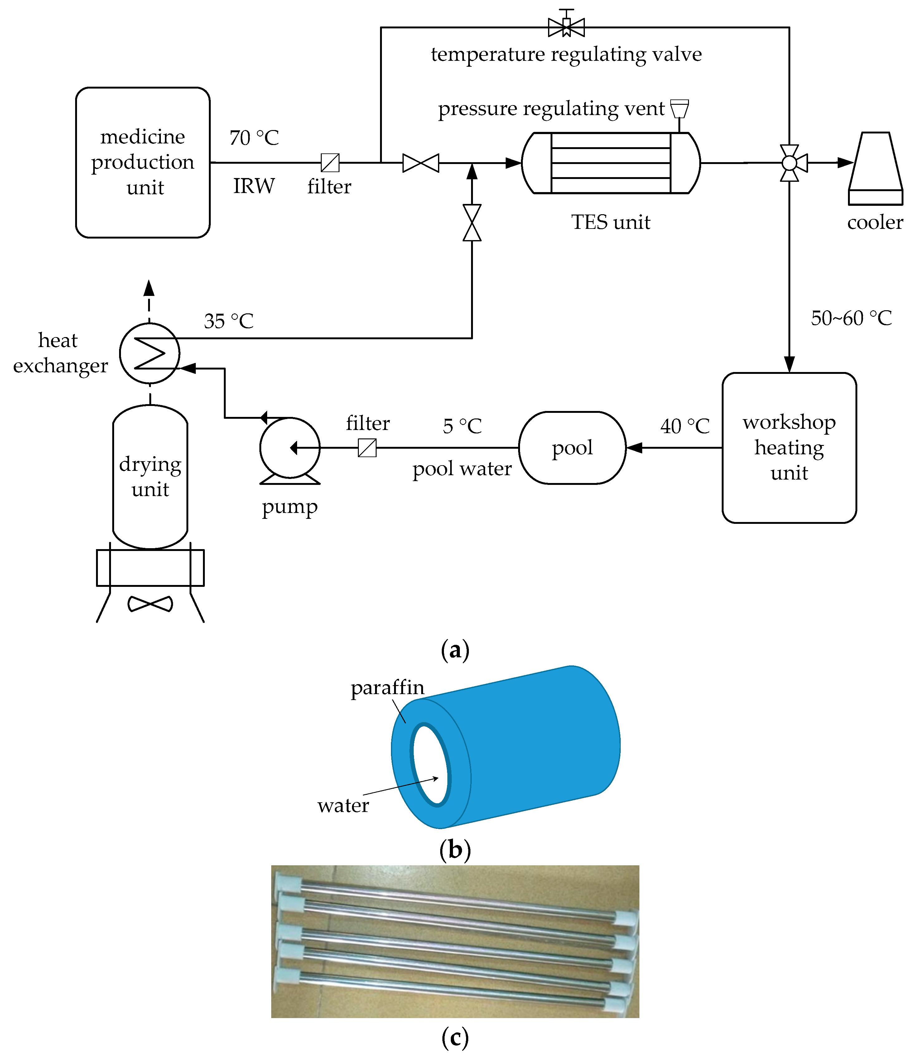
In a pharmaceutical plant, IRW is being used in the workshop heating system. Given the energy loss and pipe requirement, the temperature of IRW supplied to the workshop heating unit should be within 50 to 60 °C. Thus, the IRW, from a medicine production unit, with the original temperature of 70 °C passes through a temperature regulating valve before enters the workshop heating unit. If the production unit works at its rated load, only 20.4 h per day are needed to produce the medicine, according to the market orders. During the remaining 3.6 h, the medicine production unit stops work; thus, there is no IRW generated. In practice, to meet the requirement of continuous workshop heating, the medicine production unit operates at a relatively low load, approximately 85%, which consumes some extra energy consumption and cost.
To solve this problem, a novel workshop heating system using IRW through a TES unit is proposed, as shown in Figure 1. In the proposed system, the medicine production unit works at its rated load, in which point the energy efficiency of the production unit performs the best. Thus, the continuous low-load-operating of the medicine production unit is replaced by a batch-type rated-load-operating, leading to a corresponding intermittent of IRW generation. However, the heat requirement of the workshop heating unit is continuous. Thus, the TES unit, with paraffin wax as a PCM, plays a crucial role in the system. When the medicine production unit runs, the workshop heating unit receives filtered IRW passing through the temperature regulating valve, after which the temperature of IRW is regulated to 50 to 60 °C; meanwhile part of the IRW flows through the tube of the TES unit (see Figure 1b), and the heat of this part of the IRW with the temperature of 70 °C is stored in the paraffin wax filled in the shell of the TES unit, leading to a phase change of the paraffin wax from solid to liquid. When the medicine production unit stops, there is no IRW produced from production unit, and the TES unit is in an exothermic state. The filtered water from a pool, with the temperature of 5 °C, is pumped into a heat exchanger, in which the pool water is preheated to 35 °C by the hot wind from a drying unit next to the medicine production unit. The preheated pool water enters the tube of the TES unit to extract the heat stored in the liquid paraffin wax in the previous cycle. After exchanging heat with paraffin wax, the pool water is finally heated to 50 to 60 °C and sent to the workshop heating unit; whereas the paraffin wax changes from liquid state to the solid. The TES unit is a set of shell-and-tube pipe columns (see Figure 1c). Fluid, either IRW or pool water, flows in the tube after filtered; and paraffin wax is stored in the shell. The shell is made of carbon steel, while the tube is pure copper covered by thermal insulators. In addition, a pressure regulating vent [37] is installed necessarily to protect the structural integrity of the TES unit from excessive pressure caused by volumetric expansion of the paraffin wax.

3. Mathematical Model

3.1. Heat Storage Process

The main component of the TES unit is a set of hollow cylinders filled with paraffin wax in the shell, and IRW flows inside the tube. The shell-and-tube pipe columns are uniformly arranged, so this study only focuses on an infinitesimal unit, as shown in Figure 2. In Figure 2, x denotes the axial direction; L is the length of a single tube of the TES unit; ri, ro, and r0 are the internal radius of the tube, the external radius of the tube, and the internal radius of the shell, respectively; and rp(x,τ) is the melting radius of the paraffin wax.
Combining the methods and results reported in [32,34,40,41,42,43,44,45], some assumptions are given as follows before elaborating the mathematical model:
  • It is assumed that the paraffin wax is smooth and with constant physical properties.
  • IRW and pool water are incompressible fluid and Newtonian fluid.
  • The entrance effects of fluid flow and heat transfer are ignored.
  • The initial temperature of the paraffin wax is uniform.
  • The external wall of the shell is thermally insulated.
  • The axial heat conductions of IRW, pool water, and paraffin wax are neglected.
  • Natural convection when the phase change occurs in paraffin wax is not considered.
  • The specific volumetric dilatation of paraffin wax is regarded as 0.
It should be noted that during phase change from solid to liquid, the volume expansion is 11.76%, according to our experimental results under room temperature of 19 °C. However, it is difficult to consider the volume change in the modeling and the volume expansion is usually neglected [46,47]. Thus, this work regards the volume change as 0, which is an oversimplification, but this is presumed to provide a useful insight into the thermal behaviors of paraffin wax. In addition, in the design of the workshop heating system mentioned above, a pressure regulating vent is used to protect the TES unit from excessive pressure caused by volumetric expansion of the paraffin wax.
In the heat storage process, two heat transfer processes exist. One is the heat exchange between IRW and the interior tube, the other is the heat transfer between the interior tube and paraffin wax. Their energy balance equations can be expressed as:
c m t w ( x , τ ) x = 2 π r i h ( t w ( x , τ ) t s ( x , τ ) )
and
ρ H r p r p ( x , τ ) τ = h r i ( t w ( x , τ ) t s ( x , τ ) )
where c is the specific heat capacity of water; m is the flow rate of IRW into the TES unit; tw is the temperature of IRW; h is the convection coefficient of IRW; ts is the temperature of tube wall; ρ is the density of paraffin wax; and H is the latent heat of paraffin wax.
The thermal resistance of the interior tube, made of copper, is not counted since its thermal conductivity can be as high as 399 W/(m·K). According to the heat flux balance in the radial torus, the relationship among IRW temperature, tube temperature, paraffin wax temperature, and thermal resistances is
t s ( x , τ ) T w ( x , τ ) t m t w ( x , τ ) = R w R w + R p ( x , τ ) ,
where tm is the phase change temperature of paraffin wax; and Rp and Rw are thermal resistances of paraffin wax, and heat transfer between IRW and the tube, respectively, and are expressed as
R w = 1 / h
and
R p ( x , τ ) = r i λ ln r p ( x , τ ) r o
where λ is the thermal conductivity of solid paraffin wax.
Let
R ( x , τ ) = R f R f + R p ( x , τ )
then Equations (1) and (2) can be rewritten as
t w ( x , τ ) x = 2 h π r i c m R ( x , τ ) ( t w ( x , τ ) t m )
and
r p 2 ( x , τ ) τ = 2 h r i ρ H R ( x , τ ) ( t w ( x , τ ) t m )
Boundary condition and initial conditions are given by:
{ t w ( x = 0 , τ ) = t in , t w ( x , τ = 0 ) = t m , r p ( x , τ = 0 ) = r o ,
where tin is the IRW temperature at the inlet of TES unit.
According to Equations (6) to (8), the following equations can be obtained:
t w ( x , τ ) = t m + ( t in t m ) exp ( 2 h π r i c m R ( x , τ ) x )
and
r p ( x , τ ) = r o 2 + 0 τ 2 h r i ρ H R ( x , τ ) ( t w ( x , τ ) t m ) d τ
Based on Equations (9) and (10), the recurrence formulae of IRW temperature and the melting radius of paraffin wax during the solid-to-liquid phase change process are given by:
t w ( x , τ ) = t m + ( t w ( x Δ x , τ ) t m ) exp ( 2 h π r i c m x 1 h + r i λ ln r p ( x , τ Δ τ ) r o )
and
r p ( x , τ ) = r p 2 ( x , τ Δ τ ) + 0 τ 2 r i ρ H 1 1 h + r i λ ln r p ( x , τ Δ τ ) r o ( t w ( x , τ ) t m ) d τ
Note that if r p ( x , τ ) = r 0 it means the melting radius has reached its maximum value, after which the melting radius at location x cannot continue to expand. Label this location as X(τ), and the melting process can be divided into:
(1)
When x > X ( τ Δ τ ) , it is a heat storage in phase change process, then x in Equations (11) and (12) is replaced by ( x X ( τ Δ τ ) ) before the next recurrence.
(2)
When x X ( τ Δ τ ) , it is a heat transfer in single liquid phase, then r p ( x , τ ) = r 0 , t w ( x , τ ) = t in ( τ ) .

3.2. Heat Release Process

There are no essential differences between heat release process and the storage, except the phase change of paraffin wax. In the release process, fluid that flows through the interior tube is pool water, and the initial phase of paraffin wax is liquid.
Likewise, the recurrence formulae of the temperature of pool water and the solidification radius of paraffin wax during the liquid-to-solid phase change process are given by:
t w ( x , τ ) = t m ( t m t w ( x Δ x , τ ) ) exp ( 2 π r i c m x 1 h + r i λ ln r p ( x , τ Δ τ ) r o ) ,
and
r p ( x , τ ) = r p 2 ( x , τ Δ τ ) + 0 τ 2 r i ρ H 1 1 h + r i λ ln r p ( x , τ Δ τ ) r o ( t m t w ( x , τ ) ) d τ ,
where t w is the temperature of pool water; m is the flow rate of pool water entering the TES unit; h is the convection coefficient of the pool water; λ is the thermal conductivity of liquid paraffin wax; and r p is the solidification radius of liquid paraffin wax.
The boundary condition and initial conditions are given as follows:
{ t w ( x = 0 , τ ) = t in , t w ( x , τ = 0 ) = t m , r p ( x , τ = 0 ) = r o ,
where t in is the temperature of pool water at the inlet of TES unit.
It is also worth noting that if r p ( x , τ ) = r 0 it means the solidification radius has reached its maximum value, after which the solidification radius at location x cannot continue to expand. Label this location as X ( τ ) , and the melting process can be decomposed into:
(1)
When x > X ( τ Δ τ ) , x in Equations (13) and (14) is replaced by ( x X ( τ Δ τ ) ) before the next recurrence.
(2)
When x X ( τ Δ τ ) , r p ( x , τ ) = r 0 , t w ( x , τ ) = t in ( τ ) .

3.3. Parameters Determination

Paraffin is a mixture with no fixed melting point but a phase change temperature range. The temperature range is one of the most basic parameters determining the working environment of paraffin. In practice, the operating temperature should correspond to its phase change temperature range, otherwise the latent heat cannot be used rationally. In addition, the latent heat of paraffin wax is another crucial parameter, which directly affects the heat absorbed or extracted during the phase change process. Thus, before modeling the thermal behaviors of the TES unit, the phase change temperature range and the latent heat of the selected technical paraffin wax should be measured first.
To determine the phase change temperature range, some paraffin wax in a 100 mL beaker is immersed in a constant temperature bath. After it is melted completely, the paraffin wax is stirred well by using a glass rod. Then, a handheld digital thermometer is placed in the center of the molten paraffin wax. Then the paraffin wax is cooled at ambient temperature. The solidified paraffin wax is immersed in the temperature bath of 80 °C by adjusting the thermostats, ensuring the water surface is slightly higher than that of the paraffin wax in liquid state. The temperature is recorded every 30 s from 30 °C to the temperature at which the paraffin wax is melted completely. Figure 3 shows the relationship between paraffin wax temperature and time. It can be seen that the phase change temperature range was 47 °C to 56 °C. In the first 9 min, the temperature of paraffin wax rose fast since it stored the sensible heat as a solid. During 9 to 22 min, paraffin wax absorbed the latent heat with a relatively smaller slope. After 22 min heating, the fully melted paraffin wax stored sensible heat again with a second rapid temperature increase.
The latent heat of the paraffin wax can be obtained by performing differential scanning calorimeter (DSC). In this work, the NETZSCH STA 409 PC Luxx® thermal analyzer is used. Figure 4 depicts the DSC measuring result of heat flux. It can be found that there were two absorption peaks during the whole temperature change process. The first one means the solid-to-solid phase change, at which the crystal form changes while the heat absorbed is relatively small. The latter is the solid-to-liquid phase change with a distinct heat absorption. By using the software Proteus Analysis, the latent heat of the paraffin wax was obtained as 171.4 kJ/kg.

4. Model Validation

The physical properties of paraffin wax and water, and the dimensions of shell and tube are listed in Table 1, Table 2 and Table 3.
Before applying the mathematical model to an IRW-driven workshop heating application, it is necessary to validate that the established model is suitable for determining the thermal performance of the TES unit. A simply-equipped test device is built as shown in Figure 5, and the simulation is conducted by using MATLAB R2014a. In the validation experiment, the initial conditions and the shell and tube parameters are set the same as the simulation cases except the number of the shell-and-tube structured pipe. In the axial direction of the test device, ten thermocouples are arrayed at regular distances.
Figure 6 shows the comparison of the experimental results and simulation data of water temperatures. It is observed that the two approaches agree well, with very similar trends for the temperature of water. According to Figure 6, the maximum errors of the simulation data are 4.87% and 7.44% for heat storage and release processes, respectively. The errors are within an acceptable range. This therefore validates the mathematical model; and thus, the models can be used to simulate the thermal behaviors of the paraffin wax in the TES unit.

5. Results and Discussions

The real recurrence formulae of heat storage and release processes can be obtained by substituting parameters in Table 1, Table 2 and Table 3 into Equations (11) to (14). The detailed solving method is shown in Figure 7, with the axial step length Δ x = 0.01 m and the time step length Δ τ = 1 s. A similar solving procedure for heat release process is not re-described here.
Figure 8 presents the profile of melting radius of paraffin wax along the tube length direction at various times for heat storage process. It was indicated that the paraffin wax at IRW entrance melted quickly, with the average melting velocity of 0.50 cm/h, because of the relatively great temperature difference between IRW and paraffin wax. The melting radius decreased with the increasing distance along the tube length. At the outlet of the tube, the melting velocity of paraffin wax was the lowest, with the average value of 0.08 cm/h, corresponding to the smallest melting radius. In the first 3.03 h, paraffin wax at the IRW entrance was not entirely melted, and the distance between two melting curves presented a shape of “from bigger to smaller”. At the moment of 3.03 h, the melting radius of paraffin wax at the inlet reached its maximum value, i.e., the paraffin wax at the IRW entrance melted completely. The heat storage process after 3.03 h could be regarded as a moving-back IRW entrance, and thus the melting curves also moved back. With the increasing time, the melting radius of paraffin wax at each location increased, resulting in a gradually reduced distance between two adjacent curves. After 8-h heat transfer, the melted paraffin wax accounted for 90.8%, and the melting radius at the outlet reached 3.66 cm.
Figure 9 describes the profile of IRW temperature along the tube length direction at several times for heat storage process. At the inlet of the tube, the IRW revealed a substantial drop of temperature as a result of the marked heat exchange, for the big temperature difference between the IRW and paraffin wax. As the distance along the tube increased, the temperature difference between IRW and paraffin wax decreased. In the first 3.03 h, the paraffin wax at IRW entrance was melting, and the temperature change of IRW there varied from that at the outlet, because of the different thermal resistances corresponding to their individual melting radius. After 3.03 h, the paraffin wax at the entrance melted completely, and the melting cross-section presented a backward shift, which resulted in an expanding temperature difference and a rapid melting velocity; and thus the temperature of IRW at outlet of the tube varied appreciably with time. After 8-h heat transfer, the melting cross-section had moved to the location x = 2 m, and the IRW temperature at the outlet had reached 64 °C, when the heat storage effect appeared rather unnoticeable.
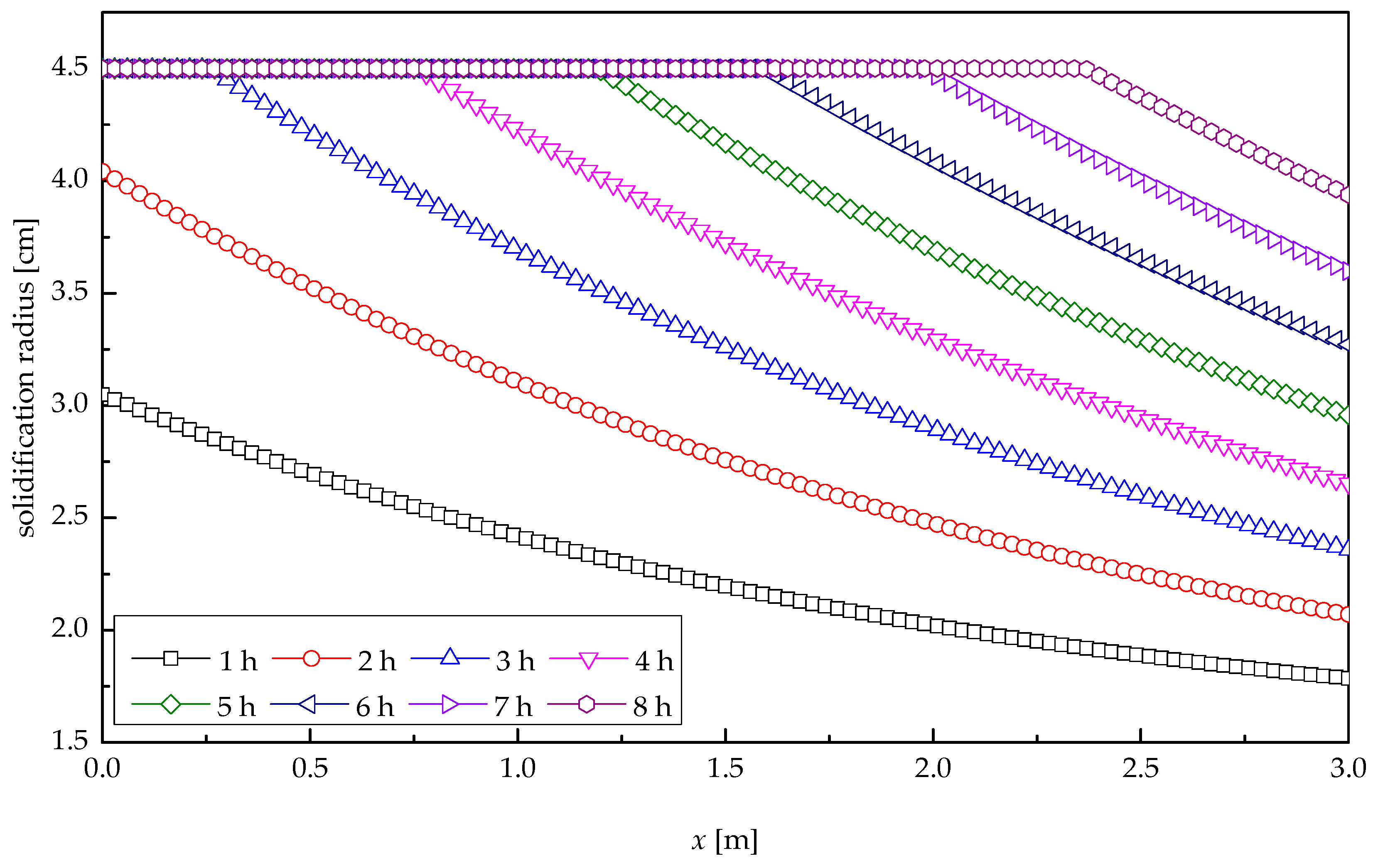
Figure 10 shows the profile of solidification radius of paraffin wax along the tube length direction at various times for heat release process. It was indicated that the paraffin wax at pool water entrance solidified quickly, with the average solidification velocity of 0.60 cm/h. The solidification radius decreased with the increasing distance along the tube length. At the outlet of the tube, the solidification velocity of paraffin wax was the lowest, with the average value of 0.12 cm/h, corresponding to the smallest solidification radius. In the first 2.48 h, paraffin wax at the pool water entrance was not entirely solidified. At the moment of 2.48 h, the solidification radius of paraffin wax at the inlet reached its maximum value, i.e., the paraffin wax at the pool water entrance solidified completely, after which the solidification cross-section showed a moving-back shift. After 8-h heat transfer, the solidified paraffin wax accounted for 98.1%, and the solidification radius at the outlet reached 3.94 cm.
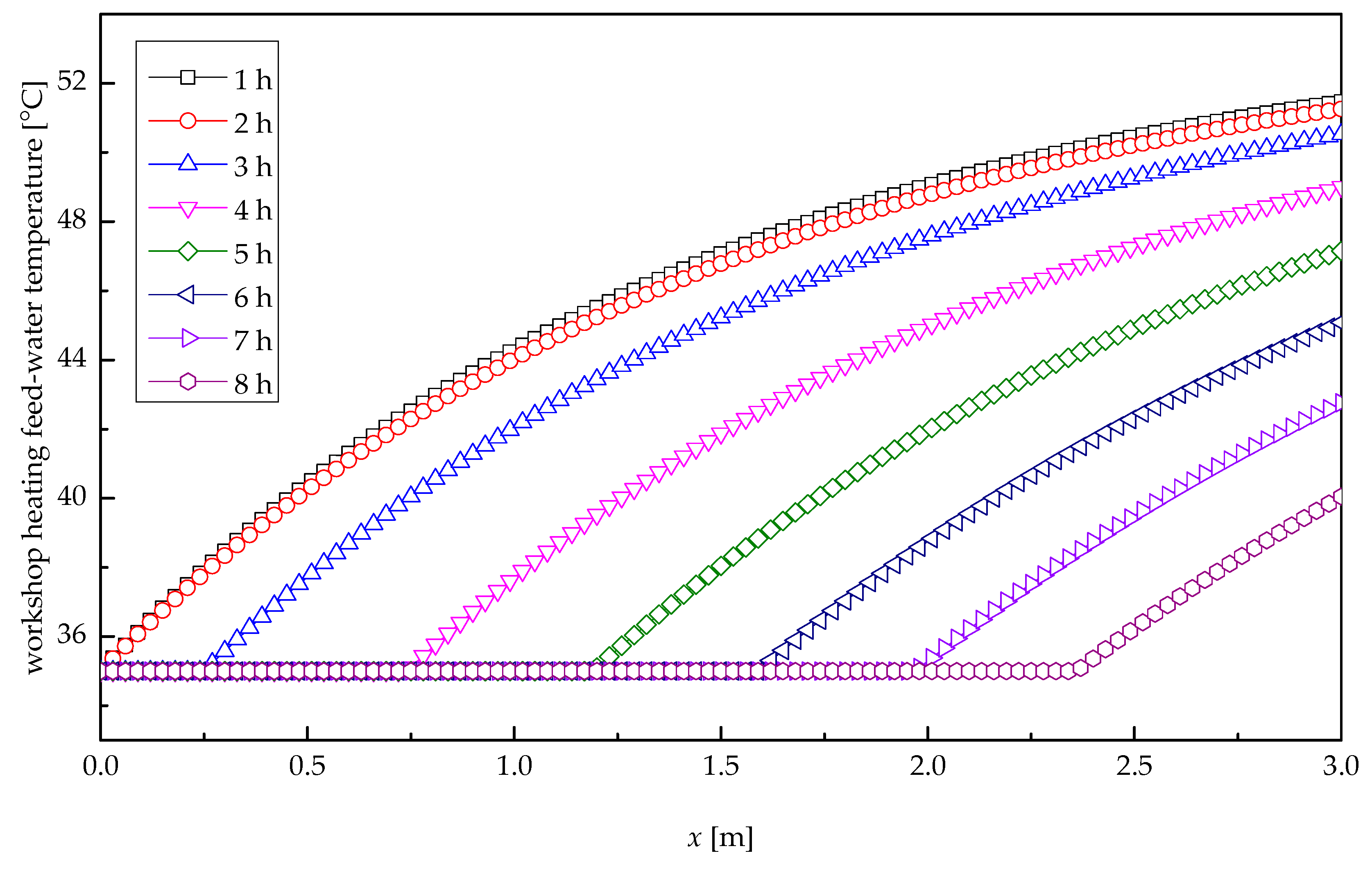
Figure 11 depicts the profile of the temperature of workshop heating feed-water along the tube length direction at several times for heat release process. At the inlet of the tube, the pool water presented a substantial rise of temperature as a result of the marked heat exchange, due to the big temperature difference between pool water and paraffin wax. With the increasing distance along the tube length, the temperature difference between pool water and paraffin wax decreased, resulting in a slow increase in the temperature of workshop heating feed-water. In the first 2.48 h, the outlet temperatures of pool water remained stable, and the temperature change of pool water there differed from that at the outlet, because their thermal resistances related to their solidification radii were greatly different. After 2.48 h, the paraffin wax at the entrance solidified completely, and the solidification cross-section presented a backward shift, which resulted in an expanding temperature difference and a rapid solidification velocity; thus, the temperature of pool water at the outlet of the tube varied appreciably with time. After 8-h heat transfer, the pool water temperature at the outlet was only 40 °C. It is after about 3.32-h heat exchange that the temperature of workshop heating feed-water reduced to 50 °C, i.e., the minimum required temperature of the heating system. Therefore, the meaningful heat release time was 3.32 h.
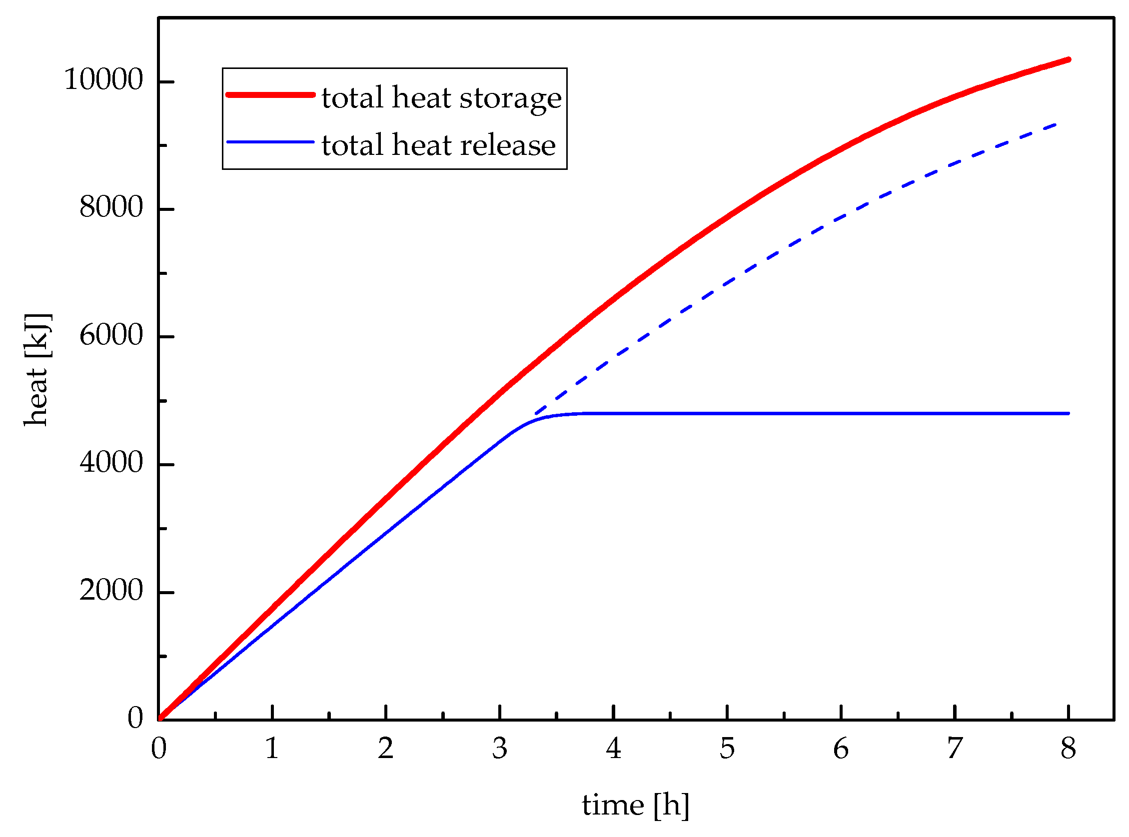
Figure 12 illustrates the total heat storage and total heat release varying with time. The total heat storage would continue increasing until the paraffin wax melted entirely; while the total heat release would continue decreasing until the last paraffin wax solidified. However, the change rates of heat storage and release were gradually becoming slow. During the meaningful heat release period, the total heat release was 4805 kJ. After the first 3.32 h, the temperature of workshop heating feed-water was less than 50 °C which did not satisfy the requirement of workshop heating unit.
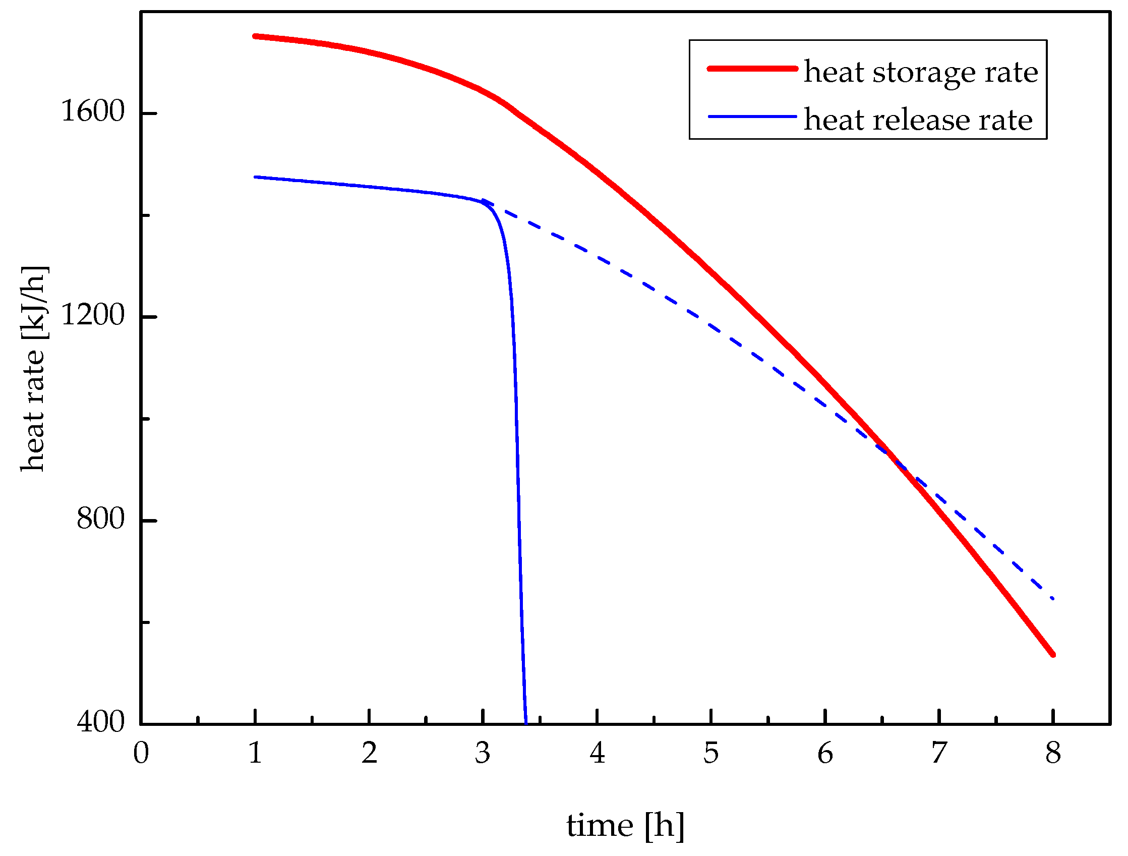
Heat storage rate of this system is defined as the amount of heat stored in the paraffin wax per unit time, and heat release rate is the amount of heat released from the paraffin wax per unit time. The changes of heat storage rate and release rate with time are shown in Figure 13. It can be seen that both heat storage rate and heat release rate decreased with the increasing time, which is because the temperature difference between paraffin wax and heat exchange fluid was bigger in the first period and smaller in the rest. It again confirmed the change of thermal resistance in paraffin wax caused by the changing melting radius and solidification radius of paraffin wax as shown in Figure 9 and Figure 11.
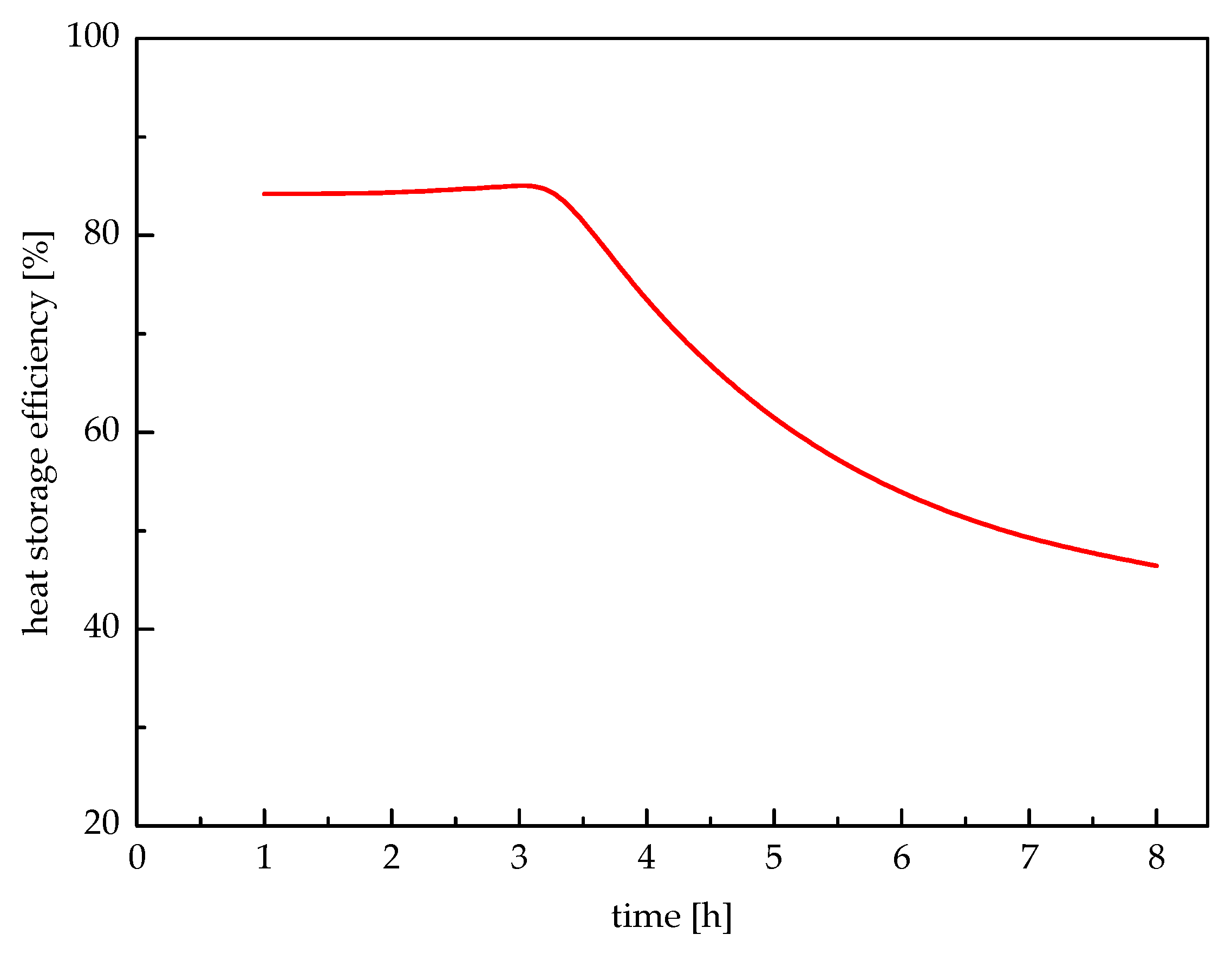
Storage efficiency of the system is defined as the ratio of the heat extracted to the heat stored in the paraffin wax. The storage efficiency of the system is illustrated in Figure 14. It can be seen that in the first stage, the storage efficiency maintained at a higher level of appropriate 85% and had a very small increase with the increasing time. However, after the first 3.32 h, the storage efficiency decreased as the heat storage time increased. This is because that the meaningful heat extraction time was only 3.32 h. It is indicated that the storage efficiency of the proposed system was 43.78% for a storage cycle of 20.68-h storage and 3.32-h release.
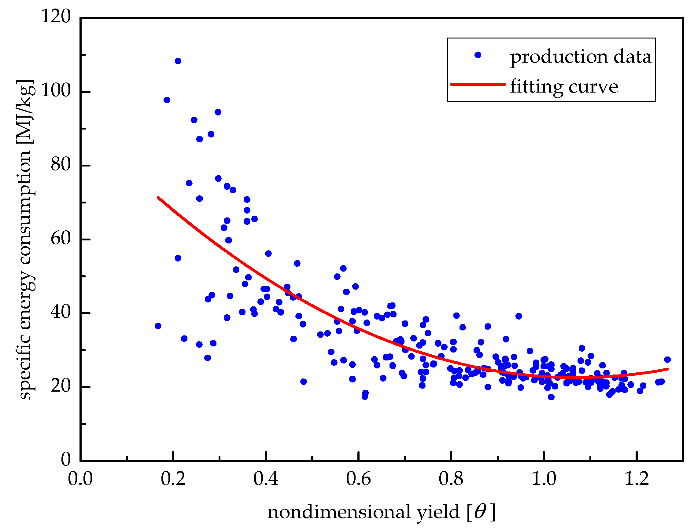
Figure 15 shows the relationship between the specific energy consumption of the medicine production unit and the corresponding yield. According to the production data from January to August of 2016, the fitting formula is given as:
b = 59.78 θ 2 128.02 θ + 91.13
where b is the specific energy consumption, and θ is the non-dimensional yield expressed as:
θ = P / P r ,
where P and Pr are the real yield and rated yield of the medicine production unit, respectively.
As reported in Section 2, the low-load-operated continuous medicine production unit works under the load rate of appropriate 85%, while the proposed system is batch-type rated-load-operated. From Equation (16), the energy saving rate of the proposed system is
ϕ = b ( θ = 0.85 ) b ( θ = 1 ) b ( θ = 0.85 ) × 100 % = 10.25 %
Though some of the results are qualitatively easy to understand, it is still scientifically significant to obtain the quantitative changing trends. The main contribution of this paper is to quantitatively determine the fluid temperature, the melting/solidification radius of paraffin wax along the tube, the total heat stored and released, the heat storage/release rate, the storage efficiency during the meaningful period, and the energy saving rate of the investigated application.
It should be noted that there are several types of heating system for industrial workshops. These heating systems in workshops can affect the thermal performance of TES unit. Thus, there are also limitations of this proposed workshop heating system for the design parameters. For instance, the pool water of 5 °C can be used to extract heat from the TES unit only if it can be preheated to 35 °C before entering the TES unit. However, in some medicine production processes, the heat used to preheat pool water is not available. Moreover, the flow rates of IRW and hot wind should match the heat requirements of the workshop heating unit and drying unit, respectively.

6. Conclusions

To use the IRW in a pharmaceutical plant, a workshop heating system using IRW through a TES unit with paraffin wax as a PCM is designed. In the proposed system, the medicine production unit works at its rated load, rather than the present low-load-operating of appropriate 85%. In the TES unit, paraffin wax is filled in the shell; IRW and pool water flows in the interior tube.
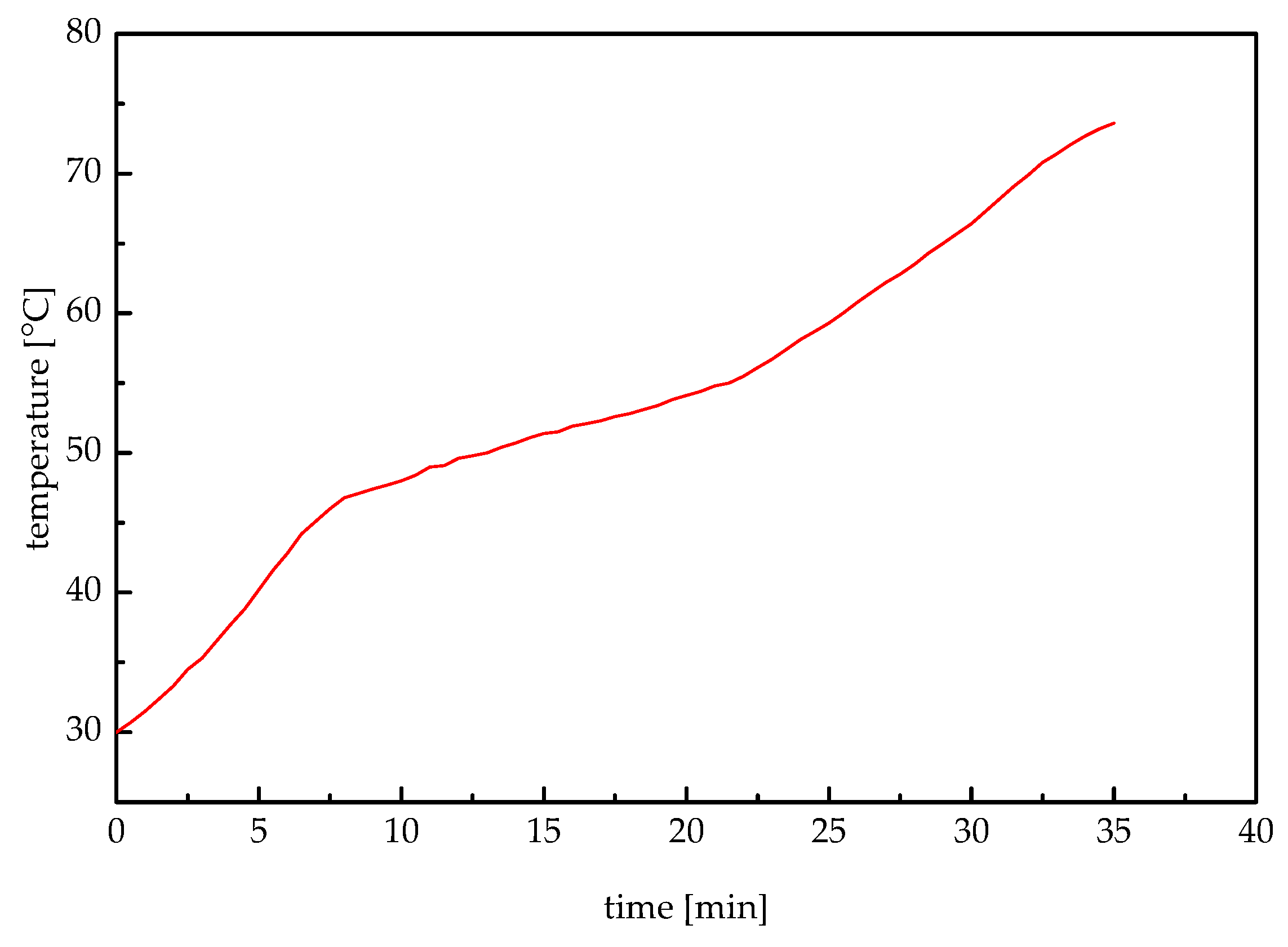
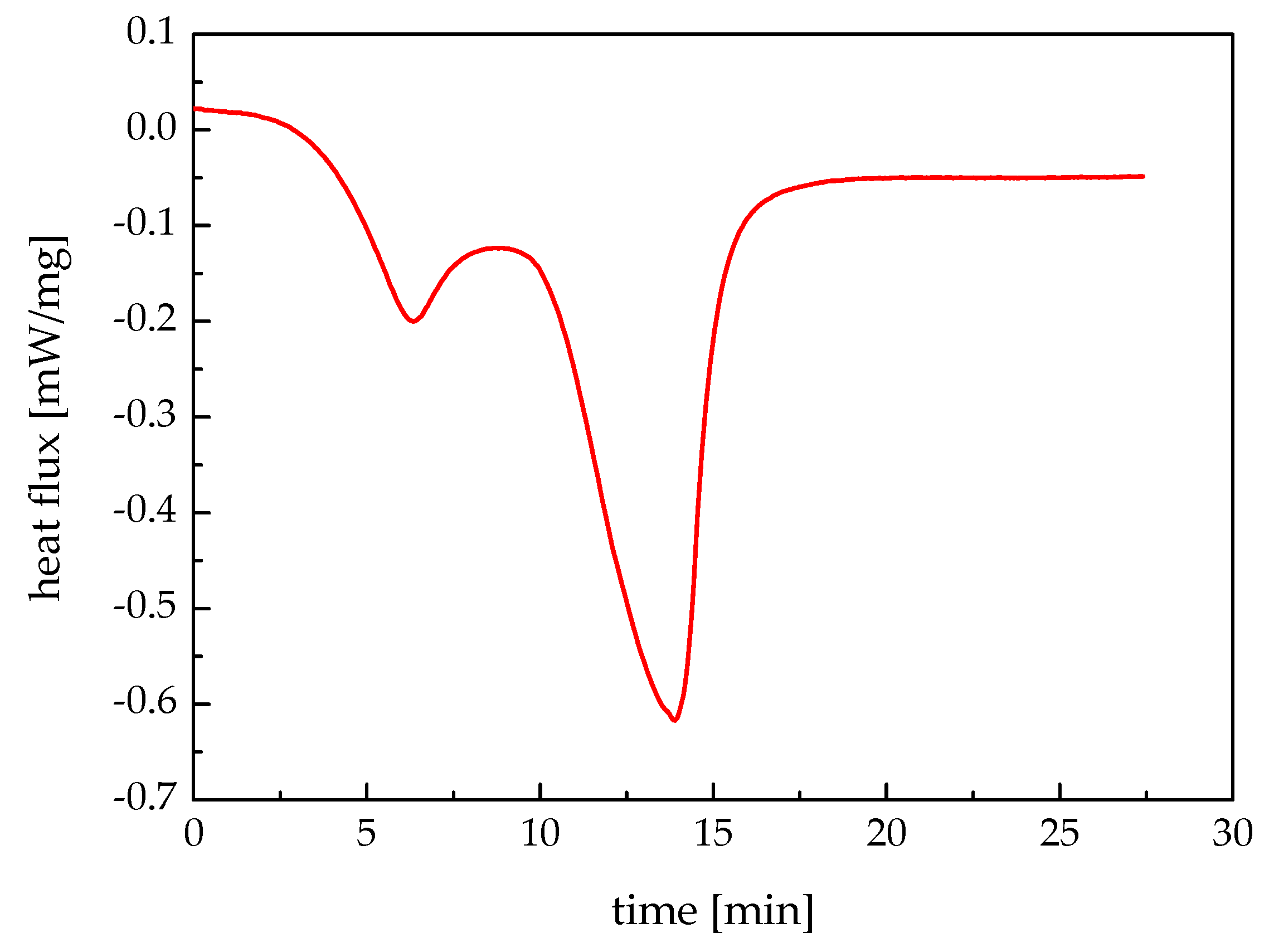
The mathematical models of heat storage and heat release processes are established, and the iterative formulae of the fluid temperature, the melting radius, and the solidification radius are obtained. In addition, the melting temperature range and the latent heat are measured by performing DSC. The melting temperature range of the investigated paraffin wax was 47 °C to 56 °C, and its latent heat was 171.4 kJ/kg.
The relationships between some quantities, such as melting radius, solidification radius, IRW temperature and workshop heating feed-water temperature, the pipe length, and time in the storage and release processes are simulated. It is concluded that the meaningful heat release time was 3.32 h in the investigated application. In addition, total heat storage and total heat release increased with the increasing time. During the meaningful heat release period, the total heat release was 4805 kJ. However, both heat storage rate and heat release rate decreased with the increasing time. The storage efficiency of this system maintained at a higher level of appropriate 85% at the first 3.32 h and decreased quickly as the heat storage time increased. For the system designed in this work, the entire storage efficiency was 43.78%. Additionally, the medicine production unit in this system had an energy saving rate of 10.25% compared with before.

Acknowledgments

This work was supported by the Fundamental Research Funds for the Central Universities, China, and the National Natural Science Foundation of China (21561122001 and 71403175).

Author Contributions

Wenqiang Sun designed the overall research; Zuquan Zhao developed the mathematical models and conducted the modeling, Yanhui Wang analyzed the data; and Wenqiang Sun wrote the paper.

Conflicts of Interest

The authors declare no conflict of interest.

Nomenclature

Variables

bspecific energy consumption of medicine production unit [MJ/kg]
cspecific heat capacity of water [kJ/(kg·K)]
hconvection coefficient of IRW [W/(m2·K)]
h convection coefficient of pool water [W/(m2·K)]
Hlatent heat of paraffin wax [kJ/kg]
Llength of a tube in TES unit [m]
mflow rate of IRW into TES unit [kg/s]
m flow rate of pool water into TES unit [kg/s]
Preal yield of medicine production unit [kg/h]
Prrated yield of medicine production unit [kg/h]
riinternal radius of tube [m]
roexternal radius of tube [m]
rpmelting radius of solid paraffin wax [m]
r p solidification radius of liquid paraffin wax [m]
r0internal radius of shell [m]
Rpthermal resistance of paraffin wax [m2·K/W]
Rwthermal resistance of IRW-tube heat transfer [m2·K/W]
tinIRW temperature at TES unit inlet [°C]
t in pool water temperature at TES unit inlet [°C]
tmphase change temperature [°C]
tstemperature of tube wall [°C]
twtemperature of IRW [°C]
t w temperature of pool water [°C]
xaxial direction
Xlocation at the maximum melting radius
X location at the maximum solidification radius

Greek Symbols

θnondimensional yield of medicine production unit [–]
λthermal conductivity of solid paraffin wax [W/(m·K)]
λ thermal conductivity of liquid paraffin wax [W/(m·K)]
ρparaffin wax density [kg/m3]
τtime [s, h]
φenergy saving rate [%]

Abbreviations

DSCdifferential scanning calorimeter
IRWindustrial residual water
PCMphase change material
TESthermal energy storage

References

  1. Erdem, H.H.; Dagdas, A.; Sevilgen, S.H.; Cetin, B.; Akkaya, A.V.; Sahin, B.; Teke, I.; Gungor, C.; Atas, S. Thermodynamic analysis of an existing coal-fired power plant for district heating/cooling application. Appl. Therm. Eng. 2010, 30, 181–187. [Google Scholar] [CrossRef]
  2. Arteconi, A.; Patteeuw, D.; Bruninx, K.; Delarue, E.; D’haeseleer, W.; Helsen, L. Active demand response with electric heating systems: Impact of market penetration. Appl. Energy 2016, 177, 636–648. [Google Scholar] [CrossRef]
  3. Joubert, E.C.; Hess, S.; van Niekerk, J.L. Large-scale solar water heating in South Africa: Status, barriers and recommendations. Renew. Energy 2016, 97, 809–822. [Google Scholar] [CrossRef]
  4. Ma, H.; Li, C.; Lu, W.; Zhang, Z.; Yu, S.; Du, N. Experimental study of a multi-energy complementary heating system based on a solar-groundwater heat pump unit. Appl. Therm. Eng. 2016, 109, 718–726. [Google Scholar] [CrossRef]
  5. Li, Y.; Xia, J.; Fang, H.; Su, Y.; Jiang, Y. Case study on industrial surplus heat of steel plants for district heating in Northern China. Energy 2016, 102, 397–405. [Google Scholar] [CrossRef]
  6. Togawa, T.; Fujita, T.; Dong, L.; Fujii, M.; Ooba, M. Feasibility assessment of the use of power plant-sourced waste heat for plant factory heating considering spatial configuration. J. Clean. Prod. 2014, 81, 60–69. [Google Scholar] [CrossRef]
  7. Eriksson, L.; Morandin, M.; Harvey, S. Targeting capital cost of excess heat collection systems in complex industrial sites for district heating applications. Energy 2015, 91, 465–478. [Google Scholar] [CrossRef]
  8. Sun, W.; Zhang, F. Design and thermodynamic analysis of a flash power system driven by process heat of continuous casting grade steel billet. Energy 2016, 116, 94–101. [Google Scholar] [CrossRef]
  9. Hosseini, S.R.; Amidpour, M.; Behbahaninia, A. Thermoeconomic analysis with reliability consideration of a combined power and multi stage flash desalination plant. Desalination 2011, 278, 424–433. [Google Scholar] [CrossRef]
  10. Chang, C.; Wang, Y.; Feng, X. Indirect heat integration across plants using hot water circles. Chin. J. Chem. Eng. 2015, 23, 992–997. [Google Scholar] [CrossRef]
  11. De Oliveira, R.G.; Generoso, D.J. Influence of the operational conditions on the performance of a chemisorption chiller driven by hot water between 65 °C and 80 °C. Appl. Energy 2016, 162, 257–265. [Google Scholar] [CrossRef]
  12. Sun, W.; Yue, X.; Wang, Y. Exergy efficiency analysis of ORC (Organic Rankine Cycle) and ORC-based combined cycles driven by low-temperature waste heat. Energy Convers. Manag. 2017, 135, 63–73. [Google Scholar] [CrossRef]
  13. Kim, D.K.; Lee, J.S.; Kim, J.; Kim, M.S.; Kim, M.S. Parametric study and performance evaluation of an organic Rankine cycle (ORC) system using low-grade heat at temperatures below 80 °C. Appl. Energy 2017, 189, 55–65. [Google Scholar] [CrossRef]
  14. Ergun, A.; Ozkaymak, M.; Koc, G.A.; Ozkan, S.; Kaya, D. Exergoeconomic analysis of a geothermal organic Rankine cycle power plant using the SPECO method. Environ. Prog. Sustain. Energy 2017, in press. [Google Scholar] [CrossRef]
  15. Sun, W.; Hong, Y.; Wang, Y. Operation optimization of steam accumulators as a thermal energy storage and buffer unit. Energies 2017, 10, 17. [Google Scholar] [CrossRef]
  16. Cheng, W.; Xie, B.; Zhang, R.; Xu, Z.; Xia, Y. Effect of thermal conductivities of shape stabilized PCM on under-floor heating system. Appl. Energy 2015, 144, 10–18. [Google Scholar] [CrossRef]
  17. Xia, Y.; Zhang, X.S. Experimental research on a double-layer radiant floor system with phase change material under heating mode. Appl. Therm. Eng. 2016, 96, 600–606. [Google Scholar] [CrossRef]
  18. Zhou, G.; He, J. Thermal performance of a radiant floor heating system with different heat storage materials and heating pipes. Appl. Energy 2015, 138, 648–660. [Google Scholar] [CrossRef]
  19. Furbo, S. Using water for heat storage in thermal energy storage (TES) systems. In Advances in Thermal Energy Storage Systems: Methods and Applications; Cabeza, L.F., Ed.; Woodhead Publishing: Cambridge, UK, 2015; pp. 31–47. [Google Scholar]
  20. Okello, D.; Foong, C.W.; Nydal, O.J.; Banda, E.J.K. An experimental investigation on the combined use of phase change material and rock particles for high temperature (~350 °C) heat storage. Energy Convers. Manag. 2014, 79, 1–8. [Google Scholar] [CrossRef]
  21. Guo, P.; Wang, Y.; Li, J.; Wang, Y. Thermodynamic analysis of a solar chimney power plant system with soil heat storage. Appl. Therm. Eng. 2016, 100, 1076–1084. [Google Scholar] [CrossRef]
  22. Ushak, S.; Fernández, A.G.; Grageda, M. Using molten salts and other liquid sensible storage media in thermal energy storage (TES) systems. In Advances in Thermal Energy Storage Systems: Methods and Applications; Cabeza, L.F., Ed.; Woodhead Publishing: Cambridge, UK, 2015; pp. 49–63. [Google Scholar]
  23. Zhao, C.Y.; Ji, Y.; Xu, Z. Investigation of the Ca(NO3)2–NaNO3 mixture for latent heat storage. Sol. Energy Mater. Sol. Cells 2015, 140, 281–288. [Google Scholar] [CrossRef]
  24. Sun, J.Q.; Zhang, R.Y.; Liu, Z.P.; Lu, G.H. Thermal reliability test of Al–34%Mg–6%Zn alloy as latent heat storage material and corrosion of metal with respect to thermal cycling. Energy Convers. Manage. 2007, 48, 619–624. [Google Scholar] [CrossRef]
  25. Li, X.; Zhou, Y.; Nian, H.; Ren, X.; Dong, O.; Hai, C.; Shen, Y.; Zeng, J. Phase change behavior of latent heat storage media based on calcium chloride hexahydrate composites containing strontium chloride hexahydrate and oxidation expandable graphite. Appl. Therm. Eng. 2016, 102, 38–44. [Google Scholar] [CrossRef]
  26. Ouchi, Y.; Someya, S.; Munakata, T.; Ito, H. Visualization of the phase change behavior of sodium acetate trihydrate for latent heat storage. Appl. Therm. Eng. 2015, 91, 547–555. [Google Scholar] [CrossRef]
  27. Aydin, A.A.; Okutan, H. High-chain fatty acid esters of myristoyl alcohol with even carbon number: Novel organic phase change materials for thermal energy storage—1. Sol. Energy Mater. Sol. Cells 2011, 95, 2752–2762. [Google Scholar] [CrossRef]
  28. Li, C.; Fu, L.; Ouyang, J.; Tang, A.; Yang, H. Kaolinite stabilized paraffin composite phase change materials for thermal energy storage. Appl. Clay Sci. 2015, 115, 212–220. [Google Scholar] [CrossRef]
  29. Kerskes, H.; Mette, B.; Bertsch, F.; Asenbeck, S.; Drück, H. Chemical energy storage using reversible solid/gas-reactions (CWS)—Results of the research project. Energy Proc. 2012, 30, 294–304. [Google Scholar] [CrossRef]
  30. Lefebvre, D.; Tezel, F.H. A review of energy storage technologies with a focus on adsorption thermal energy storage processes for heating applications. Renew. Sustain. Energy Rev. 2017, 67, 116–125. [Google Scholar] [CrossRef]
  31. Lim, K.; Che, J.; Lee, J. Experimental study on adsorption characteristics of a water and silica-gel based thermal energy storage (TES) system. Appl. Therm. Eng. 2017, 110, 80–88. [Google Scholar] [CrossRef]
  32. Sobolčiak, P.; Abdelrazeq, H.; Gözde Özerkan, N.; Ouederni, M.; Nógellová, Z.; AlMaadeed, M.A.; Karkri, M.; Krupa, I. Heat transfer performance of paraffin wax based phase change materials applicable in building industry. Appl. Therm. Eng. 2016, 107, 1313–1323. [Google Scholar] [CrossRef]
  33. Moreno, P.; Solé, C.; Castell, A.; Cabeza, L.F. The use of phase change materials in domestic heat pump and air-conditioning systems for short term storage: A review. Renew. Sustain. Energy Rev. 2014, 39, 1–13. [Google Scholar] [CrossRef]
  34. Aadmi, M.; Karkri, M.; El Hammouti, M. Heat transfer characteristics of thermal energy storage for PCM (phase change material) melting in horizontal tube: Numerical and experimental investigations. Energy 2015, 85, 339–352. [Google Scholar] [CrossRef]
  35. Trp, A. An experimental and numerical investigation of heat transfer during technical grade paraffin melting and solidification in a shell-and-tube latent thermal energy storage unit. Sol. Energy 2005, 79, 648–660. [Google Scholar] [CrossRef]
  36. He, B.; Martin, V.; Setterwall, F. Phase transition temperature ranges and storage density of paraffin wax phase change materials. Energy 2004, 29, 1785–1804. [Google Scholar] [CrossRef]
  37. Eftekhar, J.; Haji-Sheikh, A.; Lou, D.Y.S. Hear transfer enhancement in a paraffin wax thermal storage system. J. Sol. Energy Eng. 1984, 106, 299–306. [Google Scholar] [CrossRef]
  38. Himran, S.; Suwono, A.; Mansoori, G.A. Characterization of alkanes and paraffin waxes for application as phase change energy storage medium. Energy Sources 1994, 16, 117–128. [Google Scholar] [CrossRef]
  39. Zhou, D.; Zhao, C.Y.; Tian, Y. Review on thermal energy storage with phase change materials (PCMs) in building applications. Appl. Energy 2012, 92, 593–605. [Google Scholar] [CrossRef] [Green Version]
  40. Zhang, Y.; Faghri, A. Analysis of thermal energy storage system with conjugate turbulent forced convection. J. Thermophys. Heat Transf. 1995, 9, 722–726. [Google Scholar] [CrossRef]
  41. Liu, M.J.; Fan, L.W.; Zhu, Z.Q.; Feng, B.; Zhang, H.C.; Zeng, Y. A volume-shrinkage-based method for quantifying the inward solidification heat transfer of a phase change material filled in spherical capsules. Appl. Therm. Eng. 2016, 108, 1200–1205. [Google Scholar] [CrossRef]
  42. Wang, C.; Lin, T.; Li, N.; Zheng, H. Heat transfer enhancement of phase change composite material: Copper foam/paraffin. Renew. Energy 2016, 96, 960–965. [Google Scholar] [CrossRef]
  43. Song, S.H.; Liao, Q.; Shen, W.D. Laminar heat transfer and friction characteristics of microencapsulated phase change material slurry in a circular tube with twisted tape inserts. Appl. Therm. Eng. 2013, 50, 791–798. [Google Scholar] [CrossRef]
  44. Ma, Z.W.; Zhang, P. Modeling the heat transfer characteristics of flow melting of phase change material slurries in the circular tubes. Int. J. Heat Mass Transf. 2013, 64, 874–881. [Google Scholar] [CrossRef]
  45. Sun, D.; Wang, L. Research on heat transfer performance of passive solar collector-storage wall system with phase change materials. Energy Build. 2016, 119, 183–188. [Google Scholar] [CrossRef]
  46. Shaikh, S.; Lafdi, K. Effect of multiple phase change materials (PCMs) slab configurations on thermal energy storage. Energy Convers. Manag. 2006, 47, 2103–2117. [Google Scholar] [CrossRef]
  47. Regin, A.F.; Solanki, S.C.; Saini, J.S. Latent heat thermal energy storage using cylindrical capsule: Numerical and experimental investigations. Renew. Energy 2006, 31, 2025–2041. [Google Scholar] [CrossRef]
Figure 1. The proposed workshop heating system: (a) System configuration; (b) Schematic diagram of the shell-and-tube structure of the TES unit; and (c) sets of shell-and-tube pipe columns.
Energies 10 00219 g001
Figure 2. Schematic diagram of the phase change process: (a) axial direction; and (b) radial direction.
Energies 10 00219 g002
Figure 3. Melting temperature curve.
Energies 10 00219 g003
Figure 4. Differential scanning calorimeter (DSC) measuring result.
Energies 10 00219 g004
Figure 5. Schematic diagram of the test device.
Energies 10 00219 g005
Figure 6. Comparison between simulation data and experimental results: (a) heat storage process; and (b) heat release process.
Energies 10 00219 g006
Figure 7. Computer calculation flow.
Energies 10 00219 g007
Figure 8. Melting radius profile of paraffin wax.
Energies 10 00219 g008
Figure 9. Temperature profile of the IRW.
Energies 10 00219 g009
Figure 10. Solidification radius profile of paraffin wax.
Energies 10 00219 g010
Figure 11. Temperature profile of workshop heating feed-water.
Energies 10 00219 g011
Figure 12. Total heat storage and total heat release.
Energies 10 00219 g012
Figure 13. Heat storage and release rates.
Energies 10 00219 g013
Figure 14. Change of heat storage efficiency with time.
Energies 10 00219 g014
Figure 15. Relationship between specific energy consumption and non-dimensional yield.
Energies 10 00219 g015
Table 1. Physical properties of paraffin wax.
ItemSymbolValueUnit
phase change temperaturetm47–56°C
latent heatH171.4kJ/kg
densityρ900kg/m3
thermal conductivity (solid phase)λ0.3W/(m·K)
thermal conductivity (liquid phase)λ’0.1W/(m·K)
Table 2. Physical properties of water.
ItemSymbolValueUnit
flow ratem0.278kg/s
specific heat capacityc4.18kJ/(kg·K)
convection coefficienth498W/(m2·K)
IRW temperature at the inlet of TES unittin70°C
pool water temperature at the inlet of TES unitt’in35°C
Table 3. Dimensions of shell and tube.
ItemSymbolValueUnit
tube lengthL3000mm
internal radius of the interior tuberi26mm
external radius of the interior tubero30mm
internal radius of the exterior shellr045mm

