Article

Application of Liquid Hydrogen with SMES for Efficient Use of Renewable Energy in the Energy Internet

1
School of Electrical Engineering, Wuhan University, Wuhan 430072, China
2
State Grid Hubei Electric Power Economic and Technology Research Institute, Wuhan 430077, China
*
Author to whom correspondence should be addressed.
Energies 2017, 10(2), 185; https://doi.org/10.3390/en10020185
Submission received: 6 January 2017 / Revised: 1 February 2017 / Accepted: 2 February 2017 / Published: 8 February 2017
(This article belongs to the Special Issue Advanced Energy Storage Technologies and Their Applications (AESA))

Abstract

:
Considering that generally frequency instability problems occur due to abrupt variations in load demand growth and power variations generated by different renewable energy sources (RESs), the application of superconducting magnetic energy storage (SMES) may become crucial due to its rapid response features. In this paper, liquid hydrogen with SMES (LIQHYSMES) is proposed to play a role in the future energy internet in terms of its combination of the SMES and the liquid hydrogen storage unit, which can help to overcome the capacity limit and high investment cost disadvantages of SMES. The generalized predictive control (GPC) algorithm is presented to be appreciatively used to eliminate the frequency deviations of the isolated micro energy grid including the LIQHYSMES and RESs. A benchmark micro energy grid with distributed generators (DGs), electrical vehicle (EV) stations, smart loads and a LIQHYSMES unit is modeled in the Matlab/Simulink environment. The simulation results show that the proposed GPC strategy can reschedule the active power output of each component to maintain the stability of the grid. In addition, in order to improve the performance of the SMES, a detailed optimization design of the superconducting coil is conducted, and the optimized SMES unit can offer better technical advantages in damping the frequency fluctuations.

1. Introduction

The increasing number of renewable energy sources (RESs) and distributed generators (DGs) has become a serious challenge for the stability and reliability of the electric power system, because of the fluctuation of power supply needed to meet the demand [1,2]. With the concerns related to this and other problems, e.g., conventional energy cost, greenhouse gas emissions, security of traditional power systems [3], the concept of the energy internet is proposed [4], which is composed of numerous micro-energy grids and supports the flexible access of various RESs [5]. Therefore, energy storage technology is crucial for the energy internet to suppress power fluctuations and achieve the efficient operation of RESs by decoupling the electricity generation from demand [6,7].
Superconducting magnetic energy storage (SMES) units offer quick responses to power fluctuations and the ability to deliver large amounts of power instantaneously, while their limited storage capacity is a weak point for long term operation [8]. Liquid hydrogen (LH2) storage units have the characteristics of large storage capacity [9] and economic efficiency that can make up for the disadvantages of SMES, but their response is too slow to be used as the single storage mode to support the RESs in the energy internet.
Some studies have focused on the use of LH2 as the cooling medium for SMES [10,11,12] for a long period, and the concept of liquid hydrogen with SMES (LIQHYSMES) that combines the SMES with LH2 storage units is proposed for further study [13]. The simulation and analysis of the buffering behavior of the LIQHYSMES plant model was carried out in [14] and it seems to be capable of handling even very strong variations of the imbalance between supply and demand. Also, different SMES structure designs for the 10 GJ range are compared in terms of size and ramping losses in [15], and the cost targets for different power levels and supply periods are addressed. It can be concluded from these publications that the application of LIQHYSMES are quite feasible and suitable for the energy internet.
The load frequency control (LFC) has been widely used in conventional electric power systems, and the micro-grid can maintain the stability of frequency by the optimal control, proportional integral (PI) control and other methods [16,17,18]. In the micro energy grid including LIQHYSMES units proposed here, the changes of the state of the system are fairly rapid so a controller with robust performance over a wide range of operating conditions is strongly needed for LFC in an isolated micro energy grid. The LFC of the micro-grid including the SMES was studied in [19], however the impacts of the parameters were not taken into account. The GPC algorithm can also be used to control isolated micro-grids with electric vehicles [20].
In this paper, a LIQHYSMES unit to be used as the energy storage system with RESs in the energy internet to solve the frequency instability problem is proposed. Based on the presentation of the LIQHYSMES characteristics, the benefits and applications to the energy internet are analyzed. Then a new coordinated LFC controller based on the GPC algorithm is proposed for the equivalent model of the micro energy grid with LIQHYSMES. Meanwhile, the optimization design of the superconducting coil parameters, including initial current, inductance and initial energy storage capacity is carried out in this paper.
The rest of this paper is organized as follows: Section 2 introduces the structure of the LIQHYSMES. In Section 3, the equivalent models of the components in the micro energy grid for LFC are constructed. Then, the coordinated LFC controller based on GPC is proposed in Section 4. In Section 5, the superconducting coil is optimized; the effectiveness and robustness of the proposed coordinated controller is demonstrated by numerical simulations on an isolated micro energy grid with LIQHYSMES in Section 6. Finally, conclusions are drawn in Section 7.

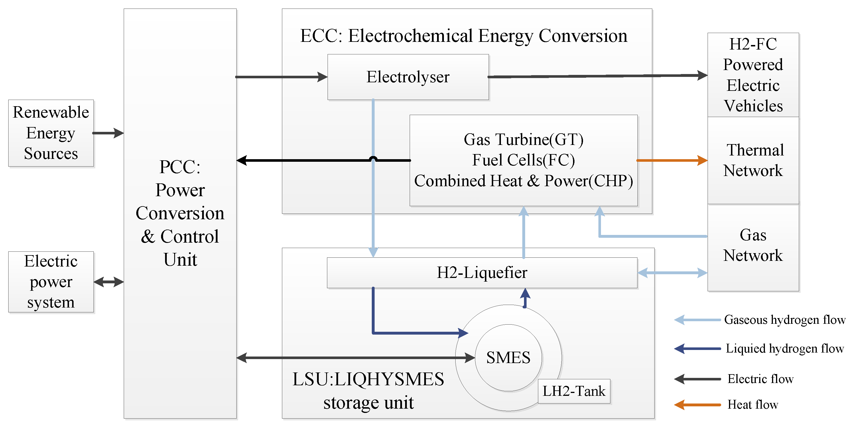
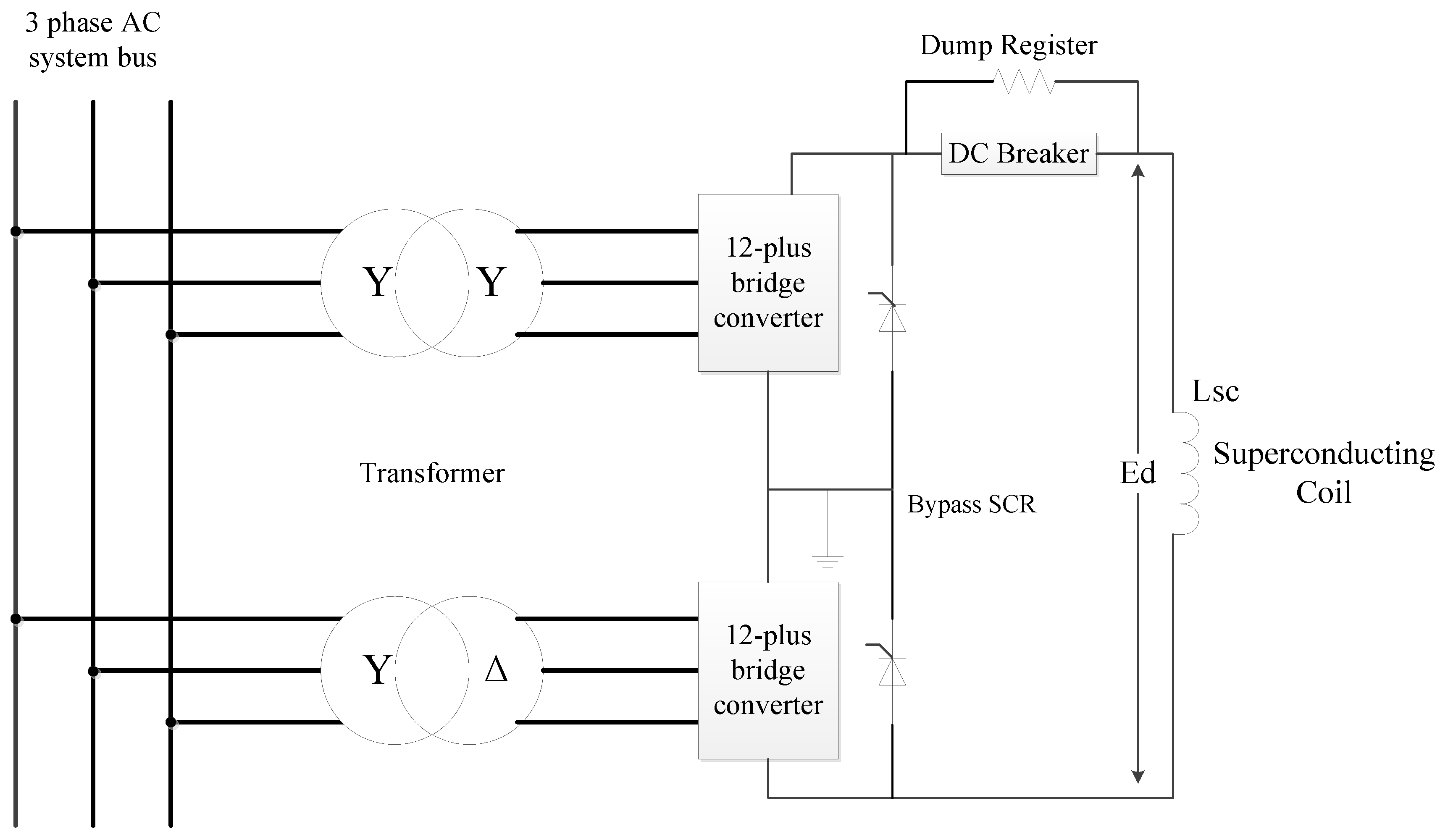
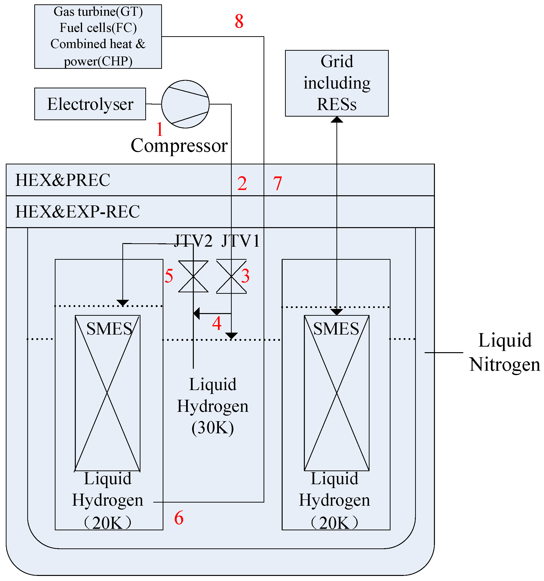
2. Liquid Hydrogen with Superconducting Magnetic Energy Storage (SMES)

The core of the energy internet in the future is the electric power system, combined with the natural gas network, transportation network and thermal network to form a comprehensive network. As shown in Figure 1, the LIQHYSMES can play an important role as the energy router in connecting, scheduling and controlling the networks concertedly in the future energy internet.
Figure 1 shows the structure of the hybrid energy storage device, which consists of three major parts: the electrochemical energy conversion (EEC), the LIQHYSMES storage unit (LSU) and the power conversion & control Unit (PCC). When a power fluctuation occurs as a result of the RES connected to the electric power system, it’s prone to cause a power imbalance and affect the stability of the electric power system.
To suppress the fluctuation rapidly, the PCC will control the SMES unit to charge or discharge depending on the supply and demand imbalance of the system, in which condition the energy is stored and released by means of electric energy. As shown in Figure 2, the SMES system has a DC magnetic coil that is connected to the AC grid through a power conversion system. Meanwhile, PCC will control the LH2 storage unit to work on the conversion of electric energy to achieve the slow suppression of the fluctuation. The surplus electric energy generated by the RESs can be converted into chemical energy by the electrolyser. Then, the gaseous hydrogen produced previously is liquefied into LH2 for storage. On the contrary, when a power shortage occurs in the electric power system, the liquid hydrogen stored in the liquid hydrogen tank is vaporized and supplied to the gas turbine (GT), fuel cells (FC), and combined heat & power (CHP) to supply electricity and heat to the electric power system and the thermal network, respectively.
The schematic of a LIQHYSMES device is shown in Figure 3. It includes a multi-stage compressor, two-stage heat exchangers (HEX), liquid nitrogen or multi-component refrigerants' pre-cooling (PREC), expansion turbines and gas recycling (EXP-REC), Joule-Thomson expansion valves (JTV), a LH2 storage tank and liquid nitrogen shielding. SMES based on coated conductors (based on high temperature superconductors, mostly YBaCuO and magnesium diboride (MgB2) superconducting wires [21,22]) is utilized here, which could be operated in the LH2 bath for sharing cooling system. In the charging process 1–4 shown in Figure 3, the gaseous hydrogen obtained after electrolysis is passed through a multistage compressor, heat exchangers and JTV1, so that most of the gaseous hydrogen is liquefied and stored in the LH2 tank at 10 bar and 30 K. Besides, a small amount of unliquefied gaseous hydrogen is fed to the JTV2 as a cooling medium for the SMES coil at 1.2 bar and 20 K, and subsequently supplied to the HEX and re-compressed for another expansion cycle. From the discharge process 5 to process 8, the LH2 stored in the LH2 tank is sent to JTV2. Then the LH2 is converted into gaseous hydrogen through the two HEX stages for use in GT, FC or CHP.
LIQHYSMES features the combined use of LH2 storage and SMES to stabilize power fluctuations in the electric power system with RES. The combined use of the SMES and liquid hydrogen can help to expand storage capacity substantially. On the other hand, the liquid hydrogen is used as cooling medium for the SMES and shares the refrigeration plant with it to enhance the refrigeration efficiency and reduce the investment cost.
The use of LIQHYSMES is not subject to strict geographical restrictions, and can be applied to a variety of voltage levels in the electric power system, which are of important significance for achieving large-scale use of RES.

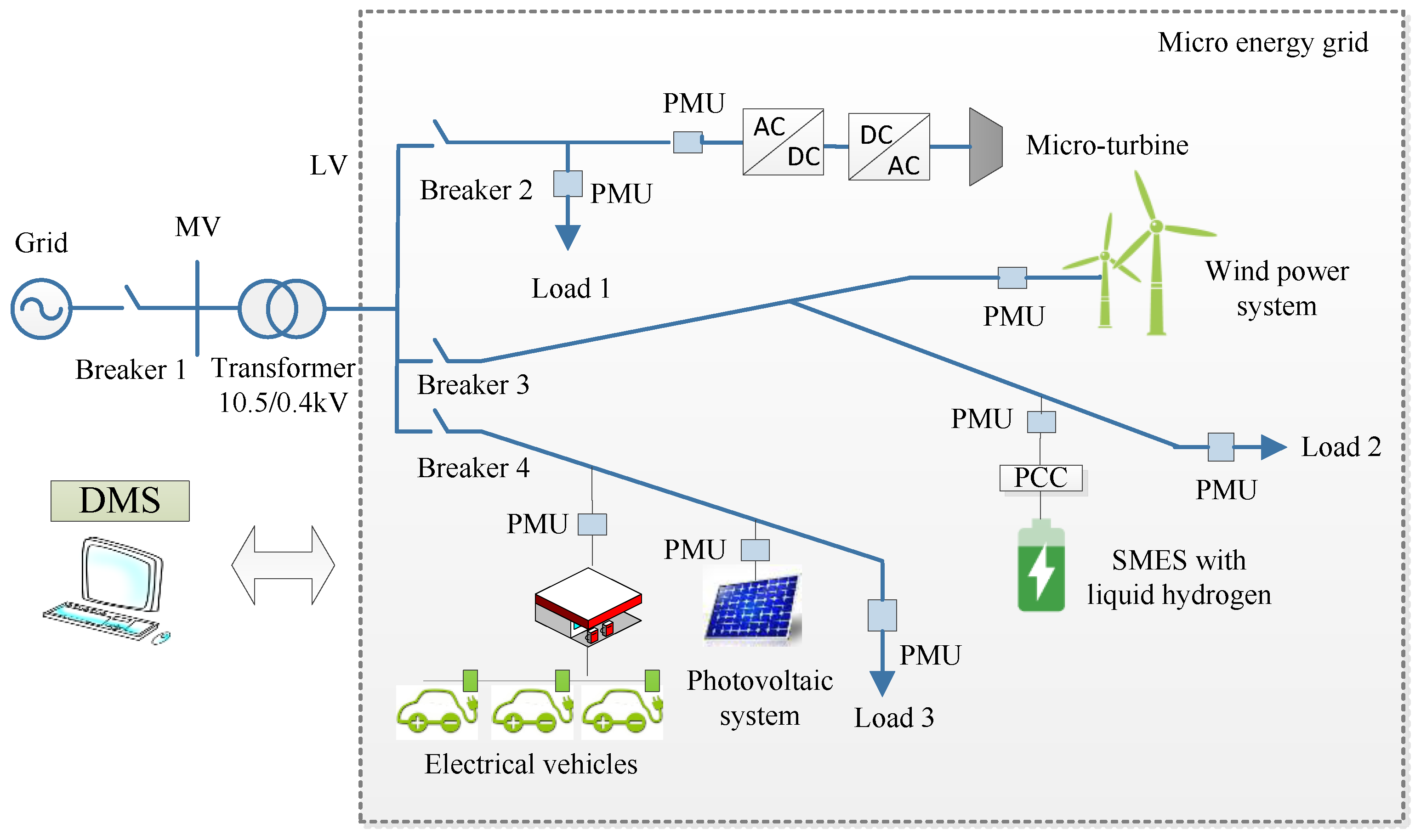
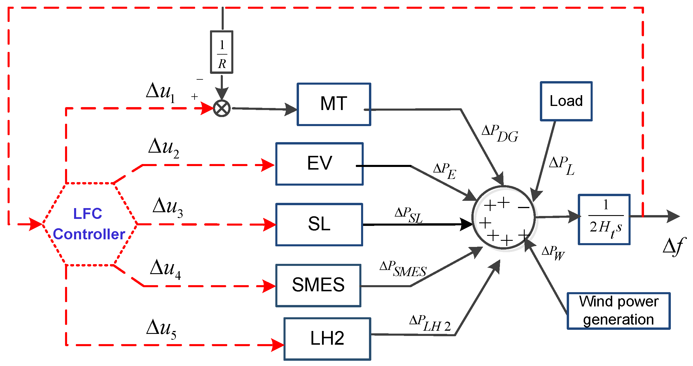
3. The Micro Energy Grid Including LIQHYSMES

The micro energy grid concept is consistent with the notion of the future electric power system, the characteristics of which will be profoundly different from those of the systems existing today. It represents the further development of microgrids. In a microgrid the energy is only transmitted in the form of electricity. However, in the micro energy grid with LIQHYSMES shown in Figure 1 the energy can be converted into electricity, chemical energy, thermal energy and other forms. The smart loads (SL) become controllable, and energy-storage systems, as well as vehicle-to-grid (V2G) systems, further contribute to active controllable loads. Renewable energy sources will thus be used more and more in homes, buildings, and factories [23].
The configuration architecture of the micro energy grid is presented in Figure 4. It is composed of a micro turbine (MT), DGs, an electrical vehicle station, smart loads and a LIQHYSMES unit. The micro energy grid is managed by a distribution management system (DMS). Phasor measurement units (PMUs) are installed in this micro energy grid to measure the real-time information of the components. A large number of data from PMUs can be handled by cloud computing in the DMS [24,25,26,27,28,29,30]. The micro energy grid is capable to work in either the grid-connected or isolated mode, transforming from one into the other by controlling the circuit breaker 1. In the grid-connected mode, the deviation of the frequency resulting from abrupt variations in load demand growth and generated power variations from different RESs can be eliminated rapidly by the electric power system to maintain stable operation. The isolated micro energy grid on the other hand needs to control the components coordinately to maintain the stability. With the LIQHYSMES, the system inertia could be increased, thus improving the frequency stability of the isolated micro energy internet. Here the equivalent model for LFC of the isolated micro energy grid is constructed.

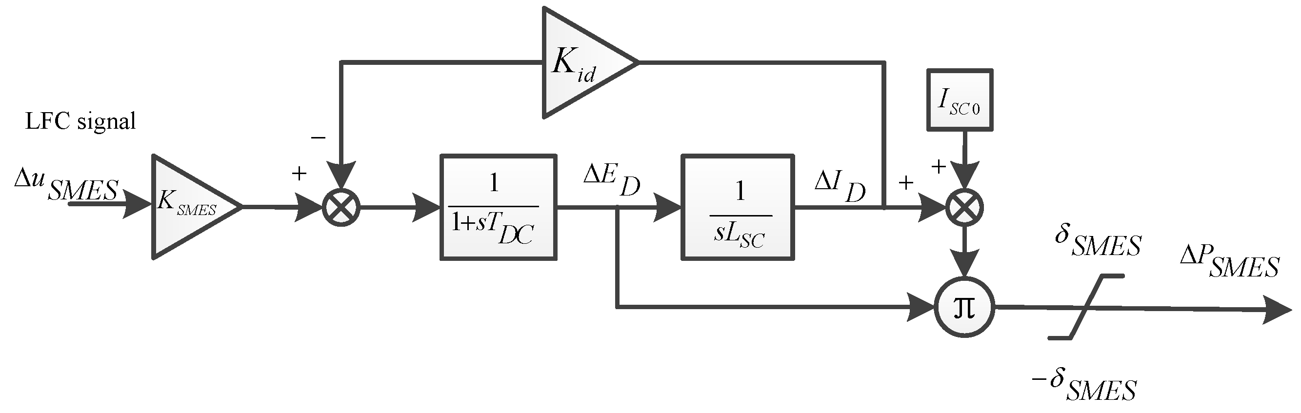
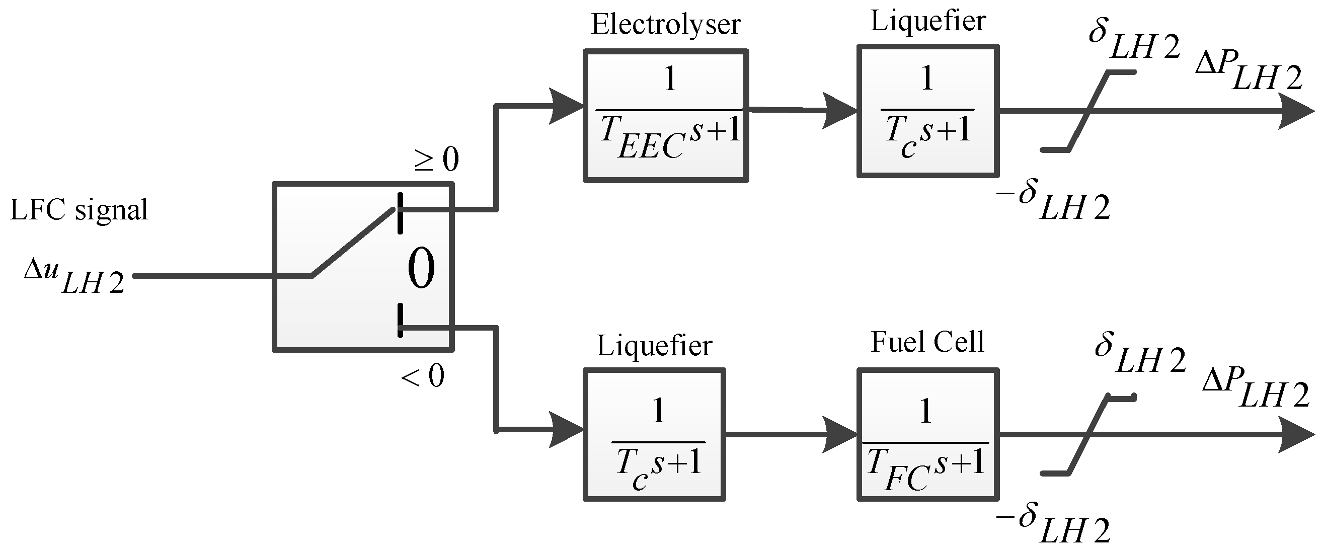
3.1. Model of LIQHSMES

During the LFC, the voltage and current of the superconducting coil vary with the frequency deviation to supply different amounts of power to maintain the stability of the system. When a disturbance disappears, the current of the superconducting coil should be restored to the initial value preparing for the subsequent disturbances.
The deviation of the superconducting coil (SC) voltage is given by:
Δ E d = K S M E S 1 + s T D C Δ f
The deviation of the SC current is expressed as:
Δ I d = Δ E d s L S C
The power supplying by the SMES can be obtained as follows:
Δ P S M E S = Δ E d ( I S C 0 + Δ I d )
Therefore, the model of the SMES in LFC can be represented as in Figure 5. Herein, the GPC algorithm proposed to be used in LFC is based on the controlled auto-regressive integrated moving-average (CARIMA) model. It can identify and linearize the model of the system online, so a feedback of the deviation of the SC current is added to eliminate the error caused by linearization and achieve rapid recovery of SC current meanwhile.
The power supplied by the LH2 storage unit and SMES to the micro energy grid are only controlled by PCC and are independent of each other, which means the two can be regarded as a common parallel system in the LFC. When the frequency deviation is negative, the controlled LH2 storage unit provides power to compensate the power shortage by using the FC, GT or CHP. When the frequency deviation is positive, the LH2 storage unit utilizes the electrolyser for consumption of excess power. The model of the LH2 storage unit for LFC is shown in Figure 6. Here, the FC is used as the device to convert the LH2 into electric energy. The FC constant time is set as same as the electrolyser time constant to simplify the model used in this paper.

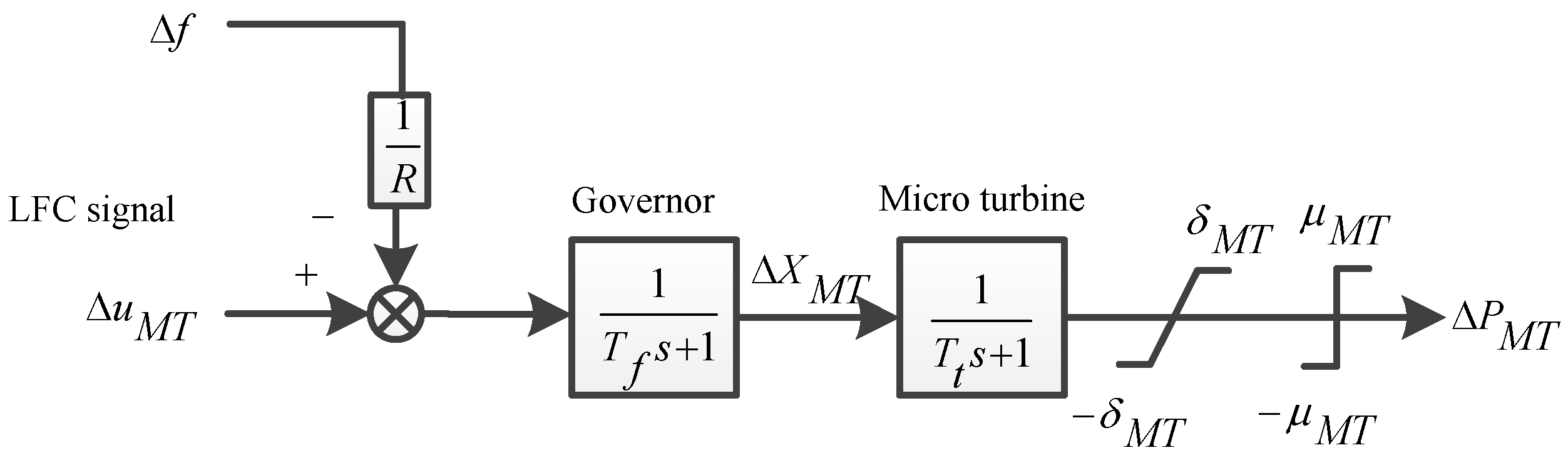
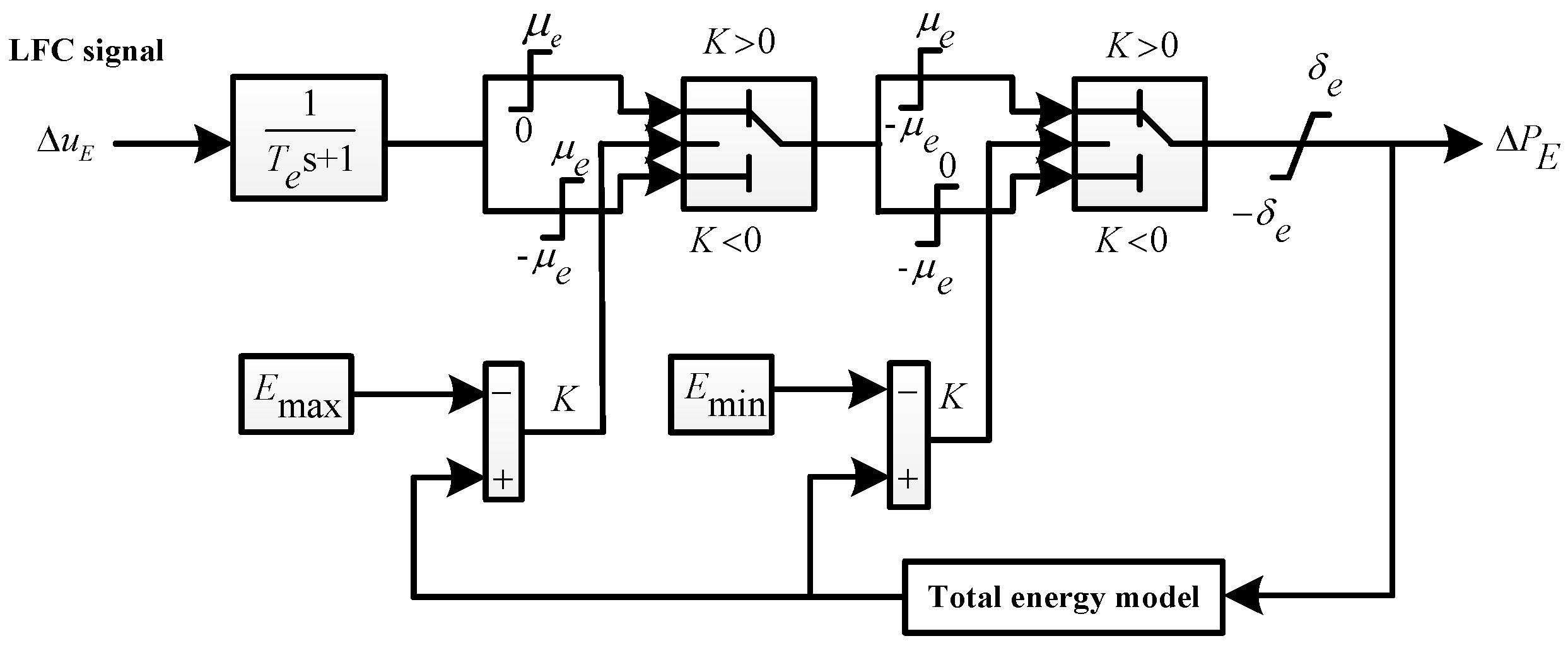
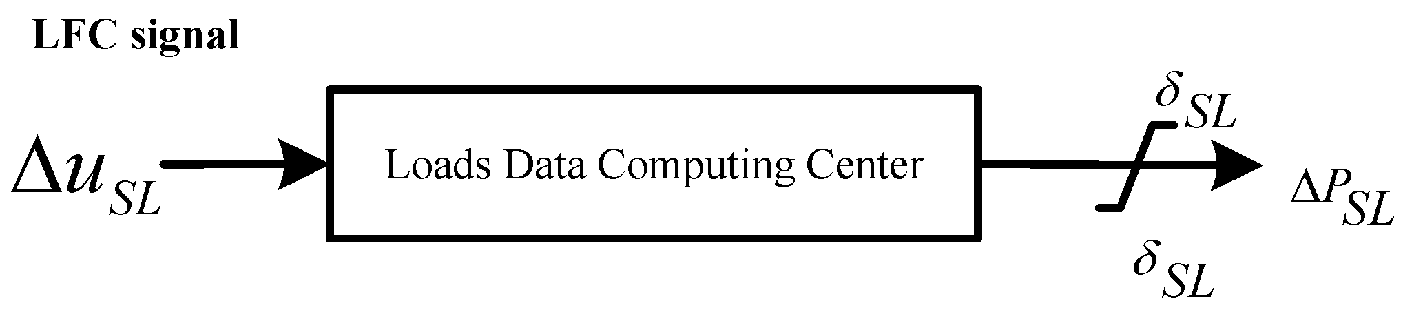
3.2. Models of Other Components

Figure 7 shows the model of a micro-turbine for LFC, which simulates the dynamic process of the micro-turbine output power following the LFC signal. The model includes the governor, fuel system and gas turbine of the micro-turbine. The equivalent models of the fuel system and the turbine are represented by the first-order inertia units.
Since there are different numbers of EVs in each EV station, the modelling of EVs could be handled by using equivalent EVs with different inverter capacities. The equivalent EV model which can be used for LFC is shown in Figure 8 [31]. The EV can be charged and discharged only within the range of ± μ e . However, if the energy of the EV exceeds the upper limit (i.e., Emax), the EV can only be discharged within the range of (0~ μ e ). Also, if the energy of the EV is smaller than the lower limit (i.e., Emin), the EV can only be charged within the range of ( μ e ~0). T e is the time constant of EV.
In the micro energy internet, the loads data computing center can calculate the total supplied power depending on the frequency deviation. Subsequently, it adjusts the amount of smart loads in need of being open or closed, although the output power of each smart load is uncontrollable. Smart loads have the advantage of rapid response for LFC and the model is shown in Figure 9.
Because the fluctuation of wind power and photovoltaic (PV) power output is relatively large, they can be all equalized to the disturbance sources in the LFC model [32]. The power disturbances of wind have similar responses to PV systems in the LFC model, so it is only considered here.
Based on the LFC response models of the above-mentioned components, a model of micro energy network including LIQHYSMES with load frequency controller for LFC is constructed as shown in Figure 10. Δ P L is the load disturbance, Δ P W is the fluctuation of the wind power generation, and H t is the inertia constant of the micro energy internet.

4. Generalized Predictive Control Algorithm for LFC

The principle of the GPC algorithm can be summarized as three parts: predictive model, rolling optimization and feedback compensation. In the GPC algorithm, the predictive model is described by the CARIMA model, which is suitable for unstable system and is easier to be recognized online. The LFC signals shown in Figure 10 are the multiple inputs and the frequency deviation is the single output of the predictive model. Also, the unmeasured disturbance caused by load disturbance or the fluctuation of wind power generation and measurable noise are taken into account in the model. The predictive model can be described as follows:
A ( z 1 ) Δ f ( t ) = i = 1 5 B i ( z 1 ) Δ u i + D ( z 1 ) w ( t ) + ξ ( t ) / Δ
where t is the discrete sampling time point of control, Δ u i is the LFC signal for each component in Figure 10, z 1 is the backward shift operator. Δ = 1 z 1 is the difference operator, which represents the effect of random noise. ξ ( t ) is a n-dimensional zero mean white noise sequence. A ( z 1 ) , B ( z 1 ) , D ( z 1 ) are the polynomial matrixes of z 1 :
{ A ( z 1 ) = I n × n + a 1 z 1 + a 2 z 2 + + a n a z n a B i ( z 1 ) = b i 0 + b i 1 z 1 + b i 2 z 2 + + b i n b z n b D ( z 1 ) = d 0 + d 1 z 1 + d 2 z 2 + + d n d z n d
where a 1 , a 2 …, b i 1 , b i 2 … and d 1 , d 2 … are the polynomial coefficients, n a , n b , n d are the orders of the polynomial, respectively. n a is the prediction time domain, n b is the control time domain, where the first term can be 0, denoting the number of time delays of the response, and n d is the interference time domain.
In order to track the set reference value w ( t + j ) of the predicted output, we can calculate the control vectors using optimization techniques based on the following objective function:
J = j = 1 n a | | Δ f ( t + j | t ) w ( t + j ) | | Q 2 + i = 1 5 ( j = 1 n b | | Δ u i ( t + j 1 ) | | R 2 )
where Q and R are the positive definite weighting matrixes, Δ f ( t + j | t ) is an optimal j -step prediction of the frequency deviation at time t. The reference value w ( t + j ) of the j -step frequency deviation is set as constant 0. The control vectors can be obtained by many algorithms to solve this quadratic programming problem, such as sequential minimal optimization (SMO) [33,34,35,36,37]. Herein, the function ’quadprog’ provided by Matlab is used and the first row of the vectors Δ u ( t | t ) is carried out as the LFC signals to eliminate the frequency deviation at the sampling time point t .
In the GPC algorithm, the recursive least squares method is used to identify the parameters of the predictive model for the LFC in the micro energy internet, which means that the polynomial matrixes A ( z 1 ) , B ( z 1 ) , C ( z 1 ) vary with the sampling time. Then the optimal control sequence can be calculated. This online identification and the control sequence correction mechanism constitute the GPC algorithm feedback correction.

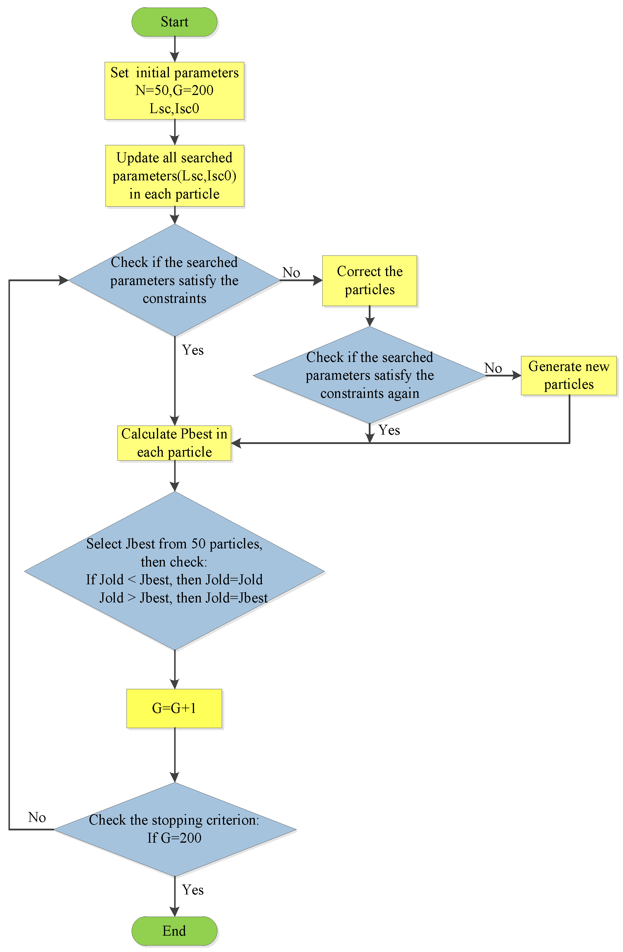
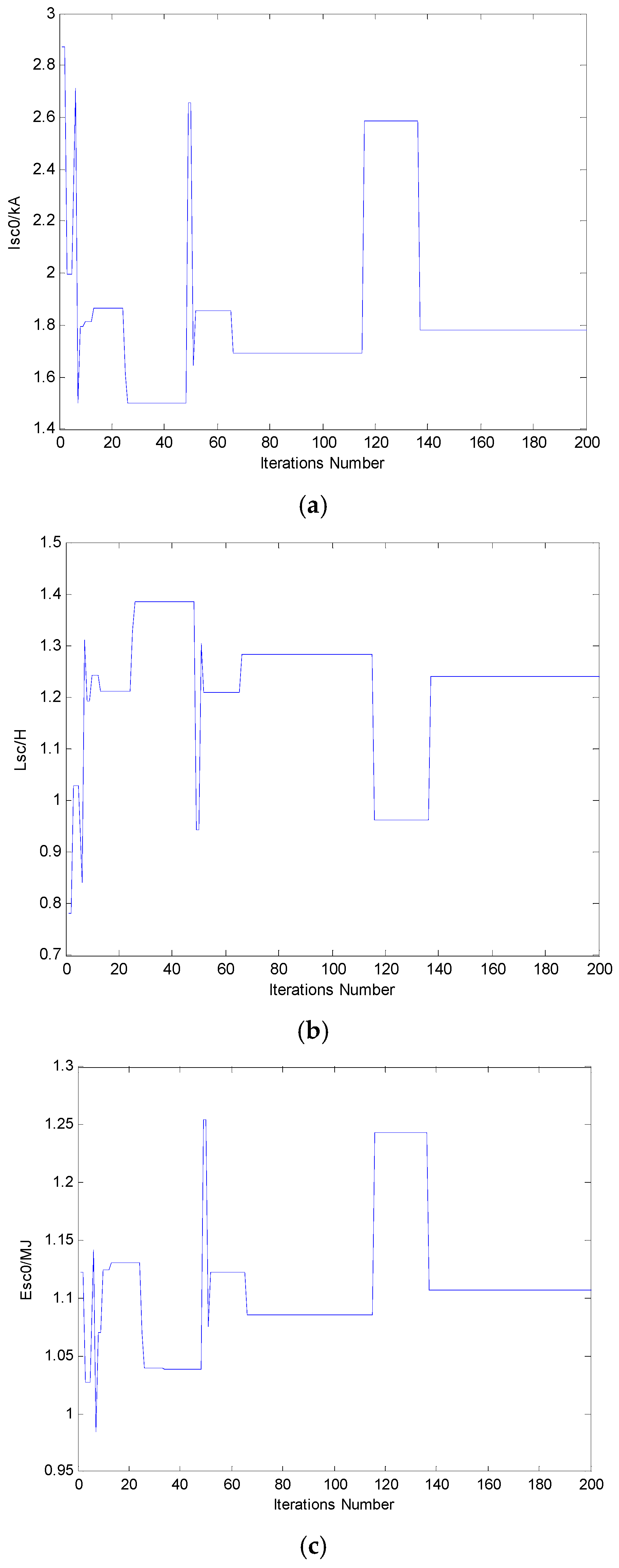
5. The Optimization Design of the Superconducting Coil
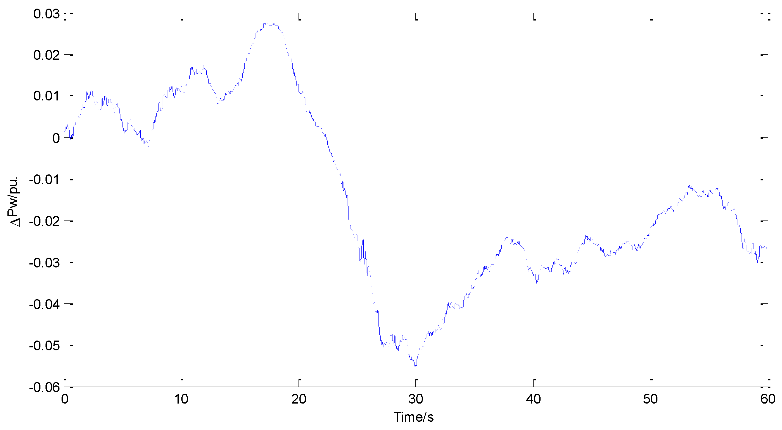
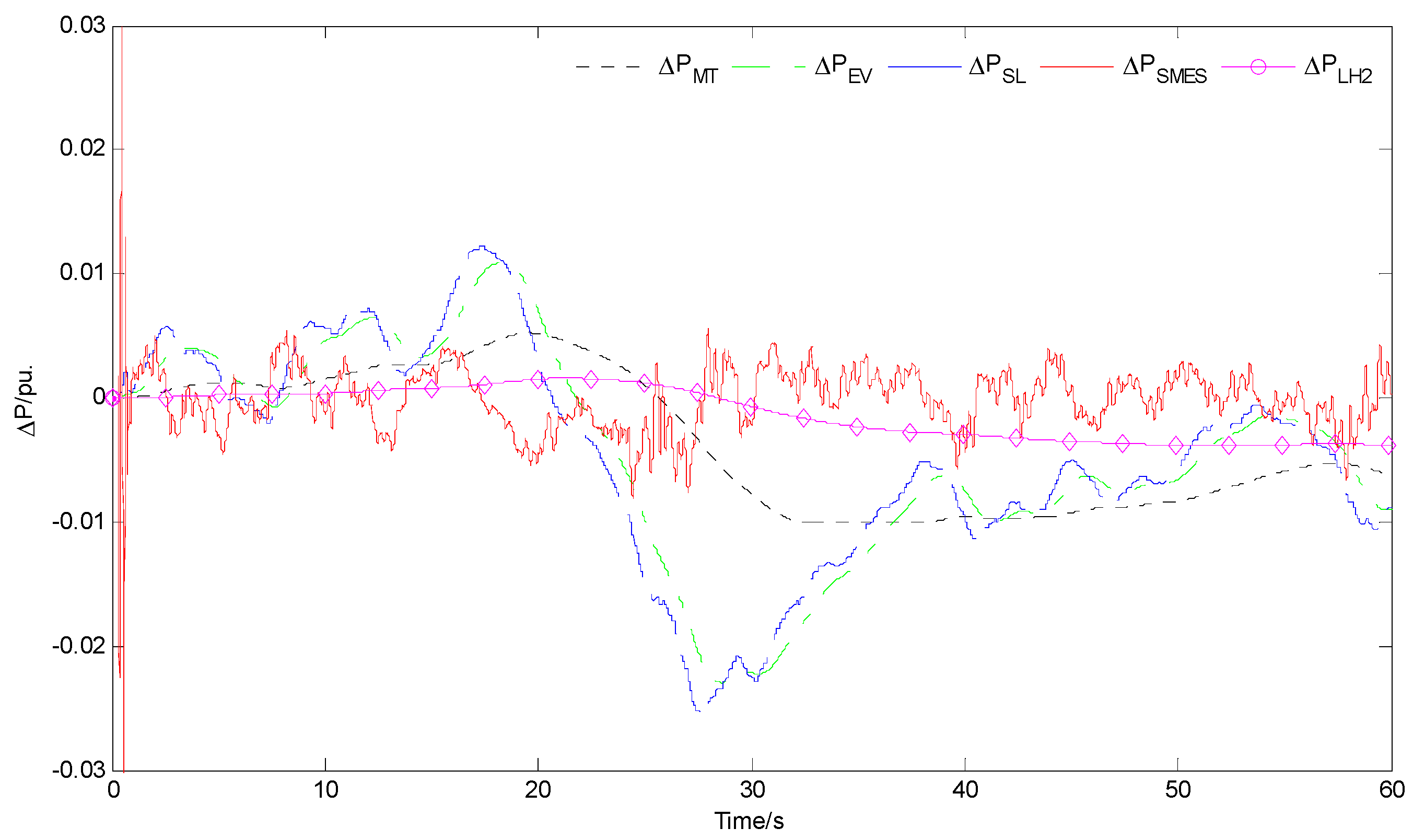
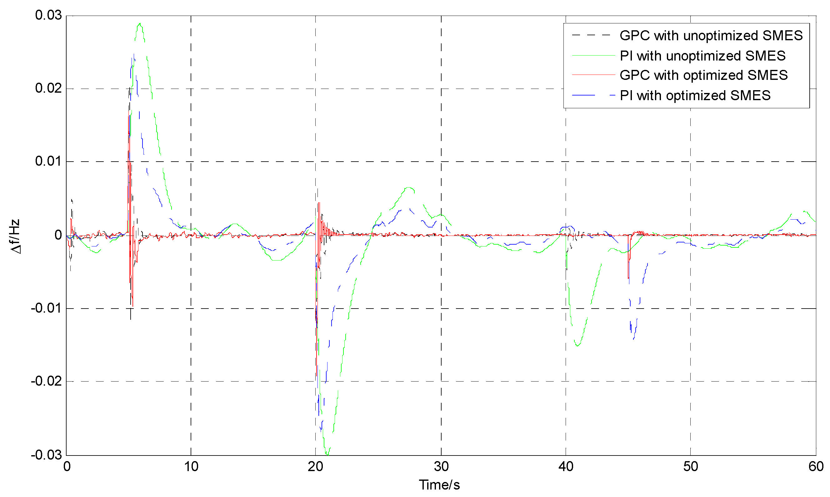
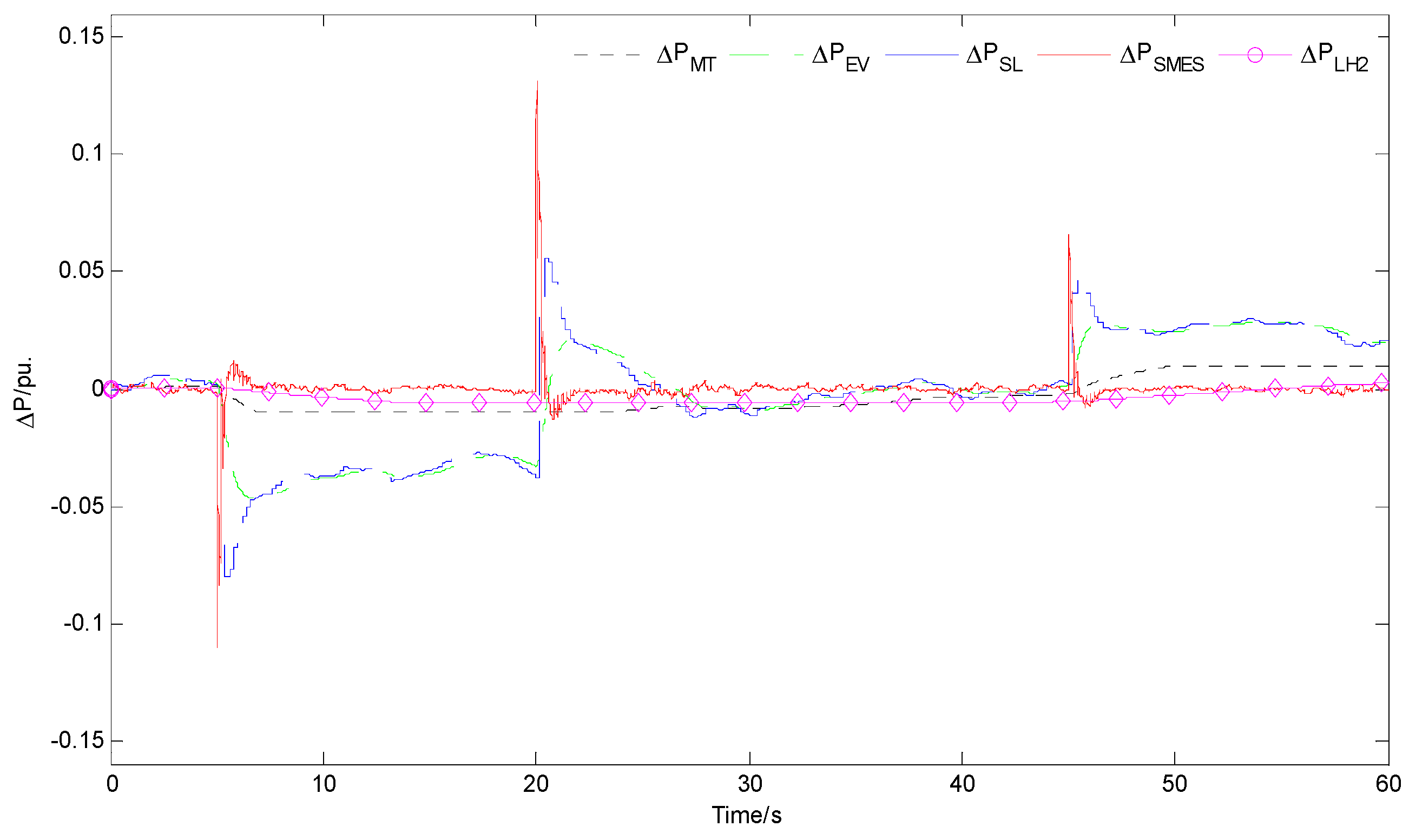
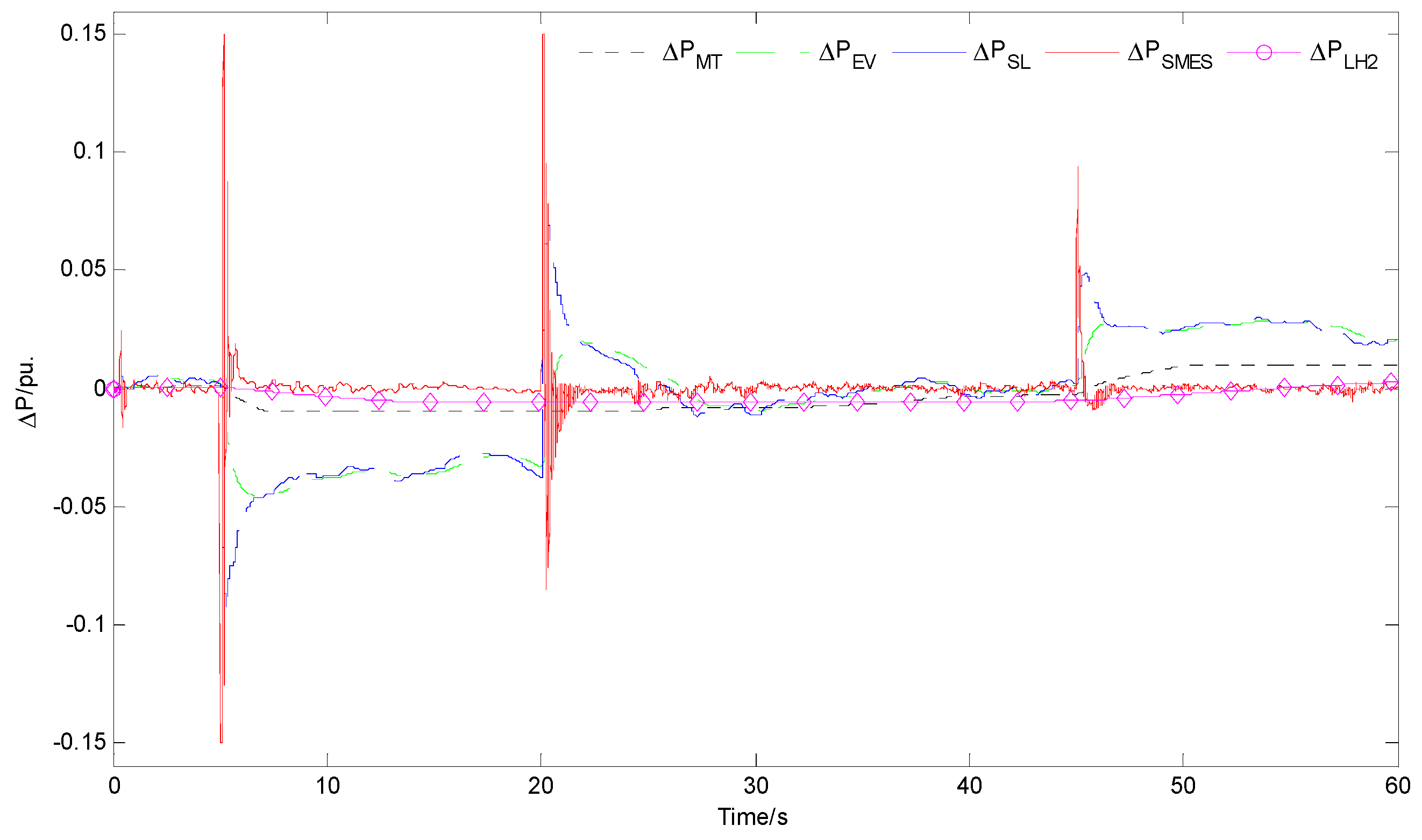
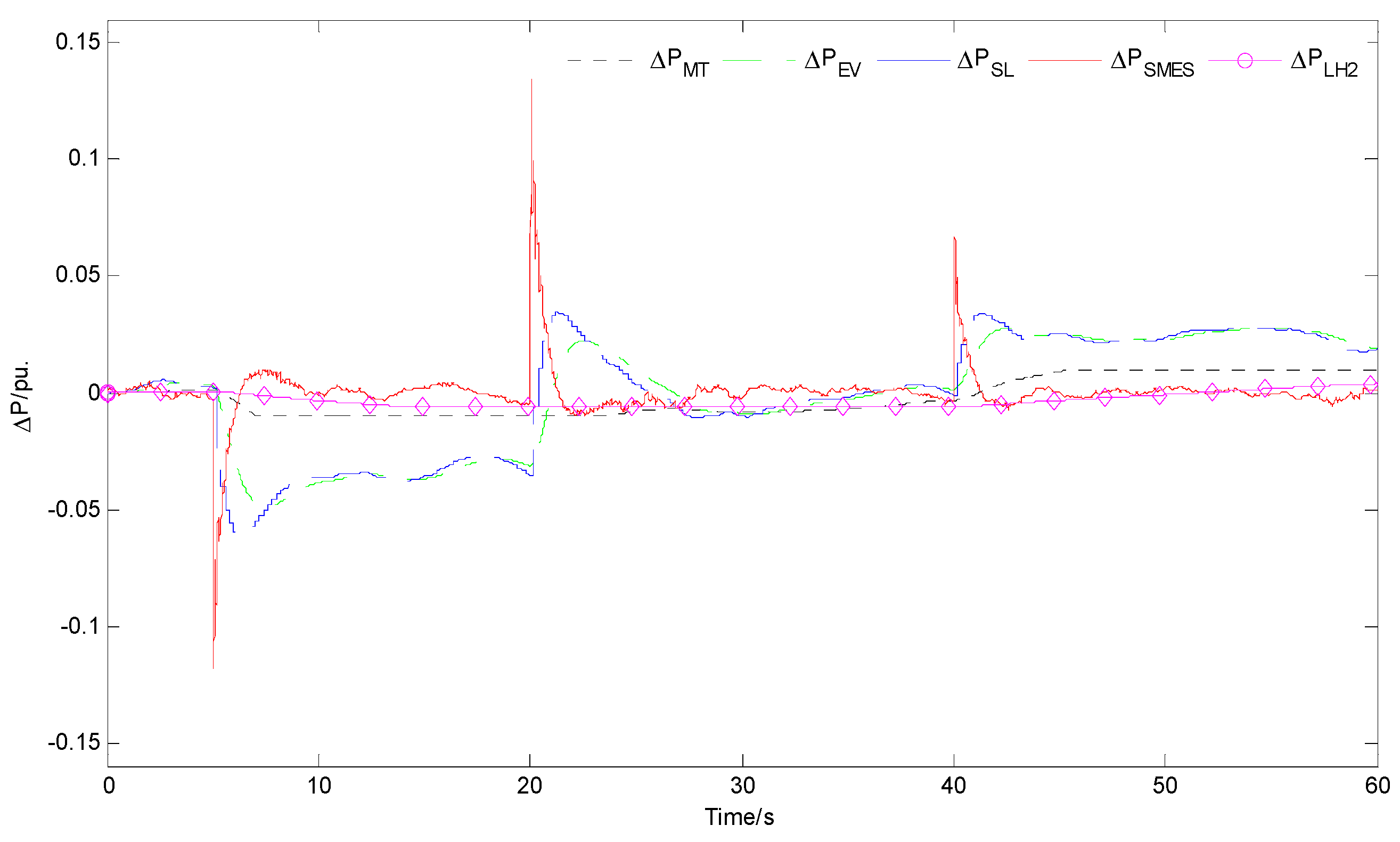
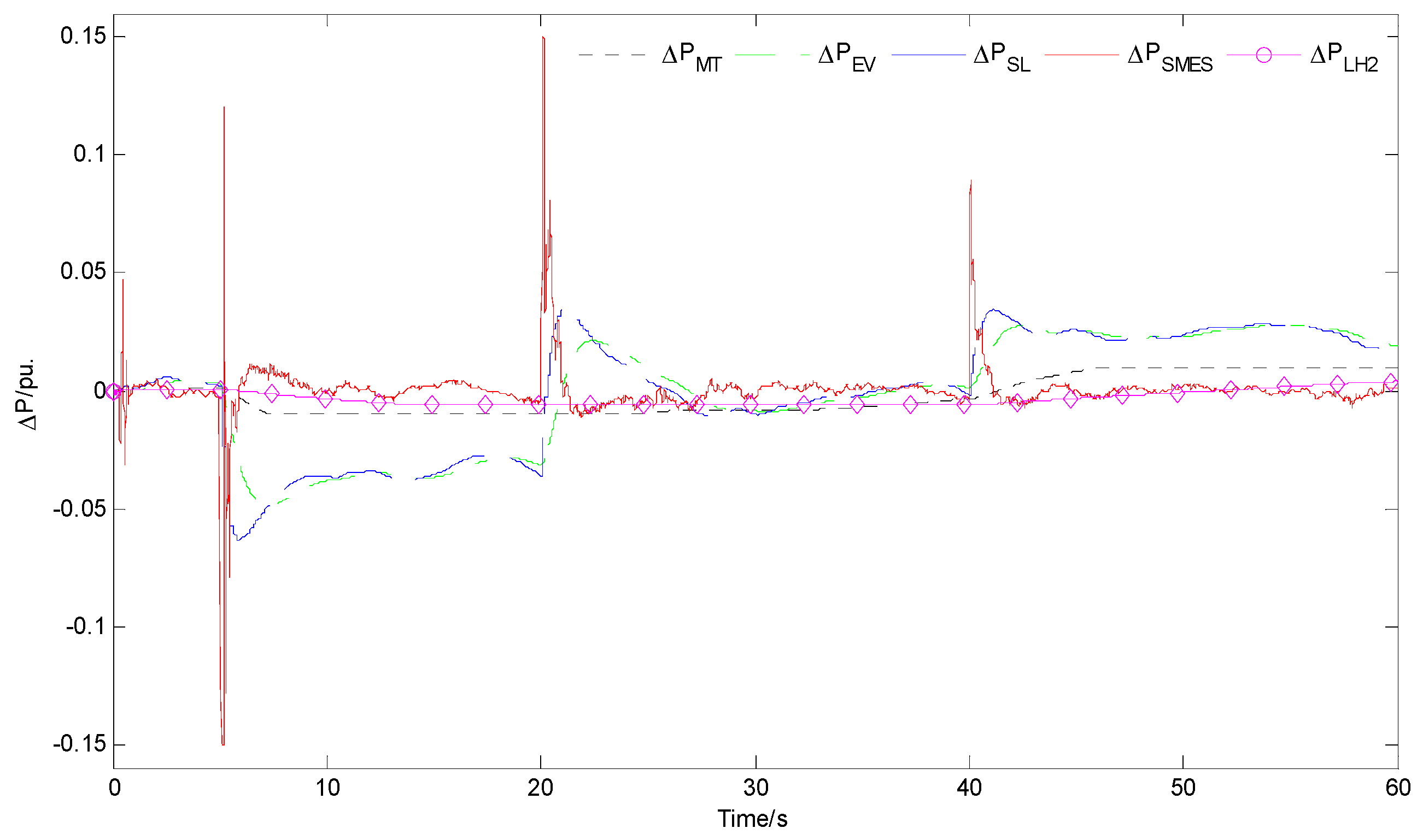
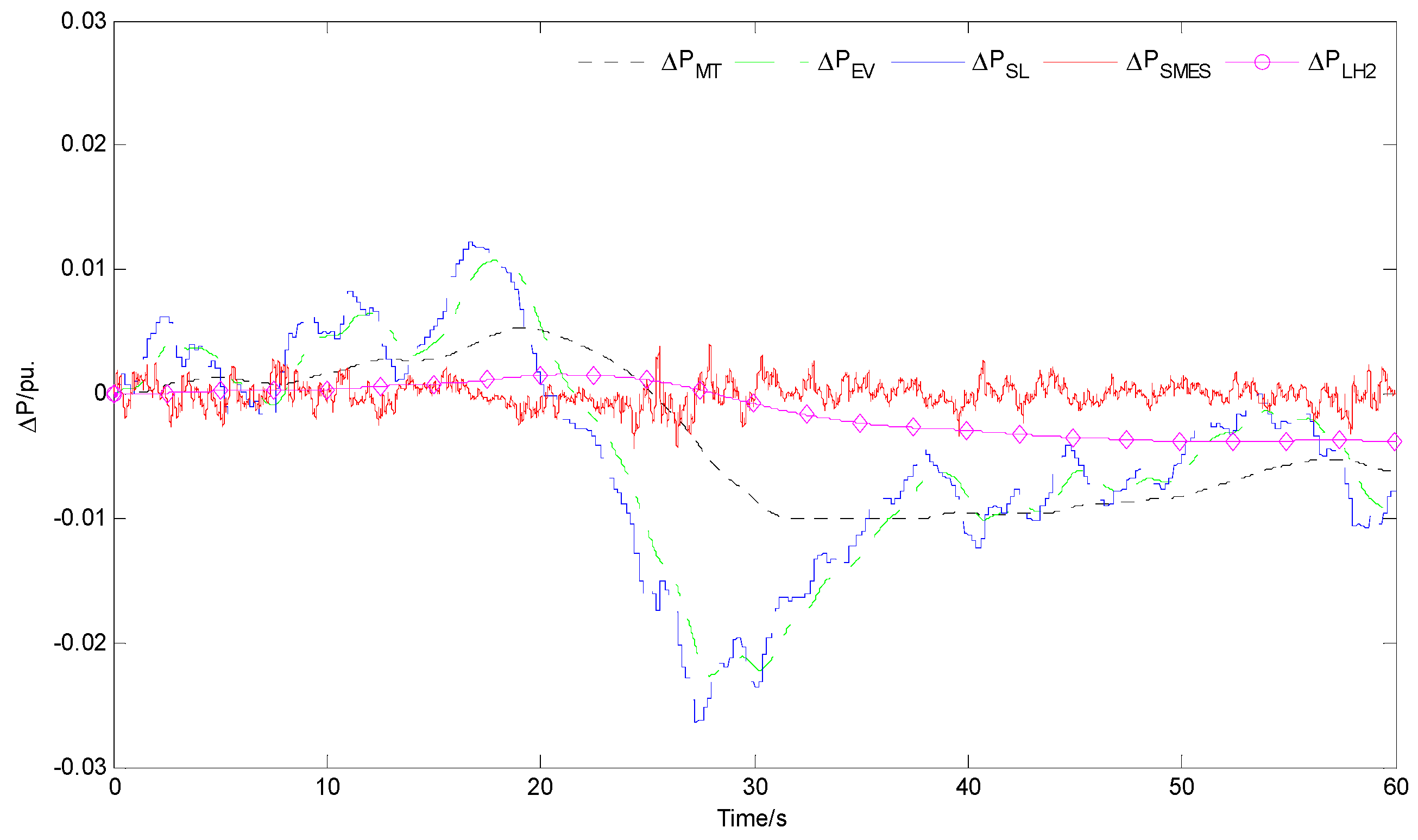
The SC parameters, e.g., initial current I S C 0 , coil inductance L S C and initial stored energy E s c 0 , are optimized to improve the control effect of the LFC model for the micro energy internet. In order to improve the stability, the following objective function can be used:
Min   J 1 = 0 t s i m | Δ f | d t
where t s i m is the total simulation time.
Δ f ( s ) = ( Δ P M T ( s ) + Δ P E V ( s ) + Δ P S L ( s ) + Δ P S M E S ( s ) + Δ P L H 2 ( s ) Δ D ) 1 2 H t s
Δ D is the system uncertainty model which represents several operating conditions of unpredictable wind power and loads variation.
The response of SMES is expressed as:
P S M E S ( s ) = ( R ( s ) s L S C ( 1 + s T D C ) + 1 + I S C 0 s ) ( s L S C R ( s ) s L S C ( 1 + s T D C ) + 1 )
The input signal R ( s ) is the load frequency control signal. Also the responses of other components can be expressed as the form of SMES so that the response of the frequency deviation can be obtained. Then, the numerical inversion of Laplace transform is employed for the time domain response of the frequency deviation.
Moreover, the initial stored energy is given by:
E s c 0 = 1 2 L S C I S C 0 2
To optimize the E s c 0 , the optimal L S C and I S C 0 is obtained by taking it into consideration. The above two parts are weighted linearly, so the optimization problem can be formulated as follows:
Min   J = W 1 J 1 + W 2 E S C 0
Subject to:
0.001 L S C 10 H
1.5 I S C 0 4 k A
where the weighting factors are set as W 1 = 1 , W 2 = 0.01 in this paper. Then the particle swarm optimization (PSO) is applied to solve the problem. Figure 11 shows the flowchart of PSO [38].

6. Simulation Study

Simulations are carried out based on the above-mentioned model of micro energy grid, and the model parameters are shown in Table 1. Some of the values are chosen referring to [20]. Suppose that the micro energy grid is in steady isolated state at the beginning of the simulation. The wind power from an offshore wind farm in Denmark is shown in Figure 12, where Δ P W = 0 means the wind power is equal to the average power during the period.
As shown in Figure 13, it can be concluded that the frequency response of the system is better under the control of the GPC algorithm proposed in this paper than PI during the simulation period, except for the initial moment. The frequency deviation of the system is controlled generally within the range of ±0.002 Hz with LIQHYSMES, which shows that the controller based on the GPC algorithm offers better stability and robustness. The frequency oscillation is smoother and the range is smaller with the LIQHYSMES unit compared with the conditions without it. It can be seen that the LIQHYSMES unit plays a positive role in suppressing the oscillation of the load frequency caused by wind power fluctuation in an isolated micro energy grid.
At the initial moment of the simulation, the PI control is more effective than the GPC algorithm, because there is little historical data provided for the online identification of the system predictive model parameters causing the large prediction deviations and the remarkable frequency fluctuations. Actually this situation can be avoided by providing historical inputs and outputs data on the parameters of the predictive model to be pre-set before the simulation.
Figure 14 and Figure 15 show the active output power of the components of the micro energy grid controlled by the two methods. SMES has the ability to respond quickly to the frequency oscillation, while the response speed of the LH2 storage unit is slower due to its larger inertia. Since the output power of each smart load is not adjustable, the total active output power of the smart loads can’t change smoothly. In addition, electric vehicles based on V2G technology can also be used as energy storage devices to participate in the system of load frequency control.
For an isolated micro energy grid with RESs, the abrupt change in load demand is also a challenge for the system to maintain frequency stability. Assuming that there are step disturbances in load demand (ΔPL = −0.1 pu, ΔPL = 0.12 pu, and ΔPL = 0.06 pu at t = 5 s, t = 40 s and t = 80 s, respectively). The fluctuation of the wind power is added to obtain the combined power disturbances shown in Figure 16.
Figure 17 shows the frequency deviation results when PI control and GPC algorithm are applied to the LFC. Comparing with PI control, GPC can suppress the frequency oscillation more rapidly and the peak of it is also smaller with or without the LIQHYSMES unit. In the case with LIQHYSMES unit, the advantage of the proposed GPC algorithm in suppressing the frequency oscillation is more obvious. Figure 18 and Figure 19 show the active power contribution of the various components of the system. In the event of abrupt change in load demand, SMES can provide or consume power from the system in response to a rapid change in load frequency.
Based on the PSO algorithm, the superconducting coil parameters of LIQHYSMES are optimized, and the iterative process of optimization is shown in Figure 20. The number of particles is set as 50 and the number of the iterations is set as 200. Here, the input signal R(s) is chosen as a step signal with the amplitude of 0.1.
The optimized LIQHYSMES unit is applied to the load frequency control of the micro energy grid, and the performance of the non-optimized LIQHYSMES unit is compared in Table 2.
As shown in Figure 21 and Figure 22, the system with optimized SC is able to maintain better frequency stability when different load disturbances occur. As the wind power fluctuating, the output power of SMES unit with optimized SC increases comparing with the non-optimized SC controlled by the two methods as shown in Figure 23 and Figure 24. The tendency is the same in the case with the combined disturbances as shown in Figure 25 and Figure 26.
The proposed GPC algorithm utilizes CARIMA that features an easy online identification. Meanwhile, it can improve the robustness of the controller. However, as the high penetration rate of the DGs in the energy internet, CARIMA may result in prediction deviations for the LFC. Therefore, it is necessary to have stochastic studies with given confidence interval in this condition.

7. Conclusions

Energy storage devices are necessary in the energy internet due to an increasing number of RESs are adopted in the future. The LIQHYSMES unit can obtain better economic benefits with promising applications. The LFC controller based on GPC algorithm is designed and applied to the micro grid energy including the LIQHYSMES unit. To obtain better control effect, the SC parameters are optimized as well. Simulations of the load frequency control based on the equivalent model of the micro grid energy are carried out and the results are summarized as follows.
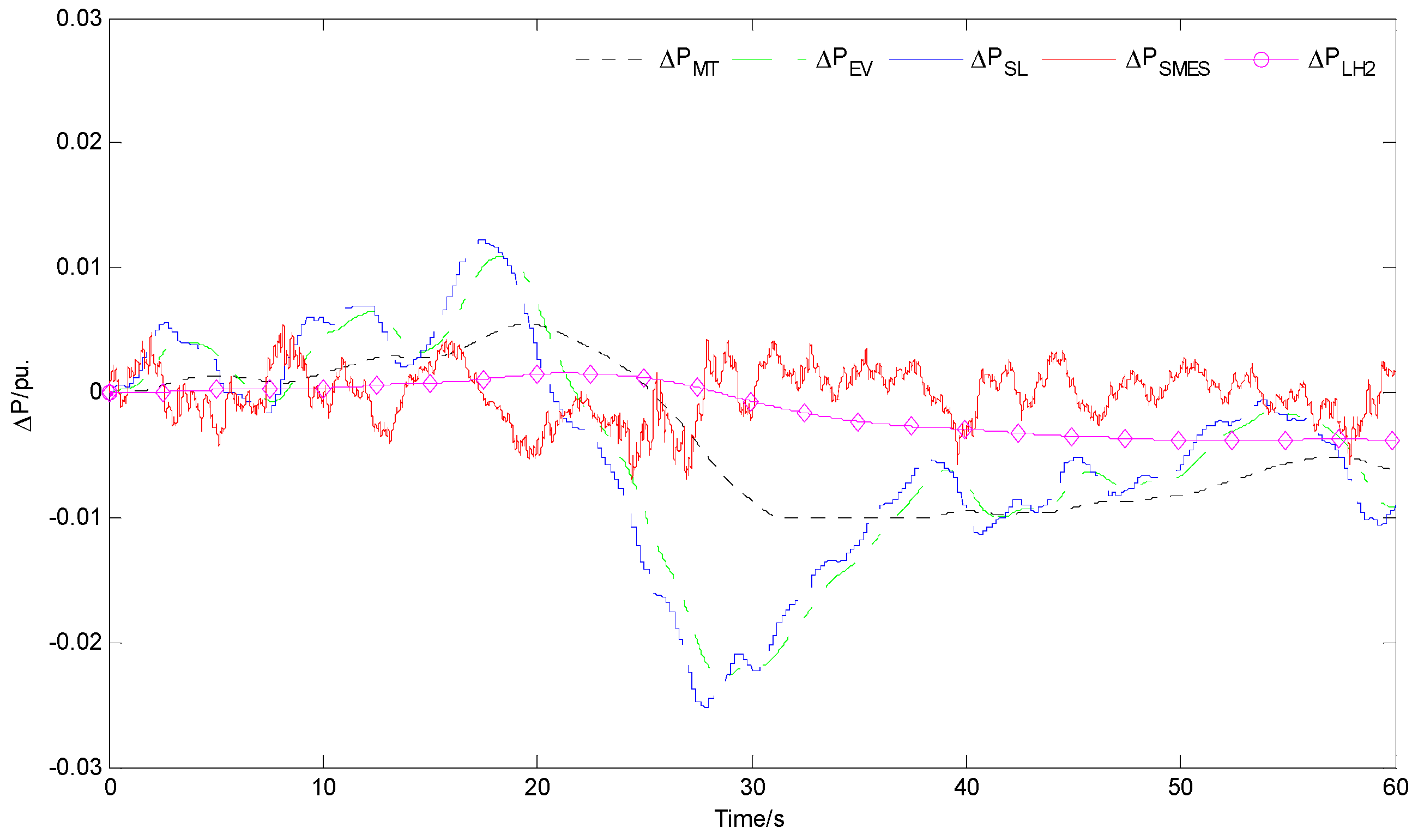
  • The LIQHYSMES unit can be used to achieve the energy storage and transformation in the energy internet. It is also helpful for the efficient use of renewable energy through solving the frequency instability problems of the isolated micro energy grid.
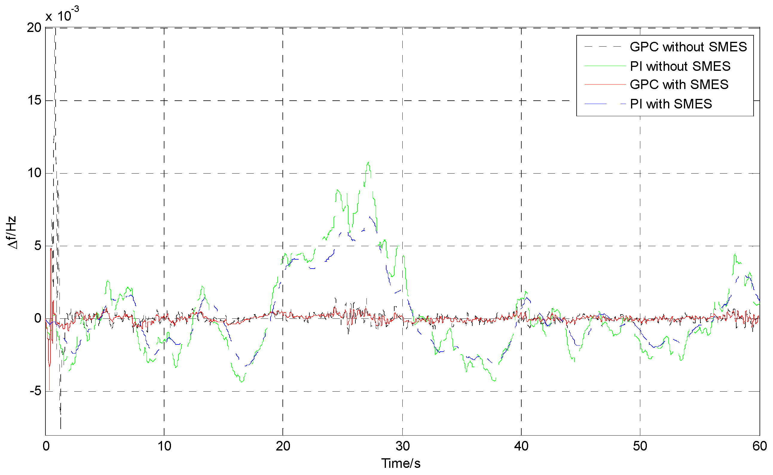
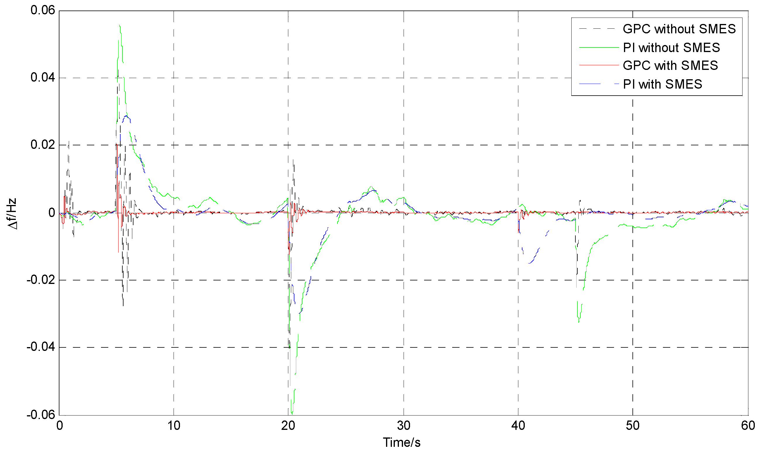
  • In the isolated micro energy grid including the LIQHYSMES unit, the proposed controller based on GPC algorithm can obtain better robust performance on LFC in complex operation situations, namely, random renewable energy generations and continuous load disturbances. It plays a significant role in the load frequency control, especially in the cases where the load demand changes violently in the system with RESs.
  • The optimization SC parameters of the SMES can offer better technical advantages in alleviating the load frequency fluctuations in different cases.
For the future work, an experimental study which implements the proposed method in reality will be carried out.

Acknowledgments

The work is funded by the National Science Foundation of China (51277135, 50707021).

Author Contributions

Jun Yang and Xin Wang conceived and designed the study; Xin Wang performed the experiments; Lei Chen analyzed the experimental results; Jifeng He contributed analysis tools; Xin Wang and Jun Yang wrote the paper.

Conflicts of Interest

The authors declare no conflict of interest.

Nomenclature

Δ D Unpredictable wind power and loads variation T D C Converter time constant
T E E C Electrolyser time constant
Δ E d Deviation of the SC voltage T c Liquefier time constant
E S C 0 Initial stored energy of SC T F C FC time constant
E max Maximum controllable energy T f Governor time constant
E min Minimum controllable energy T t Generator time constant
Δ f Deviation of the frequency T e EV time constant
H t Gird inertia Δ u M T LFC signal for MT
Δ I d Deviation of the SC current Δ u 1
I S C 0 Initial current of SC Δ u E LFC signal for EV
J 1 , J Objective functions Δ u 2
K S M E S Gain of the SMES Δ u S L LFC signal for SL
K i d Gain of the feedback in SMES Δ u 3
L S C Coil inductance of SC Δ u S M E S LFC signal for SMES
n a Prediction time domain Δ u 4
n b Control time domain Δ u L H 2 LFC signal for LH2 storage unit
n d Interference time domain Δ u 5
Δ P S M E S Output power increment of SMES δ S M E S Power ramp rate limit of SMES
Δ P L H 2 Output power increment of LH2 storage unit δ L H 2 Power ramp rate limit of LH2 storage unit
Δ P M T Output power increment of MT δ M T Power ramp rate limit of MT
Δ P E Output power increment of EV δ e Power ramp rate limit of EV
Δ P S L Output power increment of SL δ S L Power ramp rate limit of SL
Δ P L Load disturbance μ M T Power increment limit of MT
Δ P W Fluctuation of the wind power generation μ e Inverter capacity limit of EV
W 1 , W 2 Weighting factors
R Speed regulation of MT Δ X M T Valve position increment of the governor
R ( s ) Input signal of LFC
t s i m Total simulation time ξ ( t ) White noise sequence

References

  1. Carrasco, J.M.; Franquelo, L.G.; Bialasiewicz, J.T.; Galván, E.; Guisado, R.C.P.; Prats, M.Á.M.; León, J.I. Power-electronic systems for the grid integration of renewable energy sources: A survey. IEEE Trans. Ind. Electron. 2006, 53, 1002–1016. [Google Scholar] [CrossRef]
  2. Georgiou, P.N.; Mavrotas, G.; Diakoulaki, D. The effect of islands’ interconnection to the mainland system on the development of renewable energy sources in the Greek power sector. Renew. Sustain. Energy Rev. 2011, 15, 2607–2620. [Google Scholar] [CrossRef]
  3. Sun, Q.; Zhang, Y.; He, H.; Ma, D.; Zhang, H. A novel energy function-based stability evaluation and nonlinear control approach for energy internet. IEEE Trans. Smart Grid 2015, PP, 1–16. [Google Scholar] [CrossRef]
  4. Huang, A.Q.; Crow, M.L.; Heydt, G.T.; Zheng, J.P.; Dale, S.J. The future renewable electric energy delivery and management (FREEDM) system: The energy internet. Proc. IEEE 2010, 99, 133–148. [Google Scholar] [CrossRef]
  5. Zhou, K.; Yang, S.; Shao, Z. Energy internet: The business perspective. Appl. Energy 2016, 178, 212–222. [Google Scholar] [CrossRef]
  6. Palizban, O.; Kauhaniemi, K. Energy storage systems in modern grids—Matrix of technologies and applications. J. Energy Storage 2016, 6, 248–259. [Google Scholar] [CrossRef]
  7. Yang, J.; Zhang, L.; Wang, X.; Chen, L.; Chen, Y. The impact of SFCL and SMES integration on the distance relay. Phys. C Supercond. Its Appl. 2016, 530, 151–159. [Google Scholar] [CrossRef]
  8. Hirano, N.; Watanabe, T.; Nagaya, S. Development of cooling technologies for SMES. Cryogenics 2016, 80, 210–214. [Google Scholar] [CrossRef]
  9. Yang, W.J.; Aydin, O. Wind energy–hydrogen storage hybrid power generation. Int. J. Energy Res. 2001, 25, 449–463. [Google Scholar] [CrossRef]
  10. Hirabayashi, H.; Makida, Y.; Nomura, S.; Shintomi, T. Liquid hydrogen cooled superconducting magnet and energy storage. IEEE Trans. Appl. Supercond. 2008, 18, 766–769. [Google Scholar] [CrossRef]
  11. Nakayama, T.; Yagai, T.; Tsuda, M.; Hamajima, T. Micro power grid system with SMES and superconducting cable modules cooled by liquid hydrogen. IEEE Trans. Appl. Supercond. 2009, 19, 2062–2065. [Google Scholar] [CrossRef]
  12. Hirabayashi, H.; Makida, Y.; Nomura, S.; Shintomi, T. Feasibility of hydrogen cooled superconducting magnets. IEEE Trans. Appl. Supercond. 2006, 16, 1435–1438. [Google Scholar] [CrossRef]
  13. Sander, M.; Gehring, R. LIQHYSMES—A novel energy storage concept for variable renewable energy sources using hydrogen and SMES. IEEE Trans. Appl. Supercond. 2011, 21, 1362–1366. [Google Scholar] [CrossRef]
  14. Sander, M.; Gehring, R.; Neumann, H. LIQHYSMES—A 48 GJ toroidal MgB2-SMES for buffering minute and second fluctuations. IEEE Trans. Appl. Supercond. 2013, 23, 5700505. [Google Scholar] [CrossRef]
  15. Sander, M.; Neumann, H. LIQHYSMES—Size, loss and cost considerations for the SMES—A conceptual analysis. Supercond. Sci. Technol. 2011, 24, 105008–105013. [Google Scholar] [CrossRef]
  16. Vachirasricirikul, S.; Ngamroo, I. Robust LFC in a smart grid with wind power penetration by coordinated v2g control and frequency controller. IEEE Trans. Smart Grid 2014, 5, 371–380. [Google Scholar] [CrossRef]
  17. Shankar, G.; Lakshmi, S. Frequency control of hybrid renewable energy system with PSO optimized controller. In Proceedings of the 2015 International Conference on Recent Developments in Control, Automation and Power Engineering (RDCAPE), Noida, India, 12–13 March 2015; pp. 220–225.
  18. Rao, C.S. Adaptive neuro fuzzy based load frequency control of multi area system under open market scenario. In Proceedings of the 2012 International Conference on Advances in Engineering, Science and Management (ICAESM), Tamil Nadu, India, 30–31 March 2012; pp. 5–10.
  19. Deepak, M. Improving the dynamic performance in load frequency control of an interconnected power system with multi source power generation using superconducting magnetic energy storage (SMES). In Proceedings of the 2014 International Conference on Advances in Green Energy (ICAGE), Thiruvananthapuram, India, 17–18 December 2014; pp. 106–111.
  20. Yang, J.; Zeng, Z.; Tang, Y.; Yan, J.; He, H.; Wu, Y. Load frequency control in isolated micro-grid with electrical vehicle based on multivariable generalized predictive theory. Energies 2015, 8, 2145–2164. [Google Scholar] [CrossRef]
  21. Shikimachi, K.; Hirano, N.; Nagaya, S.; Kawashima, H. System coordination of 2 GJ class YBCO SMES for power system control. IEEE Trans. Appl. Supercond. 2012, 19, 2012–2018. [Google Scholar] [CrossRef]
  22. Atomura, N.; Takahashi, T.; Amata, H.; Iwasaki, T.; Son, K.; Miyagi, D.; Tsuda, M.; Hamajima, T.; Shintomi, T.; Makida, Y.; et al. Conceptual design of MgB2 coil for the 100 MJ SMES of advanced superconducting power conditioning system (ASPCS). Phys. Procedia 2012, 27, 400–403. [Google Scholar] [CrossRef]
  23. Wu, F.F.; Varaiya, P.P.; Hui, R.S.Y. Smart grids with intelligent periphery: An architecture for the energy internet. Engineering 2015, 1, 436–446. [Google Scholar] [CrossRef]
  24. Zhi, H.X.; Xin, H.W.; Lian, G.Z.; Zhan, Q.; Xing, M.S.; Kui, R. A Privacy-preserving and Copy-deterrence Content-based Image Retrieval Scheme in Cloud Computing. IEEE Trans. Inf. Forensics Secur. 2016, 11, 2594–2608. [Google Scholar]
  25. Zhang, J.F.; Xing, M.S.; Sai, J.; Guo, W.X. Towards efficient content-aware search over encrypted outsourced data in cloud. In Proceedings of the 35th Annual IEEE International Conference on Computer Communications (IEEE INFOCOM), San Francisco, CA, USA, 10–14 April 2016; pp. 1–9.
  26. Qi, L.; Wei, D.C.; Jian, S.; Zhang, J.F.; Xiao, D.L.; Nigel, L. A speculative approach to spatial-temporal efficiency with multi-objective optimization in a heterogeneous cloud environment. Secur. Commun. Netw. 2016, 9, 4002–4012. [Google Scholar]
  27. Zhang, J.F.; Xing, M.S.; Qi, L.; Lu, Z.; Jian, G.S. Achieving efficient cloud search services: Multi-keyword ranked search over encrypted cloud data supporting parallel computing. IEICE Trans. Commun. 2015, E98-B, 190–200. [Google Scholar]
  28. Zhang, J.F.; Xin, L.W.; Chao, W.G.; Xing, M.S.; Kui, R. Toward efficient multi-keyword fuzzy search over encrypted outsourced data with accuracy improvement. IEEE Trans. Inf. Forensics Secur. 2016, 11, 2706–2716. [Google Scholar]
  29. Zhang, J.F.; Kui, R.; Jian, G.S.; Xing, M.S.; Feng, X.H. Enabling personalized search over encrypted outsourced data with efficiency improvement. IEEE Trans. Parallel Distrib. Syst. 2016, 27, 2546–2559. [Google Scholar]
  30. Zhi, H.X.; Xin, H.W.; Xing, M.S.; Qian, W. A secure and dynamic multi-keyword ranked search scheme over encrypted cloud data. IEEE Trans. Parallel Distrib. Syst. 2015, 27, 340–352. [Google Scholar]
  31. Singh, M.; Kumar, P.; Kar, I. Implementation of vehicle to grid infrastructure using fuzzy logic controller. IEEE Trans. Smart Grid 2012, 3, 565–577. [Google Scholar] [CrossRef]
  32. Masato, T.; Yu, K.; Shinichi, I. Supplementary load frequency control with storage battery operation considering SOC under large-scale wind power penetration. In Proceedings of the IEEE Power and Energy Society General Meeting (PES), Vancouver, BC, Canada, 21–25 July 2013.
  33. Bin, G.; Victor, S.S. A robust regularization path algorithm for ν-support vector classification. IEEE Trans. Neural Netw. Learn. Syst. 2016, PP, 1–8. [Google Scholar]
  34. Bin, G.; Victor, S.S.; Keng, Y.T.; Walter, R.; Shuo, L. Incremental support vector learning for ordinal regression. Trans. Neural Netw. Learn. Syst. 2015, 26, 1403–1416. [Google Scholar]
  35. Bin, G.; Victor, S.S.; Zhi, J.W.; Derek, H.; Said, O.; Shuo, L. Incremental learning for ν-Support vector regression. Neural Netw. 2015, 67, 140–150. [Google Scholar]
  36. Bin, G.; Victor, S.S.; Shuo, L. Bi-parameter space partition for cost-sensitive SVM. In Proceedings of the 24th International Conference on Artificial Intelligence, Buenos Aires, Argentina, 25–31 July 2015; pp. 3532–3539.
  37. Bin, G.; Xing, M.S.; Victor, S.S. Structural minimax probability machine. IEEE Trans. Neural Netw. Learn. Syst. 2016. [Google Scholar] [CrossRef]
  38. Yan, C.X.; Tie, L.Z.; Ze, Y.D.; Chun, Y.L. The study of fuzzy proportional integral controllers based on improved particle swarm optimization for permanent magnet direct drive wind turbine converters. Energies 2016, 9, 343. [Google Scholar]
Figure 1. The liquid hydrogen with superconducting magnetic energy storage (LIQHYSMES) unit used in the energy internet.
Energies 10 00185 g001
Figure 2. The schematic diagram of superconducting magnetic energy storage (SMES) connected to electric AC grid.
Energies 10 00185 g002
Figure 3. Schematic of the LIQHYSMES.
Energies 10 00185 g003
Figure 4. Schematic of a micro energy grid including the LIQHYSMES.
Energies 10 00185 g004
Figure 5. The transfer function model of the SMES unit for load frequency control (LFC).
Energies 10 00185 g005
Figure 6. The transfer function model of the LH2 storage unit for LFC.
Energies 10 00185 g006
Figure 7. The transfer function model of the micro turbine for LFC.
Energies 10 00185 g007
Figure 8. The transfer function model of the electric vehicle for LFC.
Energies 10 00185 g008
Figure 9. The transfer function model of the smart load for LFC.
Energies 10 00185 g009
Figure 10. The control model of the micro energy grid including LIQHYSMES.
Energies 10 00185 g010
Figure 11. Flowchart of PSO.
Energies 10 00185 g011
Figure 12. The power fluctuation of wind power generation.
Energies 10 00185 g012
Figure 13. The frequency deviation of the micro energy grid.
Energies 10 00185 g013
Figure 14. The output power increment of micro turbine (MT), EV, smart loads, non-optimized SMES and LH2 storage unit controlled by PI.
Energies 10 00185 g014
Figure 15. The output power increment of MT, EV, smart loads, non-optimized SMES and LH2 storage unit controlled by generalized predictive control (GPC).
Energies 10 00185 g015
Figure 16. The power disturbances applied in the case.
Energies 10 00185 g016
Figure 17. The frequency deviation of the micro energy grid.
Energies 10 00185 g017
Figure 18. The output power increment of MT, EV, smart loads, non-optimized SMES and LH2 storage unit controlled by PI.
Energies 10 00185 g018
Figure 19. The output power increment of MT, EV, smart loads, non-optimized SMES and LH2 storage unit controlled by GPC.
Energies 10 00185 g019
Figure 20. Iteration process, (a) initial current; (b) coil inductance; (c) initial stored energy.
Energies 10 00185 g020
Figure 21. The frequency deviation only with wind power fluctuation.
Energies 10 00185 g021
Figure 22. The frequency deviation with combined disturbances.
Energies 10 00185 g022
Figure 23. The output power increment of MT, EV, smart loads, optimized SMES and LH2 storage unit controlled by PI only with wind power fluctuation.
Energies 10 00185 g023
Figure 24. The output power increment of MT, EV, smart loads, optimized SMES and LH2 storage unit controlled by GPC only with wind power fluctuation.
Energies 10 00185 g024
Figure 25. The output power increment of MT, EV, smart loads, optimized SMES and LH2 storage unit controlled by PI with combined disturbances.
Energies 10 00185 g025
Figure 26. The output power increment of MT, EV, smart loads, optimized SMES and LH2 storage unit controlled by GPC with combined disturbances.
Energies 10 00185 g026
Table 1. Parameters of the micro energy grid.
Grid ComponentParametersValuesUnit
SMES T D C 0.03s
K S M E S 1/
K i d 1/
L S C 5H
I S C 0 1.5kA
δ S M E S 0.15pu·MW/s
LH2 storage unit T E E C 1s
T c 50s
T F C 1s
δ L H 2 0.006pu·MW/s
MT T f 0.1s
T t 8s
R 2.5Hz/pu·MW
δ M T 0.01pu·MW/s
μ M T 0.04pu·MW
EV T e 1s
δ e 0.05pu·MW/s
μ e 0.025pu·MW
E max 0.95pu·MWh
E min 0.80pu·MWh
SL δ S L 0.1pu·MW
Gird Inertia H t 7.11s
Table 2. The Parameters of SC.
ParameterNon-Optimized SCOptimized SC
I S C 0 1.5 kA1.784 kA
L S C 5 H1.241 H
E S C 0 5.625 MJ1.975 MJ

