Exergy Analysis of Solid Fuel-Fired Heat and Power Plants: A Review


Abstract
:1. Introduction
2. Exergy Analysis
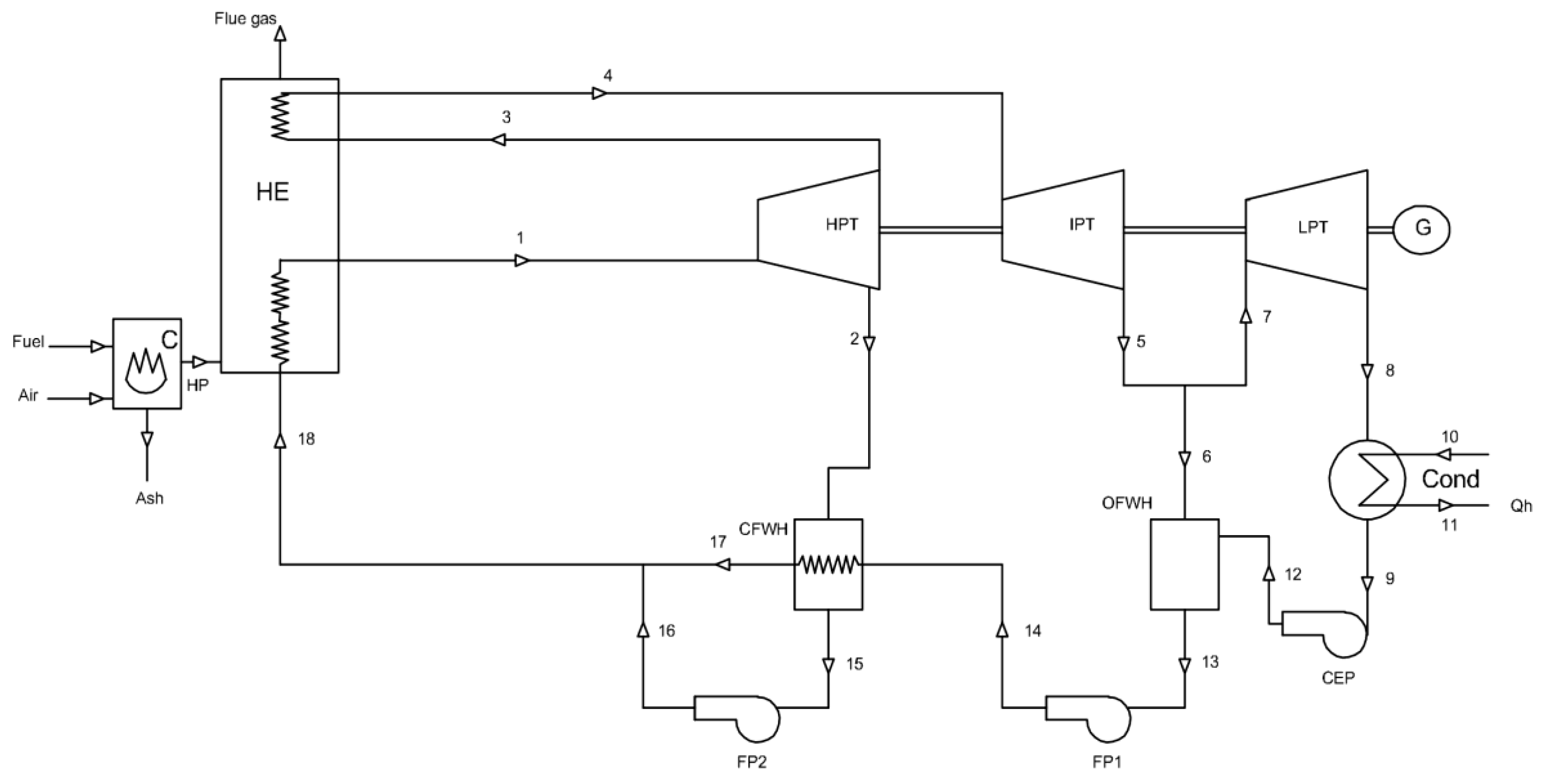
3. Cycle Analysis of a Solid Fuel Fired Power Plant Using the Exergy Method
3.1. Boiler
3.1.1. Boiler Combustor (C)
3.1.2. Boiler Heat Exchanger (HE)
3.2. High Pressure Turbine (HPT)
3.3. Intermediate Pressure Turbine (IPT)
3.4. Low Pressure Turbine (LPT)
3.5. Condenser
3.6. Condensate Extraction Pump (CEP)
3.7. Open Feed Water Heater (OFWH)
3.8. Feed Pump (FP1)
3.9. Closed Feed Water Heater (CFWH)
3.10. Feed Pump (FP2)
4. Application of Exergy Analysis in Solid Fuel-Fired Heat and Power Plants
4.1. Coal-Fired Heat and Power Plants
4.2. Heat and Power Plants Fired by Biomass-Based Fuels
4.3. Biomass and Coal Co-Fired Heat and Power Plant
5. Discussion
6. Conclusions
Acknowledgments
Author Contributions
Conflicts of Interest
Nomenclature
| energy rate (kW) | |
| exergy rate (kW) | |
| ex | specific exergy (kJ/kg) |
| h | specific enthalpy (kJ/kg) |
| irreversibility rate or exergy destruction rate (kW) | |
| mass flow rate (kg/s) | |
| heat transfer rate (kW) | |
| entropy rate (kW/K) | |
| s | specific entropy (kJ/kgK) |
| T | temperature (K) |
| work transfer rate (kW) | |
| Subscripts | |
| a | air |
| f | fuel |
| fg | flue gas |
| hp | hot product |
| L | lost |
| p | product |
| pl | plant |
| e | exit |
| o | out |
| gen | generation |
| i | input |
| 0 | reference environment or dead state |
| Superscripts | |
| Ch | chemical |
| Ke | kinetic energy |
| Pe | potential energy |
| Ph | physical |
| Abbreviations | |
| B | boiler |
| C | combustor |
| CEP | condensate extraction pump |
| CFWH | closed feed water heater |
| CHP | combined heat and power |
| Cond | condenser |
| FP | feed water pump |
| HE | heat exchanger |
| HPT | high pressure turbine |
| IPT | intermediate pressure turbine |
| LPT | low pressure turbine |
| OFWH | open feed water heater |
| HP | hot product |
| WTP | waste-to-energy |
| Greek letter | |
| efficiency |
References
- Gupta, M.K.; Kaushik, S.C.; Ranjan, K.R.; Panwar, N.L.; Reddy, V.S.; Tyagi, S.K. Thermodynamic performance evaluation of solar and other thermal power generation systems: A review. Renew. Sustain. Energy Rev. 2015, 50, 567–582. [Google Scholar] [CrossRef]
- Pazheri, F.R.; Othman, M.F.; Malik, N.H. A review on global renewable electricity scenario. Renew. Sustain. Energy Rev. 2014, 31, 835–845. [Google Scholar] [CrossRef]
- Ranjan, K.R.; Kaushik, S.C. Energy, exergy and thermo-economic analysis of solar distillation systems: A review. Renew. Sustain. Energy Rev. 2013, 27, 709–723. [Google Scholar] [CrossRef]
- Luis, P.; Van der Bruggen, B. Exergy analysis of energy-intensive production processes: Advancing towards a sustainable chemical industry. J. Chem. Technol. Biotechnol. 2014, 89, 1288–1303. [Google Scholar] [CrossRef]
- Hinderink, A.P.; Arons, J.D.; Van der Kooi, H. On the efficiency and sustainability of the process industry. Green Chem. 1999, 1, G176–G180. [Google Scholar] [CrossRef]
- Gallo, W.L.R.; Milanez, L.F. Choice of a reference state for exergetic analysis. Energy 1990, 15, 113–121. [Google Scholar] [CrossRef]
- Ray, T.K.; Datta, A.; Gupta, A.; Ganguly, R. Exergy-based performance analysis for proper O&M decisions in a steam power plant. Energy Convers. Manag. 2010, 51, 1333–1344. [Google Scholar]
- Gaggioli, R.A.; Wepfer, W.J. Exergy economics. Energy 1980, 5, 823–837. [Google Scholar] [CrossRef]
- Luis, P. Exergy as a tool for measuring process intensification in chemical engineering. J. Chem. Technol. Biotechnol. 2013, 88, 1951–1958. [Google Scholar] [CrossRef]
- Rosen, M.A.; Dincer, I. On exergy and environmental impact. Int. J. Energy Res. 1997, 21, 643–654. [Google Scholar] [CrossRef]
- Richards, T.; Pavletic, C.; Pettersson, J. Efficiencies of NaOH production methods in a Kraft pulp mill. Int. J. Energy Res. 2009, 33, 1341–1351. [Google Scholar] [CrossRef]
- Saidur, R.; Ahamed, J.U.; Masjuki, H.H. Energy, exergy and economic analysis of industrial boilers. Energy Policy 2010, 38, 2188–2197. [Google Scholar] [CrossRef]
- Dewulf, J.; Van Langenhove, H.; Muys, B.; Bruers, S.; Bakshi, B.R.; Grubb, G.F.; Paulus, D.M.; Sciubba, E. Exergy: Its potential and limitations in environmental science and technology. Environ. Sci. Technol. 2008, 42, 2221–2232. [Google Scholar] [CrossRef] [PubMed]
- Bejan, A. Fundamentals of exergy analysis, entropy generation minimization, and the generation of flow architecture. Int. J. Energy Res. 2002, 26, 545–565. [Google Scholar] [CrossRef]
- Ni, M.; Leung, D.Y.C.; leung, M.K.H.; Sumathy, K. An overview of hydrogen production from biomass. Fuel Process. Technol. 2006, 87, 461–472. [Google Scholar] [CrossRef]
- Sudheer, P.D.V.N.; David, Y.; Chae, C.G.; Kim, Y.J.; Baylon, M.G.; Baritugo, K.-A.; Kim, T.W.; Kim, M.-S.; Na, J.G.; PARK, S.J. Advances in the biological treatment of coal for synthetic natural gas and chemicals. Korean J. Chem. Eng. 2016, 33, 2788–2801. [Google Scholar] [CrossRef]
- Zhang, L.; Xu, C.; Champagne, P. Overview of recent advances in thermo-chemical conversion of biomass. Energy Convers. Manag. 2010, 51, 969–982. [Google Scholar] [CrossRef]
- Kaushik, S.C.; Reddy, V.S.; Tyagi, S.K. Energy and exergy analyses of thermal power plants: A review. Renew. Sustain. Energy Rev. 2011, 15, 1857–1872. [Google Scholar] [CrossRef]
- Naik, R.J.; Gupta, B.; Sharma, G.S. Exergy analysis of 4.5 MW biomass-based steam power plant. J. Human Soc. Sci. 2012, 1, 1–4. [Google Scholar]
- Demirbas, A. Combustion systems for biomass fuel. Energy Sources A Recovery Util. Environ. Eff. 2007, 29, 303–312. [Google Scholar] [CrossRef]
- Saidur, R.; Boroumandjazi, G.; Mekhilef, S.; Mohammed, H.A. A review on exergy analysis of biomass based fuels. Renew. Sustain. Energy Rev. 2012, 16, 1217–1222. [Google Scholar] [CrossRef]
- Szargut, J.; Morris, D.R.; Steward, F.R. Exergy Analysis of Thermal, Chemical, and Metallurgical Processes; Hemisphere: New York, NY, USA, 1988. [Google Scholar]
- Regulagadda, P.; Dincer, I.; Naterer, G.F. Exergy analysis of a thermal power plant with measured boiler and turbine losses. Appl. Therm. Eng. 2010, 30, 970–976. [Google Scholar] [CrossRef]
- Dincer, I.; Rosena, M.A. Exergy, Environment and Sustainable Development; Elsevier: Oxford, UK, 2007. [Google Scholar]
- Amirabedin, E.; McIlveen-Wright, D. A feasibility study of co-firing biomass in the thermal power plant at Soma in order to reduce emissions: An exergy approach. Int. J. Environ. Res. 2013, 7, 139–154. [Google Scholar]
- Rosen, M.A.; Dincer, I. Effect of varying dead-state properties on energy and exergy analyses of thermal systems. Int. J. Therm. Sci. 2004, 43, 121–133. [Google Scholar] [CrossRef]
- Ganapathy, T.; Alagumurthi, N.; Gakkhar, R.P.; Murugesan, K. Exergy analysis of operating lignite-fired thermal power plant. J. Eng. Sci. Technol. Rev. 2009, 2, 123–130. [Google Scholar]
- Soltani, R.; Dincer, I.; Rosen, M.A. Thermodynamic analysis of a novel multigeneration energy system based on heat recovery from a biomass CHP cycle. Appl. Therm. Eng. 2015, 89, 90–100. [Google Scholar] [CrossRef]
- Rant, Z. Towards the estimation of specific exergy of fuels. Allg. Wärmetech. 1961, 10, 172–176. (In German) [Google Scholar]
- Szargut, J.; Styrylska, T. Approximate evaluation of the exergy of fuels (in German). Brennst. Warme Kraft 1964, 16, 589–596. [Google Scholar]
- Eisermann, W.; Johnson, P.; Conger, W.L. Estimating thermodynamic properties of coal, char, tar and ash. Fuel Process. Technol. 1980, 3, 39–53. [Google Scholar] [CrossRef]
- Shieh, J.H.; Fan, L.T. Estimation of energy (enthalpy) and exergy (availability) contents in structurally complicated materials. Energy Sources 1982, 6, 1–46. [Google Scholar] [CrossRef]
- Ikumi, S.; Luo, C.D.; Wen, C.Y. Method of estimating entropies of coals and coal liquids. Can. J. Chem. Eng. 1982, 60, 551–555. [Google Scholar] [CrossRef]
- Bilgen, S.; Kaygusuz, K. The calculation of the chemical exergies of coal-based fuels by using the higher heating values. Appl. Energy 2008, 85, 776–785. [Google Scholar] [CrossRef]
- Song, G.; Shen, L.; Xiao, J. Estimating specific chemical exergy of biomass from basic analysis data. Ind. Eng. Chem. Res. 2011, 50, 9758–9766. [Google Scholar] [CrossRef]
- Song, G.; Xiao, J.; Zhao, H.; Shen, L. A unified correlation for estimating specific chemical exergy of solid and liquid fuels. Energy 2012, 40, 164–173. [Google Scholar] [CrossRef]
- Eboh, F.C.; Ahlström, P.; Richards, T. Estimating the specific chemical exergy of municipal solid waste. Energy Sci. Eng. 2016, 4, 217–231. [Google Scholar] [CrossRef]
- Tsatsaronis, G.; Park, M.-H. On avoidable and unavoidable exergy destructions and investment costs in thermal systems. Energy Convers. Manag. 2002, 43, 1259–1270. [Google Scholar] [CrossRef]
- Borgnakke, C.; Sonntag, R. Fundamentals of Thermodynamics; John Wiley & Sons, Inc.: Danvers, MA, USA; Chichester, UK, 2008. [Google Scholar]
- Singh, O. Applied Thermodynamics; New Age International (P) Ltd.: New Delhi, India, 2003. [Google Scholar]
- Erdem, H.H.; Dagdas, A.; Sevilgen, S.H.; Cetin, B.; Akkaya, A.V.; Sahin, B.; Teke, I.; Gungor, C.; Atas, S. Thermodynamic analysis of an existing coal-fired power plant for district heating/cooling application. Appl. Therm. Eng. 2010, 30, 181–187. [Google Scholar] [CrossRef]
- Liao, C.; Ertesvåg, I.S.; Zhao, J. Energetic and exergetic efficiencies of coal-fired CHP (combined heat and power) plants used in district heating systems of China. Energy 2013, 57, 671–681. [Google Scholar] [CrossRef]
- Kamate, S.; Gangavati, P. Energy and exergy analysis of a 44-MW bagasse-based cogeneration plant in India. Cogener. Distrib. Gener. J. 2010, 25, 35–51. [Google Scholar] [CrossRef]
- Wang, L.; Yang, Y.; Morosuk, T.; Tsatsaronis, G. Advanced thermodynamic analysis and evaluation of a supercritical power plant. Energies 2012, 5, 1850–1863. [Google Scholar] [CrossRef]
- Coal Industry Advisory Board: IEA Programme of Power Generation from Coal. Measuring and Reporting Efficiency Performance and CO2 Emissions, OECD/IEA. 2010. Available online: https://www.iea.org/ciab/papers/power_generation_from_coal.pdf (accessed on 5 July 2016).
- Fu, C.; Anantharaman, R.; Jordal, K.; Gundersen, T. Thermal efficiency of coal-fired power plants: From theoretical to practical assessments. Energy Convers. Manag. 2015, 105, 530–544. [Google Scholar] [CrossRef]
- Olaleye, A.K.; Wang, M.; Kelsall, G. Steady state simulation and exergy analysis of supercritical coal-fired power plant with CO2 capture. Fuel 2015, 151, 57–72. [Google Scholar] [CrossRef]
- Gürtürk, M.; Oztop, H.F. Exergy analysis of a circulating fluidized bed boiler cogeneration power plant. Energy Convers. Manag. 2016, 120, 346–357. [Google Scholar] [CrossRef]
- Kopac, M.; Hilalci, A. Effect of ambient temperature on the efficiency of the regenerative and Reheat Çatalağzı power plant in Turkey. Appl. Therm. Eng. 2007, 27, 1377–1385. [Google Scholar] [CrossRef]
- Eskin, N.; Gungor, A.; Özdemir, K. Effects of operational parameters on the thermodynamic performance of FBCC steam power plant. Fuel 2009, 88, 54–66. [Google Scholar] [CrossRef]
- Srinivas, T.; Gupta, A.V.S.S.K.S.; Reddy, B.V. Generalized thermodynamic analysis of steam power cycles with ‘n’ number of feedwater heaters. Int. J. Thermodyn. 2007, 10, 177–185. [Google Scholar]
- Sengupta, S.; Datta, A.; Duttagupta, S. Exergy analysis of a coal-based 210 MW thermal power plant. Int. J. Energy Res. 2007, 31, 14–28. [Google Scholar] [CrossRef]
- Pattanayak, L.; Sahu, J.N. Steady state modeling on energy and exergy analysis of a pulverized coal fired thermal power plant. Asia-Pac. J. Chem. Eng. 2015, 10, 876–884. [Google Scholar] [CrossRef]
- Rosen, M.A. Energy and exergy-based comparison of coal-fired and nuclear steam power plants. Int. J. Exergy 2001, 3, 180–192. [Google Scholar] [CrossRef]
- Erdem, H.H.; Akkaya, A.V.; Cetin, B.; Dagdas, A.; Sevilgen, S.H.; Sahin, B.; Teke, I.; Gungor, C.; Atas, S. Comparative energetic and exergetic performance analyses for coal-fired thermal power plants in Turkey. Int. J. Therm. Sci. 2009, 48, 2179–2186. [Google Scholar] [CrossRef]
- Rosen, M.A.; Tang, R. Assessing and improving the efficiencies of a steam power plant using exergy analysis. Part 2: Improvements from modifying reheat pressure. Int. J. Exergy 2006, 4, 377–390. [Google Scholar] [CrossRef]
- Khoodaruth, A.; Aljundi, I.H. Performance analysis of a grate stroker coal-fired power plant based on the second law of thermodynamics. Int. J. Exergy 2015, 1, 84–103. [Google Scholar] [CrossRef]
- Nazrul Islam, A.K.M.; Alam, F.; Ashraful Islam, M. Energy and exergy analysis of a coal-based thermal power plant. In Proceedings of the 6th Bangladesh Society of Mechanical Engineers International Conference on Thermal Engineering, Dhaka, Bangladesh, 19–21 December 2014.
- Ashok, K.T.; Chandramouli, R.; Jothikumar, K. Exergy analysis of a coal based 63 MW circulating fluidized bed boiler—A case study. J. Appl. Sci. 2014, 14, 1515–1521. [Google Scholar]
- Habib, M.A.; Said, S.A.M.; Al-Bagawi, J.J. Thermodynamic performance analysis of the Ghazlan power plant. Energy 1995, 20, 1121–1130. [Google Scholar] [CrossRef]
- Callak, M.; Balkan, F.; Hepbasli, A. Avoidable and unavoidable exergy destructions of a fluidized bed coal combustor and a heat recovery steam generator. Energy Convers. Manag. 2015, 98, 54–58. [Google Scholar] [CrossRef]
- Mahamud, R.; Khan, M.M.K.; Rasul, M.G.; Leinster, M.G. Exergy analysis and efficiency improvement of a coal-fired thermal power in Queensland. In Thermal Power Plants: Advanced Applications; Rasul, M.G., Ed.; lnTech: Rijeka, Croatia, 2013; Chapter 1. [Google Scholar]
- Taniguchi, H.; Mouri, K.; Nakahara, T.; Arai, N. Exergy analysis on combustion and energy conversion processes. Energy 2005, 30, 111–117. [Google Scholar] [CrossRef]
- Oktay, Z. Investigation of coal-fired power plants in Turkey and a case study: Can plant. Appl. Therm. Eng. 2009, 29, 550–557. [Google Scholar] [CrossRef]
- Demirbaş, A. Biomass resource facilities and biomass conversion processing for fuels and chemicals. Energy Convers. Manag. 2001, 42, 1357–1378. [Google Scholar] [CrossRef]
- McKendry, P. Energy production from biomass (Part 1): Overview of biomass. Bioresour. Technol. 2002, 83, 37–46. [Google Scholar] [CrossRef]
- Li, C.; Gillum, C.; Toupin, K.; Donaldson, B. Biomass boiler energy conversion system analysis with the aid of exergy-based methods. Energy Convers. Manag. 2015, 103, 665–673. [Google Scholar] [CrossRef]
- Abbasi, T.; Abbasi, S.A. Biomass energy and the environmental impacts associated with its production and utilization. Renew. Sustain. Energy Rev. 2010, 14, 919–937. [Google Scholar] [CrossRef]
- McKendry, P. Energy production from biomass (Part 2): Conversion technologies. Bioresour. Technol. 2002, 83, 47–54. [Google Scholar] [CrossRef]
- Athari, H.; Soltani, S.; Seyed Mahmoudi, S.M.; Rosen, M.A.; Morosuk, T. Exergoeconomic analysis of a biomass post-firing combined-cycle power plant. Energy 2014, 77, 553–561. [Google Scholar] [CrossRef]
- Kamate, S.C.; Gangavati, P.B. Exergy analysis of cogeneration power plants in sugar industries. Appl. Therm. Eng. 2009, 29, 1187–1194. [Google Scholar] [CrossRef]
- Baloyi, J.; Bello-Ochende, T.; Meyer, J.P. Thermodynamic optimisation and computational analysis of irreversibilities in a small-scale wood-fired circulating fluidised bed adiabatic combustor. Energy 2014, 70, 653–663. [Google Scholar] [CrossRef]
- Solheimslid, T.; Harneshaug, H.K.; Lümmen, N. Calculation of first-law and second-law-efficiency of a Norwegian combined heat and power facility driven by municipal waste incineration—A case study. Energy Convers. Manag. 2015, 95, 149–159. [Google Scholar] [CrossRef]
- Grosso, M.; Motta, A.; Rigamonti, L. Efficiency of energy recovery from waste incineration, in the light of the new waste framework directive. Waste Manag. 2010, 30, 1238–1243. [Google Scholar] [CrossRef] [PubMed]
- Tillman, D.A. Biomass co-firing: The technology, the experience, the combustion consequences. Biomass Bioenergy 2000, 19, 365–384. [Google Scholar] [CrossRef]
- Khorshidi, Z.; Ho, M.T.; Wiley, D.E. Techno-economic study of biomass co-firing with and without CO2 capture in an Australian black coal-fired power plant. Energy Procedia 2013, 37, 6035–6042. [Google Scholar] [CrossRef]
- Nussbaumer, T. Combustion and co-combustion of biomass: Fundamentals, technologies, and primary measures for emission reduction. Energy Fuels 2003, 17, 1510–1521. [Google Scholar] [CrossRef]
- Basu, P.; Butler, J.; Leon, M.A. Biomass co-firing options on the emission reduction and electricity generation costs in coal-fired power plants. Renew. Energy 2011, 36, 282–288. [Google Scholar] [CrossRef]
- Obernberger, I.; Thek, I. The Pellet Handbook; Earthscan: London, UK, 2010. [Google Scholar]
- Baxter, L.; Koppejan, J. Biomass-Coal Co-Combustion: Opportunity for Affordable Renewable Energy. 2004. Available online: http://www.ieabcc.nl/publications/paper_cofiring.pdf (accessed on 1 July 2016).
- The European Bioenergy Networks (EUBIONET): Biomass Co-Firing- an Efficient Way to Reduce Greenhouse Gas Emissions. 2003. Available online: https://ec.europa.eu/energy/sites/ener/files/documents/2003_cofiring_eu_bionet.pdf (accessed on 8 July 2003).
- Al-Mansour, F.; Zuwala, J. An evaluation of biomass co-firing in Europe. Biomass Bioenergy 2010, 34, 620–629. [Google Scholar] [CrossRef]
- Mehmood, S.; Reddy, B.V.; Rosen, M.A. Exergy analysis of a biomass co-firing based pulverized coal power generation system. Int. J. Green Energy 2015, 12, 461–478. [Google Scholar] [CrossRef]
- Martín, C.; Villamañán, M.A.; Chamorro, C.R.; Otero, J.; Cabanillas, A.; Segovia, J.J. Low-grade coal and biomass co-combustion on fluidized bed: Exergy analysis. Energy 2006, 31, 330–344. [Google Scholar] [CrossRef]
- De, S.; Assadi, M. Impact of cofiring biomass with coal in power plants—A techno-economic assessment. Biomass Bioenergy 2009, 33, 283–293. [Google Scholar] [CrossRef]
- Wang, M.; Lawal, A.; Stephenson, P.; Sidders, J.; Ramshaw, C. Post-combustion CO2 capture with chemical absorption: A state-of-the-art review. Chem. Eng. Res. Des. 2011, 89, 1609–1624. [Google Scholar] [CrossRef] [Green Version]
- Kaygusuz, K.; Türker, M.F. Biomass energy potential in Turkey. Renew. Energy 2002, 26, 661–678. [Google Scholar] [CrossRef]
- Zeng, X.; Ma, Y.; Ma, L. Utilization of straw in biomass energy in China. Renew. Sustain. Energy Rev. 2007, 11, 976–987. [Google Scholar] [CrossRef]
- Li, C.; Liu, D.; Ramaswamy, S.; Yan, J. Biomass energy and products: Advanced technologies and applications. Appl. Energy 2015, 157, 489–490. [Google Scholar] [CrossRef]
- Wang, J.-J.; Yang, K.; Xu, Z.-L.; Fu, C. Energy and exergy analyses of an integrated CCHP system with biomass air gasification. Appl. Energy 2015, 142, 317–327. [Google Scholar] [CrossRef]
- Gungor, A. Simulation of co-firing coal and biomass in circulating fluidized beds. Energy Convers. Manag. 2013, 65, 574–579. [Google Scholar] [CrossRef]
- Tsatsaronis, G.; Morosuk, T.; Koch, D.; Sorgenfrei, M. Understanding the thermodynamic inefficiencies in combustion processes. Energy 2013, 62, 3–11. [Google Scholar] [CrossRef]


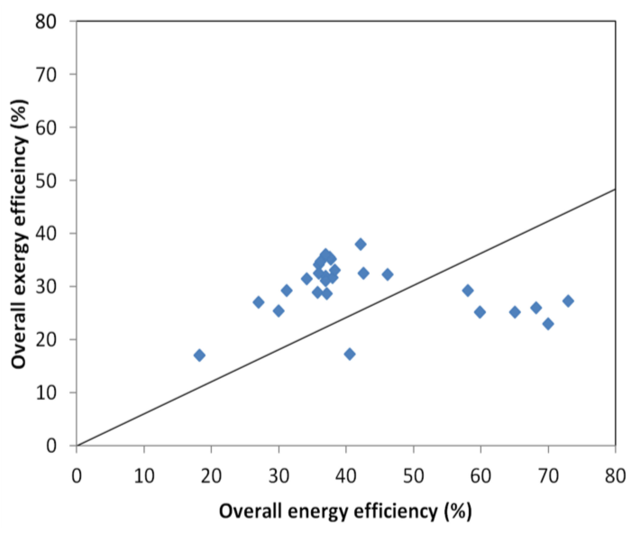
| Plant Capacity (MW) | Combustion Technology | Plant Output Generation | Country | Exergy (%) | Energy Efficiency (%) | Aims | Major Results | Ref. |
|---|---|---|---|---|---|---|---|---|
| 32 | Conventional | Electricity | India | 25.38 | 30.12 | To conduct a thermodynamics analysis, using the design data of a coal–fired power plant under construction, to identify potential areas for making improvements to performance. To investigate the effects of varying the operating parameters on performance. | The largest losses occurred in the condenser when energy analysis was used. When exergy analysis was applied, however, the actual major losses were found in the boiler, which has the highest exergy destruction. This is due to heat being transferred to the working fluid, the combustion reaction and losses caused by emissions of flue gases. Increasing the steam pressure and temperature, and reducing the pressure in the steam condenser, increased the energy and exergy efficiencies of the plant. | [23] |
| 500 | Conventional | Electricity | Canada | 36 | 37 | To examine sensitivity to reasonable variations in dead-state properties of several energy and exergy values. To examine the results of energy and exergy analyses of a complex device. | The energy and exergy values were not significantly sensitive to reasonable variations in dead-state properties; the main results of energy and exergy analyses were not, generally speaking, significantly sensitive to variations in these properties. Variations in the reference temperature considered, , did not affect the overall results of the energy and exergy efficiencies of the plant significantly. | [26] |
| 50 | Conventional | Electricity | India | 26.95 | 27 | To conduct an exergy analysis on the power generation of Unit V, Thermal Power Station 1 of Neyveli Lignite Corp. Ltd. (Tamil Nadu, India) in order to discover the exergy losses in various components of the plant. | The maximum energy loss (39%) occurred in the condenser while the total plant exergy destruction was calculated as being 73%. The maximum exergy loss (57.35%) occurred in the boiler, with 42.73% losses being located in the combustion. | [27] |
| 1.5 | Fluidized bed | Cogeneration | Turkey | 20 | - | To perform an exergy analysis of a cogeneration power plant, located in Çankırı, that generates electricity and steam used for producing salt. | The highest exergy destruction rate took place in the boiler, which had 85.89% of the total exergy loss in the system. Improvements to the design parameters (e.g., pressure, fluidized velocity, particle size and geometry) as well as feeding the coal from different points into the boiler should affect the combustion and overall plant efficiencies positively. | [48] |
| 150 | Conventional | Electricity | Turkey | 35.19 | 37.88 | To determine the effect of the ambient temperature on the irreversible losses and efficiency in the Catalgzi Power Plant in Zonguldak. | The irreversibility rates of the boiler were larger than for other components and increased slightly, together with total irreversibility rate, as the ambient temperature was increased from 278 to 308 K, while that of the condenser decreased with increasing ambient temperature. The boiler was the major source of exergy consumption (a result of the chemical reaction between fuel and air) and therefore has the largest potential for improvement. | [49] |
| 7.7 | Fluidized bed | Cogeneration | Turkey | 23 | 70 | To analyse the thermodynamics of a coal-fired fluidized bed power plant to show the effects that excess air, steam pressure and type of coal have on the first and second laws of efficiency in the thermal power plant. | Second law analysis revealed that the FBCC had the largest irreversibility, about 80.4% of the system’s total exergy loss. The chemical reaction (72%), heat transfer processes (20%) and physical transport (8%) are the sources of irreversibilities in the combustion process in FBCC. The system’s exergy efficiency increased with steam pressure, while types of coal did not affect the second law efficiency. As the excess air value increased, the exergy and energy efficiencies decreased, due to heat losses being higher when the flow rates of the flue gas increased and combustion temperature decreased: these affect the reaction rate of the fuel negatively. | [50] |
| - | Conventional | Electricity | - | 34 | 36 | To investigate the effects of feed water heaters on the performance of a coal-fired power plant using thermodynamic analysis. | For a single feed water heater, efficiency was maximized at a bled steam temperature ratio of 0.4. The efficiency of the cycle was high when the reheater pressure was 20%–25% of the boiler pressure. The exergetic loss in the boiler decreased with the addition of feed water heaters. | [51] |
| 210 | Conventional | Electricity | India | 34.50 | 36.20 | To apply exergy analysis to a coal-based thermal power plant at different operating loads, condenser pressures, with/without certain feed water heaters, and for different governor settings of the turbine valves, i.e., constant pressure operation or sliding pressure operation. | Reducing the plant load and increasing the throttle of control valves increased the irreversibilities in the cycle, whilst increasing the condenser’s back pressure decreased the exergy efficiency. Withdrawal at the high pressure heaters showed a decrease in the exergy efficiency of the entire plant. The exergy efficiency of a part load operation improved when the main stream pressure prior to the turbine valves was kept in sliding mode. | [52] |
| 500 | Conventional | Electricity | India | 31.47 | 34.33 | To analyse a pulverized coal-fired power plant in a steady-state condition using energy and exergy analyses. | With the plant operating at a capacity of 460 MW, there was a reduction of approx. 8.69% and 9.10%, respectively, in the energy and exergy efficiencies compared to the ratings for the load range designed. | [53] |
| 500 | Conventional | Electricity | Canada | 36 | 37 | To compare coal and nuclear electric generating stations thermodynamically, using energy and exergy analysis. | In the coal-fired plant, 67% and 33% of the exergy consumed was due to combustion and heat transfer respectively, In the nuclear power plant, 5%, 0.9%, 0.1% and 94% of the exergy destroyed was due to the boiler, moderator cooler, heavy-water pump and reactor, respectively. | [54] |
| 3 × 210 | Conventional | Electricity | Turkey | 31.95 | 37.01 | To make a comparative analysis of the performance of nine coal thermal power plants from energetic and exergetic aspects. | The plant with a capacity of 320 MW had the highest exergetic performance: the exergy efficiency of a boiler with a circulating bed combustor had the highest value of all plant boilers. Boilers are vital components because they have the highest exergy losses in a plant: they should therefore be investigated so that the overall exergetic performance may be enhanced. | [55] |
| 4 × 150 | Conventional | Electricity | Turkey | 31.50 | 38.03 | |||
| 2 × 150 | Conventional | Electricity | Turkey | 35.19 | 37.88 | |||
| 3 × 157 | Conventional | Electricity | Turkey | 28.55 | 37.19 | |||
| 4 × 360 | Conventional | Electricity | Turkey | 32.46 | 42.64 | |||
| 210 | Conventional | Electricity | Turkey | 35.49 | 37.63 | |||
| 6 × 165 | Conventional | Electricity | Turkey | 32.35 | 36.08 | |||
| 5 × 160.9 | Conventional | Electricity | Turkey | 33.09 | 38.44 | |||
| 2 × 160 | Circulating fluidized bed | Electricity | Turkey | 37.88 | 42.12 | |||
| 3 × 210 | Conventional | Electricity | Turkey | 31.95 | 37.01 | To determine the most convenient point of extraction of energy for use in district heating/cooling in the conventional coal-fired Yatagan Thermal Power Plant, using thermodynamic analysis to examine the energetic and exergetic performances. | The most convenient point for extracting steam in the plant analysed was found to be the low-pressure turbine inlet stage. | [41] |
| 500 | Conventional | Electricity | Canada | 36 | 37 | To examine the effect of increasing the reheat pressure on the irreversibility rate and exergy efficiency in a coal-fired steam power plant. | The irreversibility rate associated with heat transfer in the steam generator decreased as the reheat pressure increased. However, the overall-plant exergy efficiency decreased due to the large decrease in the power output of the shaft. The decrease in the plant’s thermal and exergy efficiencies over the range of reheat pressures considered was nearly 9.3%. | [56] |
| 32.5 | Conventional | Electricity | India | 17.8 | - | To analyse the performance of a coal-fired stoker power plant using exergy analysis. To investigate the effects of varying the operating temperatures of the boiler as well as the reference temperature state. | The boiler had the highest exergy destruction rate, with 77% of the total exergy loss being due to flue gas emissions, flue gas temperature, combustion reactions and heat transfer to the steam. The efficiency of the power plant increased from 18% to 42% when the temperature of the exiting steam increased from 723 K to 793 K. Varying the reference state temperature had no significant impact on the plant’s overall performance. | [57] |
| 250 | Conventional | Electricity | Bangladesh | 30.78 | - | To investigate a coal-based thermal plant operating at sub-critical steam conditions using thermodynamic performance criteria. | The maximum exergy losses occurred in the boiler: the large exergy loss was mainly due to the combustion reaction and the high temperature difference between the combustion gas and the steam. | [58] |
| 63 | Circulating fluidized bed | Electricity | India | 29.29 | 31.15 | To establish the energy and exergy flows of each component in the coal-based circulating fluidized bed boiler in the Tuticorin Power Plant in order to identify the major area of exergy loss. | 74% of the total exergy loss occurred in the furnace of the boiler system; 54.1% of the loss was located in the furnace’s combustion chamber. | [59] |
| 4 × 400 | Conventional | Electricity | Saudi Arabia | 35.77 | - | To evaluate the design and performance of the existing Ghazlan Power Plant using the exergy concept. | The major energy losses were due to heat rejection in the condenser and stack gases, while the highest exergy losses of 70.6% of the total loss occurred in the boiler. | [60] |
| 7.7 | Fluidized bed | Cogeneration | Turkey | 23 | 70 | To apply conventional and advanced exergy analysis to a fluidized bed coal combustion (FBCC) and heat recovery steam generator (HRSG) in a textile plant. | A total exergy destruction of 5104 kW occurred in the system, the major part of which (4285 kW) was in the FBCC. The conventional exergy efficiencies in the FBCC and HRSG were 44.2% and 46.2%, respectively, and 53.1% and 48.1%, respectively, for advanced exergy efficiencies. | [61] |
| 145 200 300 | Conventional | Cogeneration | China | 29.1 32.2 27.3 | 58.2 46.2 73 | To investigate the most important operating parameters affecting the energetic and exergetic efficiencies, and their influence on the performance of three different coal-fired combined power (CHP) plants under various operational conditions in the district heating (DH) system. | The extraction flow rate and extraction pressure were the most important parameters of the energetic and exergetic efficiencies, respectively, in the three power plants. When the extraction ratio increased, the energetic efficiency increased, whereas the exergetic efficiency decreased. A high extraction ratio and a low extraction pressure gave the best performance in the CHP. A higher extraction pressure led to a higher heat delivery. | [42] |
| 280 | Conventional | Electricity | Australia | - | - | To conduct an exergy analysis of a coal-fired power plant in central Queensland. | The highest exergy destruction occurred in the boiler, which had 81% of the total exergy destruction in the plant. This differs to the energy balance, which showed that most of the energy loss occurred in the condenser, where 69% of the total was lost. The exergy loss in the boiler was a result of (i) its internal loss, (ii) the loss in its blowdown stream and (iii) the heat loss caused by the stream of flue gas: the greatest exergy loss occurred in the boiler´s internal heat transfer arrangement. A steam boiler has a great potential for improving the overall efficiency of a plant. | [62] |
| Components | Exergy Destruction (kW) | Heat Loss (kW) | Entropy Generation (kW/K) |
|---|---|---|---|
| Boiler | 73,046 | 12,663 | 3312.0 |
| Turbine | 6403 | 3242 | 17.2 |
| ACC (air cooled condenser) | 1622 | 33 | 3.3 |
| Deaerator | 886 | 71 | 1.4 |
| LP heater | 552 | 336 | 2.4 |
| HP heater | 759 | 65 | 2.7 |
| Boiler feed pump | 375 | 140 | 0.0 |
| Generator | 550 | 656 | 0.9 |
| Total | 84,193 | 50,456 | 3339.9 |
| Temperature (K) | Exergy Efficiency (%) | Energy Efficiency (%) |
|---|---|---|
| 273 | 25.3970 | 30.12 |
| 283 | 25.3920 | 30.12 |
| 293 | 25.3884 | 30.12 |
| 303 | 25.3850 | 30.12 |
| 313 | 25.3806 | 30.12 |
| 323 | 25.3760 | 30.12 |
| Reference Temperature | 278 K | 283 K | 288 K | 293 K | 298 K | 303 K | 308 K |
|---|---|---|---|---|---|---|---|
| Fuel exergy rate | 473,500 | 473,500 | 473,500 | 473,500 | 473,500 | 473,500 | 473,500 |
| Irreversibility rate of boiler | 262,520 | 262,561 | 268,602 | 271,643 | 274,684 | 277,725 | 280,766 |
| Irreversibility rate of turbine | 35,594 | 35,941 | 36,288 | 36,636 | 36,983 | 37,330 | 37,678 |
| Irreversibility rate of condenser | 9330 | 7982 | 6871 | 4607 | 2186 | 960 | 373 |
| Irreversibility rate of feed water heaters | 5256 | 5314 | 5371 | 5428 | 5486 | 5543 | 5601 |
| Irreversibility rate of pumps | 1014 | 1028 | 1042 | 1056 | 1070 | 1084 | 1098 |
| Irreversibility rate of pipe | 1418 | 1393 | 1367 | 1342 | 1317 | 1291 | 1266 |
| Total Irreversibility rate | 315,132 | 317,218 | 319,542 | 320,711 | 321,725 | 323,934 | 326,780 |
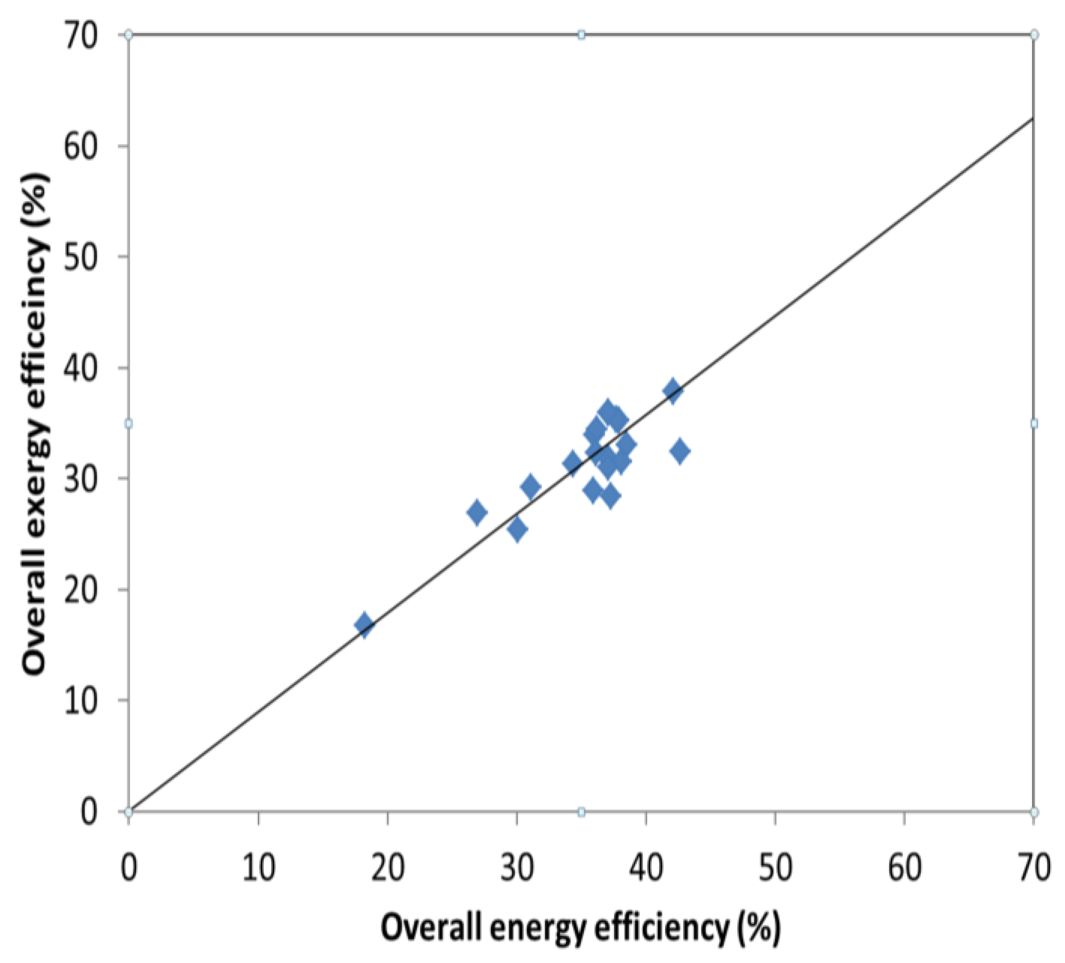
| Plant Capacity (MW) | Combustion Technology | Plant Output Generation | Country | Exergy Efficiency (%) | Energy Efficiency (%) | Aims | Major Results | Ref. |
|---|---|---|---|---|---|---|---|---|
| - | Conventional | Multi-generation | - | 25 | 60 | To model and evaluate a (sawdust) biomass-fired multi-generation energy system using energy and exergy analysis. | The biomass combustor was the location of the main exergy destruction in the system due to irreversible chemical reactions (combustion) and heat transfer across temperature differences between the input and output streams in the heat exchanger. The biomass input rate has a significant effect on the heat available for district heating and electricity generation: whilst it increased the exergy efficiency of the overall multi-generation system, it decreased the energy efficiency slightly. | [28] |
| - | Conventional | - | - | - | - | To establish a theoretical framework for the exergy analysis and advanced exergy analysis of a biomass boiler. | The combustion process dominated the exergy destruction in the main components of a biomass boiler in conventional and advanced exergy analysis. The increase in biomass moisture reduced the adiabatic flame temperature, decreased the total boiler exergy efficiency and decreased the air-fuel ratio. | [67] |
| 4.5 | Conventional | Electricity | India | 16.89 | 18.25 | To conduct an exergy analysis of a biomass-based steam plant in Karempudi. | The boiler had the highest exergy destruction, 49.17% of the total amount, due to irreversibility associated with chemical reactions. | [19] |
| - | Conventional | Cogeneration | India | *30.7 **26.0 *BPST **ECST | *86.3 **68.2 *BPST **ECST | To evaluate, and make an overall assessment of, a bagasse-based cogeneration plant in the sugar industry using back pressure and an extraction condensing stream turbine with a capacity of 2500 tonnes of sugar cane per day. | The back-pressure steam turbine (BPST) was the most effective configuration from an overall perspective but the extraction condensing steam plant (ECST) can produce more power. The boiler was the least efficient component and was the site of the major part of the exergy destruction, but increasing both the steam inlet pressure and temperature decreased irreversibility in the plant’s components. | [71] |
| - | Fluidized bed | - | - | - | - | To analyse the irreversibilities generated during the combustion of wood in an adiabatic combustor. | The rate of entropy generation was entirely due to the combustion process; the irreversibilities generated reached a minimum at an air-fuel mass ratio of 4.9 in an adiabatic combustor. | [72] |
| 44 | Conventional | Cogeneration | India | 25 | 65 | To evaluate bagasse-based cogeneration of power based on a sugar factory in Belgaum with a capacity of 10,000 tons of sugar cane per day (TCD) using energy and exergy analysis. | The major exergy destruction was found in the boiler, where 71% of the fuel exergy input was destroyed. Energy losses occurred mainly in the boiler exhaust and condenser, where 35 MW and 27 MW were lost to the environment, respectively. The plant’s fuel energy savings ratio for the co-generation plant is 8.2% over separate generation. | [43] |
| - | Conventional | Cogeneration | Norway | 17.3 | 40.6 | To calculate the second law efficiency of a municipal solid waste combined heat and power plant located in Bergen using different methods to determine the chemical exergy of the fuel. | The different methods used show comparable results. The second law efficiency was 17.3% for the local surrounding temperature, the energy utilization was 40.6% and the R1 efficiency was 0.568. Focusing on the production of electricity from waste can give larger increases in exergy recovery and exergy efficiency than increasing the delivery of district or process heat. | [73] |
| - | - | - | - | - | - | To analyse critically, and calculate correctly, the efficiency of energy recovered from waste incineration in the new waste framework directive. To compare the energy recovery efficiency to the more scientifically-based approach of exergy efficiency. | The average energy recovery efficiencies calculated for CHP plants, plants producing mainly electricity and plants only producing heat were 0.71,0.49 and 0.64, respectively, whilst the average exergy efficiencies for these plants were 20.9%,19.4% and 18.8%, respectively. The average energy recovery efficiency of WTE plants is higher in northern Europe than in southern, as a result of the cogeneration technology that is mostly used there. The energy recovery efficiency in a WTE plant does not take into account the effect of the plant’s size and the influence of climate conditions. The exergy efficiency is a reliable measure of the calculation of efficiency of energy recovery from waste incineration. | [74] |
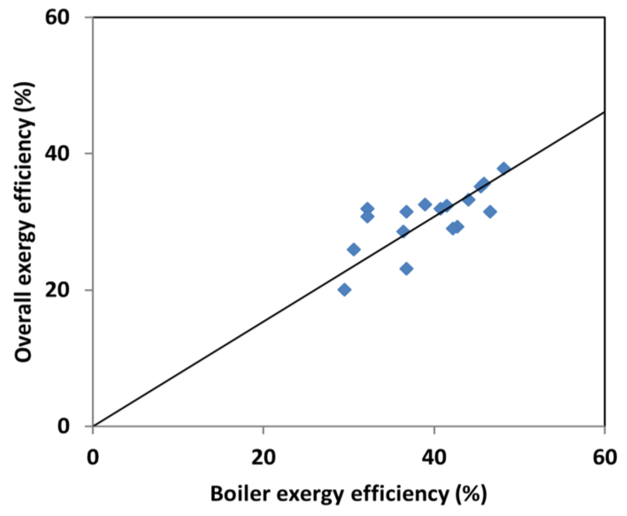
| Plant Capacity (MW) | Combustion Technology | Plant Output Generation | Country | Exergy Efficiency (%) | Energy Efficiency (%) | Aims | Major Results | Ref. |
|---|---|---|---|---|---|---|---|---|
| 165 | Conventional | Electricity | Turkey | 29.04 | 35.91 | To investigate the technical and environmental feasibility of direct and parallel co-firing of biomass * with Soma Lignite Corp. Ltd. in the Soma Thermal Power Plant, using exergy analysis. * corn cobs, cotton gin and olive pits. | Both the direct and parallel co-firing of biomass decreased the consumption rate of lignite and reduced the plant’s emissions of CO2, SO2 and dust significantly. The largest exergy destruction occurred in the boiler. Parallel co-firing offered better technical and environmental performances than direct co-firing. | [25] |
| - | Conventional | Electricity | - | 32.26 | - | To conduct an exergy analysis of a biomass * co-fired based conventional pulverized coal (bituminous and lignite) power plant. * chicken litter, pine sawdust, refuse-derived fuel and rice husks. | The largest exergy destruction occurred in the boiler, due to chemical reactions and heat transfer across a large temperature difference between the product gas and the feed water, with the combustor having the highest degree of destruction. The irreversibility rates of the plant decreased as the content of biomass in the fuel blend increased. However, the exergy efficiencies of the boiler and the overall plant decreased as the co-firing increased. Although biomass co-firing is not advantageous from a thermodynamic perspective, it helps reduce environmental emissions and enhances the finances of the plant. | [83] |
| 1.0 | Fluidized bed | Electricity | - | 32.9 | - | To apply the exergy method to the nine experimental results obtained from the pilot plant, modelled on bubbling fluidized bed co-combustion, using biomass * and low grade Spanish coal. * pine chips, i.e., wood waste. | The exergy destroyed ranged from 48.4% to 56.2% of the exergy input, with highest irreversibility found in the combustion process. The performance of the plant may be improved by reducing the exit temperature of the flue gas by the addition of a heat exchanger; heat loss to the environment can be reduced by insulating the combustion chamber. | [84] |
© 2017 by the authors. Licensee MDPI, Basel, Switzerland. This article is an open access article distributed under the terms and conditions of the Creative Commons Attribution (CC BY) license ( http://creativecommons.org/licenses/by/4.0/).
Share and Cite
Eboh, F.C.; Ahlström, P.; Richards, T. Exergy Analysis of Solid Fuel-Fired Heat and Power Plants: A Review. Energies 2017, 10, 165. https://doi.org/10.3390/en10020165
Eboh FC, Ahlström P, Richards T. Exergy Analysis of Solid Fuel-Fired Heat and Power Plants: A Review. Energies. 2017; 10(2):165. https://doi.org/10.3390/en10020165
Chicago/Turabian StyleEboh, Francis Chinweuba, Peter Ahlström, and Tobias Richards. 2017. "Exergy Analysis of Solid Fuel-Fired Heat and Power Plants: A Review" Energies 10, no. 2: 165. https://doi.org/10.3390/en10020165