Charging Characteristics of Lithium Ion Battery Using Semi-Solar Modules of Polymer:Fullerene Solar Cells


Abstract
:1. Introduction
2. Results
3. Materials and Methods
4. Conclusions
Acknowledgments
Author Contributions
Conflicts of Interest
References
- Krebs, F.C. Fabrication and processing of polymer solar cells: A review of printing and coating techniques. Sol. Energy Mater. Sol. Cells 2009, 93, 394–412. [Google Scholar] [CrossRef]
- Hau, S.K.; Yip, H.-L.; Jen, A.K.-Y. A review on the development of the inverted polymer solar cell architecture. Polym. Rev. 2010, 50, 474–510. [Google Scholar] [CrossRef]
- Lee, S.; Nam, S.; Seo, J.; Jeong, J.; Kim, H.; Woo, S.; Kim, Y. Polymer solar cells with micrometer-scale engraved active nanolayers fabricated by pressing with metal molds. Energy Technol. 2014, 2, 713–720. [Google Scholar] [CrossRef]
- Helgesen, M.; Søndergaard, R.; Krebs, F.C. Advanced materials and processes for polymer solar cell devices. J. Mater. Chem. 2010, 20, 36–60. [Google Scholar] [CrossRef]
- Li, G.; Zhu, R.; Yang, Y. Polymer solar cells. Nat. Photonics 2012, 6, 153–161. [Google Scholar] [CrossRef]
- Sathiyan, G.; Sivakumar, E.K.T.; Ganesamoorthy, R.; Thangamuthu, R.; Sakthivel, P. Review of carbazole based conjugated molecules for highly efficient organic solar cell application. Tetrahedron Lett. 2016, 57, 243–252. [Google Scholar] [CrossRef]
- Kim, H.; Nam, S.; Jeong, J.; Lee, S.; Seo, J.; Han, H.; Kim, Y. Organic solar cells based on conjugated polymers: History and recent advances. Korean J. Chem. Eng. 2014, 31, 1095–1104. [Google Scholar] [CrossRef]
- Krebs, F.C.; Gevorgyan, S.A.; Alstrup, J. A roll-to-roll process to flexible polymer solar cells: Model studies, manufacture and operational stability studies. J. Mater. Chem. 2009, 19, 5442–5451. [Google Scholar] [CrossRef]
- Krebs, F.C.; Tromholt, T.; Jørgensen, M. Upscaling of polymer solar cell fabrication using full roll-to-roll processing. Nanoscale 2010, 2, 873–886. [Google Scholar] [CrossRef] [PubMed]
- Yu, G.; Gao, J.; Hummelen, J.C.; Wudl, F.; Heeger, A.J. Polymer photovoltaic cells: Enhanced efficiencies via a network of internal donor-acceptor heterojunctions. Science 1995, 270, 1789–1791. [Google Scholar] [CrossRef]
- Halls, J.J.M.; Walsh, C.A.; Greenham, N.C.; Marseglia, E.A.; Friend, R.H.; Moratti, S.C.; Holmes, A.B. Efficient photodiodes from interpenetrating polymer networks. Nature 1995, 376, 498–500. [Google Scholar] [CrossRef]
- Shaheen, S.E.; Brabec, C.J.; Sariciftci, N.S. 2.5% efficient organic plastic solar cells. Appl. Phys. Lett. 2001, 78, 841–843. [Google Scholar] [CrossRef]
- Padinger, F.; Rittberger, R.S.; Sariciftci, N.S. Effects of postproduction treatment on plastic solar cells. Adv. Funct. Mater. 2003, 13, 85–88. [Google Scholar] [CrossRef]
- Kim, Y.; Choulis, S.A.; Nelson, J.; Bradley, D.D.C.; Cook, S.; Durrant, J.R. Composition and annealing effects in polythiophene/fullerene solar cells. J. Mater. Sci. 2005, 40, 1371–1376. [Google Scholar] [CrossRef]
- Chu, C.-W.; Li, S.-H.; Chen, C.-W.; Shrotriya, V.; Yang, Y. High-performance organic thin-film transistors with metal oxide/metal bilayer electrode. Appl. Phys. Lett. 2005, 87, 193508. [Google Scholar] [CrossRef]
- Kim, Y.; Choulis, S.A.; Nelson, J.; Bradley, D.D.C. Device annealing effect in organic solar cells with blends of regioregular poly(3-hexylthiophene) and soluble fullerene. Appl. Phys. Lett. 2005, 86, 063502. [Google Scholar] [CrossRef]
- Li, G.; Shrotriya, V.; Huang, J.; Yao, Y.; Moriarty, T.; Emery, K.; Yang, Y. High-efficiency solution processable polymer photovoltaic cells by self-organization of polymer blends. Nat. Mater. 2005, 4, 864–868. [Google Scholar] [CrossRef]
- Reyes-Reyes, M.; Kim, K.; Carroll, D.L. High-efficiency photovoltaic devices based on annealed poly(3-hexylthiophene) and 1-(3-hexylthiophene) and 1-(3-methoxycarbonyl)-propyl-1-phenyl-(6,6)C61 blends. Appl. Phys. Lett. 2005, 87, 083506. [Google Scholar] [CrossRef]
- Kim, Y.; Cook, S.; Tuladhar, S.M.; Choulis, S.A.; Nelson, J.; Durrant, J.R.; Bradley, D.D.C.; Giles, M.; McCulloch, I.; Ha, C.-S.; et al. A strong regioregularity effect in self-organizing conjugated polymer films and high-efficiency polythiophene:fullerene solar cells. Nat. Mater. 2006, 5, 197–203. [Google Scholar] [CrossRef]
- Park, S.; Nam, S.; Seo, J.; Jeong, J.; Lee, S.; Kim, H.; Kim, Y. Effect of halogen-terminated additives on the performance and the nanostructure of all-polymer solar cells. J. Korean Phys. Soc. 2015, 66, 521–525. [Google Scholar] [CrossRef]
- Snaith, H.J.; Arias, A.C.; Morteani, A.C.; Silva, C.; Friend, R.H. Charge generation kinetics and transport mechanisms in blended polyfluorene photovoltaic devices. Nano Lett. 2002, 2, 1353–1357. [Google Scholar] [CrossRef]
- Kim, Y.; Cook, S.; Choulis, S.A.; Nelson, J.; Durrant, J.R.; Bradley, D.D.C. Organic photovoltaic devices based on blends of regioregular poly(3-hexylthiophene) and poly(9,9-dioctylfluorene-co-benzothiadiazole). Chem. Mater. 2004, 16, 4812–4818. [Google Scholar] [CrossRef]
- Nam, S.; Woo, S.; Seo, J.; Kim, W.H.; Kim, H.; McNeill, C.R.; Shin, T.J.; Bradley, D.D.C.; Kim, Y. Pronounced cosolvent effects in polymer:polymer bulk heterojunction solar cells with sulfur-rich electron-donating and imide-containing electron-accepting polymers. ACS Appl. Mater. Interfaces 2015, 7, 15995–16002. [Google Scholar] [CrossRef] [PubMed]
- Zhou, E.; Cong, J.; Wei, Q.; Tajima, K.; Yang, C.; Hashimoto, K. All-polymer solar cells from perylene diimide based copolymers: Material design and phase separation control. Angew. Chem. Int. Ed. 2011, 50, 2799–2803. [Google Scholar] [CrossRef] [PubMed]
- Li, S.; Ye, L.; Zhao, W.; Zhang, S.; Ade, H.; Hou, J. Significant influence of the methoxyl substitution position on optoelectronic properties and molecular packing of small-molecule electron acceptors for photovoltaic cells. Adv. Energy Mater. 2017, 7, 1602000. [Google Scholar] [CrossRef]
- Ye, L.; Xiong, Y.; Yao, H.; Gadisa, A.; Zhang, H.; Li, S.; Ghasemi, M.; Balar, N.; Hunt, A.; O’Connor, B.T.; et al. High performance organic solar cells processed by blade coating in air from a benign food additive solution. Chem. Mater. 2016, 28, 7451–7458. [Google Scholar] [CrossRef]
- Ye, L.; Xiong, Y.; Li, S.; Ghasemi, M.; Balar, N.; Turner, J.; Gadisa, A.; Hou, J.; O’Connor, B.T.; Ade, H. Precise manipulation of multilength scale morphology and its influence on eco-friendly printed all-polymer solar cells. Adv. Funct. Mater. 2017, 27, 1702016. [Google Scholar] [CrossRef]
- Nam, S.; Hahm, S.G.; Han, H.; Seo, J.; Kim, C.; Kim, H.; Marder, S.R.; Ree, M.; Kim, Y. All-polymer solar cells with bulk heterojunction films containing electron-accepting triple bond-conjugated perylene diimide polymer. ACS Sustain. Chem. Eng. 2016, 4, 767–774. [Google Scholar] [CrossRef]
- Fan, B.; Ying, L.; Wang, Z.; He, B.; Jiang, X.-F.; Huang, F.; Cao, Y. Optimisation of processing solvent and molecular weight for the production of green-solvent-processed all-polymer solar cells with a power conversion efficiency over 9%. Energy Environ. Sci. 2017, 10, 1243–1251. [Google Scholar] [CrossRef]
- Jeong, J.; Seo, J.; Nam, S.; Han, H.; Kim, H.; Anthopoulos, T.D.; Bradley, D.D.C.; Kim, Y. Significant stability enhancement in high-efficiency polymer:fullerene bulk heterojunction solar cells by blocking ultraviolet photons from solar light. Adv. Sci. 2016, 3, 1500269. [Google Scholar] [CrossRef] [PubMed]
- Lin, Y.; He, Q.; Zhao, F.; Huo, L.; Mai, J.; Lu, X.; Su, C.-J.; Li, T.; Wang, J.; Zhu, J.; et al. A facile planar fused-ring electron acceptor for as-cast polymer solar cells with 8.71% efficiency. J. Am. Chem. Soc. 2016, 2973–2976. [Google Scholar] [CrossRef] [PubMed]
- Nam, S.; Song, M.; Kim, H.; Bradley, D.D.C.; Kim, Y. Thickness effect of bulk heterojunction layers on the performance and stability of polymer:fullerene solar cells with alkylthiothiophene-containing polymer. ACS Sustain. Chem. Eng. 2017, 5, 9263–9270. [Google Scholar] [CrossRef]
- Woo, S.; Kim, W.H.; Kim, H.; Yi, Y.; Lyu, H.-K.; Kim, Y. 8.9% single-stack inverted polymer solar cells with electron-rich polymer nanolayer-modified inorganic electron-collecting buffer layers. Adv. Energy Mater. 2014, 4, 1301692. [Google Scholar] [CrossRef]
- Hwang, Y.J.; Li, H.; Courtright, B.A.E.; Subramaniyan, S.; Jenekhe, S.A. Nonfullerene polymer solar cells with 8.5% efficiency enabled by a new highly twisted electron acceptor dimer. Adv. Mater. 2016, 28, 124–131. [Google Scholar] [CrossRef] [PubMed]
- Nam, S.; Seo, J.; Song, M.; Kim, H.; Ree, M.; Gal, Y.-S.; Bradley, D.D.C.; Kim, Y. Polyacetylene-based polyelectrolyte as a universal interfacial layer for efficient inverted polymer solar cells. Org. Electron. 2017, 48, 61–67. [Google Scholar] [CrossRef]
- Li, S.; Ye, L.; Zhao, W.; Zhang, S.; Mukherjee, S.; Ade, H.; Hou, J. Energy-level modulation of small-molecule electron acceptors to achieve over 12% efficiency in polymer solar cells. Adv. Mater. 2016, 28, 9423–9429. [Google Scholar] [CrossRef] [PubMed]
- Bin, H.; Gao, L.; Zhang, Z.-G.; Yang, Y.; Zhang, Y.; Zhang, C.; Chen, S.; Xue, L.; Yang, C.; Xiao, M.; et al. 11.4% efficiency non-fullerene polymer solar cells with trialkylsilyl substituted 2D-conjugated polymer as donor. Nat. Commun. 2016, 7, 13651. [Google Scholar] [CrossRef] [PubMed]
- Nam, S.; Seo, J.; Woo, S.; Kim, W.H.; Kim, H.; Bradley, D.D.C.; Kim, Y. Inverted polymer fullerene solar cells exceeding 10% efficiency with poly(2-ethyl-2-oxazoline) nanodots on electron-collecting buffer layers. Nat. Commun. 2015, 6, 8929. [Google Scholar] [CrossRef] [PubMed]
- Zhao, W.; Qian, D.; Zhang, S.; Li, S.; Inganäs, O.; Gao, F.; Hou, J. Fullerene-free polymer solar cells with over 11% efficiency and excellent thermal stability. Adv. Mater. 2016, 28, 4734–4739. [Google Scholar] [CrossRef] [PubMed]
- Zhao, W.; Li, S.; Yao, H.; Zhang, S.; Zhang, Y.; Yang, B.; Hou, J. Molecular optimization enables over 13% efficiency in organic solar cells. J. Am. Chem. Soc. 2017, 139, 7148–7151. [Google Scholar] [CrossRef] [PubMed]
- Ahmed, N.A.; Miyatake, M.; Al-Othman, A.K. Power fluctuations suppression of stand-alone hybrid generation combining solar photovoltaic/wind turbine and fuel cell systems. Energy Convers. Manag. 2008, 49, 2711–2719. [Google Scholar] [CrossRef]
- Das, D.; Esmaili, R.; Xu, L.; Nichols, D. An optimal design of a grid connected hybrid wind/photovoltaic/fuel cell system for distributed energy production. Ind. Electron. Soc. 2005. [Google Scholar] [CrossRef]
- Gibson, T.L.; Kelly, N.A. Solar photovoltaic charging of lithium-ion batteries. J. Power Sources 2010, 195, 3928–3932. [Google Scholar] [CrossRef]
- Dennler, G.; Bereznev, S.; Fichou, D.; Holl, K.; Ilic, D.; Koeppe, R.; Krebs, M.; Labouret, A.; Lungenschmied, C.; Marchenko, A.; et al. A self-rechargeable and flexible polymer solar battery. Sol. Energy 2007, 81, 947–957. [Google Scholar] [CrossRef]
- Schmidt, D.; Hager, M.D.; Schubert, U.S. Photo-rechargeable electric energy storage systems. Adv. Energy Mater. 2016, 6, 1500369. [Google Scholar] [CrossRef]
- Tanenbaum, D.M.; Dam, H.F.; Rösch, R.; Jørgensen, M.; Hoppe, H.; Krebs, F.C. Edge sealing for low cost stability enhancement of roll-to-roll processed flexible polymer solar cell modules. Sol. Energy Mater. Sol. Cells 2012, 97, 157–163. [Google Scholar] [CrossRef]
- Kang, N.S.; Ju, B.-K.; Yu, J.-W. Module structure for an organic photovoltaic device. Sol. Energy Mater. Sol. Cells 2013, 116, 219–223. [Google Scholar] [CrossRef]
- Aernouts, T.; Vanlaeke, P.; Geens, W.; Poortmans, J.; Heremans, P.; Borghs, S.; Mertens, R.; Andriessen, R.; Leenders, L. Printable anodes for flexible organic solar cell modules. Thin Solid Films 2004, 451–452, 22–25. [Google Scholar] [CrossRef]
- Kim, Y.; Ballantyne, A.M.; Nelson, J.; Bradley, D.D.C. Effects of thickness and thermal annealing of the PEDOT: PSS layer on the performance of polymer solar cells. Org. Electron. 2009, 10, 205–209. [Google Scholar] [CrossRef]


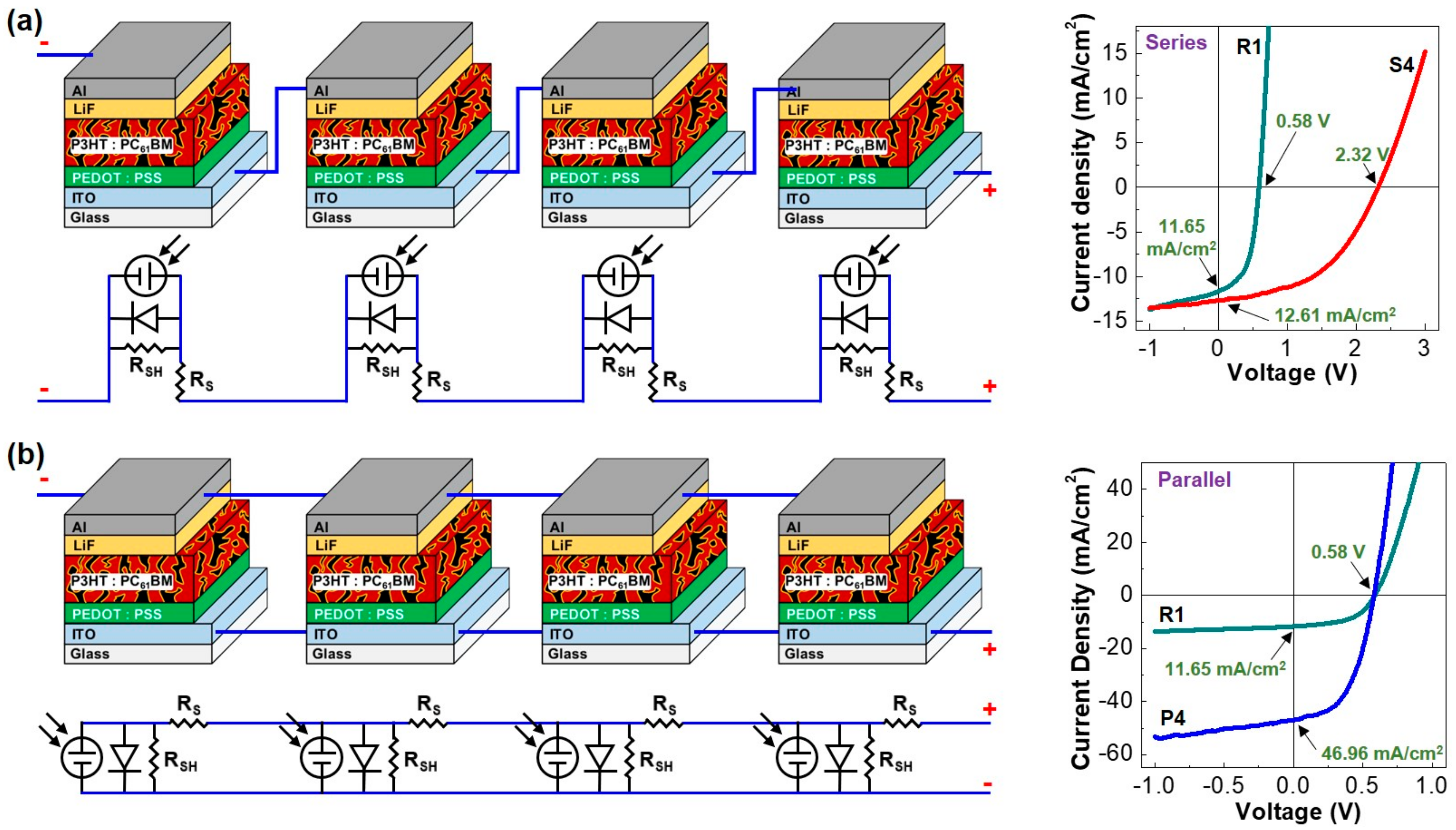
| Parameters | Single Cell (R1) | Four Cells in Series (S4) | Four Cells in Parallel (P4) |
|---|---|---|---|
| VOC (V) | 0.58 (±0.01) | 2.32 (±0.02) | 0.58 (±0.02) |
| JSC (mA/cm2) | 11.65 (±0.35) | 12.61 (±0.29) | 46.96 (±0.32) |
| FF (%) | 52.9 (±2.12) | 48.1 (±2.31) | 51.1 (±1.94) |
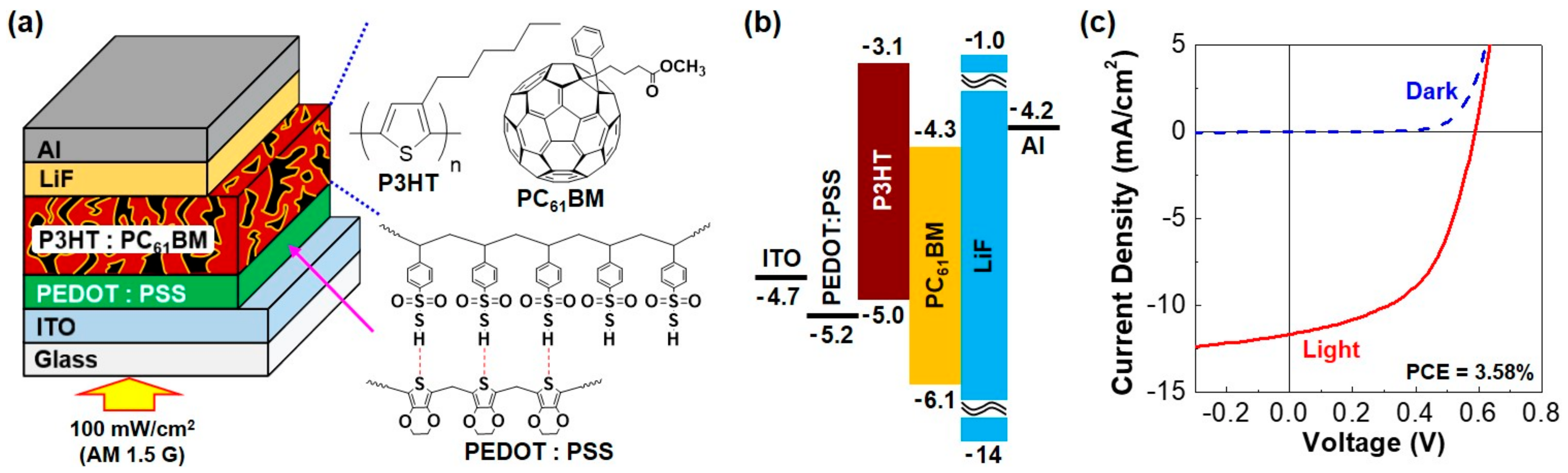
| PCE (%) | 3.58 (±0.21) | 3.52 (±0.19) | 3.48 (±0.22) |
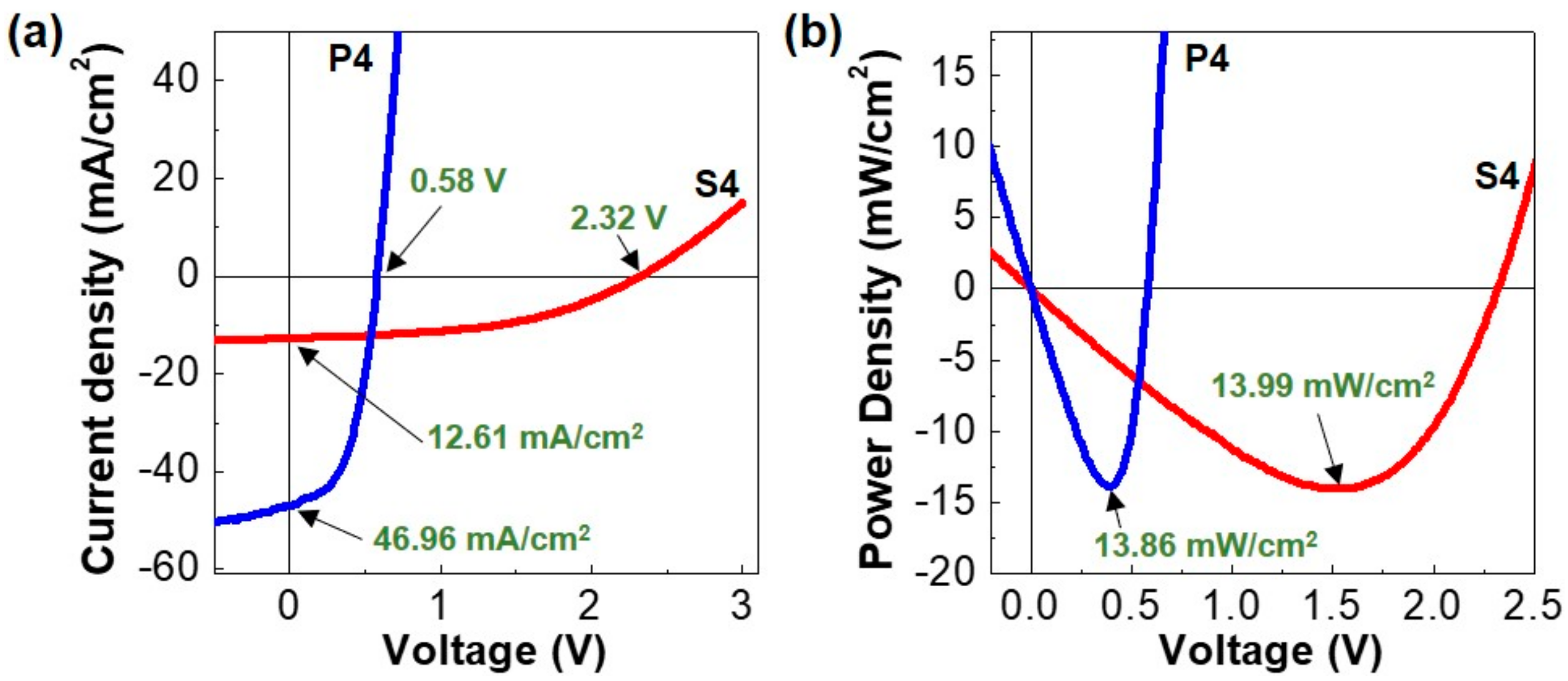
| Parameters | Single Cell (R1) | Four Cells in Series (S4) | Four Cells in Parallel (P4) |
|---|---|---|---|
| PMM (mW/cm2) | 3.58 (±0.17) | 13.99 (±0.27) | 13.86 (±0.31) |
| PMT (mW/cm2) | 3.58 | 14.32 | 14.32 |
| DMP (%) | - | 2.3 | 3.2 |
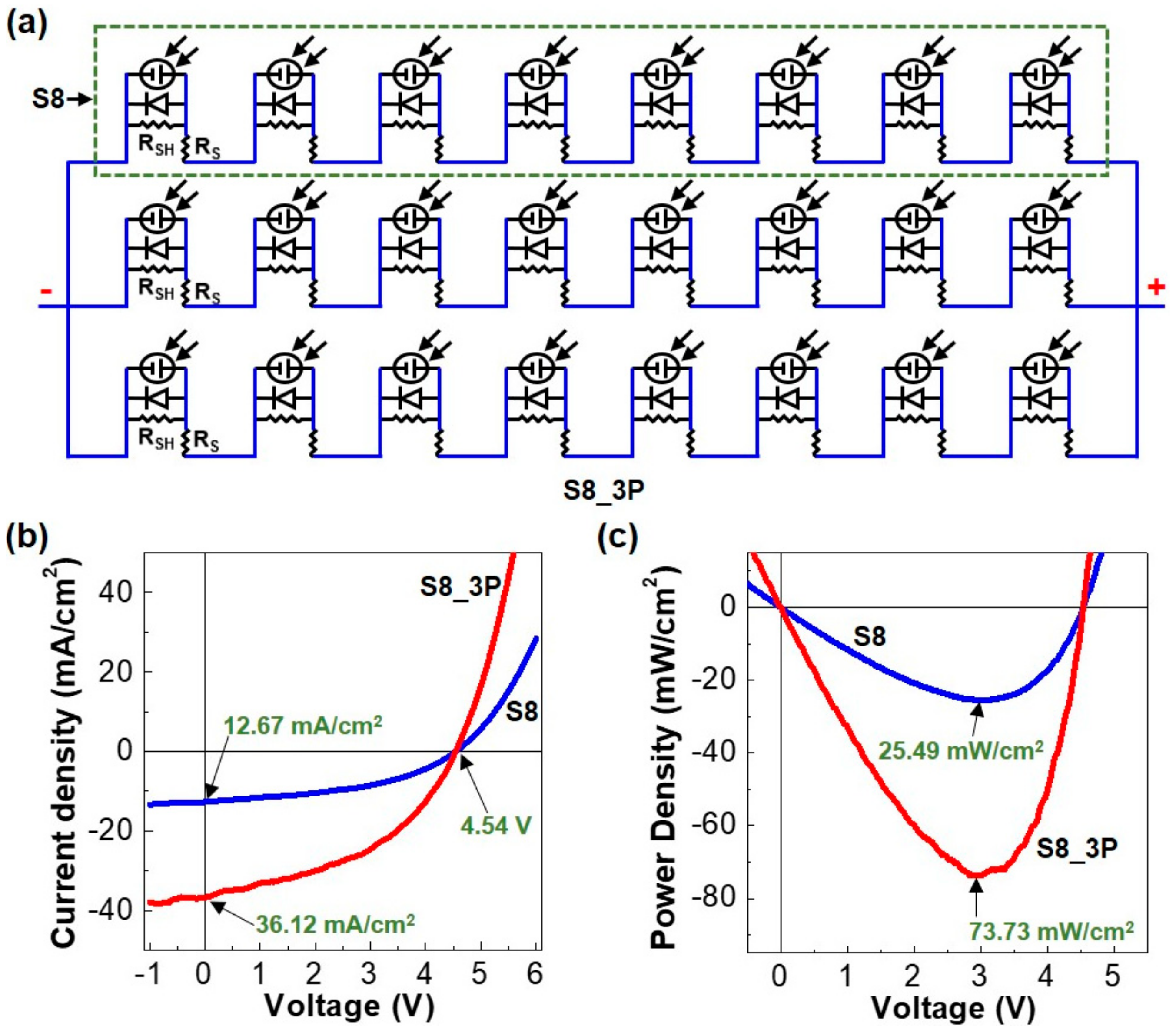
| Parameters | S8 (Eight Cells) | S8_3P (24 Cells) |
|---|---|---|
| Voc (V) | 4.54 (±0.03) | 4.54 (±0.03) |
| Jsc (mA/cm2) | 12.67 (±0.38) | 36.12 (±0.44) |
| FF (%) | 44.3 (±2.31) | 46.6 (±2.19) |
| PCE (%) | 3.19 (±0.29) | 3.06 (±0.32) |
| PMM (mW/cm2) | 25.49 (±0.42) | 73.73 (±0.44) |
| PMT (mW/cm2) | 28.64 | 85.92 |
| DMP (%) | 11.0 | 14.2 |
© 2017 by the authors. Licensee MDPI, Basel, Switzerland. This article is an open access article distributed under the terms and conditions of the Creative Commons Attribution (CC BY) license (http://creativecommons.org/licenses/by/4.0/).
Share and Cite
Song, M.; Lee, S.; Kim, D.; Lee, C.; Jeong, J.; Seo, J.; Kim, H.; Song, D.-I.; Kim, D.; Kim, Y. Charging Characteristics of Lithium Ion Battery Using Semi-Solar Modules of Polymer:Fullerene Solar Cells. Energies 2017, 10, 1886. https://doi.org/10.3390/en10111886
Song M, Lee S, Kim D, Lee C, Jeong J, Seo J, Kim H, Song D-I, Kim D, Kim Y. Charging Characteristics of Lithium Ion Battery Using Semi-Solar Modules of Polymer:Fullerene Solar Cells. Energies. 2017; 10(11):1886. https://doi.org/10.3390/en10111886
Chicago/Turabian StyleSong, Myeonghun, Sooyong Lee, Dohan Kim, Chulyeon Lee, Jaehoon Jeong, Jooyeok Seo, Hwajeong Kim, Dong-Ik Song, Donghyun Kim, and Youngkyoo Kim. 2017. "Charging Characteristics of Lithium Ion Battery Using Semi-Solar Modules of Polymer:Fullerene Solar Cells" Energies 10, no. 11: 1886. https://doi.org/10.3390/en10111886