Review

Progress on Protection Strategies to Mitigate the Impact of Renewable Distributed Generation on Distribution Systems

by
Mohamad Norshahrani
1,2,
Hazlie Mokhlis
1,*,
Ab. Halim Abu Bakar
3,
Jasrul Jamani Jamian
4 and
Shivashankar Sukumar
5
1
Department of Electrical Engineering, Faculty of Engineering, University of Malaya, 50603 Kuala Lumpur, Malaysia
2
Public Works Department, Menara Kerja Raya, Jalan Sultan Salahuddin, 50580 Kuala Lumpur, Malaysia
3
University of Malaya Power Energy Dedicated Advanced Centre (UMPEDAC), Level 4, Wisma R&D UM, University of Malaya, 59990 Kuala Lumpur, Malaysia
4
Faculty of Electrical Engineering, Universiti Teknologi Malaysia, 81310 UTM Johor Bahru, Johor, Malaysia
5
Institute of Power Engineering (IPE), Universiti Tenaga Nasional, Jalan Ikram-Uniten, 43000 Kajang, Selangor, Malaysia
*
Author to whom correspondence should be addressed.
Energies 2017, 10(11), 1864; https://doi.org/10.3390/en10111864
Submission received: 12 October 2017 / Revised: 28 October 2017 / Accepted: 9 November 2017 / Published: 14 November 2017
(This article belongs to the Section F: Electrical Engineering)

Abstract

:
The benefits of distributed generation (DG) based on renewable energy sources leads to its high integration in the distribution network (DN). Despite its well-known benefits, mainly in improving the distribution system reliability and security, there are challenges encountered from a protection system perspective. Traditionally, the design and operation of the protection system are based on a unidirectional power flow in the distribution network. However, the integration of distributed generation causes multidirectional power flows in the system. Therefore, the existing protection systems require some improvement or modification to address this new feature. Various protection strategies for distribution system have been proposed so that the benefits of distributed generation can be fully utilized. This paper reviews the current progress in protection strategies to mitigate the impact of distributed generation in the distribution network. In general, the reviewed strategies in this paper are divided into: (1) conventional protection systems and (2) modifications of the protection systems. A comparative study is presented in terms of the respective benefits, shortcomings and implementation cost. Future directions for research in this area are also presented.

1. Introduction

In line with the concern about sustainability and environmental issues, distribution systems nowadays are continuously being connected to distributed generation (DG) based on renewable energy sources. Wind, solar, biomass and mini-hydro are common renewable energy sources used as a DG source to generate electricity. Besides the benefits of being environmentally friendly, DG integration also improves the reliability of electrical supply and contributes to overall lower power loss since its location is close to loads. Despite these benefits, integration of a high number of DG sources will cause new challenges in the protection systems of DNs. Thus, the impact of DG on the DN must be considered carefully in ensuring proper protection design thus allowing it to work effectively [1,2].
In the past, DNs have always been operated based on the condition that there is no DG in the network [3,4]. Most distribution network operators (DNOs) apply a radial feeder system to deliver power to customers. The implemented protection strategies are based on the consideration of unidirectional current flow, or with the small amount of reverse fault current due to motor contribution [5,6]. Injection of power from DG into DNs causes the network to have multidirectional power flows. Subsequently, the existing protection systems become ineffective or even fail to detect faults due to losses of coordination between protection devices such as relays, fuses and breakers [7,8]. The level of protection failure depends on the number of DGs, location, size, and type. In some cases, a complete loss of coordination is recorded, while in other cases the protection coordination simply weakens [9].
Another impact of DG integration is the change of fault current levels. Normally, radial distribution lines only consider the largest fault current from one source which simplifies the fault current analysis. However, when DGs present in the system, it makes the DN to be multi-sourced, and thus there will be possibilities of having more than one fault current direction. This will increase the fault current level and therefore protection coordination settings require some adjustment.
For DNs without DGs, the strategies to mitigate the protection coordination problem have been proven to work well [10,11,12]. On the other hand, for DNs with DGs, the solutions to the protection coordination problem are still being explored. This paper reviews the current progress in protection strategies to mitigate the impact of DGs in distribution networks. This paper is structured according to the following sections: Section 2 illustrates the impact of connecting DGs in a distribution system from the protection perspective. Section 3 and Section 4 analyze the mitigation strategies presented by various authors to overcome DGs’ impacts on the distribution protection system which can be categorized into two main strategies: conventional and modified systems, with discussions on their respective advantages and disadvantages. Section 5 draws readers’ attention to the factors to be considered while connecting the DGs and issues around them, mainly due to planning and operational considerations. Finally, conclusions and recommendations from the review and potential future research work are presented in Section 6.

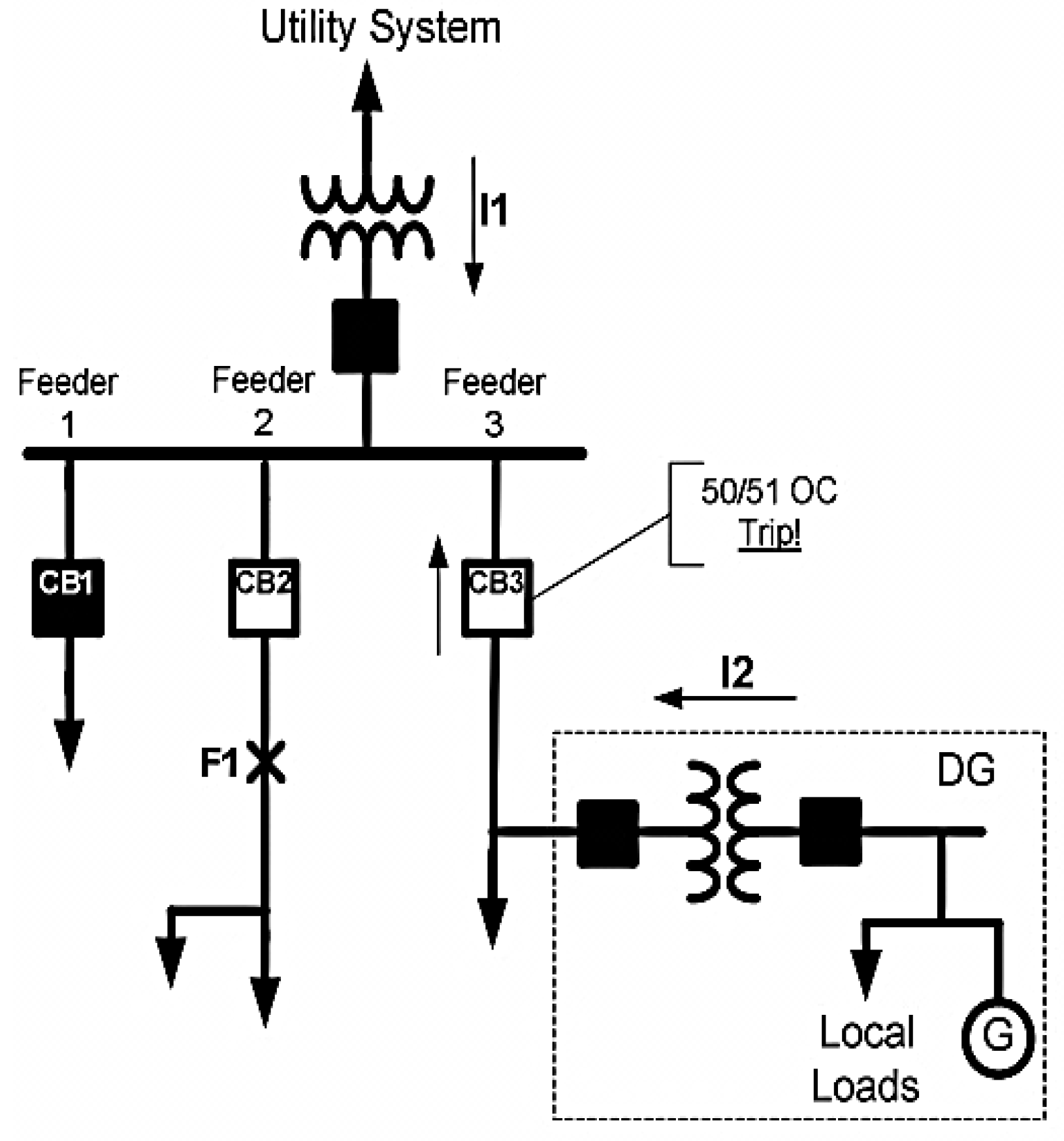
2. Impact of DG on Distribution Protection System Coordination

High reliability of the power supply is the main concern of power system industries. The power utilities need to ensure any new connected load or supply will not harm the network and protection scheme. Therefore, in Malaysia, for example, any new photovoltaic (PV) installation requires approval from Tenaga Nasional Berhad, as a DNO in Malaysia. A power system analysis will be done by the utility before any permit is issued. The control in DG connection is to avoid instability and preserve the security of the DN.
Protection systems are initially designed based on the passive paradigm and only protect in a unidirectional sense. The connection of DGs has changed networks to be active and conventional protection system turn out to be unsuitable for this type of network [13,14,15]. For example, the sensitivity of line protection is reduced when a group of DGs cause reverse power flow. The trip may fail due to the result of forward and reverse current flow which is smaller than the protection setting threshold value. In other words, the reverse power flow can cause a blindness to the overcurrent protection. Furthermore, under certain conditions, if the reverse current from a healthy feeder, which has DGs, to the faulted point (e.g., an adjacent feeder) is too high, it will cause the unwanted tripping health departures [16]. Therefore, the traditional protection schemes might not work successfully with the presence of DGs in DNs.
The worst scenario occurs when the total DG power output is higher than the downstream load. This will cause power flow to the upstream and to the grid site. Similarly, when faults occur in the network, the fault current is only contributed by the sources upstream of the faulted location. However, with the high penetration of DGs, miscoordination problems occur due to the unplanned fault currents contribution from DGs to the faulted point [17,18,19,20]. As a result, the load feeder will see an increased fault current, meanwhile the upstream feeder circuit sees a decreased fault current, which may reduce the sensitivity of the protection system [21]. In addition, the fault contribution from DGs also changes the short circuit levels in the system. In a passive network, the breaking capacity in the downstream feeder is normally lower than that of an upstream feeder [20,22]. However, with the connection of DGs, the fault current might be higher than the breaking capacity of circuit breakers and fuses, thus causing protection system malfunctions. Besides that, the instantaneous overcurrent protection might lose its sensitivity and lead to inadequate tripping [23].
The protection miscoordination between two adjacent feeders can also occur when DGs are installed in DNs. When a fault current occurs at the first feeder, only the protection device located in that faulted feeder should operate. However, the protection device in an adjacent feeder (which has a DG unit) may operate due to the fault current contribution from the DG to the faulted point. This can cause electricity interruptions. Therefore, the coordination between recloser and fuse is likely to be disrupted which causes unnecessary outages in the healthy part of the system [24]. Furthermore, the misoperation protection problems may change the temporary faults to permanent faults, false tripping in feeder and generation unit, protection blinding, undesirable network islanding and prevent asynchronous re-closing [2,14,25,26]. Several methods have been proposed to overcome these problems and most of it will be very costly due to the replacement of protection components such as fuses or protection devices.

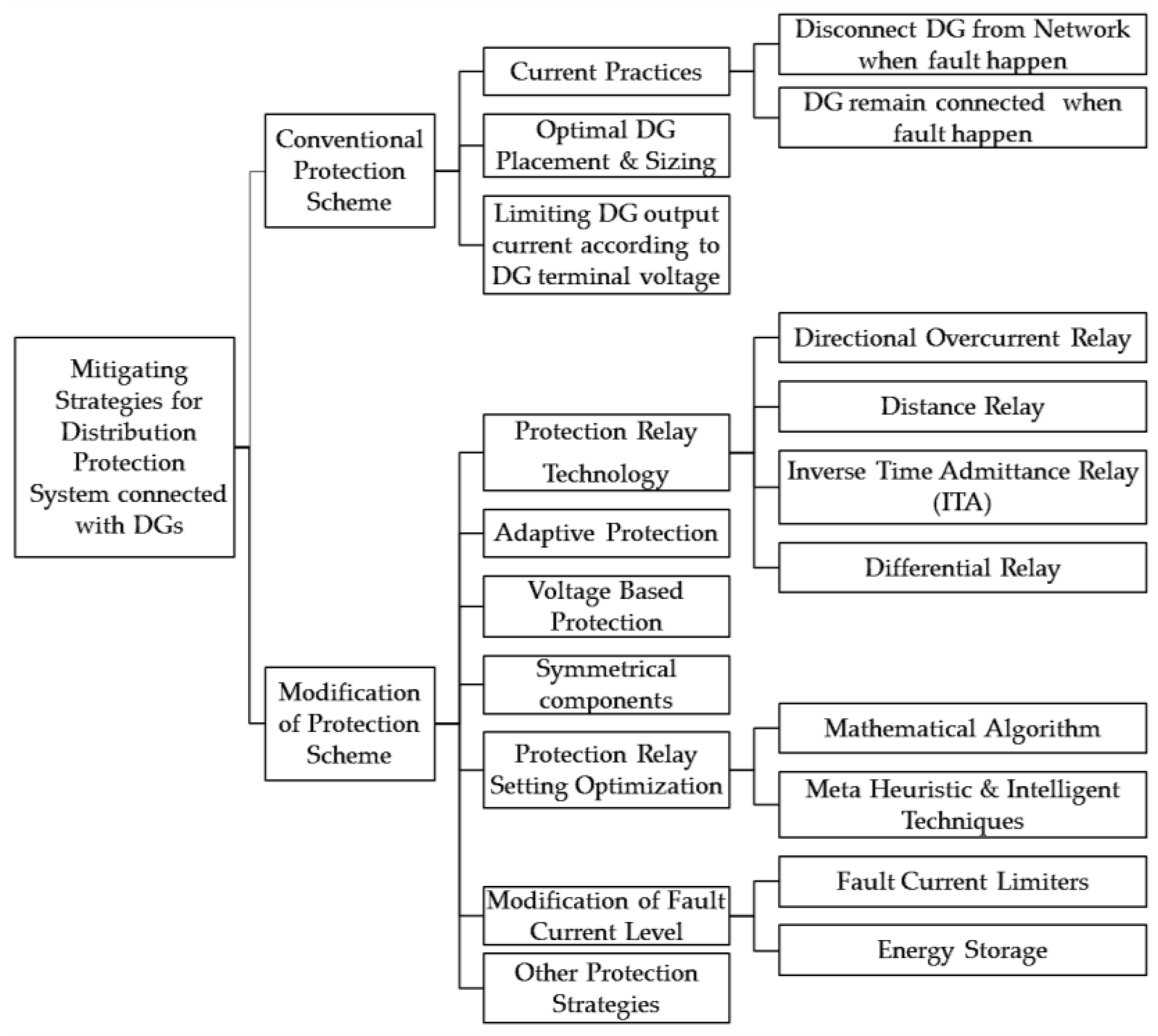
3. Protection Strategies for Conventional Distribution System Connected with DG

In order to overcome the problem discussed in Section 2, various mitigation strategies for protection of DNs connected with DGs were proposed by researchers. The strategies can be categorized into two approaches. The first approach is based on conventional protection with minimum changes, which will minimize the cost and operational disruption mainly to the industrial consumer. The other approach involves modification of the conventional distribution system by introducing additional components related to the protection system. Figure 1 summarizes various mitigation strategies for the protection of DNs connected with DGs.
In this section, a discussion of strategies to mitigate the impact of DG will focus on the aspect of conventional protection schemes. The main motivation behind these protection strategies is to minimize implementation costs. Therefore, the strategies utilize existing conventional protection, switching and sensing device components. This section also covers current practice in the industry and recent progress proposed by researchers. Comparison for type of protection devices, requirements of communication links, cost, advantages and disadvantages of each strategy are summarized in Table 1.

3.1. Current Practices

In general, there are two protection strategies which are being practiced by DNO and DG owners. The first strategy requires DGs to be disconnected from the network when a fault happens. In contrast, the second strategy allows DGs to remain connected when a fault happen. These strategies are based on particular standards developed by international bodies such as IEC and IEEE. It specifies the protection requirement in the Utility Grid Code, prepared by the DNOs, which prioritize reliability of supply to the consumer.

3.1.1. Disconnection of DG When Fault Happen

According to the IEEE 1547–2003 Standard: Interconnecting Distributed Resources with Electric Power Systems, DGs are required to be disconnected immediately when a fault occurs in the DN [27]. Mandatory interconnection requirements of all DG types at the point of common coupling (PCC) having capacity up to 10 MVA has been addressed in the standard. The reason of disconnection is to avoid healthy zones from being affected due to fault [28]. This standard had been applied widely in the Canada and United States [29].
In addition to the above requirement, another standard is IEEE 1574 which applies to PV Power Plants (PVPP) under 10 MVA. The IEEE 1574 standard specifies that when an unintentional islanding incident appears, and the DG continues to energize a portion of the power system (island) through the PCC, the PV system should sense it. Within a period of two seconds it should stop the power generation. This anti-islanding requirement is to protect the remaining network operation which is also a condition in Underwriters Laboratories specification UL 1571, German Standard VDE 0126-1-1 and Australian Standard 4777.3 [30,31,32].
Most of existing practices, especially in North America, require disconnection of DGs when faults happen to avoid islanding [33]. This practice differs significantly for European DNOs which allow islanding operations [34]. In contrast with the intentional islanding which is permitted, the unintentional islanding mode is prohibited in various countries due to reliability and safety factors. In IEEE 1547, a maximum delay of two seconds is given for a DG to sense and detach from an unintentional island as had been practiced in U.S., U.K., and Australian standards. The German standard allows a longer maximum time delay of five seconds [29].
Both approaches either remain connected or disconnected during fault, and have their advantages. For a conventional DN the best option is to disconnect the DG to avoid technical and safety issues. Meanwhile, for a DN equipped with a proper islanding strategy, the best option is to allow the DG to continue energized. This will maximize the DG usage, where it can supply if not all loads some portion of the DN that is healthy. If this can be done, the reliability of the energy supply can be improved. To overcome this issue, the DG must remain connected in order to sustain voltage recovery by having fault-ride-through (FRT) capability [35].

3.1.2. DG Remains Connected When Faults Happen

In this case, DGs are enabled with FRT capability to avoid disconnection from the islanded network resulting from the occurrence of faults in the network. FRT is predominantly intended to protect consumers’ power supplies and to support the grid during contingencies. FRT is also capable of protecting the DN from being damaged by additional fault currents from DGs. From the DNO’s viewpoint, FRTs can ensure safety for personnel from being exposed to accident or injury during switching operation [36].
Generally, FRT can be achieved by delaying the time to trip the protection device and its sole purpose is to avoid unnecessary disconnection of DGs by riding through short-term disturbances. DN stability can be achieved via FRT capability, particularly in areas with high DG penetration [37]. In [38,39,40], FRT capability had been discussed, focusing on interconnection protection requirement.
Due to the advantages of FRT, various utility grid companies around the world specify their requirements in their grid code to facilitate large DG penetration [41]. For DG of PV types, FRT capability is found different in various countries, as presented in Table 2. It can be seen that most countries allow only short duration of faults which is not more than 150 milliseconds [37]. The FRT capability varies according to the level of DG penetration and stability of the grid.
Figure 2 and Table 3 present an example of FRT for DN in Germany which indicates the FRT requirement for PVDG and its behavior during a fault condition [32].

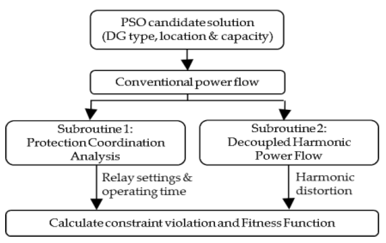
3.2. Optimal DG Placement and Capacity

Researchers had proposed various strategies to find the optimum capacity and location of DGs, so that the protection system will not be affected by the DG connection. For example, by using the optimal power flow (OPF), the limiting factors can be identified. This will assist the DNO to make decisions on further investment, whether to permit more DG in the network or to limit it [44]. In [10], a particle swarm optimization algorithm (PSO) was used to maximize the DG penetration level, with consideration on various aspects including protection coordination constraints, operating time limits of overcurrent relay (OCR) and harmonics distortion levels. The proposed optimization method can be used as a reference in planning works by DNOs. It can optimally allocate different types of DG in DNs, and subsequently reach better penetration levels. The optimum capacity and placement of DGs relied on the constraint; not to violate the operating time and protection coordination of OCR units. This constraint limits the DG penetration level due to the difference in fault current from synchronous-based DGs. The proposed method was tested on the IEEE-30 bus with ten loads and DG scenarios. Nevertheless, in this paper, the authors did not considered variations in investment cost for DG installation. Figure 3 explains the basic framework of fitness evaluation sequence using the PSO technique.
In [45], the technical and economical challenge in redesigning and replacing the existing protection system for a DN considering the growth of DG penetration is analyzed. To overcome it, a strategy was proposed to optimize the DG placement and sizing without modifying the existing protection system. The constraint for this simulation study is based on the existing relay protection system which will set the allowable short circuit currents to protect the DN from false tripping and failure to trip. The proposed method is tested for an IEEE 33 bus system and genetic algorithm (GA) is used to solve this complex problem.
In [46,47], a strategy which focuses only on the optimum size of DG was presented. Mirsaeidi et al. in [47] calculate the DG maximum size at each bus in order to prevent protection miscoordination in DNs. DG capacity was increased and decreased according to the calculated short circuit and relay operating times. Then the relays were graded to ensure the protection coordination requirements are satisfied. The simulation was performed on a typical distribution feeder using the DIgSILENT software package.
Similarly, the authors in [46] also determined the DG optimum size based on an optimization method by allowing for a set of constraints, formulated to keep the protection coordination in the DN. Power losses and system voltage limitations are also being considered to avoid adverse effects to the existing system. The result shows that protection coordination constraint dominates the line loss constraint. If it is not being considered, a larger DG size can be achieved but it will cause failure in the protection coordination.
In [48], the optimal status of sectionalizing and tie-switches are identified using a binary PSO. In order to ensure the protective devices are coordinated due to the presence of DG, the authors had developed a graph theoretic method to preserve the radial topology constraints of the DN.

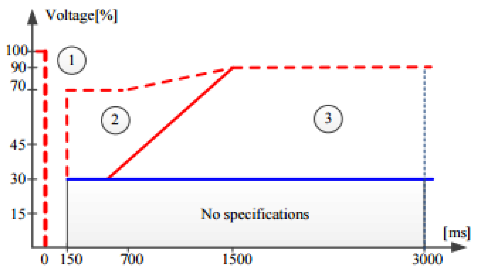
3.3. Limiting DG Output Current According to DG Terminal Voltage

The authors in [40,49] introduced a method to prevent the negative impact caused by inverter-based DGs towards DN protection systems. This was achieved by limiting the DG inverter output current in accordance with the DG terminal voltage. This control method is simple and effective to avoid the fault from DGs and subsequently avoiding its impact to fuse-recloser coordination. In addition, this method has proved effective against non-fault transient disturbances produced by induction motors starting current and load switching. It should be noted that this method effectively utilizes the DG sizes in the existing DN and at the same time does not involve any modification in the existing DN. Therefore this method is inexpensive and easy to implement.

4. Protection Strategy for Modified Conventional Distribution System Connected with DGs

In this section, discussion on strategies to mitigate the impact of DG will focus on the aspect of modifying the conventional distribution system. Recently, a lot of proposals were presented to expand the DG size without threatening the service quality. Some theories are simple, and some are innovative. The mitigation strategies for this section are presented in the succeeding sub-sections, and their comparison, benefits as well as shortcomings were summarized in Table 4. Basically the strategies are based on protection relays technology, adaptive protection, modification of fault current level, voltage based, symmetrical components and optimization protection relay setting.

4.1. Protection Relays Technology

The following subsections describe a few protection strategies using relays as main protection components. These consist of directional overcurrent relays, distance relays, inverse time admittance relays, and differential relays.

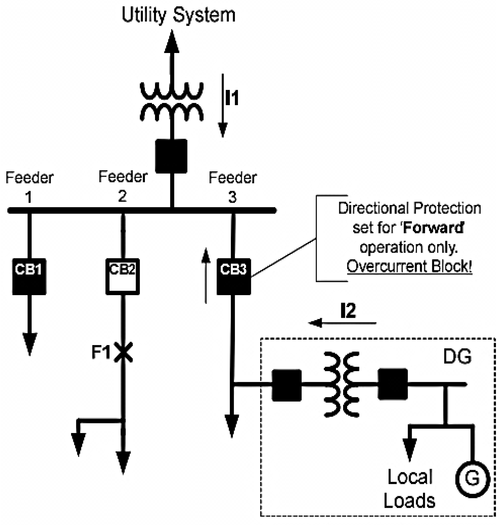
4.1.1. Directional Overcurrent Relays

The connection of DG in DN emulates the concept of transmission networks (TN) as a non-radial circuit. The protection philosophy of TN applies directional and distance protection fundamentals to identify the faults, even in the case of various fault current sources [50]. Prior of radial feeders been connected to the DG, directional features must be well-thought out due to the fact that traditional overcurrent relays are incapable of sensing bidirectional current flows. Hence, in order to mitigate the risk of protection line failure in DNs, the original protection components are recommended to be enhanced with directional overcurrent relays (DOCRs) [34,51].
Antonova et al. [34] explained the unwanted false tripping impact and its mitigation strategies by using directional elements which will only permit the feeder relay to trip due to forward fault, i.e., from load to source. Figure 4 and Figure 5 explain the difference between a robust and weak protection system by using overcurrent relays with and without directional elements. In Figure 4, the fault current (F1) will also cause CB3 to trip due to a false tripping effect when its Non-Directional Overcurrent Relay (NDOCR) senses the fault from adjacent feeder No. 2. This scenario usually happens for DGs connected with synchronous-based DGs. However, Figure 5 shows good coordination selectivity by using a DOCR instead of a NDOCR. The DOCR for CB3 only senses a forward fault and thus did not trip due to the impact of the fault happening at the adjacent feeder No. 2.
Jones et al. in [52] highlighted that traditional setting of the directional element will cause a reliability threat at various VAR flows depending on DG types. They demonstrated the drawbacks of NDOCR and the consequences of improper configuration for directional elements. The authors solved these problems with a unique solution using DOCR with an additional load encroachment function and performed a simulation in a renewable plant collector under various operating conditions. Future recommendations for upgrading works on protection relay were made, in which DNOs must install additional devices which have overcurrent supervisory capabilities to mitigate this impact.
In 2015, Zeineldin and his team [53] further explored the prospect of a directional relay, this time in meshed DNs, utilizing dual setting DOCR. A strategy using dual setting of DOCRs was suggested to protect the meshed DNs attached to DGs. The dual setting relays are programmed with two inverse time-current characteristics. These settings will be according to the flow of fault and formulated using an optimization nonlinear programming. The proposed setting was compared against conventional single setting directional relay and applied to IEEE 30-bus system consisting of synchronous and inverter-based DGs. This strategy significantly decreased by approximately 50% the total relay operating time, regardless of the DG placement and capacity. However, on the other hand, this strategy increased the cost in terms of its additional relay features.
A year later, a strategy in terms of planning scope for future DG installations was proposed in [54] to avoid protection miscoordination which traditionally requires frequent modifications in relay settings. This strategy avoids the frequent setting modifications by incorporating constraints in a linear programming problem which is capable to ensure protection coordination for different DG sizes. This had allowed the DG size to achieve the maximum planned value and minimize the total relay operating time. Another benefit for this approach is that it can optimally identify a set of relay settings which is safe to be used for all various DG future planning situations.
Despite the benefits of DOCRs, the authors in [50,55] highlighted their drawbacks in terms of cost, fault current and unwanted tripping. Mitigating the protection impact using this strategy will increase the cost when the protection components had become double in that it requires two relays, two current transformers and two circuit breakers for each DG embedded in a DN. Since the DOCR still operates based on fault current, the issue of low fault currents from inverter-based DGs arises as a result of inadequate thermal inertia in power electronics switches. This issue will make the distribution protection scheme become uncoordinated. Another disadvantage is the false tripping impact at the upstream feeder end, which may occur when DG feeding faults on adjacent feeders which are using the NDOCR. Therefore, it is recommended that directional elements are featured in all OC relays in distribution lines connected with DGs with setting on forward operation only to block the fault from adjacent feeders [50].

4.1.2. Distance Relays

Despite the advantages of DOCR, it has some difficulties to be applied and has a constraint to set the relay for all DN scenarios. This led to a more complex DN in which changes in generation and system configuration resulted in multiple fault current levels in the system. In contrast, the distance relay setting is constant to various external modifications in DN lines [56]. Typically, in a TN protection system, the priority is to use distance relays. However, recent research has also suggested the use of distance relays for distribution protection. Naturally, distance relays pose a directional element, thus being suitable for closed-loop and mesh systems. The drawback of distance relays is the requirement for a voltage transformer which contributes to a substantial additional cost compared to typical NDOCRs.
Figure 6 shows the main components of an adaptive digital distance relay. A disturbance or a fault in the distribution line is first detected within the protection zone before being analyzed further. In adaptive distance protection, the outputs from the fault detection unit, fault classification unit and fault measurement unit will be analyzed by the adaptive setting unit. Compared to conventional distance relays which only refer to a default setting to determine the trip signal, the adaptive distance relay refers to both the default setting and adaptive setting [57].
The authors in [58] suggested a quadrilateral characteristic of distance relays to overcome the influence of reverse power flow in DNs integrated with DG. Aiming to minimize the complexity issues of protection coordination for feeder protection with multiple sources, the authors in [59] also proposed a protection strategy by using distance relay technology.
Several utilities [60,61] require a distance relay as specified in their DG interconnection standard. Hydro-Quebec (a Canadian electric utility company, Toronto, ON, Canada) prohibits the use of NDOCR as the primary protection. However, they require an installation of distance relay to overcome the issues of intermittent power supply from DG and loss of supply from DGs due to DG internal operations [62]. From the aspect of stability, another advantage of distance relays is a shorter operation time compared to conventional NDOCRs. However, deciding the distance relay settings could be more difficult procedure than for conventional relays, in which distance relays are designed to avoid fault under-reach or over-reach during phase-to-earth faults.

4.1.3. Inverse Time Admittance Relays (ITAs)

In general, there are three types of distance relay which are prominent for their usage and operating characteristics, i.e., impedance, reactance, and admittance. The most common being used is the admittance relay [56]. Dewadasa et al. [63,64] had proposed a mitigation strategy based on an admittance relay, but enhanced it with inverse time tripping characteristic, and named it inverse time admittance relay (ITA). ITA relays are capable of distinguishing and isolating the faults in both grid-connected and autonomous micro-grids [65]. By decreasing the output voltage of the converter, the ITA relay restricts the fault current according to the affected phases. Subsequently, by analyzing the fault characteristics, the sequence currents and voltages at the relay positions can be measured. Simulations were done to various faults types at different positions according to changes in types of load and fault resistance. In order to reduce the output voltage, the admittance relays proposed in [66] protect the feeder segments of a radial microgrid connected to the utility network via back-to-back converters against the three-phase-to-ground fault.
In [63] it was highlighted, that due to the current limiting features of converters, the relay may fail to sense a small fault current. Hence, ITA relays were introduced with further explanation on their reach settings. In addition, an approach to compensate the fault resistance in order for the relay to operate reliably is suggested. This relay has numerous benefits over the traditional overcurrent and distance relays. A year later, Dewadasa [64] proposed ITA relay characteristics with fold back current control in which the amount of line admittance will determine the relay operating time. By measuring the admittance, this makes the relay become sensitive on the fault location. Recently in [67], authors presented an ITA relay which able to sense multiple fault levels in DNs. This proposed ITA relay has various improvements compared to the existing overcurrent and distance relays. It can isolate faulty sections on the upstream at the feeder and downstream region without affecting the DG based on admittance measurement. This relay’s inverse time characteristic does not use safety margins which expedites the protection devices’ tripping time. Nevertheless, the impact of this proposal has not been validated in real DNs.

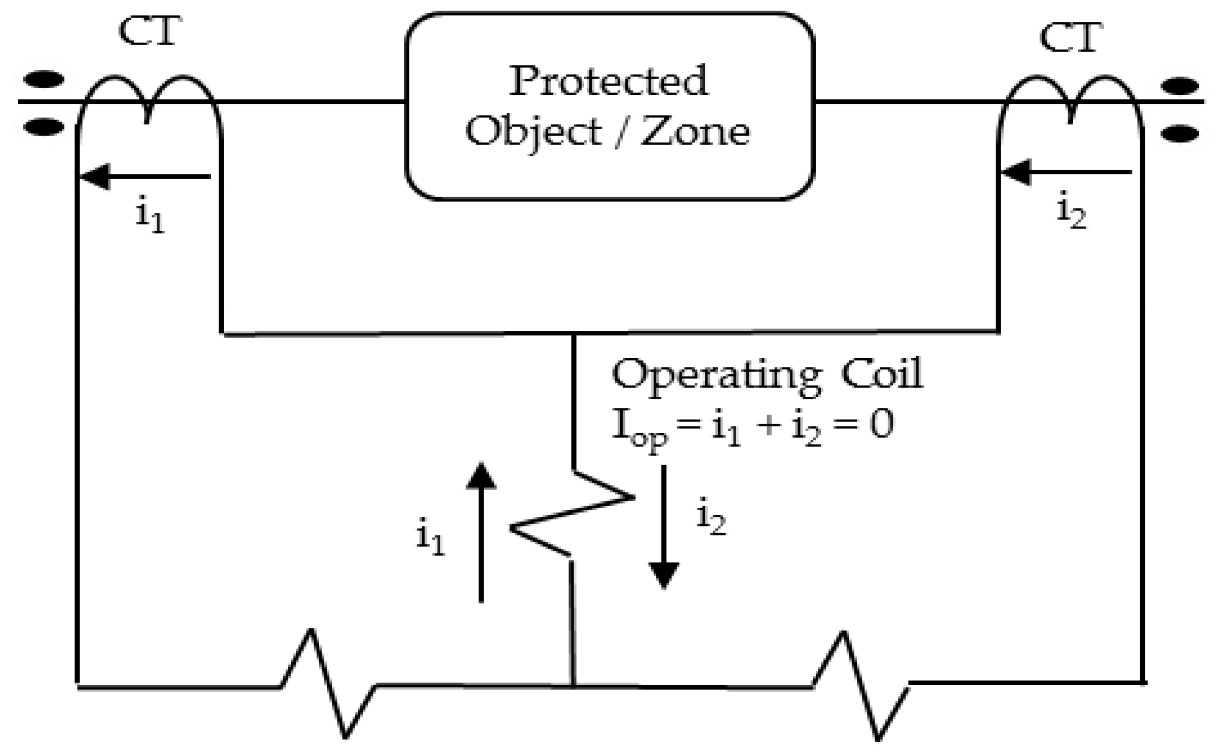
4.1.4. Differential Relays

The operational concept of differential protection is illustrated in Figure 7 which is established from Kirchhoff’s Current Law. The summation of currents in the secondary CT (i1 + i2) will determine the relay operation. In normal conditions or due to a fault outside the protection area, the sum of current in both CTs is opposite in phase and equal in magnitude, hence no current will be flowing in the relay operating coil. However, when a fault occurs between the two CTs, the relay will trigger the circuit breaker to trip due to the current which now flows in the coil. For a large protection area, a communication system is needed to transmit the value from the CTs to the relay.
References [68,69] propose an implementation of differential protection for DNs with DG. In [68], the impacts of bidirectional current flow and multiple fault current level caused by the intermittent nature of DG was taken care by the proposed mitigation strategy using a differential relay. Simulations using various relay settings and selections of CT characteristics were proven capable of locating the fault without modifying other relay settings. This strategy offers good discrimination and high sensitivity towards internal faults. Looking ahead towards risk of communication failure, this strategy was proposed with a primary and a backup protection.
A design concept based on a central protection system was proposed in [69] which utilizes the advantages of differential current protection. With the central system, DNO able to determine different restraint current calculation algorithms and to adjust the multi-terminal zone protection due to the modifications in DN topology. This proposed strategy found to be more reliable than the traditional differential protection strategy.
The advantage of differential protection is the flexibility in the protection aspect. Due to its operation concept of the internal zone of protection, it does not require information on the fault currents from the DN analysis which simplifies the protection coordination. The significant advantage of this strategy is due to its insensitivity towards bidirectional current flows. However, the differential protection method is difficult and expensive to apply in DNs due to the large number of lines. Each line needs to be equipped with a differential relay, together with the communication links between the relays. The operation of this mitigation strategy has still not been experimentally validated [70]. Due to the fact that communication system is one of the main components to differentiate the current value, thus the risk of its failure must be highly considered with a secondary back-up protection scheme, which make it relatively expensive.

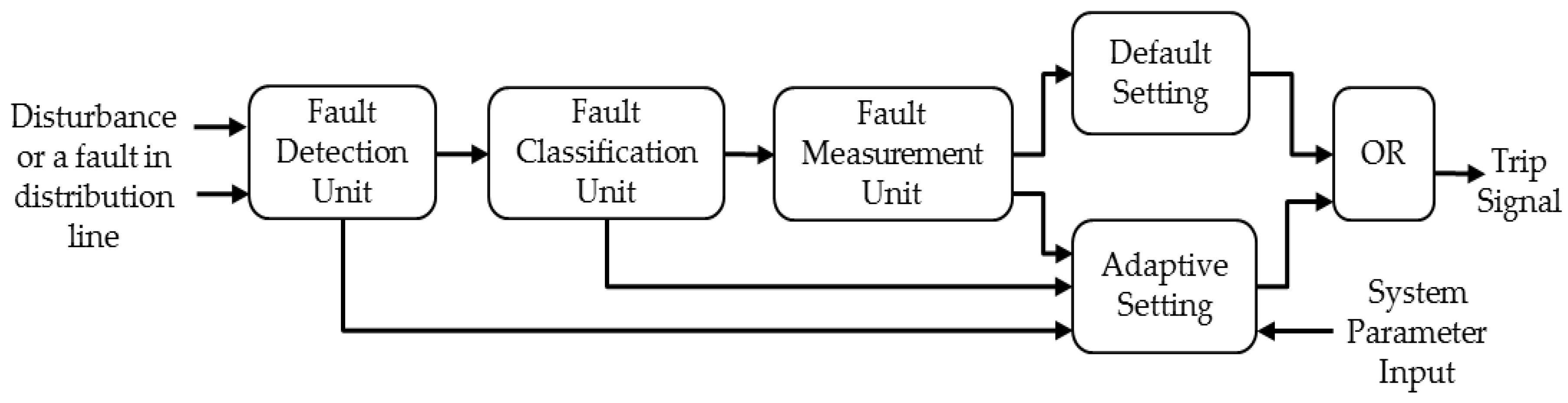
4.2. Adaptive Protection

Adaptive protection enables relays react to any changes in the DN. To achieve this, a good communication medium is needed to continuously update important information such as currents and voltages in the DN. In conventional protection systems, technicians are required to be at the site to reset the relay settings when required due to any changes in the DN. However, the presence of technicians is not required anymore since modern DNs are equipped with automation and monitoring capabilities. Nevertheless, due to the safety factor, DNOs prefers to assign technicians in case the situation requires human intervention [34]. This section presents the implementation techniques in making the relay adaptive with the help of communication infrastructure and communication protocols.
The crucial issue in deciding the relay settings is to achieve the minimum possible operating times while maintaining coordination among all relays. Dynamic relay settings are useful in managing the operation and protection coordination in DNs with DG. In contrast with conventional methods, dynamic relay settings can be changed automatically in terms of current and time setting with suitable margins. Some Intelligent Electronic Devices (IED) with loop control monitoring have automatic setting group features which are capable of adjusting the relay setting according to the fault conditions. Dynamically, due to the numerous placements of DG, the multiple relay settings can be done according to each group scenario including the value of pickup current and the directional settings.
Adaptive protection schemes enable different micro-grid topologies to be protected against all fault situations. The pre-calculated relay settings for various topologies are saved in the memory storage. Whenever the topology changes, the relays are updated with their new settings from the database. A new generation of relays is able to create at least 6 groups setting to assist proper relay coordination in DN which has improved the relay sensitivity and maintain its selectivity [34,71].
The authors in [72] simulated dynamic settings in adaptive protection using a traditional relay-recloser-fuse combination with digital relays and reclosers. The new adaptive protection coordination curve was drawn by the relay through an algorithm that senses the DG location according to the relative current magnitudes. This strategy is effective for a limited number of DGs only. As the number increases, the protection coordination curves become close to each other and lead to unwanted tripping. Furthermore, the cost to establish the communications and measurement instrument is very high. In [73], dynamic relay setting was proposed for switching of the source from grid connected to island and vice versa by using an automatic readjustment relay settings. The relay setting changes accordingly in terms of time and pickup current to suit the DN conditions. In order to provide more effective protection, a communication system can be applied in order for each relay to interact and exchange information between each other and with a central computer [65].
An adaptive protection strategy is recommended in [36] where a micro-grid control center (MGCC) is connected to a DOCR at each bus via a communication system. The off-line study is implemented by creating event and lookup tables for the protection device statuses and relay settings in all MG configurations. The MGCC observe the MGs operating state and analyzes the event and lookup tables to coordinate the relays. In real-time operation, the computed current is matched with the relay settings to detect the presence of a fault. The flow of fault current is analyzed with the present interlock direction to locate the fault. This scheme adapts to several MG configurations. Protection is provided for all fault types. The communication system speeds up the operation of the scheme. However, this strategy is not efficient for larger MG configurations due to excessive memory used to store large amounts of off-line data. In addition, it does not protect against HIFs and the connection of new loads and DGs has not been considered.
Laaksonen [74] presented an adaptive protection strategy for an LV MG where a communication system is connected to the MG Management System (MGMS) and various MG components. Protection strategies for both the grid-connected and islanded modes are developed for components which include the LV feeders, loads, point of common coupling (PCC), and DG units. The MGMS senses the change in the configuration and transmits the suitable settings and pick-up limits to the protection devices for every component. The drawbacks in this strategy are the risk of communication network failure and the lack of a plug-and-play DGs concept feature.
In [75], Conti highlighted the practice of an Italian DNO which used telecontrol or automation techniques. The works proposed a minimum implementations cost to the DNO by using the traditional protection devices including telecontrol or automation systems. For a micro-grid network, with the assumption all relays in the DN have been upgraded to digital type, researchers in [76,77] proposed strategies to utilize a centralize computer system to review and update the relay setting values for the objective of retaining the protection coordination between the relays, though, within the short period of network reconfiguration and the new relay setting calculation, the protection coordination possibly will not operate [78]. In [79,80] the authors highlighted that in practice, adaptive protection which required an IED, and high-speed data communication system will involve high investment costs to replace the traditional relays and to add a communication system.
In the early days of protection systems using a communication system, different protocol languages were used by various power utilities. At the beginning, it was a huge challenge to integrate the various protection devices from different manufacturers [81]. However, the emergence of IEC61850 as an international standard communication protocol has expedited the development of communication systems in DNs. IEC61850 is applied to transmit the critical data such as Generic Object Oriented Substation Event (GOOSE) and Sampled Values (SV) of currents and voltages. Data between relays, DG protection devices, and IED can be shared to determine the required relay setting adjustment according to the protection setting group [81].
A centralized adaptive protection strategy for a MG was proposed by Ustun et al. [82]. This strategy works well with the MG component models based on IEC 61850 and IEC 61850-7-420, but it is not suitable for complex systems with changing relay connections. Another disadvantage is that this strategy did not consider the dynamic behavior of the communication system.
The most challenging part faced by a DNO upon the introduction of the DG is how to maintain safe and reliable communications among each device. Although IEC 61850 GOOSE messages have been used by the industry, however, the concern is about the higher cost due to the needs to connect all the devices belonging to customers, especially for metering purposes. Another concern that needs to be highlighted is the communication technologies which change very fast. For instance, GOOSE messages to control the DG can be transmitted via WiMax (Worldwide Interoperability for Microwave Access) technologies. However, there is a constraint on the buffer size for some WiMax devices which are incapable of carrying defined GOOSE repetition rates. Furthermore, DNOs must be more cautious in the administration of the configuration, management and management of the communications infrastructure [83].

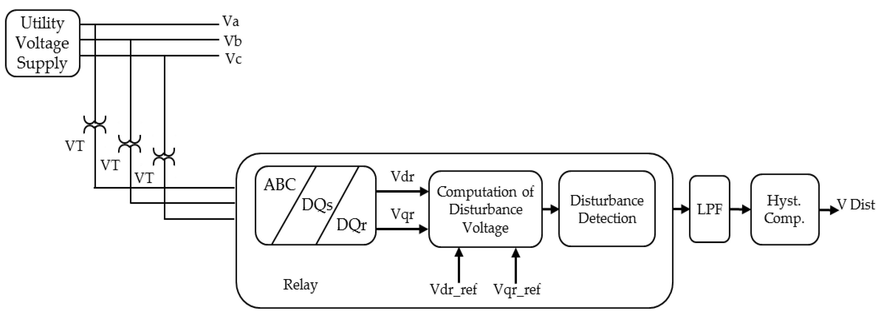
4.3. Voltage-Based Protection

Voltage-based protection techniques such as those described in [84,85,86], use the voltage measurement in the DN to identify the faults in the system. The DC quantities from the d-q reference frame of the measured voltage are used to identify the faulty sections and protect the DN against different types of faults [84,85]. The measured voltage in the DC quantity is compared with predetermined threshold quantities. If it exceeds the value, the faulted zone is tripped and the type of fault is identified. Typical implementation of a voltage-based protection scheme is shown in Figure 8.
A voltage-based protection scheme utilizing the voltages from the park transformation is proposed in [87]. The proposed method has the ability to protect DN against three phase, two-phase and single-phase to earth faults. The method does not utilize communication links. However the operation of the protection scheme could be optimized when communication links are provided. In [88] a protection scheme based on bus bar voltage is proposed for both grid connected and islanded DNs. Although the voltage-based methods are capable of detecting faults in and out of the protection zones within the DN, they are unable to detect high impedance faults (HIF) and symmetrical faults. In addition, the need for effective communication links is essential to implement the voltage-based protection for DNs.

4.4. Symmetrical Components

These protection strategies mainly utilize symmetrical current components for analysis in order to provide protection for the existing DN. A fault protection scheme for DNs was proposed in [89], that uses both zero and negative sequence current components to identify the fault scenarios. In [90], a positive sequence-based protection for DNs consisting of inverter-based DG sources is presented. The proposed method can detect faults and does not require synchronous fault data measurements beforehand.
Protection strategies utilizing sequence current components were used to protect DNs from the the effects of reverse power flows. Very recently, a protection strategy based on sequence current components was introduced by the authors in [91] to detect the reverse power flow in spot DNs with high DG penetration. In addition, a positive sequence fault component-based pilot protection scheme is devices in [92] for the protection of closed loop DNs with DG. Figure 9 shows s typical configuration of s closed loop distribution network with two busbars M and N. The configuration consists of remote thermal units (RTU) which are installed in each ring network cabinet (RNC). The RTUs can monitor both the voltage and current flow between bus bars. Master station (MS) monitors all the RTUs in the system and makes decision on steps to recover the system.
This protection scheme also includes protection against reverse power flow that is caused due to the large penetration of DGs in the DN. Although these symmetrical components-based protection strategies is proved to be effective, the necessity for strong communication links have made it difficult to implement it in real time. Moreover, in case of communication link failures, the protection coordination may be disrupted, which may prove costly.

4.5. Protection Relay Settings Optimization

In previous Section 3.2, strategies to find the optimum capacity and placement of DG were introduced to mitigate the impact of DG on conventional DNs which are using existing overcurrent relays as their main protection component. However, in this section the mitigation strategy is still using an optimization approach, but with a focus on strategies to find the optimum protection settings value, with consideration on using additional protection components such as DOCR and FCL. Optimization methods in protection coordination involve a system configuration on DN with the problem being formulated as a linear or nonlinear programming problem, and resolved via the simplex method as well as its variants. Compared to the optimization of DG size and location which is a popular topic among researchers, works on finding the optimum protection settings for DNs with connected DG are still few in number. Among the recent methods proposed by the experts are the mathematical algorithms, genetic algorithms, modified particle swarm optimization, ANN and expert systems. These optimization techniques are applied together with other protection devices in order to achieve the most significant protection strategy for the dedicated system. Researchers keep on exploring new optimization algorithms and techniques to achieve the optimum relay setting values which results in a fast and reliable distribution protection system.

4.5.1. Mathematical Algorithm Approach

Mathematical algorithms is based on numerical calculations, which are derived from mathematical equations. Researchers have studied the new setting algorithms which depend on optimally designed objective functions and protection components as one system. Recently, research [93,94,95] on this approach is mostly done using DOCR as the main protection devices due to their advantages as described in Section 4.1.1, but with a different algorithm. Each algorithm was introduced as an optimization method to obtain the correct and quick setting of all protections in a DG network.
Ehrenberger et al. [93] focused on optimization based on DOCR with inverse-time characteristics. They proposed a quick optimization automatic algorithm with the objective function, in line with the topical system configuration and validated using simulation in SIMPoruchy 2.1. As the network system configuration had become specific, this algorithm can perform a quick setting for an adaptive protection scheme.
A more complex mathematical algorithm using a Modified Electromagnetic Field Optimization algorithm (MEFO) was used in [94] which solved the DOCR optimal coordination problem using an improved version of the EFO. The DOCR optimal coordination problem has been formulated as a non-linear programing (NLP) problem and as a mixed integer NLP according to the nature of the optimized parameters. The results demonstrate that the MEFO is an efficient and reliable tool for the coordination of DOCR and better than those obtained using a number of well-known optimization techniques compared in its reference.
In [95], Zeineldin and his research group proposed a coordination strategy which attained a 50% decrease in overall relay operating time. This mitigation approach applied user defined characteristics for the inverse time DOCR and the problem was formulated as a nonlinear optimization in which each relay will have four optimal settings. The result also interpreted that, regardless of the DG capacity or its placement and the number and locations of fault points, this strategy is capable of reducing relay operating times.
Compared to the above strategy which is formulated as a NLP, more recently, the authors in [54] had to focus on future DG planning scenarios and formulated a linear programming problem. It had a simplex algorithm with application of FCL which can identify a set of optimum relay settings which is effective for every potential new DG installation.

4.5.2. Meta Heuristic and Intelligent Techniques

The meta-heuristic technique is an iterative generation process to identity the most optimal solutions via learning strategies that merges different concepts to scour the search space. This strategy is widely applied to find the exact or near exact optimal solutions. Genetic algorithm (GA) and particle swarm optimization (PSO) are among the techniques in this meta-heuristic category. Meanwhile, artificial intelligence (AI) is a technique which imitates the human logical thinking system and duplicates it to in computer programs which can be used to reconfigure networks such as has been used in expert systems.
A genetic algorithm (GA) is used in [96] to coordinate protection settings of FCL and DOCR in a micro-grid. The complex computational problem was formulated as a constrained NLP problem and GA with the static penalty constraint-handling method is used to solve it. However, one issue that must be considered is whether the proposed coordination times allow sufficient time for conventional synchronous generators to ride through faults and continue in stable operation. In addition to the issues, the low fault current impact contributed by converter-based DG and energy storage devices was not tested on this strategy, thus it become potential work for further research. The protection coordination issues which have many limitations due to coordination requirements were emphasized by Chakor et al. [97]. They highlighted a drawback of heuristic-based optimization techniques which may wrongly converge to points that are not optimum. This happens as a result of challenges to obtain the initial feasible solution and the large parameter range of design variables. For improvement, the optimization problem is formulated as a constrained NLP optimization and determined via GA. Although DOCRs are the most preferred protection components, their function will also deteriorate due to the connection of DNs with DG especially in protection miscoordination. Hence, the authors in [98] suggest a strategy by engaging an adaptive protection scheme using GA. The problem to calculate the optimum values of Plug Setting and Time Multiplier Setting for OC relays was formulated using GA.
In mitigating strategies through optimization of relay settings, the particle swarm optimization (PSO) technique is also applied to improve the protection coordination. In [99], protection coordination was set as a constraint in the optimization process, and the original PSO algorithm was modified in order to deal with the constraint. Compared to the original PSO, the modified PSO is able to find a better optimal solution for the protection coordination issues. Furthermore, for a bigger problem, the modified PSO still manage to find a better solution than deterministic methods. The improvement over the initial PSO algorithm is in the phase initialization part and phase updating part of the PSO algorithm. In MPSO, all particle positions in the D-dimensional space are not moved simultaneously but only one in each dimensional space at a time [100]. In [101], the technique to solve the DOCR coordination issues in DN with DG by using MPSO with a linear programming algorithm was introduced. The objective of the suggested method is to calculate the pickup currents and time dial settings for every DOCR that can reduce the total relay operating times. The proposed method is good in finding the best (fastest) pickup current and time dial settings for the directional relay setting which can protect the distribution network faster and better.
The authors in [102] used an expert system to improve the protection coordination settings in DNs with DG connections. The inference process utilizes the coordination and selection rules to search the optimum coordination settings by referring to the processed data (circuit, equipment, protection, and DG) in the knowledge base. Whenever there is a conflict in the setting, users can overrule it with their own decision. By default, the rules are programmed according to different protection scenarios and can be changed accordingly. This approach is used as a decision tool by DNOs to study the influence of DG on DNs, before modification of the various coordination settings can be done.

4.6. Modification of Fault Current Level

The previous strategies are focused on the aspect of protection coordination and fault detection. Another aspect which can mitigate the impact of DG connection to DNs is the modification of fault current levels. DNs with DGs is usually operated at grid-connected mode, but seamless transition from grid-connected mode to autonomous mode takes place during the event of a disturbance. There is a change in fault current levels in the grid-connected mode and autonomous mode, and the design of suitable protection schemes to ensure safe operation of DNs from these disturbances is a real challenge. In order to alleviate this, there is a possibility to modify the fault current level when the transition from grid-connected mode to autonomous mode happens and vice versa. Application of external devices known as fault current limiters (FCL) and energy storage devices was also suggested by researchers to alter the fault current level.

4.6.1. Fault Current Limiters

Fault current limiters (FCLs) are series elements which have zero or very small impedance during normal operation and the impedance value increases during fault conditions in order to prevent the overcurrent. FCLs detect the fault rapidly and withstand the fault current until corrected. In addition the fault current is cleared with a certain level of power quality. In [103], a central protection system for DNs with DGs, using FCL was proposed to estimate the fault current and to isolate the fault. The protection system utilizes a TCP/IP-based Ethernet communication network to update the currents of the relays and to detect the direction of fault currents in the system. The proposed system can respond to dynamic changes during both grid-connected mode and autonomous mode. A resistive-type superconducting FCL (SFCL) is used in [104] to alleviate the fault current level caused by the impact of DG in DNs. It was found that installing SFCLs at the starting point of feeders may result in reduction of fault current contribution. An optimal utilization of FCL to coordinate the over current relay for a network consisting of DG sources is studied in [105]. Similarly, coordination of over current relays in DN utilizing FCL was reported in [106]. In addition, application of FCL for protection of DNs can be found in [107,108,109].

4.6.2. Energy Storage

The value of the fault current for the inverter-based DG is significantly much less during the islanded operation of DNs with DGs. As a result, protection relays fail to activate the overcurrent protection devices installed in the system. Therefore installing energy storage devices such as flywheels, batteries or capacitors in the DN, can increase the fault current level allowing the protection devices to be operated in a conventional way [36,110]. A coordinated protection strategy using superconducting FCL and superconducting magnetic energy storage (SMES) was devised for DNs with DGs in [111]. This protection strategy can mitigate the impact of solar PV generation for a grid-connected DN. The coordinated use of both FCL and SMES produces the best comprehensive performance with the reduced capacity of SMES. Similarly, a protection scheme was proposed in [112] using FCL with SMES to mitigate the impact of grid-connected DNs consisting of wind turbine system. Some important DN protection schemes considering energy storage devices to modify the fault current level can be found in [113,114,115]. The high cost of energy storage devices is the major hindrance in the deployment of DN’s protection scheme involving these energy storage devices.

4.7. Other Protection Strategies

Other than the strategies explained above, there are also other strategies which focus on interconnection between DNs and DGs, which are worthy of being highlighted here:
  • Inrush current detection is used to avoid unwanted disconnection caused by a 2nd harmonic which is produced when the transformer is energized [34,116].
  • DGs’ rotor overheating can be avoided by applying negative sequence protection [117].
  • Reverse power protection is used to sense the internal fault from DG and mitigate it either by immediately disconnecting from the DN with a time delay, or riding through the fault [118].
  • Auto-reclosure is able to minimize the disconnection impact by auto-reconnecting the DG with the DN depending on a number of faults, especially when due to temporary faults such as surges. However, extra protection needs to be considered to avoid from permanent faults from damaging the equipment [119].
  • Among the lightning impacts on DNs connected with DG are the increase of voltage and change of power flow which affect the protection coordination and selectivity, as well as voltage fluctuations. In [120,121], authors proposed lighting protection strategies to determine the optimum size, location and quantification of the surge arresters to protect the DN.

5. Discussion

This section analyzes and discusses important factors that need to be considered for connecting DG to a DN and issues from a protection perspective. The summary of benefits, drawbacks and comparison of the conventional and modified protection is presented in Table 1 and Table 4, respectively.

5.1. Conventional Distribution Protection System

In the conventional DN protection, there are four strategies that have been discussed. The advantages and disadvantages in terms of technical and cost of each strategy are summarized in Table 1. The most appropriate strategy will depend on the willingness of a power utility in invest in new technology such as islanding detection and FRT. For minimum protection investment, the best strategy is to limit the DG penetration, which must be done during the planning stage. This will keep the operation of the DN with single power flow and meet the existing protection device characteristics. This approach is beneficial for DNOs, but there is a challenge for the DG owner in that the DG output capacity is underutilized. This affects the DG operational efficiency and capital investment.
From the operational point of view, it will be worth to keep with the conventional protection systems when considering low load growth, cheap tariffs, aging DN components and expensive protection device replacement costs. Alternatively, existing protection strategies been practiced which are either to disconnect the DG during faults or ride through the fault can be highly considered in conventional protection system to ensure protection requirements are fulfilled. However, this approach is only practical for a short term due to the growing demand of DG penetration in the future. It is a challenging mission to change the current practice in DNO operation which already safe and secure to a new protection scheme to cater DG penetration impact. Moreover, DNOs need to invest to have this new protection scheme. A lot more studies are needed to convince DNOs to apply this and disturb their current business operations. These disadvantages have attracted more development of potential solutions either to retain or to enhance conventional protection systems as highlighted in the Section 3 and Section 4.

5.2. Modified Distribution Protection System

For modified distribution protection systems, there are six strategies that have been discussed. Their advantages and disadvantages are summarized in Table 4. Among these strategies, choosing the right relay technologies and optimizing the relay setting are the most viable in terms of planning and economics. In planning, ideally, the best protection strategy is to upgrade the protection system by installing additional protection devices and communication systems. For future planning or for a new DN, it is highly recommended to install new DOCRs as it is the best strategy to mitigate the impact of bidirectional power flow. However, the utility company may need to consider the high capital cost and the difficulty to configure the setting values for all contingency scenarios. In the optimization of protection relay settings, most of the proposals focus on finding the optimal protection coordination by using DOCRs. These optimization strategies aim to search for the best (fastest) pickup current settings and time dial settings which can protect the DN faster and more reliably.
A combined strategy using DOCRs with adaptive protection will further improve the protection system and reliability. From the literature, these proposed strategies are sustainable for future growth of DG penetration towards smart grid and micro-grid applications. However, the challenges are the cost and time effectiveness. The decision to equip DNs with new protection devices must consider the capital investment by the DNO and DG owner which will affect the consumer, especially in terms of electricity tariffs. Depending on which strategy to apply, DNOs may have to replace the existing protection devices such as overcurrent relays with new protection devices. At present, DNOs are inclined towards minimum-cost solutions, in line with the concept that DN protection should just be sufficient to ensure safety and minimize damage. A good planning within a time frame to enhance the DN with suitable protection strategies will help the DNOs prepare for the future.
As presented in the literature, most of the proposed protection strategies are applicable to DNs with dedicated topology and specific types of DG. Therefore, prior of DG connection, the DNO requires a comprehensive protection coordination study on the DN. Thus, it is necessary for innovative protection methods to be enhanced and formulated for application to a general DN connected with DG. Through innovative protection strategies, service continuity to customers will be improved and DG penetration in DNs will be increased. However, researchers still face challenges to find an innovative method. Among the challenges are limited real-time DNs to be tested and economic factors. European countries were the pioneers in innovative protection methods due to awareness and government policy on green technology which has increased the demand for DG.

6. Conclusions and Recommendations

This paper has reviewed most of the protection strategies which have been applied or proposed to mitigate the impact of DG on DNs. The basic principles, reviews of previous works, benefits and drawbacks associated to each mitigation strategy have been analyzed. In general, the strategies to mitigate the impact of DG on DNs can be divided into two perspectives; either to maintain the conventional protection system or to modify it. Aiming to avoid major changes to distribution protection systems, strategies from a perspective to maintain it will minimize the cost to the DNO and operational downtime to the industrial consumer. On the other hand, the second perspective involves modification of the DN by introducing additional protection components which is costly, but worthwhile for future DG penetration.
The criteria of a good protection strategy are reliability, selectivity, speed, cost and simplicity. However, to have all these criteria in a single protection strategy is almost impossible due to various factors, such as existing operational, future planning, economical cost, as well as relay characteristics. Furthermore, each protection strategy proposed by researchers is merely for a specific test scenario and DG technology. With the integration of DG into DNs, DG owners face a huge challenge to ensure a good return of their investment cost. In addition, DNOs also face a challenge to ensure safe operation of DN due to the impact of changing fault current and dual power flow.
According to the presented analysis of the various technical publications, the main conclusions and recommendations on the subject of protection mitigation strategies can be stated as follows:
(a)
Existing standard and utility codes on distribution protection are the stepping stone towards enjoying the benefits of DG. Enhancement through research will expedite the penetration of DG. Both should enrich the critical requirements by specifying uniform criteria and requirements relevant to the performance, operation, and safety.
(b)
Upgrading the protection devices is inevitable in future DNs in order to mitigate the impact of DG while maximizing its benefits.
(c)
Irrespective of the protection strategy, adaptive protection via high-speed communication-based solutions will support better operation and protection coordination. This is in line towards the application of self-healing smart grid architectures and IEC61850 in DNs. However, the risk of failure in a communication system has to be mitigated.
(d)
Due to the impact of bidirectional power flow on DNs, the need of directional over current relays (DOCRs) is vital.
(e)
Publications on optimization of protection relay settings in DG environments are still less numerous compared to other areas in power system protection.
(f)
In order to get an optimal protection system and optimal DG benefits, a combined action of different protection strategies will result in better protection and reliability.
(g)
For a particular mitigation strategy to be effective, its basic working principles must be comprehensively understood. This will help DNOs select a strategy that best suits their needs and infrastructure.
(h)
Looking forward, various available publications have demonstrated different protection strategies to mitigate the impact of DG on DNs, but the solutions are limited. Essentially in perspective of network reconfiguration (NR), further research on NR would be beneficial for researchers, DNOs and industry players.

Acknowledgments

The authors would like to thank the University of Malaya for providing financial support for this study under RU grant (Grant no: ST020-2017).

Author Contributions

Mohamad Norshahrani, Hazlie Mokhlis, Jasrul Jamani Jamian and Shivashankar Sukumar collected information; Mohamad Norshahrani, Jasrul Jamani Jamian and Shivashankar Sukumar analyzed the data and wrote the paper; Hazlie Mokhlis and Ab. Halim Abu Bakar edited the paper.

Conflicts of Interest

The authors declare no conflict of interest.

References

  1. Areva, T. Network Protection and Automation Guide; Cayfosa: Barcelona, Spain, 2002; ISBN 2-9518589-0-6. [Google Scholar]
  2. Conti, S. Analysis of Distribution Network Protection Issues in Presence of Dispersed Generation. Electr. Power Syst. Res. 2009, 79, 49–56. [Google Scholar] [CrossRef]
  3. Salazar, H.; Gallego, R.; Romero, R. Artificial Neural Networks and Clustering Techniques Applied in the Reconfiguration of Distribution Systems. IEEE Trans. Power Deliv. 2006, 21, 1735–1742. [Google Scholar] [CrossRef]
  4. Savier, J.; Das, D. Impact of Network Reconfiguration on Loss Allocation of Radial Distribution Systems. IEEE Trans. Power Deliv. 2007, 22, 2473–2480. [Google Scholar] [CrossRef]
  5. Alex, M.; Josephine, A.A. Impact Due to the Application Location of a Dispersed Generation on the Distribution System Protection with SFCL Application Using Pscad. In Proceedings of the 2013 International Conference on Energy Efficient Technologies for Sustainability (ICEETS), Nagercoil, India, 10–12 April 2013; pp. 1225–1229. [Google Scholar]
  6. Capitanescu, F.; Ochoa, L.F.; Margossian, H.; Hatziargyriou, N.D. Assessing the Potential of Network Reconfiguration to Improve Distributed Generation Hosting Capacity in Active Distribution Systems. IEEE Trans. Power Syst. 2015, 30, 346–356. [Google Scholar] [CrossRef]
  7. Rezaei, N.; Haghifam, M.-R. Protection Scheme for a Distribution System with Distributed Generation Using Neural Networks. Int. J. Electr. Power Energy Syst. 2008, 30, 235–241. [Google Scholar] [CrossRef]
  8. Rao, R.S.; Ravindra, K.; Satish, K.; Narasimham, S. Power Loss Minimization in Distribution System Using Network Reconfiguration in the Presence of Distributed Generation. IEEE Trans. Power Syst. 2013, 28, 317–325. [Google Scholar] [CrossRef]
  9. Sadeh, J.; Bashir, M.; Kamyab, E. Effect of Distributed Generation Capacity on the Coordination of Protection System of Distribution Network. In Proceedings of the Transmission and Distribution Conference and Exposition: Latin America (T & D-La), Sao Paulo, Brazil, 8–10 November 2010; pp. 110–115. [Google Scholar]
  10. Bo, Z.; Wang, Q.; Zhao, Y.; Wang, L.; Chen, L.; Wei, F. A New Concept Intelligent Integrated Protection System for Distribution Network. In Proceedings of the 5th International Conference on Electric Utility Deregulation and Restructuring and Power Technologies (DRPT), Changsha, China, 26–29 November 2015; pp. 894–898. [Google Scholar]
  11. Chakor, S.V.; Date, T.N. Optimum Coordination of Directional Overcurrent Relays Using Genetic Algorithm Optimization Technique. In Proceedings of the 10th International Conference on Intelligent Systems and Control (ISCO), Coimbatore, India, 7–8 January 2016; pp. 1–6. [Google Scholar]
  12. Kida, A.A.; Gallego, L.A. A High-Performance Hybrid Algorithm to Solve the Optimal Coordination of Overcurrent Relays in Radial Distribution Networks Considering Several Curve Shapes. Electr. Power Syst. Res. 2016, 140, 464–472. [Google Scholar] [CrossRef]
  13. Sheng, W.; Meng, X.; Ma, J. A New Adaptive Current Protection Scheme for Distributed Systems with Distributed Generation. In Proceedings of the International Power, Electronics and Materials Engineering Conference (IPEMEC 2015), Dalian, China, 16–17 May 2015. [Google Scholar]
  14. Khederzadeh, M.; Javadi, H.; Mousavi, S.A. Source Type Impact of Distributed Generation (Dg) on the Distribution Protection. In Proceedings of the 10th IET International Conference on Developments in Power System Protection (DPSP 2010), Manchester, UK, 29 March–1 April 2010. [Google Scholar]
  15. Elsaiah, S.; Benidris, M.; Mitra, J. Analytical Approach for Placement and Sizing of Distributed Generation on Distribution Systems. IET Gener. Transm. Distrib. 2014, 8, 1039–1049. [Google Scholar] [CrossRef]
  16. Koumba, P.M.; Chériti, A.; Doumbia, M.L. Impacts of Distributed Generation on the Coordination of Protective Devices in Distribution Network. In Proceedings of the IEEE 28th Canadian Conference on Electrical and Computer Engineering (CCECE), Halifax, NS, Canada, 3–6 May 2015; pp. 460–465. [Google Scholar]
  17. Naiem, A.; Hegazy, Y.; Abdelaziz, A.; Elsharkawy, M. A Classification Technique for Recloser-Fuse Coordination in Distribution Systems with Distributed Generation. IEEE Trans. Power Deliv. 2012, 27, 176–185. [Google Scholar] [CrossRef]
  18. Brahma, S.M.; Girgis, A.A. Microprocessor-Based Reclosing to Coordinate Fuse and Recloser in a System with High Penetration of Distributed Generation. In Proceedings of the Power Engineering Society Winter Meeting, New York, NY, USA, 27–31 January 2002; pp. 453–458. [Google Scholar]
  19. Balamurugan, K.; Srinivasan, D.; Reindl, T. Impact of Distributed Generation on Power Distribution Systems. Energy Procedia 2012, 25, 93–100. [Google Scholar] [CrossRef]
  20. Favuzza, S.; Ippolito, M.; Massaro, F. Investigating the Effect of Distributed Generators on Traditional Protection in Radial Distribution Systems. In Proceedings of the Powertech Grenoble (Powertech), Grenoble, France, 16–20 June 2013; pp. 1–6. [Google Scholar]
  21. Dai, F. Impacts of Distributed Generation on Protection and Autoreclosing of Distribution Networks. In Proceedings of the 10th IET International Conference on Developments in Power System Protection (DPSP 2010), Manchester, UK, 29 March–1 April 2010. [Google Scholar]
  22. Matcha, M.; Papani, S.K.; Killamsetti, V. Adaptive Relaying of Radial Distribution System with Distributed Generation. Int. J. Electr. Comput. Eng. 2013, 3, 407. [Google Scholar] [CrossRef]
  23. Wang, W.; Pan, Z.C.; Cong, W.; Yu, C.G.; Gu, F. Impact of Distributed Generation on Relay Protection and Its Improved Measures. In Proceedings of the 2008 China International Conference on Electricity Distribution (CICED 2008), Guangzhou, China, 10–13 December 2008; Volume 1–2, p. 61. [Google Scholar]
  24. Ma, J.; Wang, X.; Zhang, Y.; Yang, Q.; Phadke, A. A Novel Adaptive Current Protection Scheme for Distribution Systems with Distributed Generation. Int. J. Electr. Power Energy Syst. 2012, 43, 1460–1466. [Google Scholar] [CrossRef]
  25. Javadian, S.; Haghifam, M.-R.; Bathaee, S.; Firoozabad, M.F. Adaptive Centralized Protection Scheme for Distribution Systems with Dg Using Risk Analysis for Protective Devices Placement. Int. J. Electr. Power Energy Syst. 2013, 44, 337–345. [Google Scholar] [CrossRef]
  26. Zayandehroodi, H.; Mohamed, A.; Shareef, H.; Farhoodnea, M. A Novel Neural Network and Backtracking Based Protection Coordination Scheme for Distribution System with Distributed Generation. Int. J. Electr. Power Energy Syst. 2012, 43, 868–879. [Google Scholar] [CrossRef]
  27. IEEE Standard for Interconnecting Distributed Resources with Electric Power Systems; IEEE Std 1547–2003; Institute of Electrical and Electronics Engineers: New York, NY, USA, 2003; pp. 1–28. [CrossRef]
  28. Basso, T.; Hambrick, J.; Deblasio, D. Update and Review of IEEE P2030 Smart Grid Interoperability and IEEE 1547 Interconnection Standards. In Proceedings of the Innovative Smart Grid Technologies (ISGT), Washington, DC, USA, 16–20 January 2012; pp. 1–7. [Google Scholar]
  29. Roy, N.; Pota, H. Current Status and Issues of Concern for the Integration of Distributed Generation into Electricity Networks. IEEE Syst. J. 2015, 9, 933–944. [Google Scholar] [CrossRef]
  30. Standard for Grid Connection of Energy Inverter Systems via Inverter. In Part 3: Grid Protection Requirements; AS 4777.3–2005; Standards Australia: Sydney, Australia, 2005.
  31. Teodorescu, R.; Liserre, M.; Rodriguez, P. Grid Converters for Photovoltaic and Wind Power Systems; John Wiley & Sons: Hoboken, NJ, USA, 2011; Volume 29. [Google Scholar]
  32. Crăciun, B.-I.; Kerekes, T.; Séra, D.; Teodorescu, R. Overview of Recent Grid Codes for PV Power Integration. In Proceedings of the 13th International Conference on Optimization of Electrical and Electronic Equipment (Optim), Brasov, Romania, 24–26 May 2012; pp. 959–965. [Google Scholar]
  33. Preda, T.-N.; Uhlen, K.; Nordgård, D.E. An Overview of the Present Grid Codes for Integration of Distributed Generation. In Proceedings of the CIRED 2012 Workshop: Integration of Renewables into the Distribution Grid, Lisbon, Portugal, 29–30 May 2012. [Google Scholar]
  34. Antonova, G.; Nardi, M.; Scott, A.; Pesin, M. Distributed Generation and Its Impact on Power Grids and Microgrids Protection. In Proceedings of the 65th Annual Conference for Protective Relay Engineers, College Station, TX, USA, 2–5 April 2012; pp. 152–161. [Google Scholar]
  35. Hossain, J.; Pota, H.R. Control for Fault Ride-Through Capability Augmentation. In Robust Control for Grid Voltage Stability: High Penetration of Renewable Energy; Springer: Berlin, Germany, 2014; pp. 153–218. [Google Scholar]
  36. Oudalov, A.; Fidigatti, A.; Degner, T.; Valov, B.; Hardt, C.; Yarza, J.A. Novel Protection Systems for Microgrids. Advanced Architecture and Control Concepts for More Microgrids. Available online: http://www.microgrids.eu/documents/688.pdf (accessed on 12 November 2017).
  37. Hernández, J.; De La Cruz, J.; Ogayar, B. Electrical Protection for the Grid-Interconnection of Photovoltaic-Distributed Generation. Electr. Power Syst. Res. 2012, 89, 85–99. [Google Scholar] [CrossRef]
  38. Rahmann, C.; Haubrich, H.-J.; Moser, A.; Palma-Behnke, R.; Vargas, L.; Salles, M.B.D.C. Justified Fault-Ride-Through Requirements for Wind Turbines in Power Systems. IEEE Trans. Power Syst. 2011, 26, 1555–1563. [Google Scholar] [CrossRef]
  39. El Moursi, M.S.; Xiao, W.; Kirtley, J.L., Jr. Fault Ride Through Capability for Grid Interfacing Large Scale PV Power Plants. IET Gener. Transm. Distrib. 2013, 7, 1027–1036. [Google Scholar] [CrossRef]
  40. Yazdanpanahi, H.; Li, Y.W.; Xu, W. A New Control Strategy to Mitigate the Impact of Inverter-Based Dgs on Protection System. IEEE Trans. Smart Grid 2012, 3, 1427–1436. [Google Scholar] [CrossRef]
  41. Buigues, G.; Dyśko, A.; Valverde, V.; Zamora, I.; Fernández, E. Microgrid Protection: Technical Challenges and Existing Techniques. Renew. Energy Power Qual. J. 2013, 6, 1280–1292. [Google Scholar] [CrossRef]
  42. Solar Energy Plants Grid Connection Code—In Addition to the Egyptian Transmission Grid Code and the Egyptian Distribution Network; Egyptian Distribution Network; EgyptERA Committee: Cairo, Egypt, 2017.
  43. Malaysia, E.C.O. Guidelines on Large Scale Solar Photovoltaic Plant for Connection to Electricity Networks. In Gp/St/No.1/2016, April 2016 ed.; Malaysia, E.C.O., Ed.; Energy Commission: Putrajaya, Malaysia, 2016; p. 685. [Google Scholar]
  44. Harrison, G.; Wallace, A. Optimal Power Flow Evaluation of Distribution Network Capacity for the Connection of Distributed Generation. IEE Proc. Gener. Transm. Distrib. 2005, 152, 115–122. [Google Scholar] [CrossRef]
  45. Zhan, H.; Wang, C.; Wang, Y.; Yang, X.; Zhang, X.; Wu, C.; Chen, Y. Relay Protection Coordination Integrated Optimal Placement and Sizing of Distributed Generation Sources in Distribution Networks. IEEE Trans. Smart Grid 2016, 7, 55–65. [Google Scholar] [CrossRef]
  46. Saksornchai, T.; Eua-Arporn, B.; Praserthdam, P.; Editor, E.; Intakan, E.; Office, E.; Zhao, Y. Determination of Allowable Capacity of Distributed Generation with Protection Coordination Consideration. Eng. J. 2009, 13. [Google Scholar] [CrossRef]
  47. Mirsaeidi, S.; Shirazi, M.G.; Ghaffari, K.; Mirsaeidi, M. Determination of Allowable Capacity of Distributed Generation Units for the Prevention of Protection Mis-Coordination in Distribution Networks. J. Appl. Environ. Biol. Sci. (JAEBS) 2013, 3, 116–124. [Google Scholar]
  48. Elsaiah, S.; Benidris, M.; Mitra, J. A Method for Reliability Improvement of Microgrids. In Proceedings of the Power Systems Computation Conference (PSCC), Genoa, Italy, 20–24 June 2016; pp. 1–7. [Google Scholar]
  49. Badran, O.; Mekhilef, S.; Mokhlis, H.; Dahalan, W. Optimal Reconfiguration of Distribution System Connected with Distributed Generations: A Review of Different Methodologies. Renew. Sustain. Energy Rev. 2017, 73, 854–867. [Google Scholar] [CrossRef]
  50. Kennedy, J.; Ciufo, P.; Agalgaonkar, A. A Review of Protection Systems for Distribution Networks Embedded with Renewable Generation. Renew. Sustain. Energy Rev. 2016, 58, 1308–1317. [Google Scholar] [CrossRef]
  51. Bakar, A.H.A.; Ooi, B.; Govindasamy, P.; Tan, C.; Illias, H.A.; Mokhlis, H. Directional Overcurrent and Earth-Fault Protections for A Biomass Microgrid System in Malaysia. Int. J. Electr. Power Energy Syst. 2014, 55, 581–591. [Google Scholar] [CrossRef]
  52. Jones, D.; Kumm, J.J. Future Distribution Feeder Protection Using Directional Overcurrent Elements. IEEE Trans. Ind. Appl. 2014, 50, 1385–1390. [Google Scholar] [CrossRef]
  53. Zeineldin, H.H.; Sharaf, H.M.; Ibrahim, D.K.; El-Zahab, E.E.-D.A. Optimal Protection Coordination for Meshed Distribution Systems with Dg Using Dual Setting Directional Over-Current Relays. IEEE Trans. Smart Grid 2015, 6, 115–123. [Google Scholar] [CrossRef]
  54. Huchel, Ł.; Zeineldin, H.H. Planning the Coordination of Directional Overcurrent Relays for Distribution Systems Considering DG. IEEE Trans. Smart Grid 2016, 7, 1642–1649. [Google Scholar] [CrossRef]
  55. Bhalja, B.; Shah, P.; Chothani, N.; Patel, R. A Novel Approach to Tackle Miscoordination of Protective Device in Radial Distribution Network During Dg Interconnections. Int. J. Emerg. Electr. Power Syst. 2011, 12, 1–21. [Google Scholar] [CrossRef]
  56. Kundur, P.S. Power System Stability. In Power System Stability and Control, 3rd ed.; CRC Press: Boca Raton, FL, USA, 2012; pp. 1–12. [Google Scholar]
  57. Sadeghi, H. A Novel Method for Adaptive Distance Protection of Transmission Line Connected to Wind Farms. Int. J. Electr. Power Energy Syst. 2012, 43, 1376–1382. [Google Scholar] [CrossRef]
  58. Chilvers, I.; Jenkins, N.; Crossley, P. Distance Relaying of 11 kv Circuits to Increase the Installed Capacity of Distributed Generation. IEE Proc. Gener. Transm. Distrib. 2005, 152, 40–46. [Google Scholar] [CrossRef]
  59. Uthitsunthorn, D.; Kulworawanichpong, T. Distance Protection of a Renewable Energy Plant in Electric Power Distribution Systems. In Proceedings of the 2010 International Conference on Power System Technology, Hangzhou, China, 24–28 October 2010; pp. 1–6. [Google Scholar]
  60. Requirements for the Interconnection of Distributed Generation to the Hydro-Québec Medium-Voltage Distribution System (Between 750 V to 44000 V); Hydro-Québec Std., Technical System Orientations Group: Toronto, ON, Canada, 2004.
  61. Distributed Generation Technical Interconnection Requirements—Interconnections at Voltages 50 kv and Below; Hydro One Network Inc. Research Team: Toronto, ON, Canada, 2013.
  62. Mortazavi, H.; Mehrjerdi, H.; Saad, M.; Lefebvre, S.; Asber, D.; Lenoir, L. Application of Distance Relay for Distribution System Monitoring. In Proceedings of the Power & Energy Society General Meeting, Denver, CO, USA, 26–30 July 2015; pp. 1–5. [Google Scholar]
  63. Dewadasa, M.; Ghosh, A.; Ledwich, G. An Inverse Time Admittance Relay for Fault Detection in Distribution Networks Containing Dgs. In Proceedings of the Tencon 2009–2009 IEEE Region 10 Conference, Singapore, 23–26 January 2009; pp. 1–6. [Google Scholar]
  64. Dewadasa, M.; Ghosh, A.; Ledwich, G. Fold Back Current Control and Admittance Protection Scheme for a Distribution Network Containing Distributed Generators. IET Gener. Transm. Distrib. 2010, 4, 952–962. [Google Scholar] [CrossRef]
  65. Mirsaeidi, S.; Said, D.M.; Mustafa, M.W.; Habibuddin, M.H.; Ghaffari, K. An Analytical Literature Review of the Available Techniques for the Protection of Micro-Grids. Int. J. Electr. Power Energy Syst. 2014, 58, 300–306. [Google Scholar] [CrossRef]
  66. Majumder, R.; Dewadasa, M.; Ghosh, A.; Ledwich, G.; Zare, F. Control and Protection of a Microgrid Connected to Utility Through Back-To-Back Converters. Electr. Power Syst. Res. 2011, 81, 1424–1435. [Google Scholar] [CrossRef] [Green Version]
  67. Thamilvalluvan, B.; Aswini, P.; Antobennet, M.; Dhiviya, K.; Revathi, R.; Steffi, T. A Novel Relay Used for Fault Detection and Isolation in Distribution Networks Containing of Several Dgs. In Proceedings of the International Conference on Electrical, Electronics, and Optimization Techniques (ICEEOT), Chennai, India, 3–5 March 2016; pp. 3574–3580. [Google Scholar]
  68. Dewadasa, M.; Ghosh, A.; Ledwich, G. Protection of Microgrids Using Differential Relays. In Proceedings of the Power Engineering Conference (AUPEC), Australasian Universities, Brisbane, Australia, 25–28 September 2011; pp. 1–6. [Google Scholar]
  69. Ustun, T.S.; Ozansoy, C.; Zayegh, A. Differential Protection of Microgrids with Central Protection Unit Support. In Proceedings of the IEEE 2013 Tencon—Spring, Sydney, Australia, 17–19 April 2013; pp. 15–19. [Google Scholar]
  70. Almutairy, I. A Review of Coordination Strategies and Techniques for Overcoming Challenges to Microgrid Protection. In Proceedings of the Smart Grid (Sasg), Jeddah, Saudi Arabia, 6–8 December 2016; pp. 1–4. [Google Scholar]
  71. Gers, J.; Viggiano, C. Protective Relay Setting Criteria Considering Ders and Distributed Automation. In Proceedings of the 13th International Conference on Development in Power System Protection 2016 (DPSP), Edinburgh, UK, 7–10 March 2016. [Google Scholar]
  72. Shah, P.H.; Bhalja, B.R. New Adaptive Digital Relaying Scheme to Tackle Recloser-Fuse Miscoordination During Distributed Generation Interconnections. IET Gener. Transm. Distrib. 2014, 8, 682–688. [Google Scholar] [CrossRef]
  73. Khederzadeh, M. Adaptive Setting of Protective Relays in Microgrids in Grid-Connected and Autonomous Operation. In Proceedings of the 11th International Conference on Developments in Power Systems Protection, Birmingham, UK, 23–26 April 2012. [Google Scholar]
  74. Laaksonen, H.J. Protection Principles for Future Microgrids. IEEE Trans. Power Electron. 2010, 25, 2910–2918. [Google Scholar] [CrossRef]
  75. Conti, S.; Raffa, L.; Vagliasindi, U. Innovative Solutions for Protection Schemes in Autonomous MV Micro-Grids. In Proceedings of the 2009 International Conference on Clean Electrical Power, Capri, Italy, 9–11 June 2009; pp. 647–654. [Google Scholar]
  76. Favuzza, S.; Ippolito, M.; Massaro, F. An Investigation of Protection Devices Coordination Effects on Distributed Generators Capacity in Radial Distribution Systems. In Proceedings of the 2013 International Conference on Clean Electrical Power (ICCEP), Alghero, Italy, 11–13 June 2013; pp. 686–692. [Google Scholar]
  77. Wang, L.; Zhou, L.; Cheung, H.; Hamlyn, A.; Mander, T.; Lee, I.; Cheung, R. Adaptive Protection and Control Strategy for Interfacing Wind Generators to Distribution Grids. In Proceedings of the International Conference on Electrical Machines and Systems, Wuhan, China, 17–20 October 2008; pp. 2478–2483. [Google Scholar]
  78. Best, R.J.; Morrow, D.J.; Crossley, P.A. Communication Assisted Protection Selectivity for Reconfigurable and Islanded Power Networks. In Proceedings of the 44th International Universities Power Engineering Conference (UPEC), Glasgow, UK, 1–4 September 2009; pp. 1–5. [Google Scholar]
  79. Brahma, S.M.; Girgis, A.A. Development of Adaptive Protection Scheme for Distribution Systems with High Penetration of Distributed Generation. IEEE Trans. Power Deliv. 2004, 19, 56–63. [Google Scholar] [CrossRef]
  80. Ma, J.; Mi, C.; Wang, T.; Wu, J.; Wang, Z. An Adaptive Protection Scheme for Distributed Systems with Distributed Generation. In Proceedings of the Power and Energy Society General Meeting, Detroit, MI, USA, 24–29 July 2011; pp. 1–6. [Google Scholar]
  81. Ozansoy, C. Design of an Adaptive Protection System for Microgrids with Distributed Energy Resources in Accordance with IEC 61850–7-420. In Proceedings of the 9th International Conference on Electrical and Electronics Engineering (ELECO), Bursa, Turkey, 26–28 November 2015; pp. 474–478. [Google Scholar]
  82. Ustun, T.S. Interoperability and Interchangeability for Microgrid Protection Systems Using IEC 61850 Standard. In Proceedings of the IEEE International Conference on Power and Energy (PECON), Melaka, Malaysia, 28–29 November 2016; pp. 7–12. [Google Scholar]
  83. Khan, R.H.; Brown, J.; Khan, J.Y. Pilot Protection Schemes over a Multi-Service Wimax Network in the Smart Grid. In Proceedings of the 2013 IEEE International Conference on Communications Workshops (ICC), Budapest, Hungary, 9–13 June 2013; pp. 994–999. [Google Scholar]
  84. Al-Nasseri, H.; Redfern, M.; O’gorman, R. Protecting Micro-Grid Systems Containing Solid-State Converter Generation. In Proceedings of the International Conference on Future Power Systems, Amsterdam, The Netherlands, 18 November 2005; p. 5. [Google Scholar]
  85. Al-Nasseri, H.; Redfern, M.; Li, F. A Voltage Based Protection for Micro-Grids Containing Power Electronic Converters. In Proceedings of the Power Engineering Society General Meeting, Montreal, QC, Canada, 18–22 June 2006; p. 7. [Google Scholar]
  86. Hou, C.; Hu, X. A Study of Voltage Detection Based Fault Judgement Method in Micro-Grid with Inverter Interfaced Power Source. In Proceedings of the International Conference on Electrical Engineering, Shenyang, China, 5–9 July 2009; pp. 1–5. [Google Scholar]
  87. Loix, T.; Wijnhoven, T.; Deconinck, G. Protection of Microgrids with a High Penetration of Inverter-Coupled Energy Sources. In Proceedings of the Integration of Wide-Scale Renewable Resources into the Power Delivery System, 2009 Cigre/IEEE Pes Joint Symposium, Calgary, AB, Canada, 29–31 July 2009; pp. 1–6. [Google Scholar]
  88. Wang, X.-P.; Li, Y.; Yu, Y.-Y. Research on the Relay Protection System for a Small Laboratory-Scale Microgrid System. In Proceedings of the 6th IEEE Conference on Industrial Electronics and Applications (ICIEA), Beijing, China, 21–23 June 2011; pp. 2712–2716. [Google Scholar]
  89. Nikkhajoei, H.; Lasseter, R.H. Microgrid Fault Protection Based on Symmetrical and Differential Current Components. Power Syst. Eng. Res. Center 2006, 1, 71–74. [Google Scholar]
  90. Xu, M.; Zou, G.; Xu, C.; Sun, W.; Mu, S. Positive Sequence Differential Impedance Protection for Distribution Network with Ibdgs. In Proceedings of the IEEE International Conference on Power System Technology (Powercon), Wollongong, Australia, 28 September–1 October 2016; pp. 1–5. [Google Scholar]
  91. Zhang, Z.; Crossley, P.; Xu, B.; Yin, M. Sequence Current Component and Its Power Direction-Based Improved Protection for Spot Network with Ders. IET Gener. Transm. Distrib. 2017, 11, 1634–1644. [Google Scholar] [CrossRef]
  92. Zhang, Z.-H.; Xu, B.-Y.; Crossley, P.; Li, L. Positive-Sequence-Fault-Component-Based Blocking Pilot Protection for Closed-Loop Distribution Network with Underground Cable. Int. J. Electr. Power Energy Syst. 2018, 94, 57–66. [Google Scholar] [CrossRef]
  93. Ehrenberger, J.; Švec, J. Protection Settings Optimization in Distributed Generation System. In Proceedings of the IEEE International Energy Conference (Energycon), Leuven, Belgium, 5–7 April 2016; pp. 1–6. [Google Scholar]
  94. Bouchekara, H.; Zellagui, M.; Abido, M.A. Optimal Coordination of Directional Overcurrent Relays Using a Modified Electromagnetic Field Optimization Algorithm. Appl. Soft Comput. 2017, 54, 267–283. [Google Scholar] [CrossRef]
  95. Sharaf, H.M.; Zeineldin, H.; Ibrahim, D.K.; Essam, E. A Proposed Coordination Strategy for Meshed Distribution Systems with DG Considering User-Defined Characteristics of Directional Inverse Time Overcurrent Relays. Int. J. Electr. Power Energy Syst. 2015, 65, 49–58. [Google Scholar] [CrossRef]
  96. Najy, W.K.A.; Zeineldin, H.H.; Woon, W.L. Optimal Protection Coordination for Microgrids with Grid-Connected and Islanded Capability. IEEE Trans. Ind. Electron. 2013, 60, 1668–1677. [Google Scholar] [CrossRef]
  97. Chakor, S.V.; Date, T.N. Optimum Coordination of Directional Overcurrent Relay in Presence of Distributed Generation Using Genetic Algorithm. In Proceedings of the 2016 10th International Conference on Intelligent Systems and Control (ISCO), Coimbatore, India, 7–8 January 2016; pp. 1–5. [Google Scholar]
  98. Chakor, V.R.A. A Review on Impact of Distributed Generation on Directional Overcurrent Relay Coordination. IOSR J. Electr. Electron. Eng. (IOSR-JEEE) 2017, E-Issn: 2278–1676, P-Issn: 2320–3331, 44–49. [Google Scholar]
  99. Zeineldin, H.H.; El-Saadany, E.F.; Salama, M.M.A. Optimal Coordination of Overcurrent Relays Using a Modified Particle Swarm Optimization. Electr. Power Syst. Res. 2006, 76, 988–995. [Google Scholar] [CrossRef]
  100. Qu, H.; Jia, Q.; Bo, Z. Mpso Based Protective Relay Coordination for Micro-Grid. In Proceedings of the 10th IET International Conference on Developments in Power System Protection (DPSP 2010), Manchester, UK, 29 March–1 April 2010; pp. 1–5. [Google Scholar]
  101. Papaspiliotopoulos, V.A.; Kurashvili, T.; Korres, G.N. Optimal Coordination of Directional Overcurrent Relays in Distribution Systems with Distributed Generation Based on a Hybrid Pso-Lp Algorithm. In Proceedings of the MedPower 2014, Athens, Greece, 2–5 November 2014. [Google Scholar]
  102. Tuitemwong, K.; Premrudeepreechacharn, S. Expert System for Protection Coordination of Distribution System with Distributed Generators. Int. J. Electr. Power Energy Syst. 2011, 33, 466–471. [Google Scholar] [CrossRef]
  103. Ustun, T.S.; Ozansoy, C.; Zayegh, A. A Central Microgrid Protection System for Networks with Fault Current Limiters. In Proceedings of the 10th International Conference on Environment and Electrical Engineering (EEEIC), Rome, Italy, 8–11 May 2011; pp. 1–4. [Google Scholar]
  104. Kalage, A.A.; Ghawghawe, N.D.; Deokar, T.V. Optimum Location of Superconducting Fault Current Limiter to Mitigate Dg Impact. In Proceedings of the 2nd International Conference on Advances in Electrical, Electronics, Information, Communication and Bio-Informatics (AEEICB), Chennai, India, 27–28 February 2016; pp. 704–707. [Google Scholar]
  105. Elmitwally, A.; Gouda, E.; Eladawy, S. Optimal Allocation of Fault Current Limiters for Sustaining Overcurrent Relays Coordination in a Power System with Distributed Generation. Alex. Eng. J. 2015, 54, 1077–1089. [Google Scholar] [CrossRef]
  106. El-Khattam, W.; Sidhu, T.S. Restoration of Directional Overcurrent Relay Coordination in Distributed Generation Systems Utilizing Fault Current Limiter. IEEE Trans. Power Deliv. 2008, 23, 576–585. [Google Scholar] [CrossRef]
  107. Lee, B.; Sim, J.; Park, K.; Oh, I. Practical Application Issues of Superconducting Fault Current Limiters for Electric Power Systems. IEEE Trans. Appl. Supercond. 2008, 18, 620–623. [Google Scholar] [CrossRef]
  108. Li, Q.; Liu, H.; Lou, J.; Zou, L. Impact Research of Inductive FCL on the Rate of Rise of Recovery Voltage with Circuit Breakers. IEEE Trans. Power Deliv. 2008, 23, 1978–1985. [Google Scholar]
  109. Chen, L.; Deng, C.; Guo, F.; Tang, Y.; Shi, J.; Ren, L. Reducing the Fault Current and Overvoltage in a Distribution System with Distributed Generation Units Through an Active Type SFCL. IEEE Trans. Appl. Supercond. 2014, 24, 1–5. [Google Scholar]
  110. Jayawarna, N.; Barnes, M. Central Storage Unit Response Requirement in ‘Good Citizen’microgrid. In Proceedings of the 13th European Conference on Power Electronics and Applications, Barcelona, Spain, 8–10 September 2009; pp. 1–10. [Google Scholar]
  111. Chen, L.; Chen, H.; Yang, J.; Yu, Y.; Zhen, K.; Liu, Y.; Ren, L. Coordinated Control of Superconducting Fault Current Limiter and Superconducting Magnetic Energy Storage for Transient Performance Enhancement of Grid-Connected Photovoltaic Generation System. Energies 2017, 10, 56. [Google Scholar] [CrossRef]
  112. Guo, W.; Xiao, L.; Dai, S. Enhancing Low-Voltage Ride-Through Capability and Smoothing Output Power of DFIG with a Superconducting Fault-Current Limiter–Magnetic Energy Storage System. IEEE Trans. Energy Convers. 2012, 27, 277–295. [Google Scholar] [CrossRef]
  113. Duggirala, V.A.; Gundavarapu, V.N.K. Improved LVRT for Grid Connected DFIG Using Enhanced Field Oriented Control Technique with Super Capacitor as External Energy Storage System. Eng. Sci. Technol. Int. J. 2016, 19, 1742–1752. [Google Scholar] [CrossRef]
  114. Ngamroo, I.; Vachirasricirikul, S. Coordinated Control of Optimized SFCL and Smes for Improvement of Power System Transient Stability. IEEE Trans. Appl. Supercond. 2012, 22, 5600805. [Google Scholar] [CrossRef]
  115. Ngamroo, I.; Karaipoom, T. Cooperative Control of SFCL and SMES for Enhancing Fault Ride through Capability and Smoothing Power Fluctuation of DFIG Wind Farm. IEEE Trans. Appl. Supercond. 2014, 24, 1–4. [Google Scholar] [CrossRef]
  116. Jouybari-Moghaddam, H.; Hosseinian, S.; Vahidi, B. An Introduction to Active Distribution Networks Islanding Issues. In Proceedings of the 17th Conference on Electrical Power Distribution Networks (EPDC), Tehran, Iran, 2–3 May 2012; pp. 1–6. [Google Scholar]
  117. Torres, R.; Hagphanah, A.; Bower, T.; Delay, R.; Paes, R. Adjustable Speed Drives and Motor Protection. In Proceedings of the Petroleum and Chemical Industry Technical Conference (PCIC), San Francisco, CA, USA, 8–10 September 2014; pp. 119–128. [Google Scholar]
  118. Boemer, J.C.; Rawn, B.G.; Gibescu, M.; Van Der Meijden, M.A.; Kling, W.L. Response of Wind Power Park Modules in Distribution Systems to Transmission Network Faults During Reverse Power Flows. IET Renew. Power Gener. 2015, 9, 1033–1042. [Google Scholar] [CrossRef]
  119. Wheeler, K.A.; Elsamahy, M.; Faried, S.O. A Novel Reclosing Scheme for Mitigation of Distributed Generation Effects on Overcurrent Protection. IEEE Trans. Power Deliv. 2017. [Google Scholar] [CrossRef]
  120. Vita, V.; Ekonomou, L.; Christodoulou, C.A. The Impact of Distributed Generation to the Lightning Protection of Modern Distribution Lines. Energy Syst. 2016, 7, 357–364. [Google Scholar] [CrossRef]
  121. Araujo, M.; Flauzino, R.; Batista, O.; Moraes, L.; Martins, C. Protection of the Distribution Lines with Distributed Generation Against Lightning Overvoltages in the Context of Smart Grids. In Proceedings of the 2013 World Congress on Sustainable Technologies (WCST), London, UK, 9–12 December 2013; pp. 36–41. [Google Scholar]
Figure 1. Protection strategies to mitigate the impact of DGs on DNs.
Energies 10 01864 g001
Figure 2. Requirement of FRT capability in Germany [32].
Energies 10 01864 g002
Figure 3. Framework of fitness evaluation sequence using PSO technique.
Energies 10 01864 g003
Figure 4. Example of false tripping effect on NDOCR of CB3 due to a fault at the adjacent feeder No. 2.
Energies 10 01864 g004
Figure 5. Example of advantage of DOCR at CB3 in preventing from tripping due to a fault from feeder No. 2.
Energies 10 01864 g005
Figure 6. Block diagram of an adaptive distance relay.
Energies 10 01864 g006
Figure 7. Operation concept of differential relay.
Energies 10 01864 g007
Figure 8. Typical implementation of voltage based protection scheme.
Energies 10 01864 g008
Figure 9. Common configuration of a closed loop distribution network with two busbars.
Energies 10 01864 g009
Table 1. Comparison of protection strategies for conventional DN connected with DG.
Protection StrategyAdvantagesDisadvantagesProtection DeviceNeed for Communication LinksCost
1.
Disconnect DG from network when fault happen
Prevent the fault from affecting the healthy zone.
Prevent islanding.
Important for protection of the DG itself.
Changes to the existing relay coordination setting is not required.
Limiting the DG capacity i.e., underutilize.
Demote the DG capability as a back-up and alternative source.
DG disconnection each time a fault happen may disturb the DN which affected the system reliability.
Over Current RelayNoReasonable
2.
DG must ride through fault and remain connected
Fault-ride-through (FRT) capability.
Help to support voltage recovery.
Provide grid support and increase security and reliability of electricity supply.
Protect DN from damage due to fault current from DG.
Protect DNO personnel from accident and injury.
Higher cost to meet the FRT requirement.
Risk of unintentional islanding effects i.e. safety and DN reliability.
FRT capability is depending on the robustness of national power systems.
Difficulties in fault detection and isolation due to fault current contributions of less than the DG rated current. Control techniques (e.g., inverter) which meant for FRT capability had reduced the fault current from DG.
Over Current RelayNoExpensive
3.
Optimal DG Placement & Capacity
Do not affect the protection system by feeding power sufficiently for the consumption load.
For a new DG planned to be connected, the best capacity and location can be determined according to optimization method and its constraints. Thus, efficient usage and cost can be achieved by sizing only the allowable output capacity.
Minimize incidents of loss of protection coordination.
For an existing DG, it will limit DG penetration based on its full capacity.
Practically, options to determine the DG size and placement may not be available due to geographical constraint, land acquisition and land area, etc.
DG capacity is being limited to its load consumption and will miss the opportunity to sell electric power to DNO when DG has extra power generated or low load consumption.
Over Current RelayNoReasonable
4.
Limits DG output current according to DG terminal voltage
Easy to implement.
Does not limit DG size in the existing DN.
Does not involve any modification in the existing DN.
Stable against non-fault transient disturbances produced by induction motors starting current, load switching, etc.
Application limited to inverter-based DG.
Fuse-recloser coordinationNoReasonable
Table 2. FRT capability requirements for PVDG according to different national grid codes [33,42,43].
CountryFault-Ride-Through Capability
Fault Duration (ms)Voltage Drop Level (Urated)Post Fault Time Recovery (s)
Canada (Hydro-Quebec)1500%0.18
Denmark5020%1
Egypt2500%10
Germany1500%3
Ireland60050%-
Malaysia1500%5
Spain50020%0.5
UK14015%1.2
Table 3. FRT requirement for PVDG and its behavior during fault conditions [32].
ZoneBehavior During FaultRemarks
1DG must remain connectedThe PVDG must not disconnect although fault happen at 0V within a duration of 150 ms.
2DG may disconnectThe PVDG is permitted to disengage from DN depending on contract.
3DG must disconnectProtection relays to disengage the PVPP from DN.
Table 4. Comparison of protection strategies for modified DN connected with DG.
Protection StrategyAdvantagesDisadvantagesProtection DeviceNeed for Communication LinksCost
1.
Protection Relay Technology
a.
Directional Over Current Relay
Able to sense current for both directions effectively to solve the bidirectional power flow impact.
Good selectivity and able to avoid adjacent feeders tripping effects
Capital cost is high with double cost of relays, CT, and CB required.
Difficulty to set for all contingencies scenario.
Directional Over Current RelayNoExpensive
b.
Distance Relay
Relay setting is constant for a wide variety of changes to the protected line.
Suitable for closed-loop and mesh due to its directional element.
Faster relay operation time.
Small range of parameter for relay characteristics.
Required a voltage transformer which contributes to additional cost.
Setting procedure of distance relay could be more difficult than conventional OC relay.
Distance RelayYesReasonable
c.
Inverse Time Admittance Relay
Capable to distinguish and isolate the faults in both grid-connected and autonomous micro-grids.
Capable to sense multiple fault levels in DN.
Provides backup protection to its immediate downstream relay.
Able to isolate the faulty section on the upstream feeder and downstream region without affecting DG based on admittance measurement.
Does not require safety margin to cover the protection zones.
Risk of miscalculations in the measured admittance due to fault resistance.
The effectiveness of the scheme has not been validated.
Inverse Time Admittance RelayNoExpensive
d.
Differential Relay
Capable to protect DN either in radial or looped feeders.
Not sensitive to bidirectional current flow effects.
Difficult and expensive to be applied due to too many distribution lines and the needs of a communication link between relays.
Has not been experimentally validated.
Effective only for line protection and had not the ability to protect buses connected to DGs or loads.
Digital relayYesVery expensive
2.
Adaptive Protection
Dynamic change features in settings between relays.
Communication improves the speed of operation.
Application of universal protocol language had standardized the communication and expedites the development.
Off-line analysis data may consume large amounts of computational memory storage and become expensive.
Higher cost due to the requirement of advance digital relays and DN communication infrastructure.
Failure on communication system will result miscoordination of the protection system.
Voltage restrained over current relay/Numerical DOCRYesExpensive
3.
Modification of Fault Current Level (FCL)
FCLs are significantly lower cost than sub-station upgrade.
FCLs are more suitable for DN with multiple DGs.
FCLs increase recovery time which reduced disruption.
FCLs improve system reliability when renewable sources are added.
The response of energy storage is fast.
Energy storage helps in rapid grid voltage recovery.
Impedance values of FCL are hard to determine due to the mutual influence of rotating-based DG.
High investment cost to provide storage devices which capable to withstand high fault current levels from DN.
Energy storage is more suitable for inverter based DGs.
Over current relay or FCLNoFCL is reasonable
Energy storage is very expensive
4.
Voltage Based Protection
Can be used for both in-zone and out of zone fault protection.
Rapid in identifying the fault.
Voltage drop within DN affects its performance.
Difficult to detect HIF and symmetrical faults.
No generic methodology available. Methods specific to design or characteristic of DN are available.
Impractical for complex DN.
Needs communication links which will increase the cost.
Voltage monitoring relayYesExpensive
5.
Symmetrical Components
More suitable for protection against reverse power and DG with high penetration.
Does not require synchronous fault measurement data beforehand.
Short duration trip time.
Need communication links.
Failure of communication devices affects the coordination of the protection method.
High cost due to use of communication links.
Digital distance relayYesExpensive
6.
Protection Relay Optimization
The developed algorithms are able to solve dedicated optimization problem depends on its potentials and features.
A combined technique with protection devices will result in a fast and reliable distribution protection system.
The complexity of protection algorithm.
The optimal solution depending on the large quantity of data population.
Depends on optimization techniqueNoReasonable

