A 3D-Space Vector Modulation Algorithm for Three Phase Four Wire Neutral Point Clamped Inverter Systems as Power Quality Compensator


Department of EEE, SRM University, Chennai 60203, India
*
Author to whom correspondence should be addressed.
Energies 2017, 10(11), 1792; https://doi.org/10.3390/en10111792
Submission received: 24 September 2017
/
Revised: 31 October 2017
/
Accepted: 1 November 2017
/
Published: 7 November 2017
(This article belongs to the Section I: Energy Fundamentals and Conversion)
Abstract
:A Unified Power Quality Conditioner (UPQC) is designed using a Neutral Point Clamped (NPC) multilevel inverter to improve the power quality. When designed for high/medium voltage and power applications, the voltage stress across the switches and harmonic content in the output voltage are increased. A 3-phase 4-wire NPC inverter system is developed as Power Quality Conditioner using an effectual three dimensional Space Vector Modulation (3D-SVM) technique. The proposed system behaves like a UPQC with shunt and series active filter under balanced and unbalanced loading conditions. In addition to the improvement of the power quality issues, it also balances the neutral point voltage and voltage balancing across the capacitors under unbalanced condition. The hardware and simulation results of proposed system are compared with 2D-SVM and 3D-SVM. The proposed system is stimulated using MATLAB and the hardware is designed using FPGA. From the results it is evident that effectual 3D-SVM technique gives better performance compared to other control methods.
1. Introduction
In the past few years research on power converters to produce quality supplies with renewable energy systems has been increasing [1]. Three phase four wire (leg) inverter systems are more suitable for use in power quality control for unbalanced systems. In past research on unbalanced systems the neutral current compensation is achieved by using two split capacitors and using 4-leg power converters in place of conventional two level inverters [2]. Generally for medium and large voltage/power compensators, multilevel inverters are more appropriate [3]. These multilevel inverters, apart from improving the power quality of the system, also minimise the voltage stress across the switches. The decrease in the voltage stress prevents electromagnetic interference and hence facilitates the design of low cost and high reliable systems [4].
A three phase four wire inverter system [5] can be used for numerous applications like distributed generation, Static synchronous Compensator (STATCOM), Uninteruptable Power Supply (UPS), Dynamic Voltage Restorer, UPQC to improve the power quality. Conventional 2-level three phase 4-leg inverters have been reported [6,7]. A three phase four leg NPC inverter system with improved power quality and lesser voltage stress across the switches has not been reported yet.
NPC inverters can act as series active filters by injecting voltage to improve the performance of grid connected systems. The inverter scheme is operated as a shunt active filter, to control the output current of the inverter that needs to be controlled [8]. Various Pulse Width Modulation methods for current control in power converters has been reported and discussed [9]. Generally ON-OFF control and predictive control are used to control the ouput current of power converters. ON-OFF control has quick dynamic response and produces relatively large current ripples in the system, but in predictive control schemes the current ripples are minimised with constant switching frequency [10].
A Space Vector Modulation system acting as predictive control scheme for the shunt power quality compensator in a three phase three wire and four wire system can reduce the switching losses, minimise the capacitor balancing problem and reduce the total harmonic content in the output [11,12].
3-Dimensional space vector modulation (3D-SVM) is a superset of 2D-SVM, which includes all merits of the 2D-SVM and provides non-redundant active switching vectors [13]. 3D-SVM has some unique features, like minimised common mode voltage, capacitor balancing, low switching and conduction losses. The THD and computational time is also reduced compared 2D-SVM. A 3-phase 4-leg two level VSI system using 3D-SVM has been discussed and reported in [14], but 3D-SVM for a 3-phase 4-leg NPC inverter as power quality compensator with α-β-γ coordinate system has not been reported yet.
In this paper, a Unified Power Quality Conditioner using the 3-phase 4-wire (leg) NPC inverter system is implemented with 3D-SVM algorithm. The 3-phase 4-leg 3-level NPC inverter is powered from a PV system to have better reliability and control. The series converter injects voltage and the shunt converter injects the current into the system to regulate the voltage and current during unbalanced conditions.
2. PV-UPQC System
The structure of 3-phase 4-wire (leg) NPC inverter with PV is shown in Figure 1. It is implemented by back to back connection of two converters, which include a 3-phase rectifier and 3-phase 4-wire NPC inverter, where the 3-phase rectifier is connected in series and the 3-phase 4-wire NPC inverter is connected in parallel to the utility grid/load [15].
The series connected PV system includes four PV modules, where maximum power is tracked by an incremental conductance Maximum Power Point Tracking (MPPT) algorithm. The voltage obtained from the PV system is directly fed to dc link voltage without any additional dc boost converter [16]. The series connected converter (3-phase rectifier) performs as a series power line compensator to maintain the voltage regulation. The parallel connected converter (NPC inverter) injects the current to utility grid to regulate the power. With the help of a split inductor the output voltage is balanced and maintained sinusoidal [17]. Also a parallel converter (NPC inverter) controls the capacitor balancing voltage (dc link voltage).
2.1. Operation of 3-Phase 4-Wire (Leg) NPC Inverter
Among various multilevel topologies neutral point clamped multilevel has many advantages like requiring only one DC source, all the phases share a common dc link voltage, dc link capacitances (C1 and C2) can be pre-charged as a group and efficiency is high for fundamental frequency switching, etc. [18]. Due to these merits the NPC inverter is more suitable to act as power compensator. While connecting a 3-phase 3-leg NPC inverter, the neutral current is not compensated and many selection processes are needed to find the active switching vector to minimize the capacitor balancing problem [19].
The 3-phase 4-leg NPC inverter system is implemented to provide extra degree of freedom to achieve increase in power and to compensate for the zero sequence component and other issues like capacitor balancing without any vector selection. In the proposed system the quality of power increases i.e., it minimizes the harmonics content and there is no need of any external boost converter or active filter circuits.
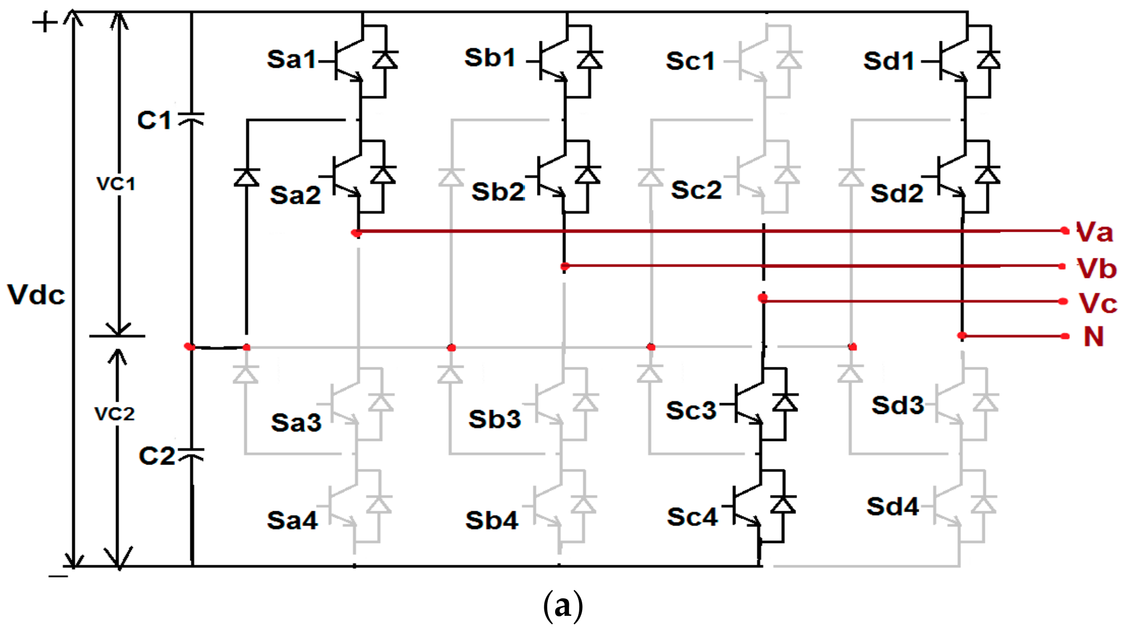
Figure 2 shows a diagram of a 3-phase 4-leg 3-level NPC inverter, which consists of two dc link capacitances (C1 and C2), four legs, each of which has four power switches and two clamping diodes. The proposed system has in total 81 switching states:
where n is the number of level of inverter, and 4, the number of legs. These 81 switching states includes zero, small, medium and large vectors with reduntant switching vectors. Generally 3-phase 4-leg 3-level NPC inverters can generate output voltages at three levels (0, . Similarly, by appling these possible combinations for all four legs in the inverter, it can be operated under 81 switching modes.
Figure 3 shows the modes of operation of the 3-phase 4-leg 3-level NPC inverter. Figure 3a shows the switching state of (PPNP) operation, where the switches in Leg1-Sa2, Sa2, in Leg2-Sb1, Sb2, in Leg3-Sc3, Sc4, in Leg4-Sd1, Sd2 are in ON condition. Similarly the Figure 3b shows the switching state of (ONPN) operation, where the switches in Leg1-Sa3, Sa4, in Leg2-Sb3, Sb4, in Leg3-Sc1, Sc2, in Leg4-Sd3, Sd4 are in ON condition.
2.2. Voltage and Current Control Loop of Proposed System
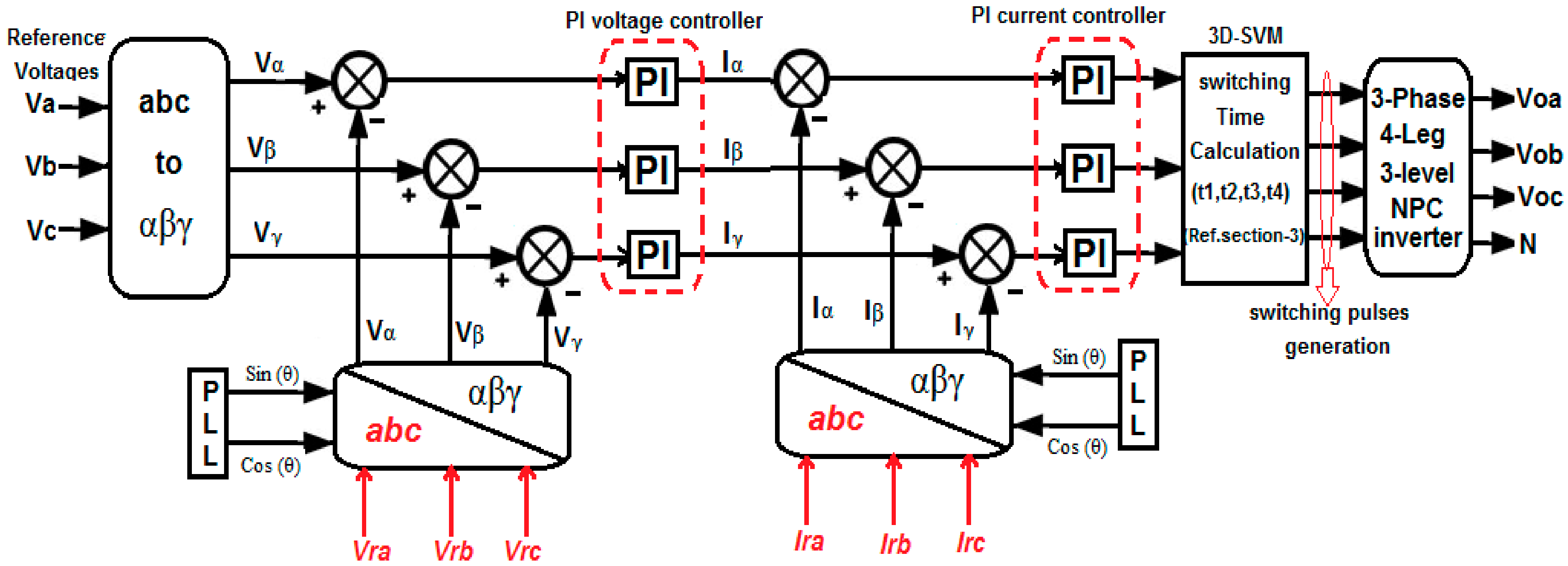
Figure 4 shows the block diagram for current and voltage control loop in the system. The 3-phase input voltage (Va, Vb, Vc) is converted to reference voltages (Vα, Vβ, Vγ) using the Equation (2),
Through the PLL, the unit vectors cos θ and sin θ are calcuated, which is used to obtained the voltage interms of α-β-γ. To convert α-β-γ to again a-b-c co-ordinate system, Equation (3) is used,
The voltages (Vα, Vβ, Vγ) are obtained from the 3-phase rectifier and compared with voltage obtained from references voltages. Then the voltage error is changed to current error (Iα, Iβ, Iγ) by PI controller, which is compared with reference current parameters obtained from the abc to α-β-γ conversion.
The current error is again tuned by the PI current controller to convert again into voltage, which is considered as reference voltage to active switching vectors using 3D-SVM method. The switching times are calculated to control the proposed 3-phase 4-leg 3-level NPC inverter.
3. Effectual 3D-SVM for 3-Phase 4-Leg 3-Level NPC Inverter
The advantages of the effectual 3D-SVM method over conventional 3D-SVM are the redundancy in switching states present in the 3D cubic space plane. Each vertex point has one, two or three switching states, so the switching time calculation is based on the selection of possible vectors in the cubic area. The mathematical calculation becomes simple and hence no need for transformations and angle determinations. The structure of 3D-cubic space plane is shown in Figure 5.
In order to maintain the constant voltage across the dc link capacitors, the load current must be controlled. Each leg can generate different load current combinations, where each switching vector combination unbalances the voltage across the dc link capacitors, but in our effectual 3D-SVM scheme, α-β-γ coordinate has redundant switching combinations. In conventional 3D-SVM, the 3D cubic plane for 3-level 3-leg NPC inverter has 27 switching vectors placed in 27 vertex points, which has harder switching due to non-redundant switching vectors. But the 3D-SVM cubic structure with α-β-γ coordinate system has totally 81 switching vectors with 65 vertex points. Among them 14 are redundant switching vectors, 50 are non-redundant switching vectors and the remaining one is a zero vector.
3.1. Reference Vector Synthesis
The effectual 3D-SVM technique simply calculates the four switching state voltage vectors which produce the reference vector. In general, for unbalanced system or with triple harmonics or 4-leg inverter, the reference vector could not be located in the 2D plane (hexagonal plane) of the multilevel inverter. Since it is necessary to use a switching sequence with four active state switching vectors. Thus, the reference vector points to a volume which is a prism in the 3D plane. The vertices of those prisms are the active state voltage vectors of the switching sequence. In addition, the effectual 3D-SVM algorithm authorizes to acquire the subsequent duty cycles without using any look up tables or mathematical functions.
The input of effectual 3D-SVM modulated technique is the normalized reference voltage vector. The normalized vectors used in the system only depends on level of the inverter system and DC-link capacitor’s voltage level. In the proposed 3D-SVM, the reference voltage vector is decomposed into two components as:
V0—output voltage, Vat—three level voltages.
In a-b-c coordinates, it is expressed as:
The output voltage component of the reference voltage vector is defined as:
The reference vector voltage is abridgment of the output voltage and the three level inverter voltage as in Equation (5). The three level components is defined as:
3.2. Tracking of Subcubes and Prisms
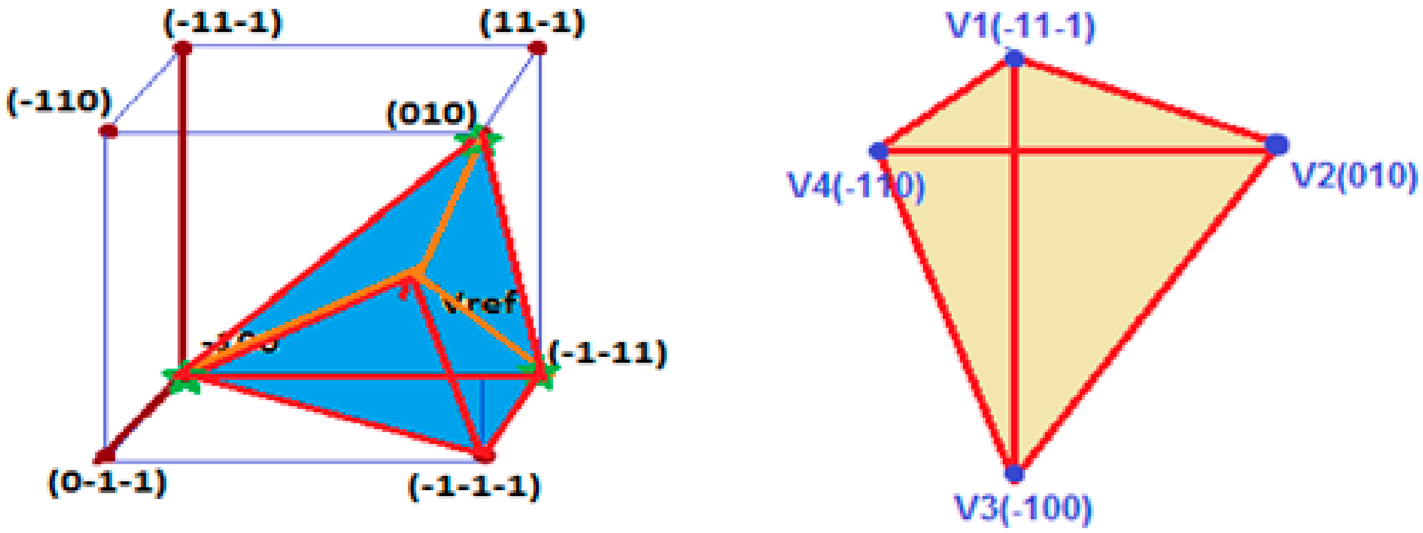
To identify the reference vectors in 3D-cubic space plane, the subcubes and prisms are to be tracked. This space can be decomposed into several subcubes and prisms which generate the cube’s total volume, which is shown in Figure 6. The reference vector in three-phase coordinates are assumed as (Xa, Xb, Xc), the integer component of each vector is (a, b, c).
Initially 3D space plane is covered by a number of subcubes depending on the number of the levels of the inverter. The 3-phase 4-leg, n-level inverter has (n − 1)4 subcubes, and the proposed system has (3 − 1)4 = 16 subcubes. The flowchart for identification of subcubes in 3D-cubic space plane is shown in Figure 7.
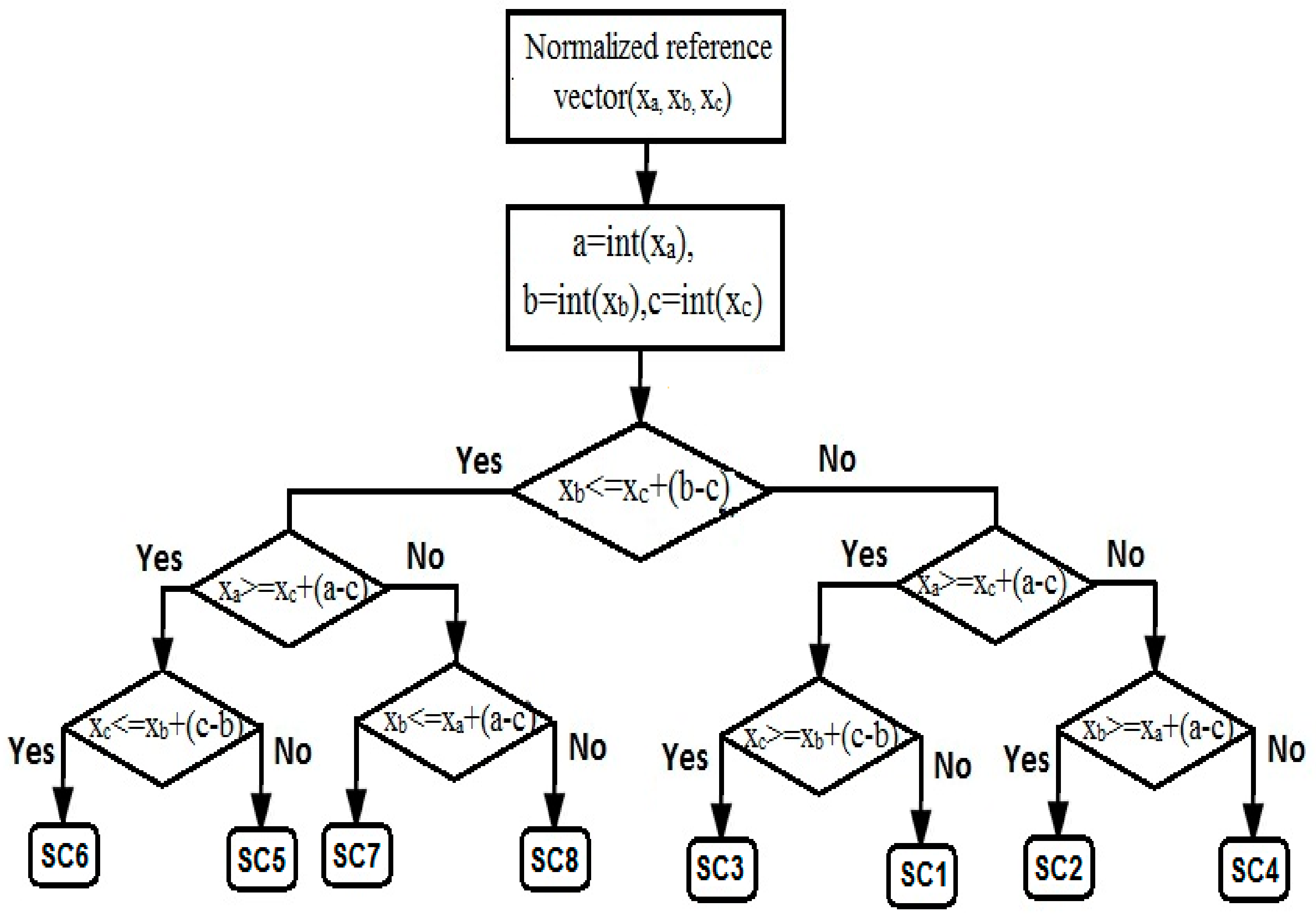
The prisms in the various subcubes are to be identified accurately to track the reference vector. The proposed system has 6 prisms in each subcube, so totally 96 prisms are located in the 3D cubic plane. The prisms location in various subcubes using normalised reference vectors in three-phase coordinates are assumed as (Ua, Ub, Uc) and the integer component of each vector is (a, b, c). The Figure 8 shows the flowchart for tracking of prisms in various subcubes.
After finding the original reference (α-β-γ) coordinates the corresponding switching pulses can be generated to control the proposed 4-leg NPC inverter. Then the reference vector is normalized by Vdc/2, which is expressed as
where is the original reference vector, is the normalized reference vector to track the various subcubes and prisms in 3D-cubic space plane.
3.3. Calculation of Switching Times
Switching times are mainly calculated from reference vectors, which are tracked by the identification of the various subcubes and prisms in the 3D-cubic space plane. The switching times for the proposed 3-phase 4-leg 3-level NPC inverter are calculated with redundant switching vectors. From that, the active vector selection is done with minimised switching and computational time.
In effectual 3D-SVPWM scheme, the total switching time calculation for 3-phase 4-leg 3-level inverter system calculated from prism tracking in a subcube is shown in Figure 9. The switching times of each prism placed in a 3D-cubic space plane is written as:
where are the three level voltage components calculated from Equation (7). With the help of the Equations (9)–(13) the switching pulses of proposed 3-phase 4-leg NPC inverter are calculated.
4. Simulation Results and Discussions
The proposed Unified Power Quality Conditioner using 3-phase 4-leg 3-level NPC inverter with 3D-SVM control is designed and tested in Simulation and Hardware. The parameter given in Table 1 is used for both simulation and hardware.
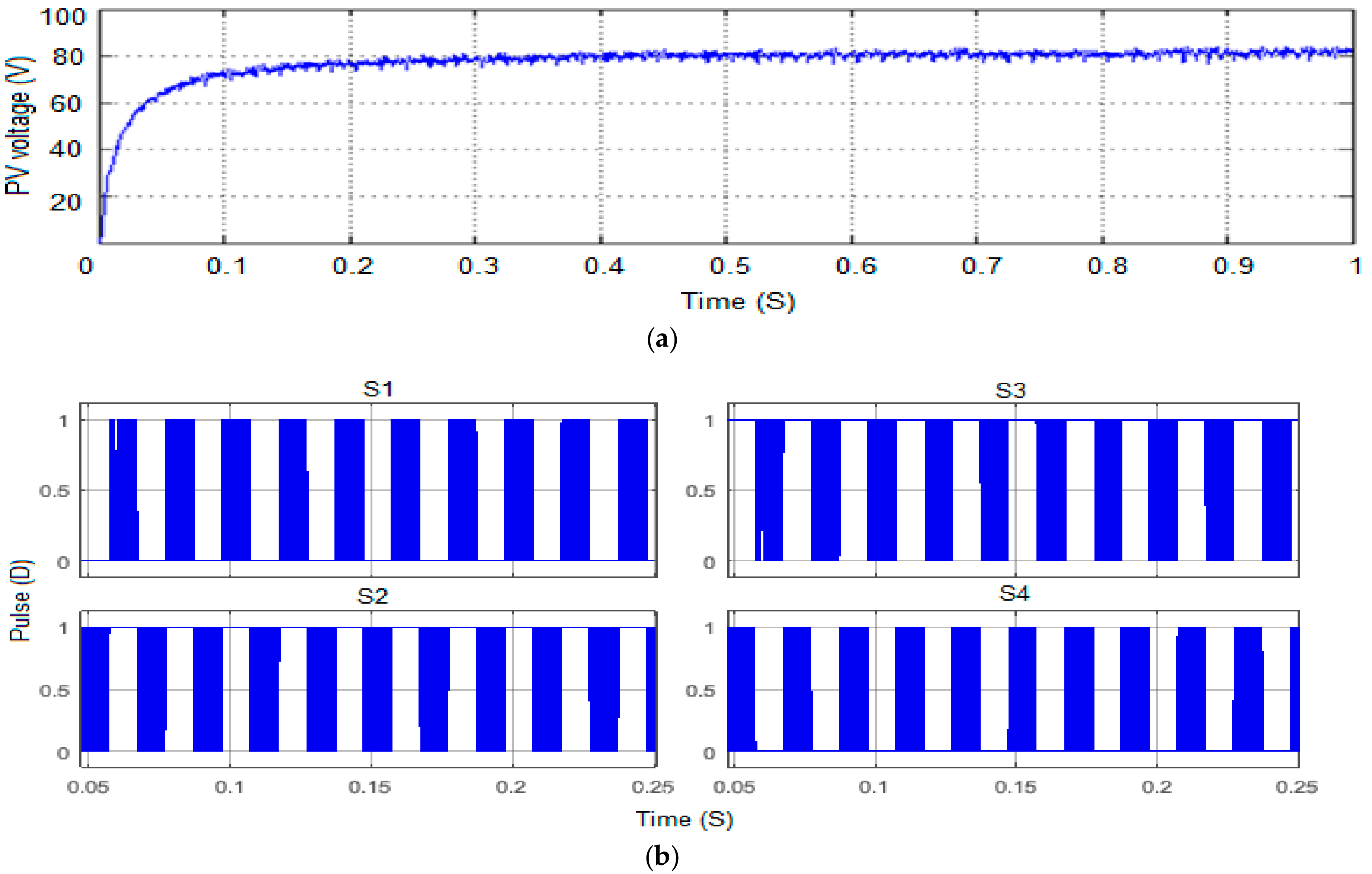
Figure 10a,b show the PV array voltage and switching pulses for leg-A of 3-level NPC inverter respectively. The comparison of various parameters like stepped inverter output voltage, output voltage with split inductor, capacitor voltage balancing and output current for various control methods like 2D-SVM, 3D-SVM and effectual 3D-SVM is shown in Figure 11. From the comparison, it is evident that the effectual 3D-SVM is better than other control schemes.
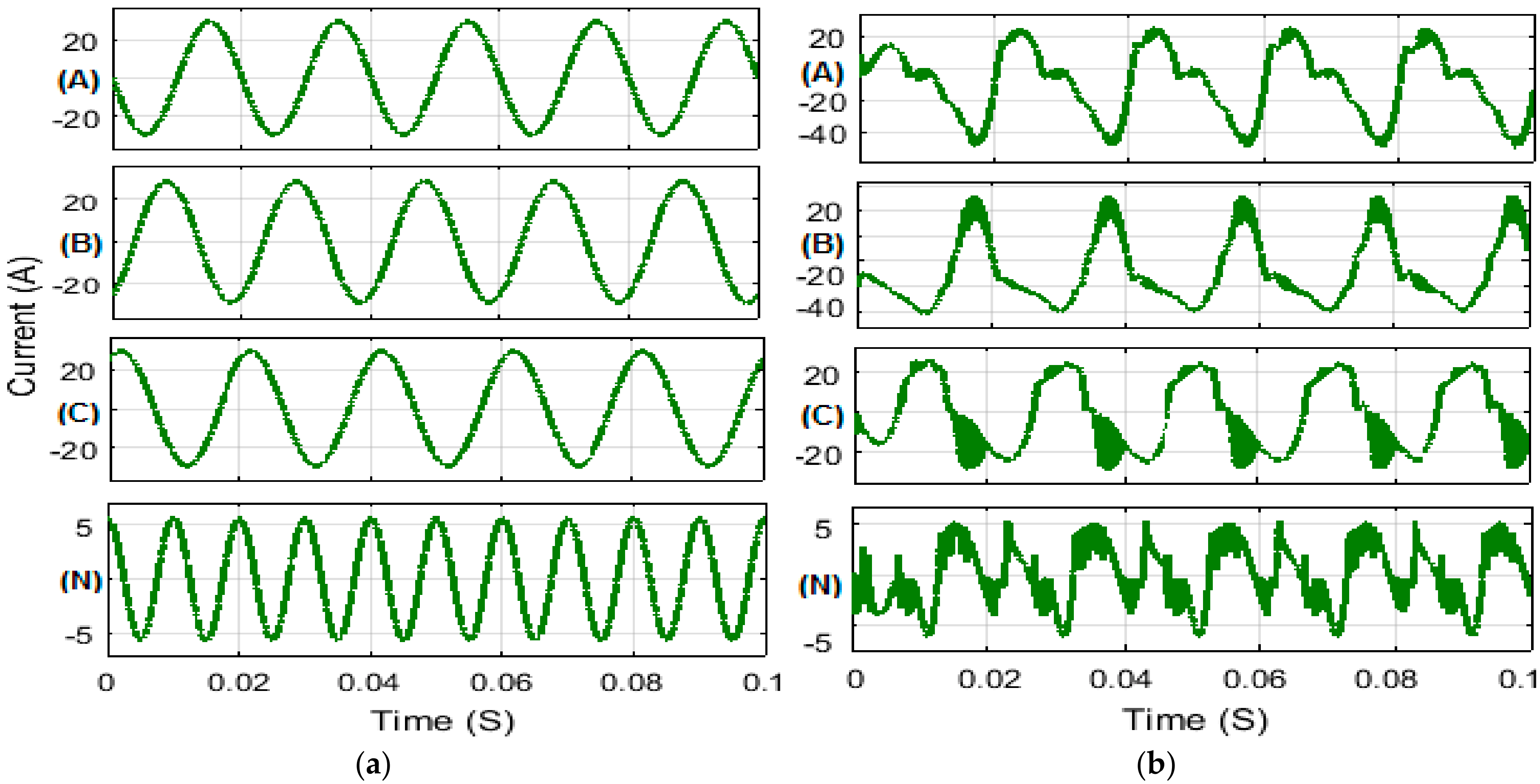
Figure 12 shows the 4-leg inverter output current with split inductor for different load under balanced and unbalanced conditions with effectual 3D-SVM scheme. In that effectual 3D-SVM provides better results for both balanced and unbalanced load compared with other control strategies. Figure 13 shows the proposed system with unbalanced load condition, in that Figure 13a,b shows the output current with and without controller to the utility grid, and Figure 13c shows the neutral current. The output current for 3-leg and 4-leg inverter shown in Figure 14a,b shows the comparison of output current for 3D-SVM and 2D-SVM control.
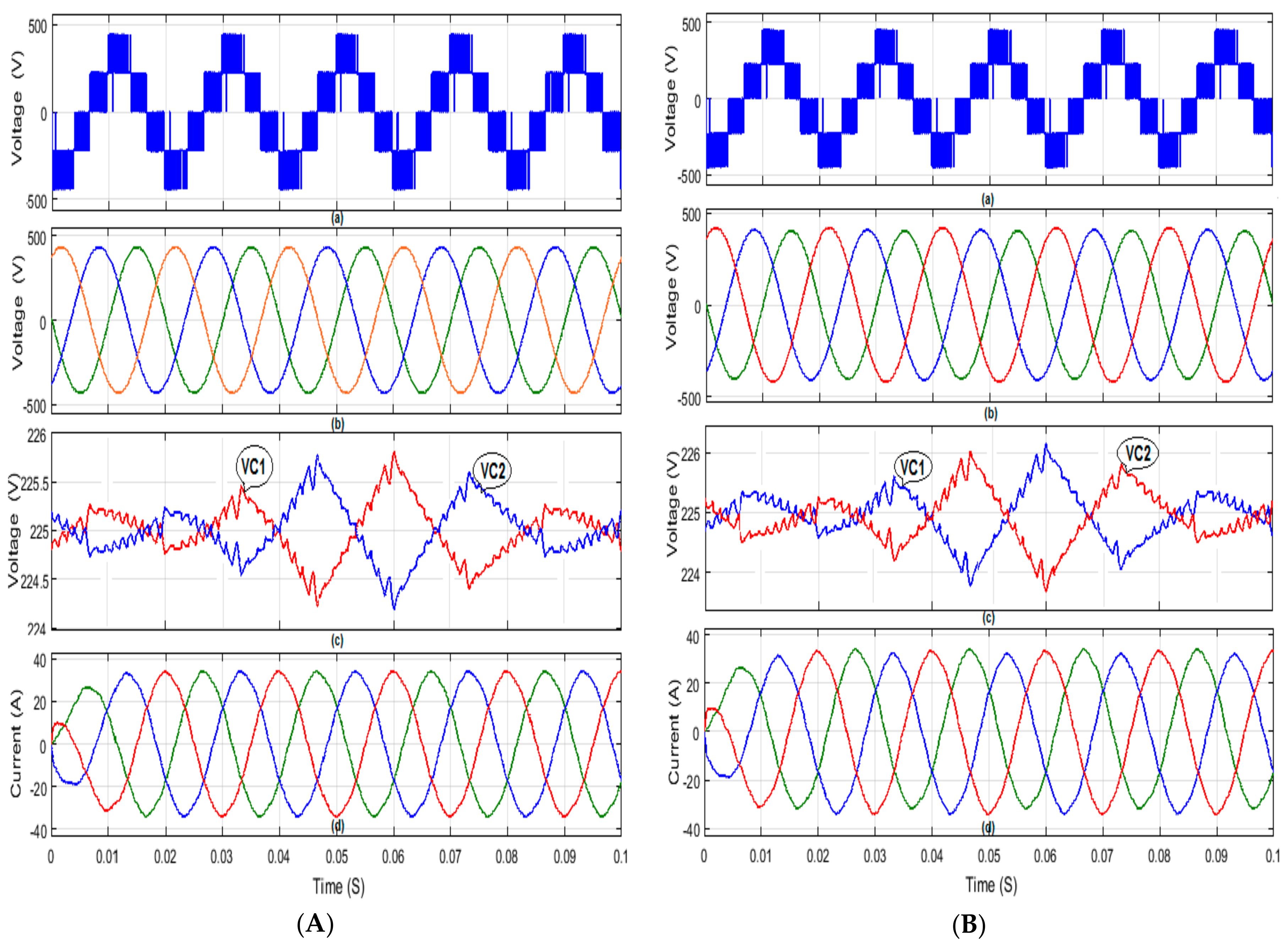
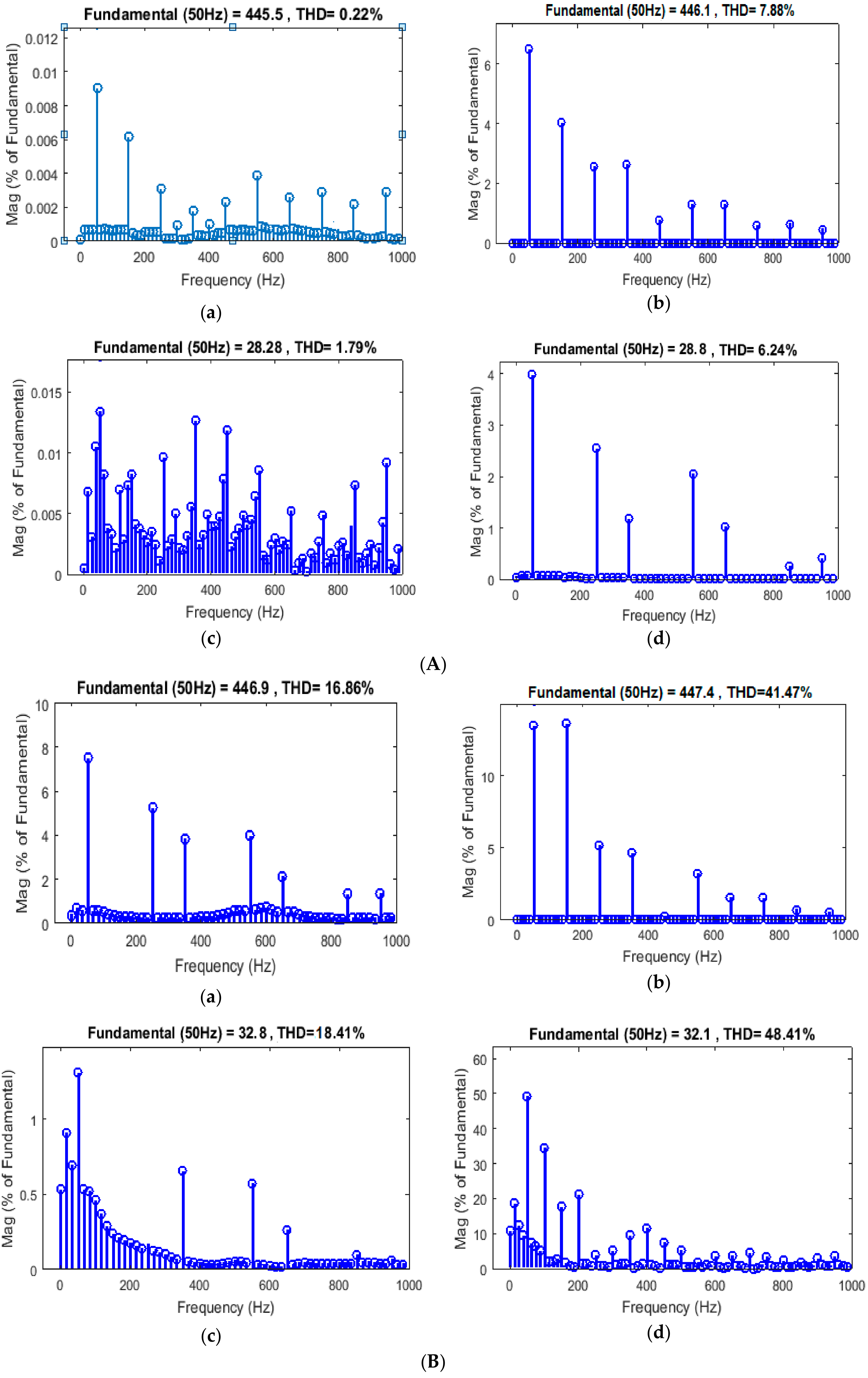
The THD analysis of proposed 3-phase 4-leg 3-level NPC inverter system under balanced and unbalanced conditions analysed for output voltage and current with effectual 3D-SVM and 2D-SVM is shown in Figure 15. From the analysis, the proposed effectual 3D-SVM control for balanced load it has THD of 0.22% and 1.79% for output voltage and current respectively and for the unbalanced load has THD of 7.88% and 6.24% for output voltage and current respectively. From the figure it is evident that the 4-leg inverter with effectual 3D-SVM has better performance when compared to other controls.
Figure 16 shows the comparison of THD and capacitor voltage balancing for various NPC inverter systems and control methods under balanced and unbalanced condition. Among that effectual 3D-SVM with 4-leg inverter provides enhanced performance, for capacitor voltage balancing of 1.2% and 4.8% for balanced and unbalanced load respectively.
5. Experimental Results and Discussion
To demonstrate the simulation results of the proposed 3-phase 4-leg 3-level NPC inverter system, the experimental setup was developed and tested. The experimental setup of the proposed system is shown in Figure 17, which has the various components like equivalent dc-link capacitance of 100 µF, split inductor of 4 mH, 16-IGBT power switches in 4-leg NPC inverter, FPGA controller programmed with VHDL coding using Xilinx-ISE, a Digital Storage Oscilloscope and 3-phase load system. The dc voltage generated from the PV system is added with rectified voltage using 3-phase rectifier, which is supplied to 3-phase 4-leg 3-level NPC inverter. The inverter injects the output current into utility grid system to improve the quality of power and minimise the neutral current. Figure 18a shows the switching pulse generation using effectual 3D-SVM control and Figure 18b shows inverter stepped output voltage with 450 V. Figure 18c shows the capacitor voltage balancing of the proposed 3-phase 4-leg NPC inverter, which is balanced up to 1.24%.
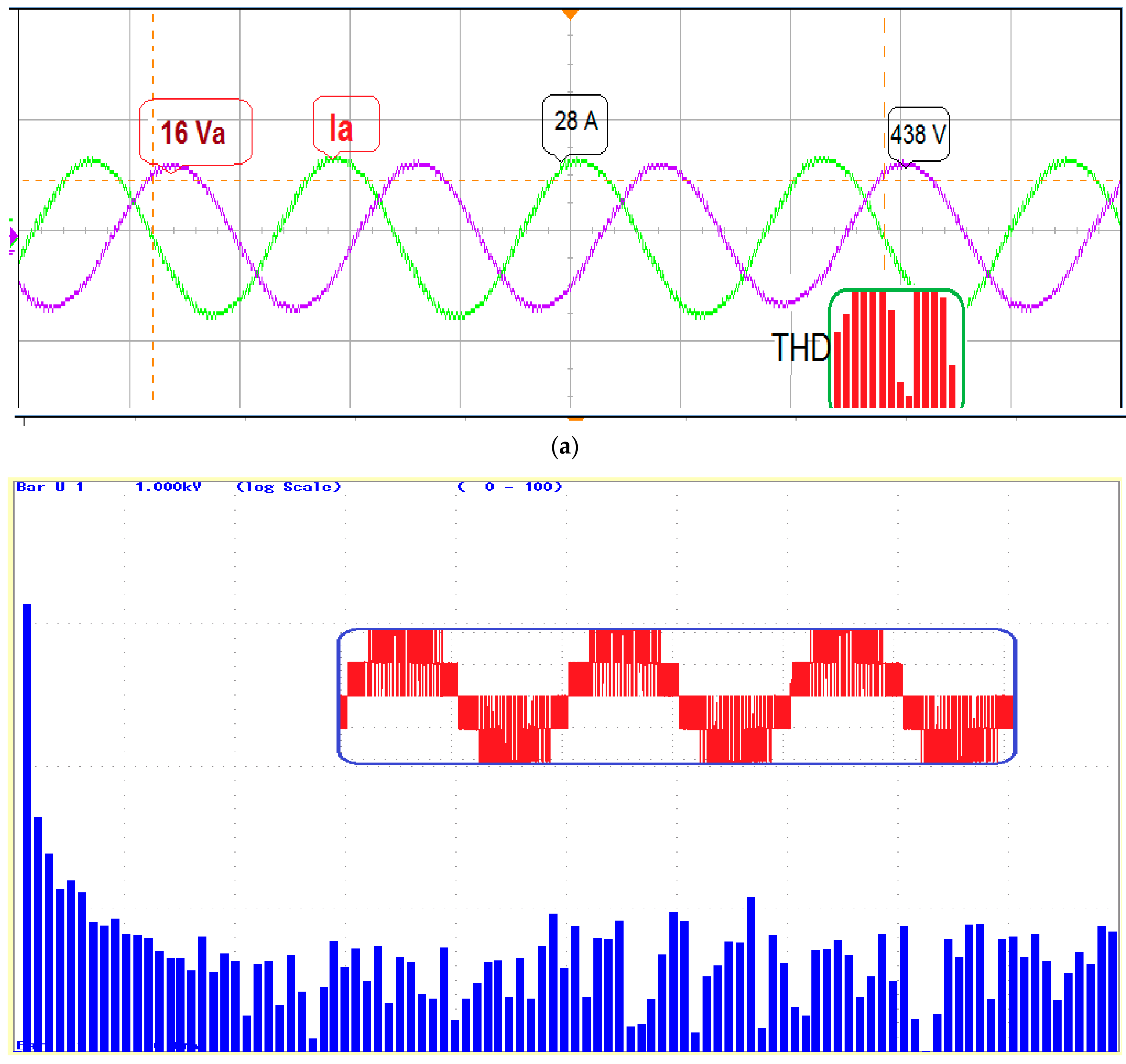
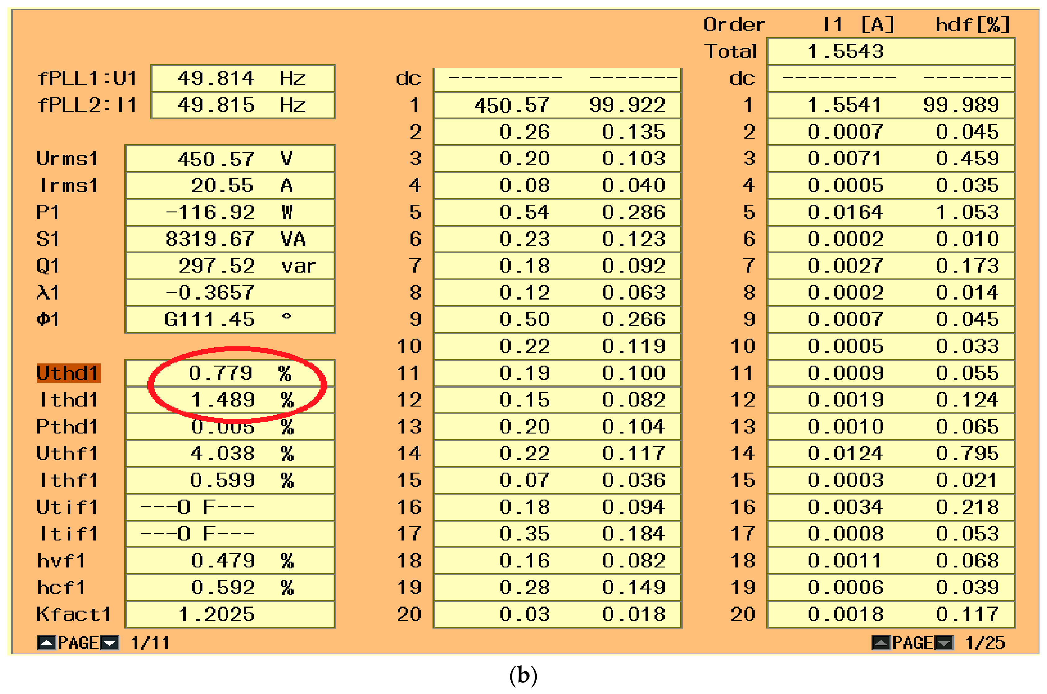
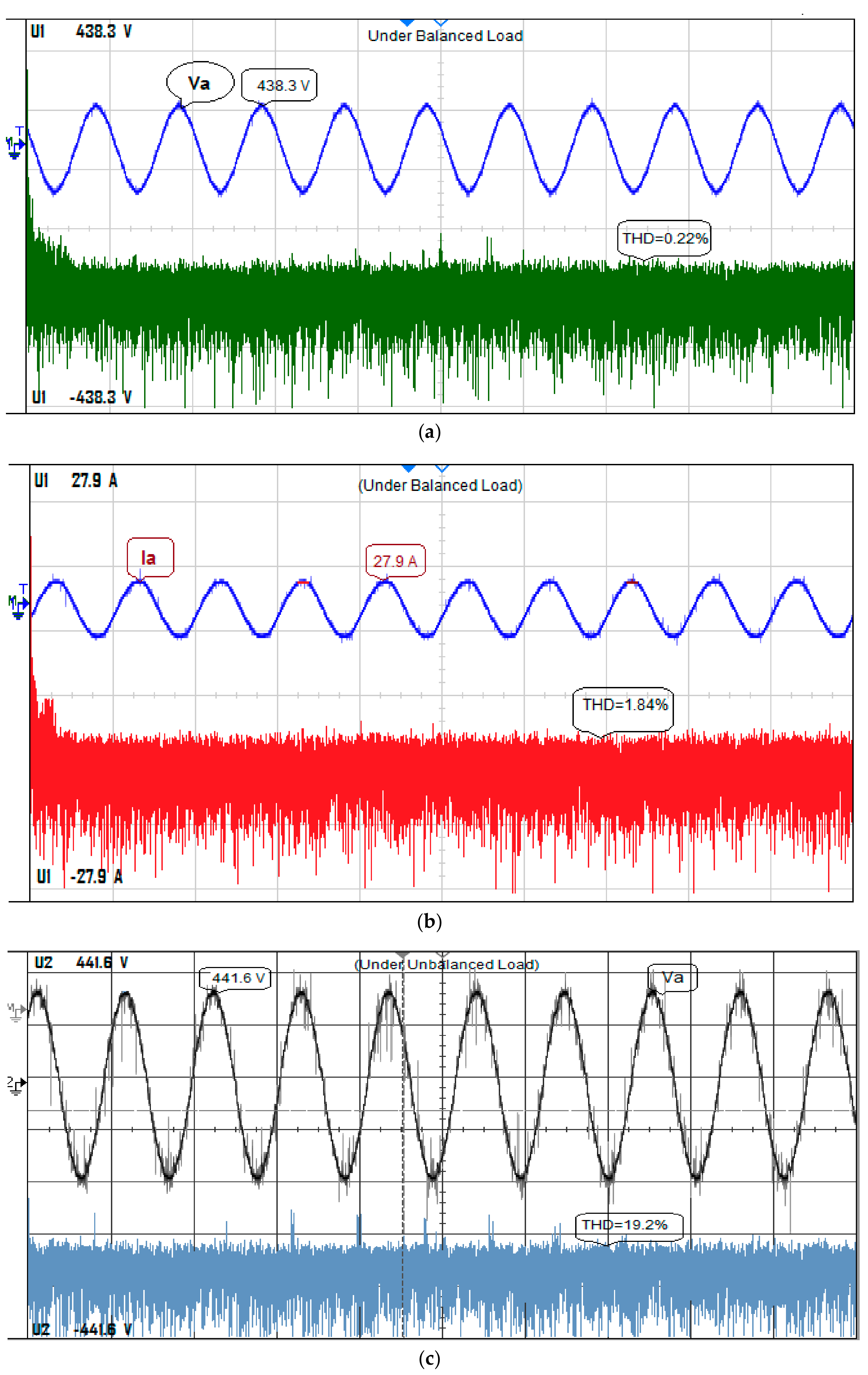
The NPC inverter output voltage and current with split inductor for balanced and unbalanced load is shown in Figure 19. Figure 19a,b show the phase-A output voltage and current for balanced load, respectively, Similarly, Figure 19c,d show the phase-A output voltage and current for unbalanced load, respectively. Figure 20 shows the comparison of output voltage and current in phase-A and the THD analysis of stepped inverter output voltage.
6. Conclusions
In this paper, an effectual 3D-SVM control method is implemented for 3-phase 4-leg 3-level NPC inverters to balance dc-link capacitor voltage and minimise voltage stress in addition to improve the power quality issues. This control method is operated with a natural α-β-γ coordinate system and the NPC inverter acts as an active filter to remove the harmonic content present in the output and hence to improve the power quality of the system. The dc link capacitor voltage is balanced by utilising the active switching vectors from only non-redundant switching states. The total harmonic distortion of the proposed system is better when compared to other conventional PWM methods. The following are the essential features of the proposed system:
- ✓
- The dc-link capacitor voltage is balanced up to 1.2%.
- ✓
- The voltage and current THD of the proposed system is 0.22% and 1.79%, respectively, for balanced load and 7.88% and 6.24%, respectively, for unbalanced load.
- ✓
- Effectual 3D-SVM is better control method for 3-phase 4-leg 3-level NPC inverter, when compared to other methods reported in this paper.
Author Contributions
Palanisamy Ramasamy formulated the problem, obtained the solution, performed the experiments and wrote the paper; Vijayakumar Krishnasamy verified the results with other control methods and proof checked the paper.
Conflicts of Interest
The authors declare no conflict of interest.
References
- Tolbert, L.M.; Peng, F.Z. Multilevel converters as a utility interface for renewable energy systems. In Proceedings of the IEEE PES Summer Meeting, Seattle, WA, USA, 16–20 July 2000. [Google Scholar]
- Aredes, M.; Hafner, J.; Heumann, K. Three-Phase four-wire shunt active filter control strategies. IEEE Trans. Power Electron. Soc. 1997, 12, 311–318. [Google Scholar] [CrossRef]
- Gupta, A.K.; Khambadkone, A.M. A Space Vector PWM Scheme for Multilevel Inverters Based on Two-Level Space Vector PWM. IEEE Trans. Ind. Electron. 2012, 53, 1631–1639. [Google Scholar] [CrossRef]
- López, Ó.; Alvarez, J.; Doval-Gandoy, J.; Freijedo, F.D. Multilevel multiphase space vector PWM algorithm. IEEE Trans. Ind. Electron. 2008, 55, 1933–1942. [Google Scholar] [CrossRef]
- Modesto, R.A.; da Silva, S.A.O.; de Oliveira Júnior, A.A. Power quality improvement using a dual unified power quality conditioner/uninterruptible power supply in three-phase four-wire systems. IET Power Electron. 2015, 8, 1595–1605. [Google Scholar] [CrossRef]
- Verdelho, P.; Marques, G.D. Four-wire current-regulated PWM voltage inverter. IEEE Trans. Ind. Electron. 1998, 45, 761–770. [Google Scholar] [CrossRef]
- Yuan, X.; Orglmeister, G.; Merk, W. Managing the DC link neutral potential of the three-phase-four-wire neutral-point-clamped (NPC) inverter in FACTS application. In Proceedings of the Iecon ′99 Proceedings. The 25th Annual Conference of the IEEE Industrial Electronics Society, San Jose, CA, USA, 29 November–3 December 1999; pp. 571–576. [Google Scholar]
- Ojo, O.; Kshirsagar, P.M. Concise modulation strategies for four-leg voltage source inverters. IEEE Trans. Power Electron. 2004, 19, 46–53. [Google Scholar] [CrossRef]
- Mienski, R.; Pawelek, R.; Wasiak, I. Shunt compensation for power quality improvement using a STATCOM controller: Modelling and simulation. IEEE Proc. Gener. Transm. Distrib. 2004, 151, 274–280. [Google Scholar] [CrossRef]
- Mittal, N.; Singh, B.; Singh, S.P.; Dixit, R.; Kumar, D. Multilevel inverters: A literature survey on topologies and control strategies. In Proceedings of the IEEE 2012 2nd International Conference on Power, Control and Embedded Systems, Allahabad, India, 17–19 December 2012; ISBN 978-1-4673-1049-9. [Google Scholar]
- Dai, N.Y.; Wong, M.C.; Han, Y.D. Controlling trilevel center-split power quality compensator by 3-dimensional space vector modulation. In Proceedings of the Fifth International Conference on Power Electronics and Drive Systems, PEDS 2003, Singapore, 17–20 November 2003. [Google Scholar]
- Rodriguez, J.; Lai, J.S.; Peng, F.Z. Multilevel inverters: A survey of topologies, controls and applications. IEEE Trans. Ind. Electron. 2013, 49, 724–738. [Google Scholar] [CrossRef]
- Prats, M.M.; Franquelo, L.G.; Portillo, R.; Leon, J.I.; Galvan, E.; Carrasco, J.M. A 3-D space vector modulation generalized algorithm for multilevel converters. IEEE Power Electron. Lett. 2003, 1, 110–114. [Google Scholar] [CrossRef]
- Zhang, R.; Prasad, V.H.; Boroyevich, D.; Lee, F.C. Three-Dimensional space vector modulation for four-leg voltage-source converters. IEEE Trans. Power Electron. 2002, 17, 314–326. [Google Scholar] [CrossRef]
- Wong, M.C.; Zhao, Z.Y.; Han, Y.D.; Zhao, L.B. Three-Dimensional pulse-width modulation technique in three-level power inverters for three-phase four-wired system. IEEE Trans. Power Electron. 2007, 16, 418–427. [Google Scholar] [CrossRef]
- Chu, C.C.; Chen, C.L. Robust maximum power point tracking method for photovoltaic cells: A sliding mode control approach. Sol. Energy 2009, 83, 1370–1378. [Google Scholar] [CrossRef]
- Gonzalez, R.; Gubia, E.; Lopez, J.; Marroyo, L. Transformerless single-phase multilevel-based photovoltaic inverter. IEEE Trans. Ind. Electron. 2008, 55, 2694–2702. [Google Scholar] [CrossRef]
- Korn, A.J.; Winkelnkemper, M.; Steimer, P.; Kolar, J.W. Capacitor voltage balancing in modular multilevel converters. In Proceedings of the 6th International Conference on Power Electronics, Machines and Drives (PEMD 2012), Bristol, UK, 27–29 March 2012. [Google Scholar]
- Qin, J.; Saeedifard, M. Reduced Switching-Frequency Voltage Balancing Strategies for Modular Multilevel HVDC Converters. IEEE Trans. Power Deliv. 2013, 28, 2403–2410. [Google Scholar] [CrossRef]
Figure 1.
Power structure of 3-phase 4-wire (leg) NPC inverter with PV-UPQC system.
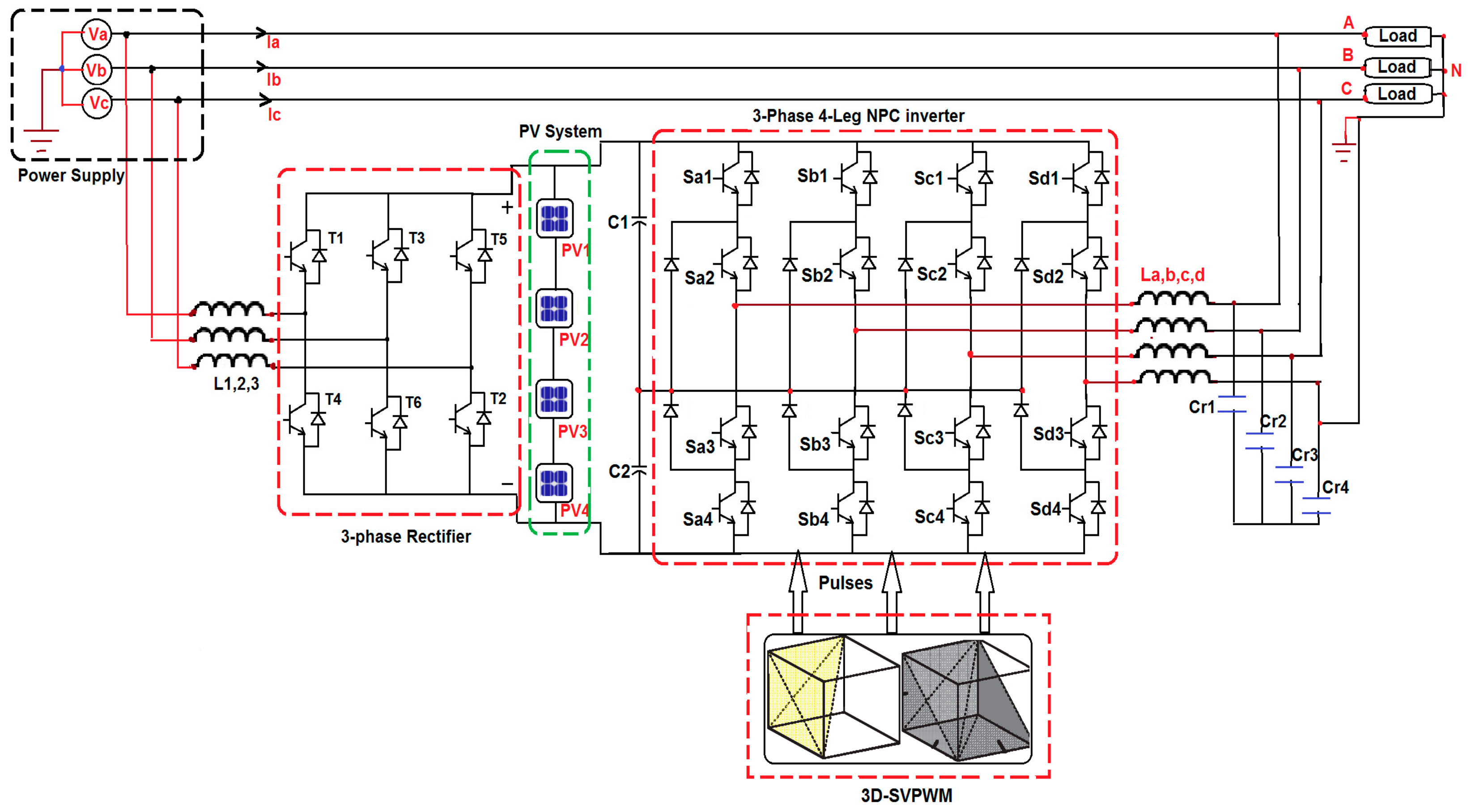
Figure 2.
Circuit of a 3-phase 4-leg 3-level NPC inverter.
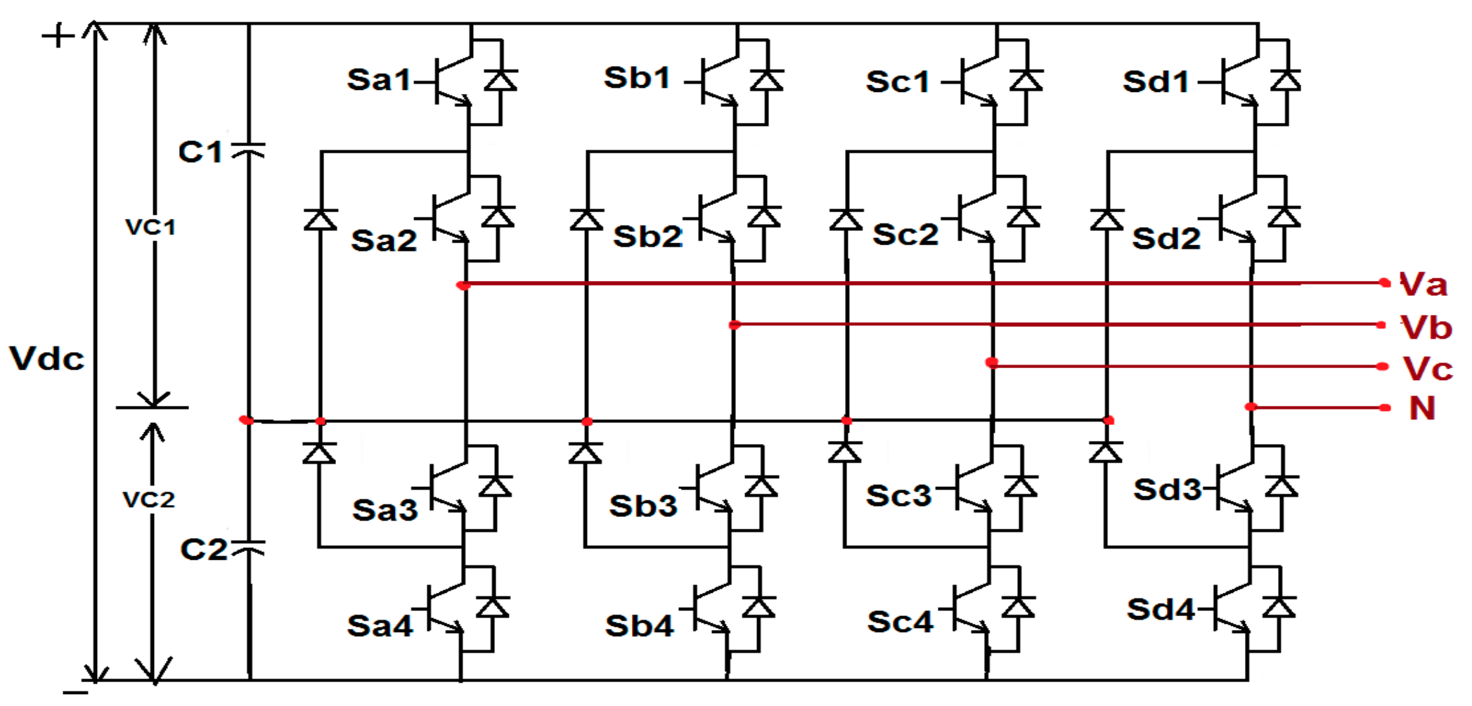
Figure 3.
Modes of operation of 3-phase 4-leg 3-level NPC inverter (a) PPNP; and (b) ONPN.

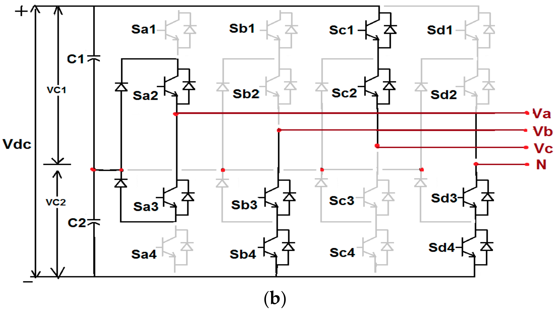
Figure 4.
Block diagram of the current and voltage control loop for proposed syetm.

Figure 5.
3D-SVM cubic structure with α-β-γ coordinate system.
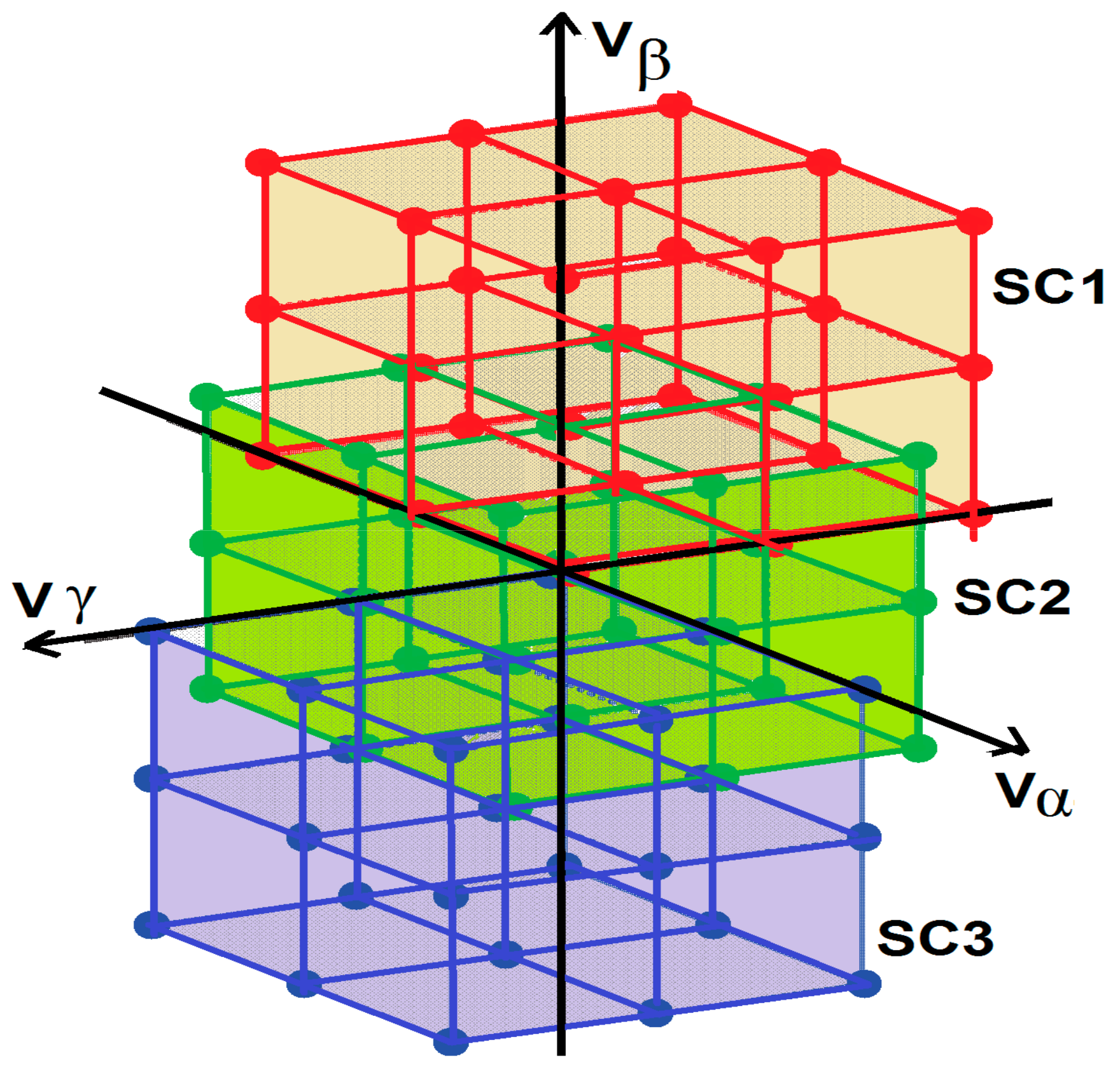
Figure 6.
Separation of subcubes with various Prisms.
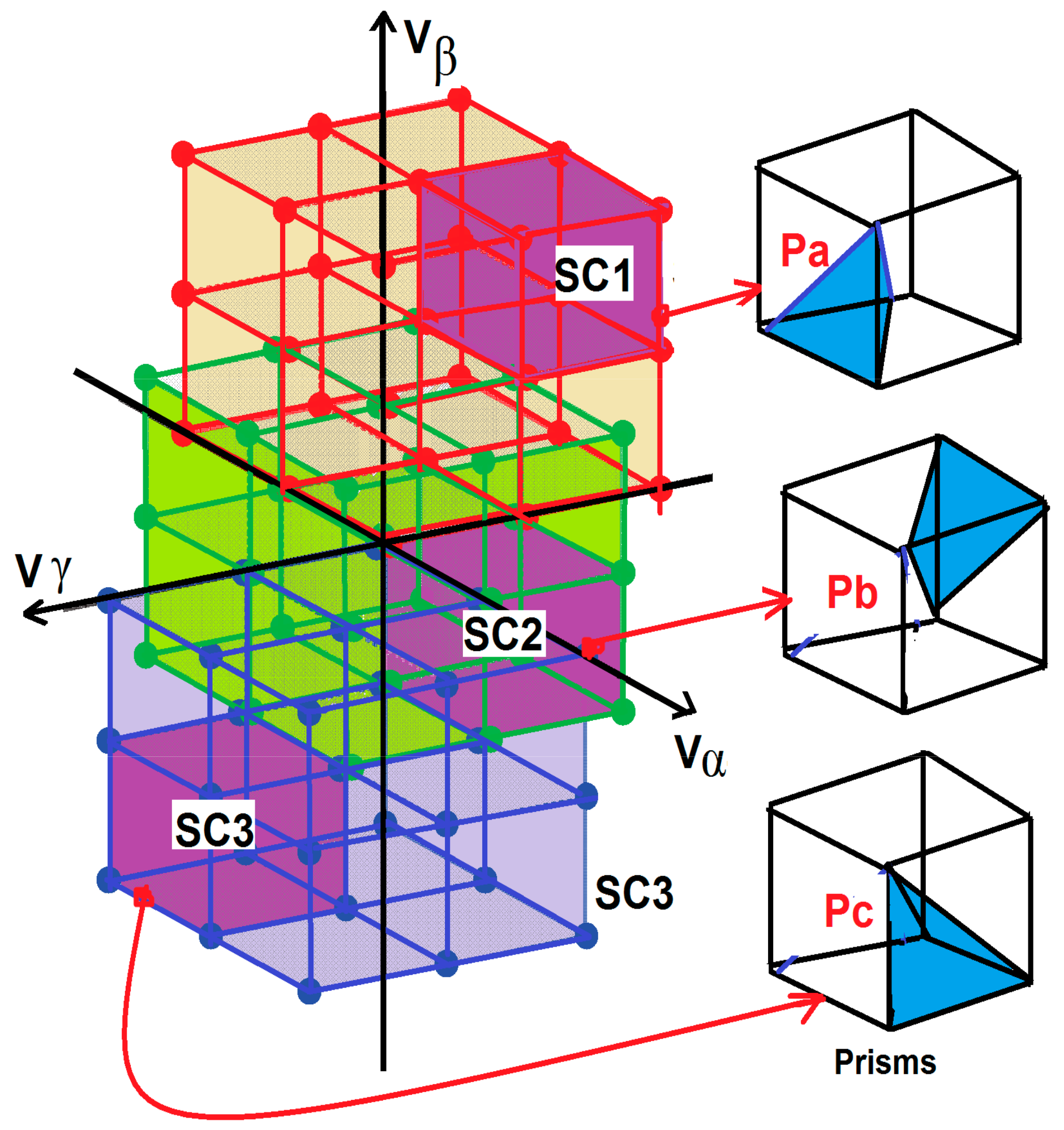
Figure 7.
Flowchart for tracking of subcubes.

Figure 8.
Flowchart for tracking of prisms.
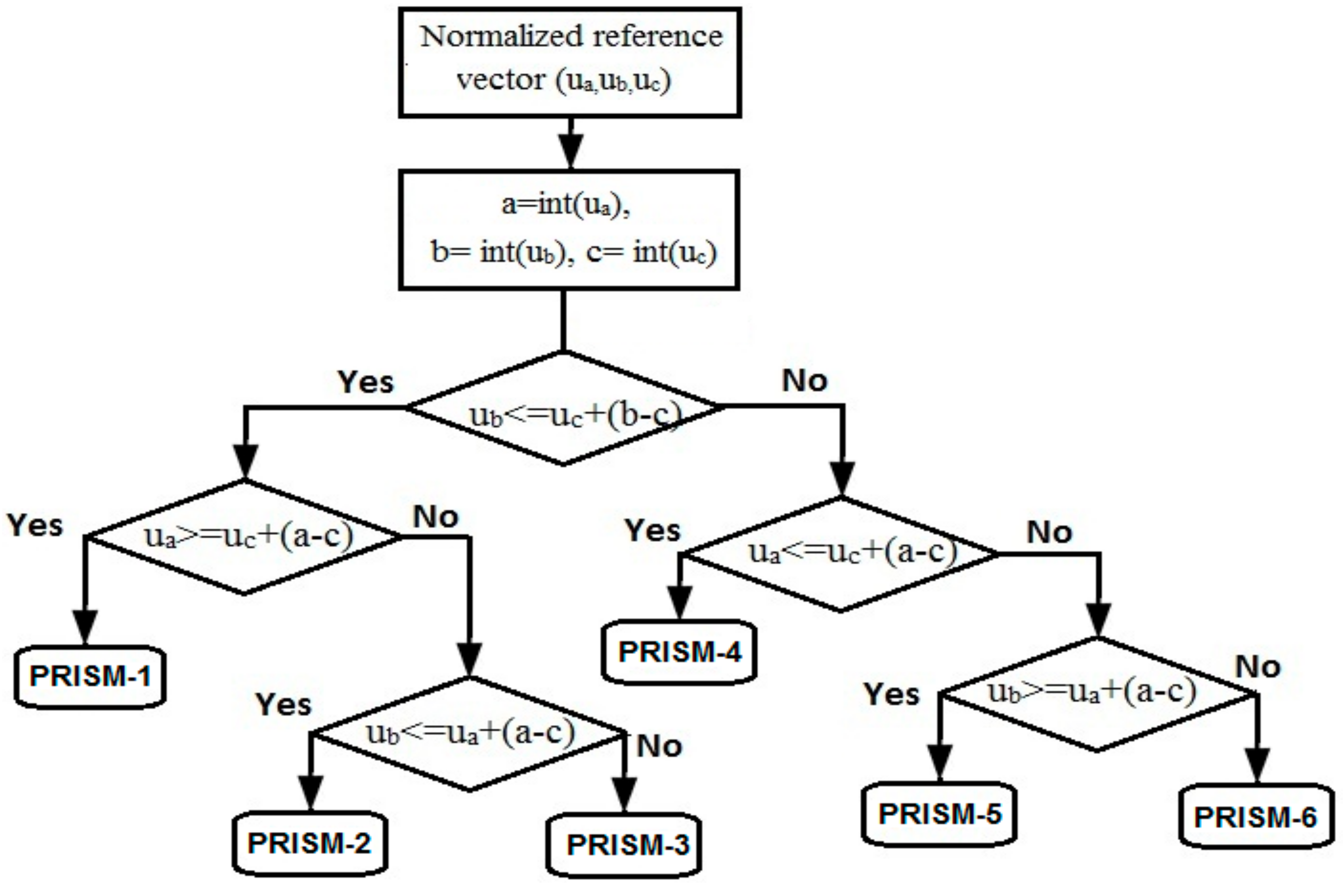
Figure 9.
Switching vector selection for Prisim1 located in subcube.

Figure 10.
(a) PV array voltage; and (b) switching pulses for leg-A of 3-level CI-NPC inverter.

Figure 11.
(A) 3-leg 3-level NPC inverter with 3D-SVM (B) 4-leg 3-level NPC inverter with 2D-SVM (C) 4-leg 3-level NPC inverter with effectual 3D-SVM, where (a) 3-level stepped inverter output voltage; (b) inverter output voltage with split inductor; (c) capacitor voltage balancing; and (d) inverter output current with split inductor.


Figure 12.
Inverter output current with split inductor for different load by effectual 3D-SVM scheme (a) 4-leg inverter current under balanced load; and (b) 4-leg inverter current under unbalanced load.
Figure 12.
Inverter output current with split inductor for different load by effectual 3D-SVM scheme (a) 4-leg inverter current under balanced load; and (b) 4-leg inverter current under unbalanced load.

Figure 13.
Proposed system with unbalanced load (a) output current; (b) injected current; and (c) neutral current.
Figure 13.
Proposed system with unbalanced load (a) output current; (b) injected current; and (c) neutral current.
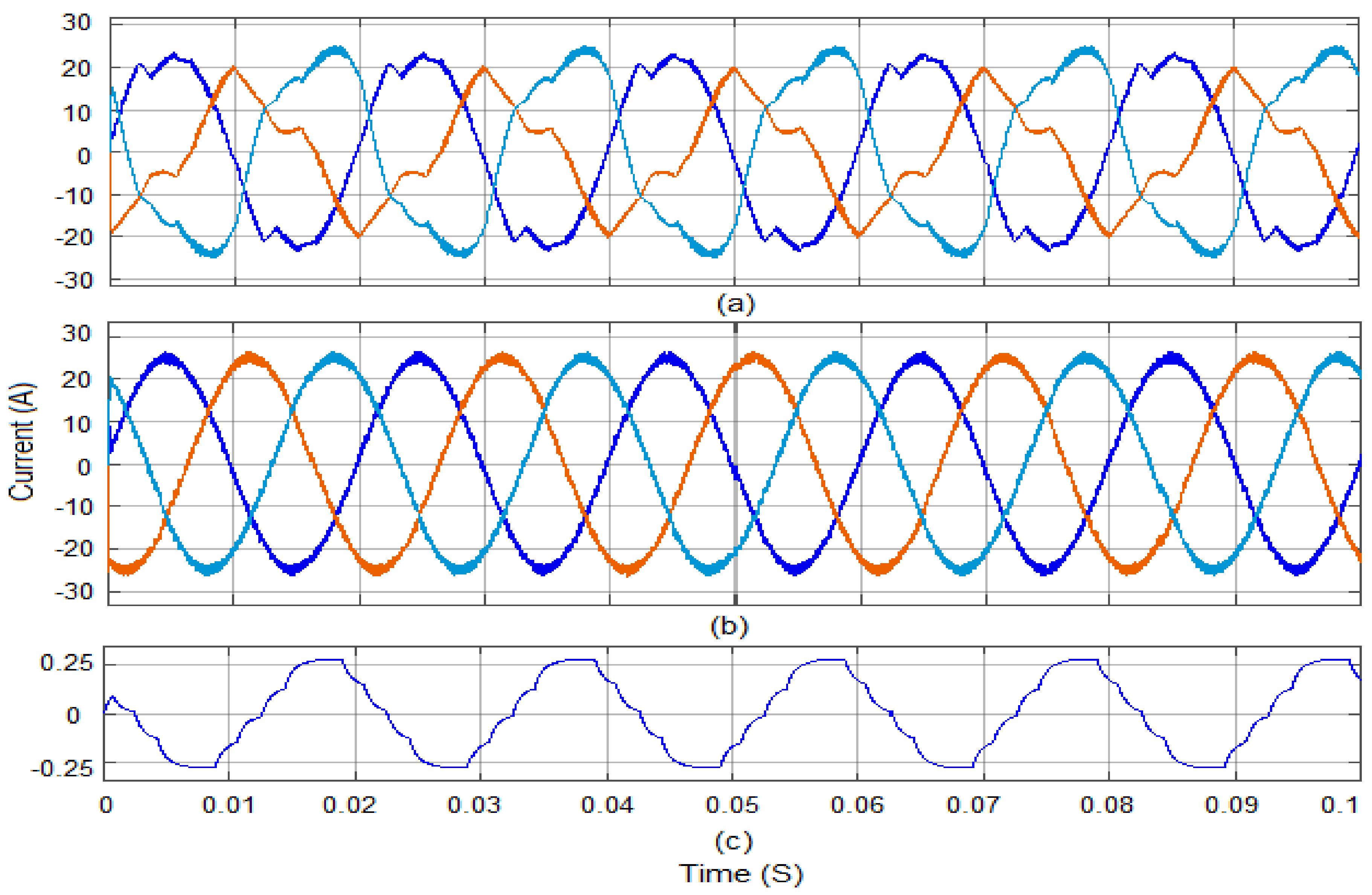
Figure 14.
Comparison of output current with various control schemes (a) 4-leg NPC inverter VS 3-leg NPC inverter using effectual 3D-SVM; and (b) 3D-SVM VS 2D-SVM for 4-leg NPC inverter.
Figure 14.
Comparison of output current with various control schemes (a) 4-leg NPC inverter VS 3-leg NPC inverter using effectual 3D-SVM; and (b) 3D-SVM VS 2D-SVM for 4-leg NPC inverter.
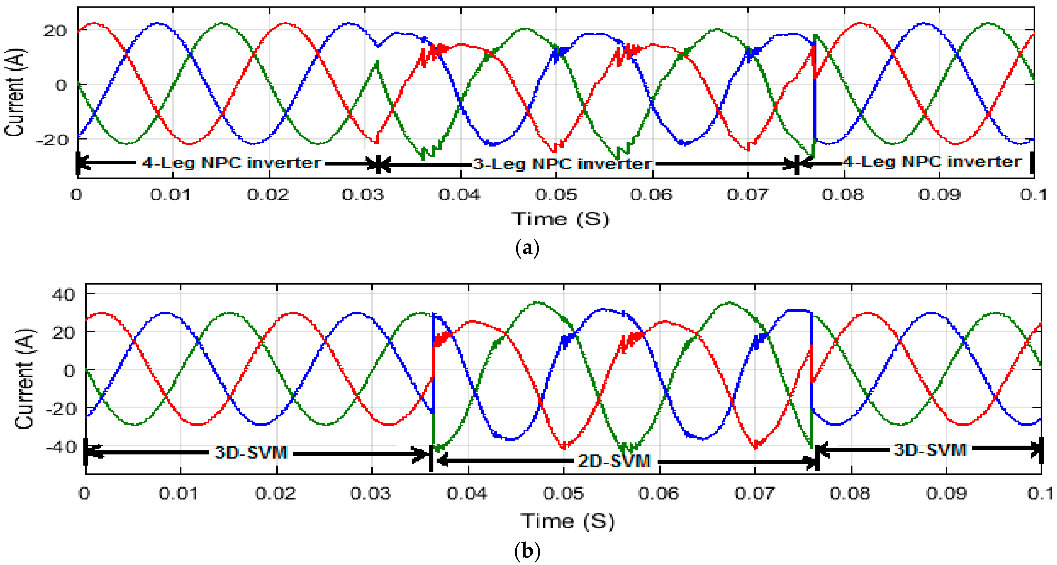
Figure 15.
THD analysis for 3-phase 4-leg NPC inverter (A) with balanced load; (B) with unbalanced load, where (a) output voltage with effectual 3D-SVM; (b) output voltage with 2D-SVM; (c) output current with effectual 3D-SVM; and (d) output current with 2D-SVM.
Figure 15.
THD analysis for 3-phase 4-leg NPC inverter (A) with balanced load; (B) with unbalanced load, where (a) output voltage with effectual 3D-SVM; (b) output voltage with 2D-SVM; (c) output current with effectual 3D-SVM; and (d) output current with 2D-SVM.

Figure 16.
Simulation results comparison for various scheme (a) THD analysis with balanced load; (b) THD analysis with unbalanced load; (c) capacitor voltage balancing for balanced load; and (d) capacitor voltage balancing for unbalanced load.
Figure 16.
Simulation results comparison for various scheme (a) THD analysis with balanced load; (b) THD analysis with unbalanced load; (c) capacitor voltage balancing for balanced load; and (d) capacitor voltage balancing for unbalanced load.
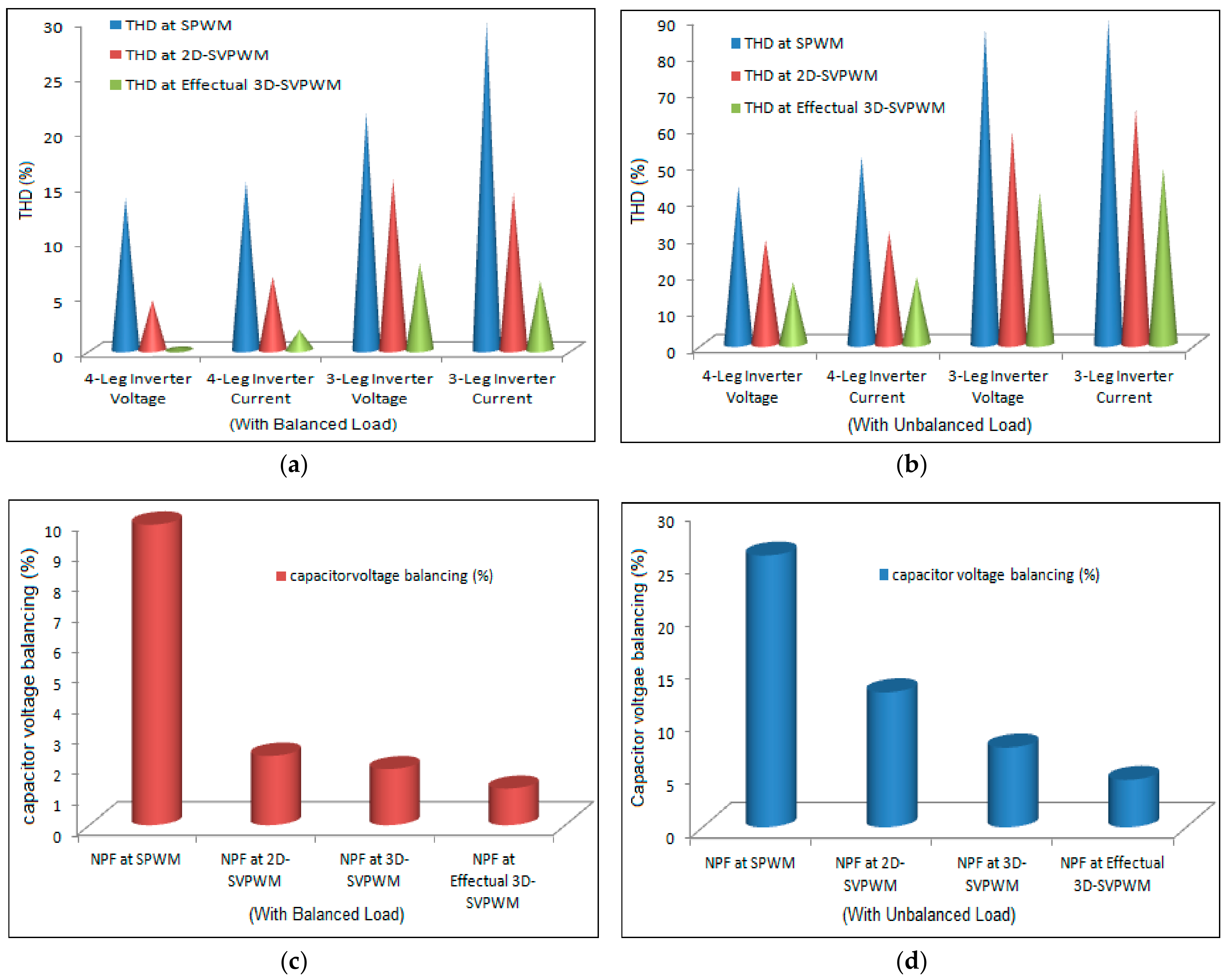
Figure 17.
Experimental setup of proposed system.
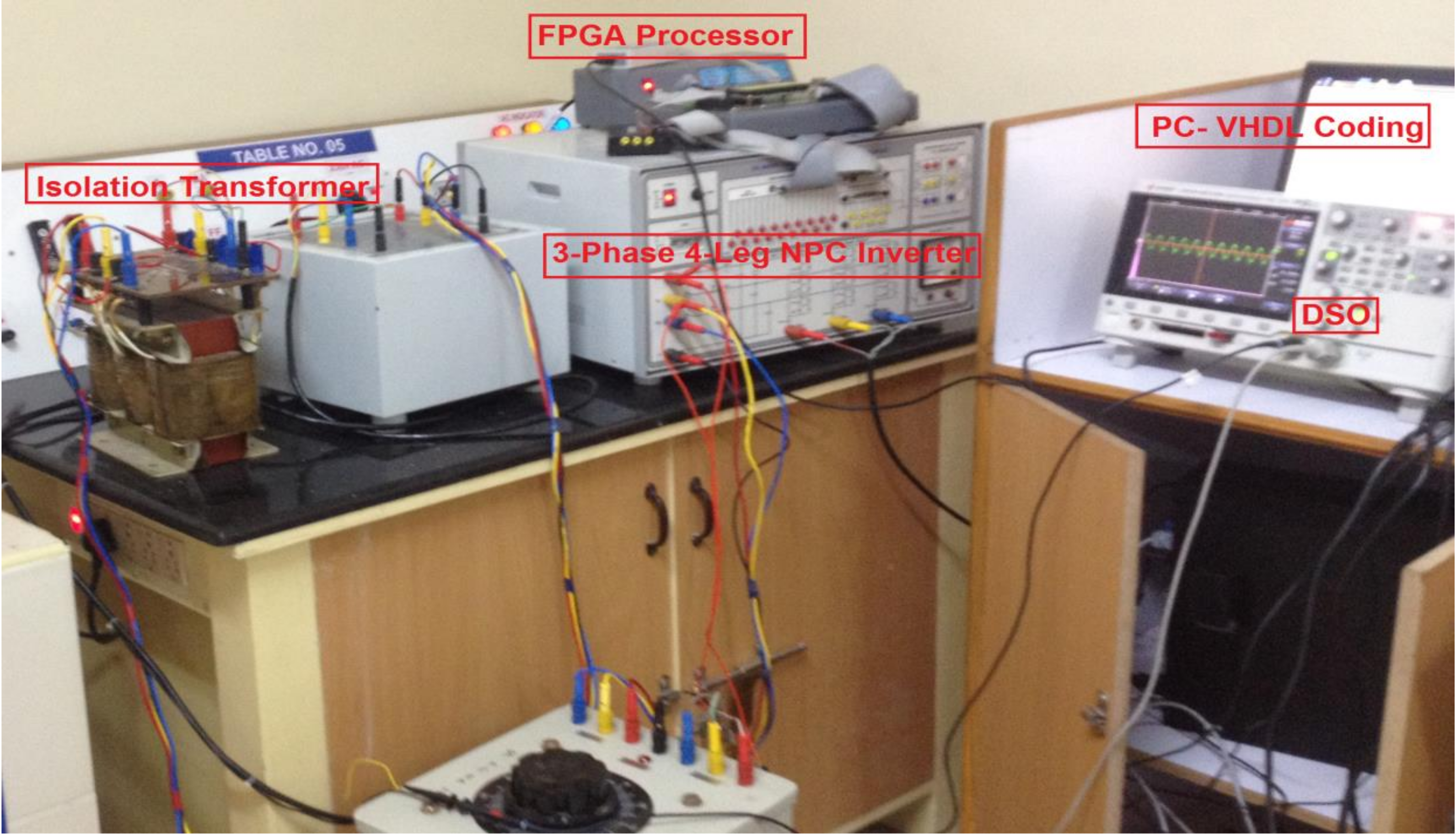
Figure 18.
Proposed 3-phase 4-leg NPC inverter with effectual 3D-SVM (a) switching pulses; (b) 3 level stepped inverter output voltage; and (c) capacitor balancing voltage.
Figure 18.
Proposed 3-phase 4-leg NPC inverter with effectual 3D-SVM (a) switching pulses; (b) 3 level stepped inverter output voltage; and (c) capacitor balancing voltage.
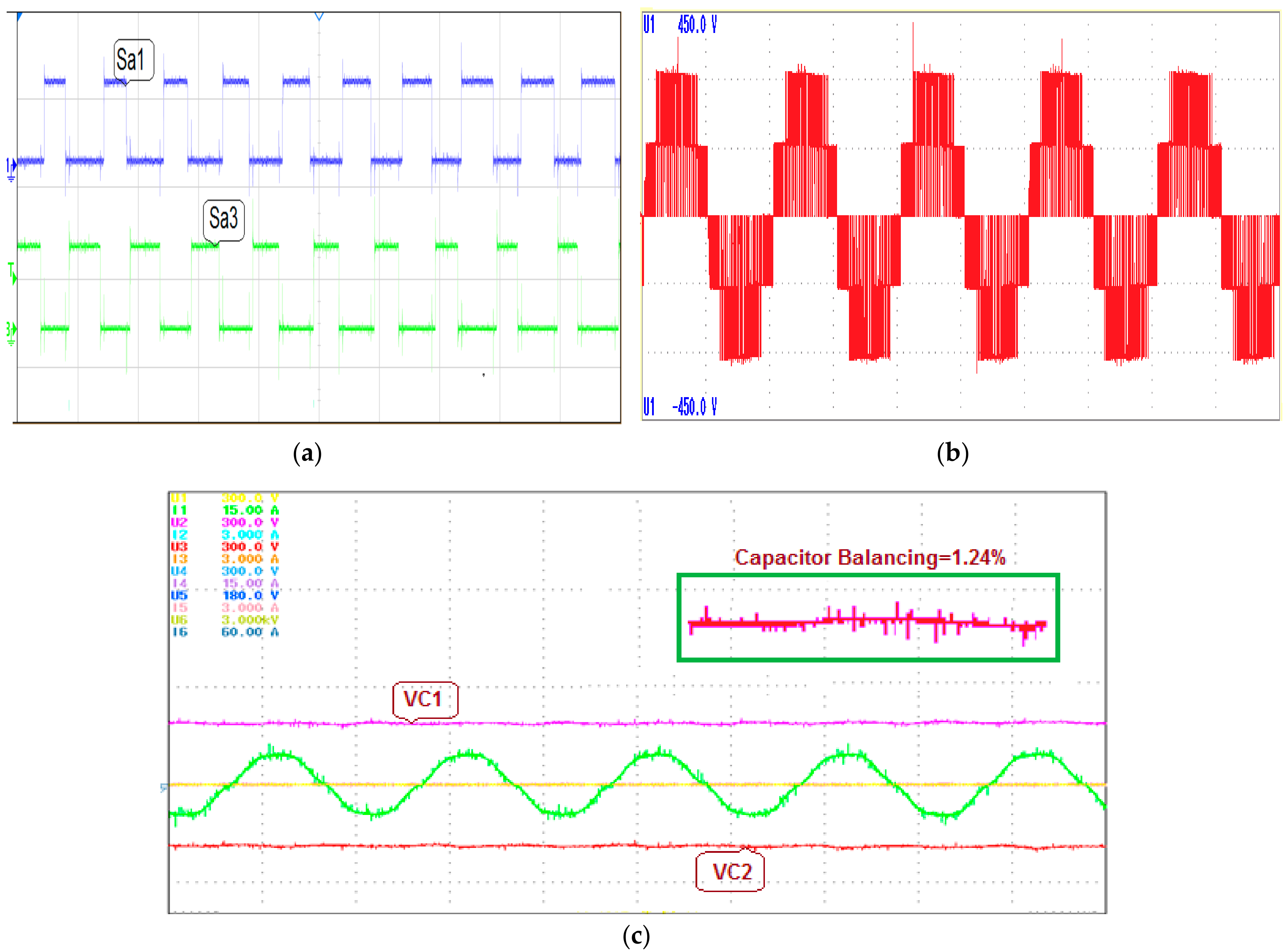
Figure 19.
Inverter output voltage and current with split inductor for different load (a) phase-A voltage with balanced load; (b) phase-A current with balanced load; (c) phase-A voltage with unbalanced load; and (d) phase-A current with unbalanced load.
Figure 19.
Inverter output voltage and current with split inductor for different load (a) phase-A voltage with balanced load; (b) phase-A current with balanced load; (c) phase-A voltage with unbalanced load; and (d) phase-A current with unbalanced load.

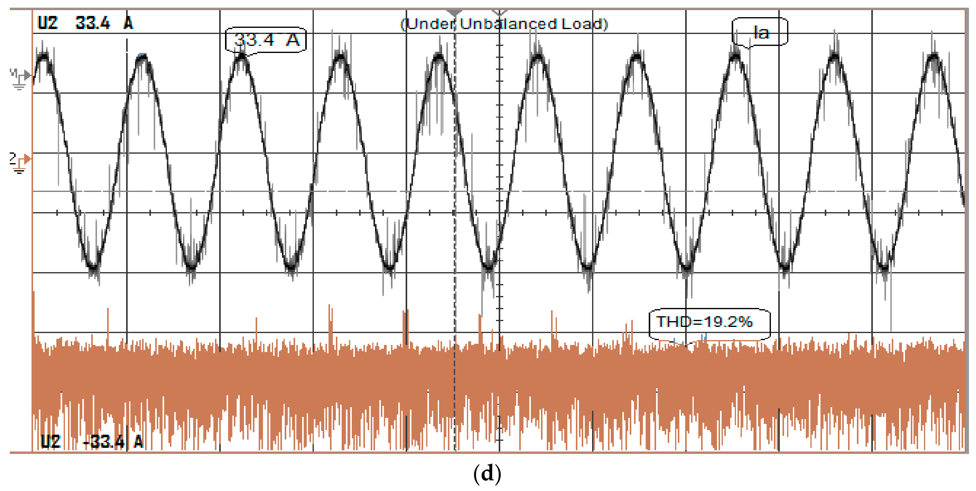
Figure 20.
(a) Comparison of output voltage and current in phase-A; and (b) THD analysis of stepped output voltage.
Figure 20.
(a) Comparison of output voltage and current in phase-A; and (b) THD analysis of stepped output voltage.

Table 1.
Parameters used in simulation and Hardware.
| Simulation Parameters | Values |
|---|---|
| DC link capacitance | 100 µF |
| Split Inductor | 4 mH |
| Solar Radiations | 300 W/m2 to 1200 W/m2 |
| Inverter switching frequency (fs) | 10 KHz |
| Temperature | 40 degree |
| PV DC-voltage | 80 V |
© 2017 by the authors. Licensee MDPI, Basel, Switzerland. This article is an open access article distributed under the terms and conditions of the Creative Commons Attribution (CC BY) license (http://creativecommons.org/licenses/by/4.0/).
Share and Cite
MDPI and ACS Style
Ramasamy, P.; Krishnasamy, V. A 3D-Space Vector Modulation Algorithm for Three Phase Four Wire Neutral Point Clamped Inverter Systems as Power Quality Compensator. Energies 2017, 10, 1792. https://doi.org/10.3390/en10111792
AMA Style
Ramasamy P, Krishnasamy V. A 3D-Space Vector Modulation Algorithm for Three Phase Four Wire Neutral Point Clamped Inverter Systems as Power Quality Compensator. Energies. 2017; 10(11):1792. https://doi.org/10.3390/en10111792
Chicago/Turabian StyleRamasamy, Palanisamy, and Vijayakumar Krishnasamy. 2017. "A 3D-Space Vector Modulation Algorithm for Three Phase Four Wire Neutral Point Clamped Inverter Systems as Power Quality Compensator" Energies 10, no. 11: 1792. https://doi.org/10.3390/en10111792
Note that from the first issue of 2016, this journal uses article numbers instead of page numbers. See further details here.