Sliding Mode Control of DFIG Wind Turbines with a Fast Exponential Reaching Law

School of Electronic Information and Electrical Engineering, Shanghai Jiao Tong University, Shanghai 200240, China
*
Author to whom correspondence should be addressed.
Energies 2017, 10(11), 1788; https://doi.org/10.3390/en10111788
Submission received: 29 September 2017
/
Revised: 24 October 2017
/
Accepted: 26 October 2017
/
Published: 7 November 2017
(This article belongs to the Section F: Electrical Engineering)
Abstract
:This paper proposes a novel sliding mode control (SMC) technique for doubly fed induction generators (DFIGs) based on the fast exponential reaching law (FERL). The proposed FERL-based SMC is capable of reducing to a large extent the chattering phenomena existing in the sliding stage. Meanwhile, the reaching stage is accelerated with the introduction of an adaptive gain. The proposed method is employed in a DFIG-based wind energy conversion system (WECS) for direct power control (DPC). The FERL-based DPC approach is tested with simulations conducted in Matlab/Simulink under the scenarios of unbalanced grid voltage, grid fault conditions and highly unstable wind speed accompanied by an experimental study. The simulations and experimental results reveal the better performance of the proposed control method in active/reactive power tracking and dc-link voltage maintenance.
1. Introduction
Wind energy is considered to be one of the major alternatives to replace fossil resources for future human society power consumption [1,2]. Wind energy conversion systems (WECSs) have the potential of tackling the forthcoming energy crisis without causing any environmental issues [2]. Among all the existing WECSs, the performance of WECSs equipped with doubly fed induction generators (DFIGs) proves to be satisfactory after long years of operation [3,4]. DFIG-based WECSs possess the advantages of high energy capture capability, less acoustic noise, high reactive power support performance and lower power rating than back-to-back power converters [5,6,7]. The reduction of the size of the DFIGs’ power converters makes the systems cost lower than other WECS schemes and makes them mostly preferred under variable wind speed scenarios [6]. Furthermore, decoupling of the active and reactive power control yields a better grid integration [2].
The control of DFIG wind turbines has arisen considerable concerns among the power and energy community. The control objectives can be generalized as maximum power extraction, dc-link voltage stabilization, grid side reactive power injection regulation and point of common coupling (PCC) current harmonics reduction [8,9,10,11,12]. Various novel maximum power point tracking (MPPT) techniques were proposed to optimize the wind energy capturing process, including the torque error forward-based optimum torque control [13], intelligent controller-based MPPT [14], and the predictive gradient ascent method-based MPPT [15]. For dc-link voltage stabilization, eigenvalue methods are employed to analyse the oscillation mode of dc-link voltage control systems [16,17]. Vector control (VC) is employed to decouple the rotor current and regulate the stator active/reactive power with proportional-integral (PI) controllers on the stator-oriented voltage frame [12,18]. The majority of DFIG control schemes are based on grid-side converter (GSC) control and rotor-side converters (RSCs) [10,11]. Despite the common interests and remarkable research results of DFIG-based WECSs achieved by power system researchers, there are still some major issues that need to be resolved, especially the grid-connection operation of DFIGs.
The control techniques can be segmented into linear control and nonlinear control approaches. Linear control approaches include the direct power control (DPC) [19], proportional integral (PI)-based pitch control [13] and linear quadratic Gaussian (LQS) approach [14]. However, most electrical components possess nonlinear behaviors and the dynamic properties of grid-connected WECS bring about parameter perturbations and external disturbances, which call for high robustness of the nonlinear control approach. SMC has been employed in controlling WECSs for years due to its very robust performance, fast response and simplicity in physical realization. A SMC control scheme is proposed and applied to a permanent-magnet synchronous generator (PMSG) wind turbine [20], wherein a combination of an exponential reaching law (ERL) and neutral point clamped (NPC) converter is utilized to balance the dc-link capacitor voltage and improve the system transient traits. A sliding mode power control of DFIG wind turbine energy conversion systems with variable wind speed is proposed in [21]. The system stability in the operation region is guaranteed with the feedback control solution under model uncertainties. In [22], a fuzzy logic-based SMC scheme is proposed to extract maximum wind power. Meanwhile, the generator-side current harmonics are mitigated with a sensorless MPPT control strategy. In [23,24], a SMC approach which is capable of regulating the active and reactive power of DFIG in a direct manner is proposed. In [23], a constant converter switching frequency is obtained with space vector modulation (SVM) and the power converter as well as harmonic filter can be simplified. However, the grid voltage is in an ideal state and no voltage disturbance is considered on the grid side. As a matter of fact, the operation of DFIG-based WECS under non-ideal grid conditions, including voltage distortion, voltage unbalance and harmonic/interharmonic current components prove to be more critical and of practical importance [25,26,27,28,29]. Hence, in [30] a SMC method was proposed to control the GSC and (RSCs of a DFIG-based WECS, where an unbalanced and harmonically distorted grid voltage condition is considered. In [31], the concept of extended active power is proposed to simplify the controller design process when the grid voltages are unbalanced. In [32], a sliding mode approach incorporating the feedback linearization theory is proposed to maintain the converter currents when the grid voltage level is far below the nominal values. The approach proposed in [33] successfully regulates the converter current when the grid voltage decreases to avoid converter damage.
Although SMC has superior performance in robustness, order reduction capability, finite-time convergence and disturbance rejection performance, its drawback of chattering phenomena caused by discontinuous switching functions largely impact its application in some specific scenarios where a strict low system frequency fluctuation requirement is needed [34,35,36,37,38,39]. To reduce or eliminate the chattering phenomena, multiple adjustable reaching laws (ARLs) are employed to take the place of constant reaching law (CRL) in SMC [35,36]. In [37], a novel SMC method with exponential reaching law (ERL) is proposed to control robot arms and the chattering phenomena is reduced to a certain extent and the reaching speed is accelerated. Apart from that, the concept of higher order sliding mode control (HOSMC) is proposed to mitigate the chattering issue with higher order derivatives of the sliding variables [40]. The introduction of super-twisting algorithms helps to avoid the utilization of discontinuous components in the control input, thus the chattering phenomena can be resolved if the system parameters are known [41]. In [31], a second order SMC scheme is proposed for power optimization of DFIG-based WECS. However, the major drawback of HOSMC is its dependence on the parametric uncertainty bounds which are usually difficult to estimate in practical scenarios [41,42], making it impractical in DFIG wind turbine control. The concept of fractional order sliding mode control (FOSMC) was proposed recently, which attempts to eliminate the chattering phenomena with the introduction of a tunable fractional order sliding surface [43,44]. However, the realization of fractional order sliding surface is based on integer order approximation, making it much too complicated to be applied in engineering scenarios practically.
The main contributions of this paper lie in two aspects: the introduction of a FERL-based SMC approach; the use of the novel SMC approach in DFIG-based WECS for DPC. In Section 2, the proposed FERL-based SMC will be introduced and its performance in controlling a nonlinear system will be evaluated with numerical simulations. In Section 3, the proposed SMC will be employed in the control of a DFIG wind turbine generator. In Section 4, a simulation and experimental test will be conducted in Matlab/Simulink and experimental platforms to perform a comparative study between the FERL-based SMC, the ERL-based SMC and the conventional PI control. The final simulation results and the experiment test verified the superior performance of the proposed FERL-based SMC method. In Section 5, a conclusion of the key features of the proposed method will be provided.
2. SMC with FERL Approach
2.1. Chattering Phenomenon
SMC method is a kind of robust control technique which is extensively utilized in nonlinear systems where parameter uncertainties exist. The general idea and concepts of SMC are available in [38] and the complete mathematical process of SMC can be found in [39]. Despite the extensive application of SMC in nonlinear system control, drawbacks still exist in these applications. One of the major weaknesses of SMC is the chattering phenomenon in the sliding mode. Another issue that needs to be addressed is the attraction speed of the state variable trajectories. Reference [37] proposed an exponential reaching law (ERL) to tackle the aforementioned two drawbacks and successfully shortened the reaching time. However, the level of the chattering phenomenon near the sliding surface does not decrease with the proposed ERL method. In the remained part of this section, we will provide the preliminaries about SMC theory and introduce the FERL method.
First consider a second order nonlinear system with control input:
where x and u are state and control vector, respectively; f and b are both bounded nonlinear functions of x and . The switching function is defined as:
where is a positive real number:
represents the tracking error and xd is the reference trajectory. In this case, the switching surface is chosen as S = 0. In the meantime, the reaching condition is generally stated as follows:
Equation (4) is utilized to guarantee that the switching function remains reaching the switching surface, thus the tracking error vector is able to slide to the equilibrium point once the switching function reaches the switching surface for the first time. In order to satisfy Equation (4), generally has the following form:
where k is a positive real number, is the sign function of S.
Substituting Equations (2)–(4) into Equation (1), we have:
where:
We need to note that Equation (7) is the continuous part of the input u, Equation (8) denotes the discontinuous part of u, and the discontinuity of Equation (8) is caused by the sign function, which subsequently results in the chattering phenomenon of the control input. It can be figured out from Equation (8) that the chattering level will be directly decided by the coefficient k if b remains constant. However, k also decides the reaching time and the robustness performance of the system. If k increases, the reaching time decreases and the robustness performance grows better, while the chattering level also becomes higher. Thus, the dilemma lies in whether to maintain a faster reaching time and robustness performance or lower chattering level.
Literature [37] proposed an exponential reaching law which is shown as bellow:
where:
where is a constant, p is a positive integer. However, our earlier research on the performance of chattering phenomenon reduction reveals that it is not capable of reducing the chattering level near the sliding surface, which is not illustrated in detail herein due to the page limitations.
2.2. FERL Approach Based SMC
In order to address the chattering phenomenon without compromising the reaching speed, we propose the following fast exponential reaching law (FERL):
where:
in which ε is a positive real number, represents the initial value of , N is a positive integer, p ≥ 2 is also an integer, r > 1. In Equation (12), is added to the dominator to guarantee that the dominator will not equal to 0 as S reaches the sliding surface. However, Equation (12) has better performance than the reaching law proposed in [37]. Firstly, the introduction of will not impact the stability of the control system for the reason that is guaranteed to be positive. Secondly, we need to observe how the gain in front of the sign function changes as grows larger and approaches 0.
Appling L’Hospital principle, we have:
Thus, as approaches positive infinity. It can be seen from Equation (14) when grows larger, the gain in the front of the sign function approaches negative infinity, which makes the attraction of the sliding surface much faster than that of the ERL method proposed in [37]. Meanwhile, when S reaches the sliding surface and = 0, then:
Considering the chattering phenomenon causes by the discontinuous term , the coefficient k will be replaced by 1/N, and subsequently the discontinuous term will become:
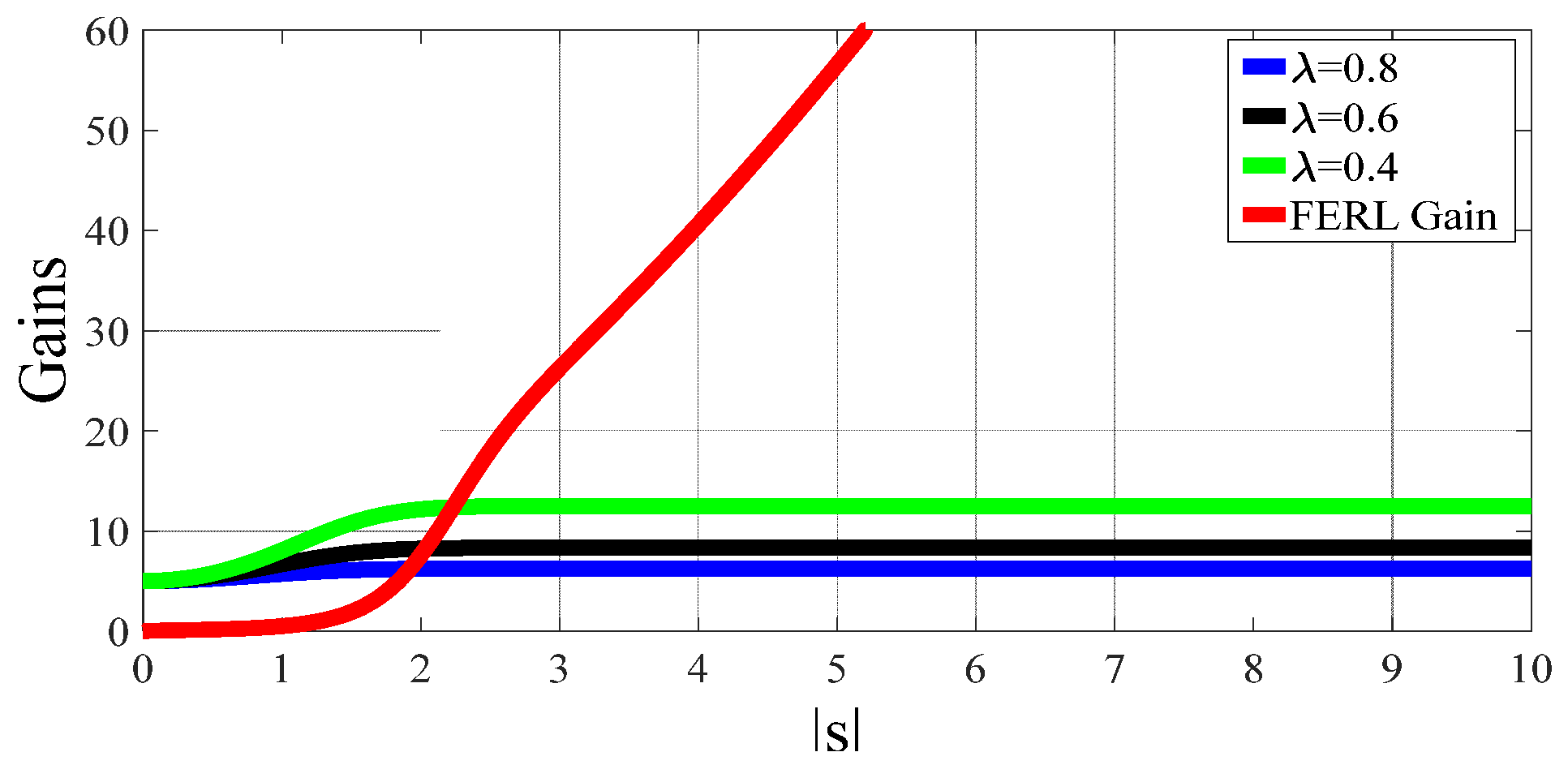
which has much smaller amplitude as long as is sufficient large. Figure 1 explicitly illustrates how the absolute value of the gains in the front of sign(S) change with S comparing different methods.
In Figure 1, the red curve is the absolute value of the FERL’s gain and the other curves are the absolute value of the ERL’s gains with different values of . It can be seen from Figure 1 that the gain of the proposed FERL method is small enough near the switching surface to limit the chattering phenomenon. As S grows larger, the gain of FERL grows much faster than the ERL method and tends to grow linearly when S is large enough, which is in accordance with the result of Equation (14). And a basic fact is that the larger the sliding mode gain grows, the faster will the reaching procedure become. Meanwhile, the choice of the initial values of the state variables has set an upper bound of the absolute value of S, which guarantees the finite time convergence of the system. Integrating both sides of Equation (14), we obtain:
where S0 stands for the initial point of the switching function; denotes the final point of the switching function, namely, the first point in the switching surface that the switching function reaches; tr represents the time for the switching function to first reaches the switching surface. Notice that = 0, we have:
where:
and:
which is non-integrable. However, numerical simulation can be applied to check the reaching speed as well as chattering phenomenon elimination performance.
Now we consider the application of the FERL method in nonlinear systems. Consider the following nonlinear system:
which can be transferred into the following second order nonlinear system:
where , . The switching surface is:
we have:
substituting the FERL reaching law Equation (11) into Equation (24), we have:
substituting Equation (25) into Equation (22), the control input can be obtained as:
We employ both the ERL- and the FERL-based SMC simultaneously in controlling the nonlinear system. The switching surface is and the parameters in Equation (11) are: , , . Meanwhile, three different values of λ are adopted in order to see how the approaching trajectory changes with λ. The state vector initial value is [11]. The reaching trajectories of both methods are shown in Figure 2 and Figure 3. The iteration times for the ERL method are 3.986 s, 4.178 s and 4.659 s, and the iteration time for the FERL method is 3.652 s.
One important phenomenon we can observe from Figure 2 is that the first intersection point of the FERL method is closer to the equilibrium, hence, the system experiences a shorter chattering stage, which is also one of the major strengths of the FERL method. Meanwhile, we can see from Figure 3 that the chattering level of the FERL method near the switching surface is much smaller than that of the other methods. Thus, the proposed FERL method has better performance in reaching speed and chattering phenomenon elimination.
3. DFIG Wind Turbine Application
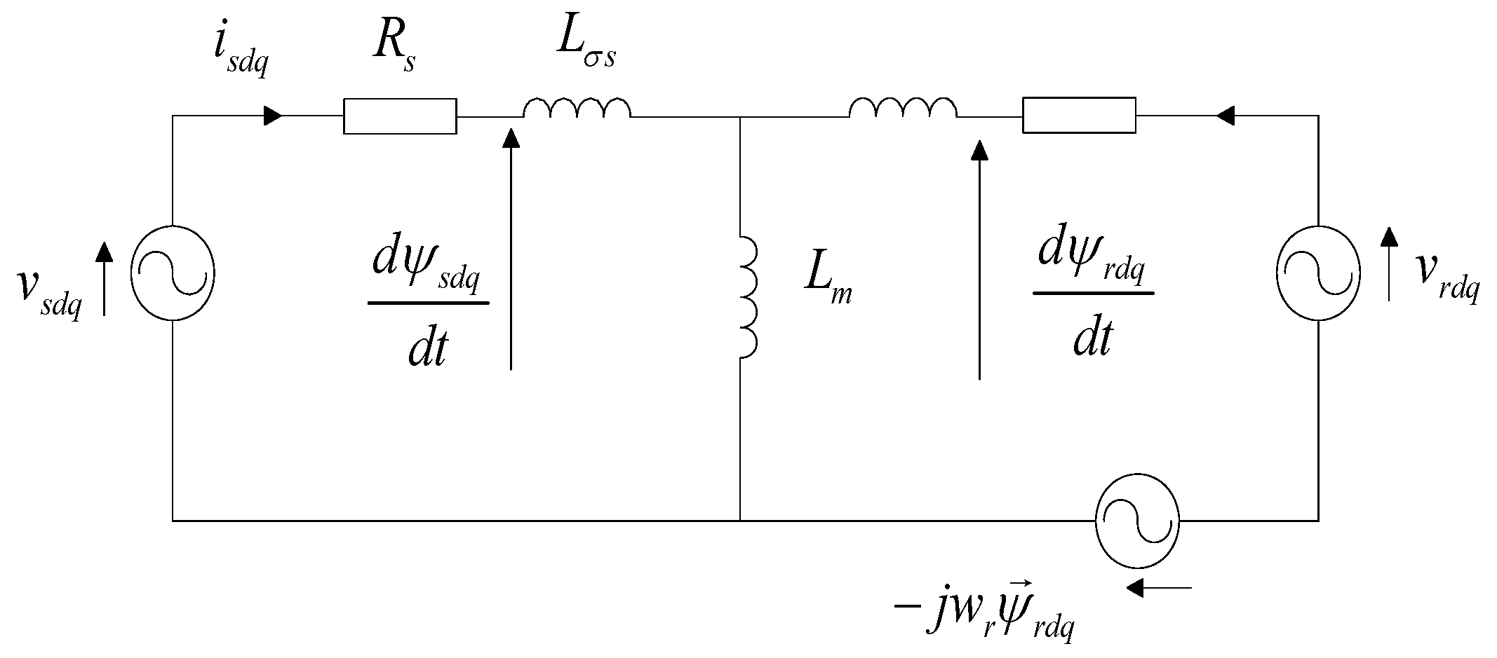
The basic structure of DFIG-based wind turbine can be found in [19,23]. The mission of a DFIG wind turbine generator control is to keep the active and reactive power injected to the grid tracking well the reference value. The equivalent circuit of a DFIG in the stators’ reference frame is shown in Figure 4 and the stator/rotor voltage vectors in the synchronously rotating frame of the reference are shown as [45,46]:
where , represent the flux linkage vectors of the stator and rotor, respectively; , are the self-inductances of the stator and the rotor, respectively; denotes the mutual inductance, , are the current vectors of the stator and rotor, respectively.
Meanwhile, Figure 5 provides the expression of the stator and the rotor voltage vectors as shown below:
where , are the stator and rotor voltage vectors, , are the stator and rotor resistances, is the rotor angular velocity. Based on Equations (27) and (28), we have:
where . Consider an ideal network with the and components of the voltage being stated as follows [46,47]:
Meanwhile, the instantaneous active and reactive power injected to the grid by the wind turbine are expressed as [47]:
Now we construct the sliding surfaces as:
where:
in which , stand for the errors between the reference and the actual active/reactive power. Hence, the derivative of S is:
Based on Equations (32)–(34), the complete form of Equation (35) is:
where , , , .
Now in order to make sure that Equation (4) holds, we substitute Equation (9) into Equation (36), which yields:
thus, the control input is:
where the stator flux estimation is carried out to calculate the stator flux as stated below:
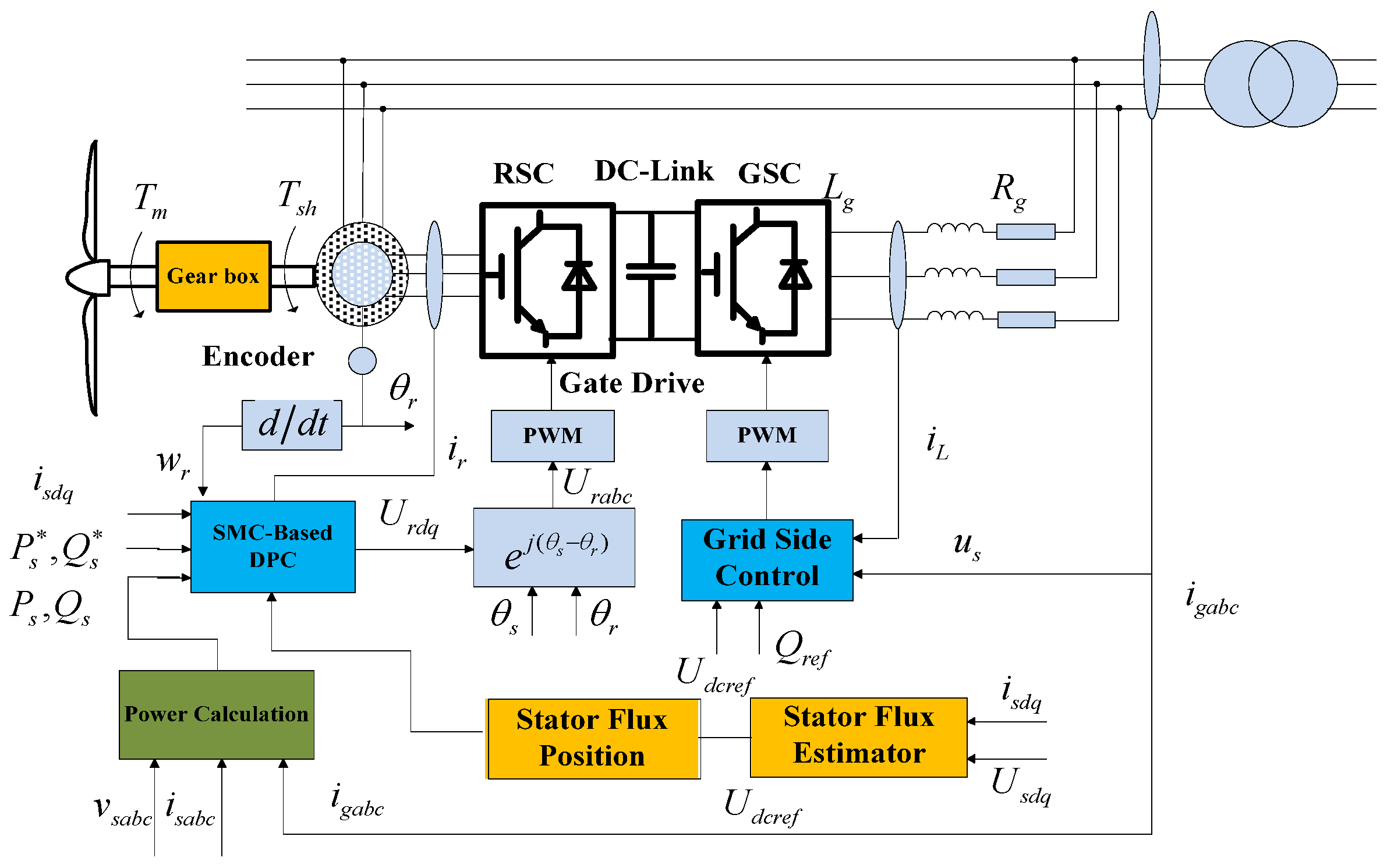
The corresponding control diagram of the DFIG-based WECS is shown in Figure 5.
4. Stability Analysis
A stability analysis is essential for deriving the system requirements that guarantee the stability of the system and force the state trajectories to the equilibrium manifold. The Lyapunov function approach is generally employed for the stability analysis. We select the following Lyapunov candidate function:
which remains semi-positive all the time. The time derivative of is:
Substituting the control law into Equation (41), we have:
where , . Hence, remains negative without any further constraints for the control parameters and the asymptotic convergence of the system state variables can be guaranteed.
5. Simulation and Experiment
The simulation is conducted in Matlab/Simulink. The nominal power output of the DFIG generator and the dc-link voltage are 2 MW, respectively. The converter switching frequency is 2 kHz for both the RSC and the GSC. The remaining system parameters involved are listed in Table 1.
5.1. Performance Evaluation under Unbalanced Grid Voltage and Gust Wind
Similar settings are employed as stated in [30]. The ERL SMC, the FERL SMC scheme and the conventional PI control approaches are implemented in the simulation diagram in the form of an S function with Matlab programming and the solver of the program is chosen as ode45 (Runge-Kutta) with the sampling time step of 50 μs.
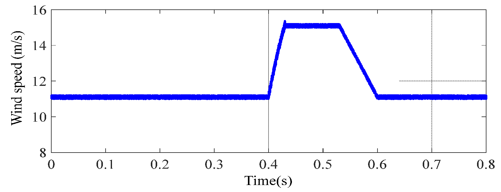
The wind speed remains constant at v = 11 m/s before t = 0.5 s and a gust wind occurs at t = 0.5 s, which is shown in Figure 6. Meanwhile, a two-phase 20% voltage drop happens between t = 0.2 s and t = 0.5 s. Such voltage drops can be caused by unbalanced load distributions or faults. Figure 7 illustrates the different performances of the three methods in active/reactive power tracking and dc-link voltage support. There are in total four stages of the reference power curve. The first stage ranges from to t = 0.2 s as no grid voltage or wind speed changes. The second stage begins at t = 0.2 s when a 20% voltage drop occurs. The third stage begins at t = 0.4 s when the gust wind comes and ends at t = 0.5 s when the grid voltages drop back to the original value. The fourth stage begins at t = 0.5 s and ends with the simulation termination. It is evidently seen by comparing Figure 7 that with the proposed FERL-based SMC method, the stator active and reactive power achieve a better and smoother match to the reference active and reactive values than those of the ERL-based SMC method and the conventional PI control. Furthermore, the maximum dc-link voltage deviation during the voltage drop and gust wind period is reduced from 29.5 V to as small as 17.3 V, which further illustrates the superior performance of the proposed method. Meanwhile, the higher robustness of the general SMC approaches can be witnessed by comparing the simulation results of the DC-link voltages, the stator and rotor currents as shown in Figure 7b,e,f, respectively. The ERL-based SMC and the FERL-based SMC both show better robustness performance than that of the conventional PI approach. In order to evaluate the tracking performance of both methods in a quantitative manner, the integral square error (ISE) is adopted, which is defined as [48]:
where e(t) represents the error between the reference and the actual value. The normalized ISE indices of the active and reactive power tracking curves of the ERL method are 90.6686 and 24.4783, respectively; those of the FERL method are 7.6838 and 2.3879, respectively; and those of the PI approach are 105.7833 and 36.3287, respectively. Evidently, the tracking errors of the ERL-based SMC and the PI control are much larger than those of the FERL method referring to the ISE indices of both the active and reactive power tracking.
5.2. Performance Evaluation under Grid Fault Condition
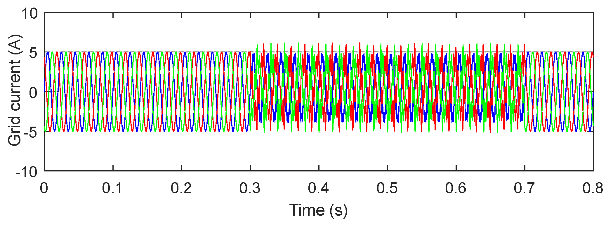
A more severe fault scenario is simulated to further test the performance of the proposed method, where a single to ground fault with 40% dip depth, a 20% of the 5th and 20% of the 7th order harmonics together with 30% of reduction of the parameters , , and are initialized in between 0.3 s and 0.7 s. Figure 8 shows the grid current in the grid fault condition.
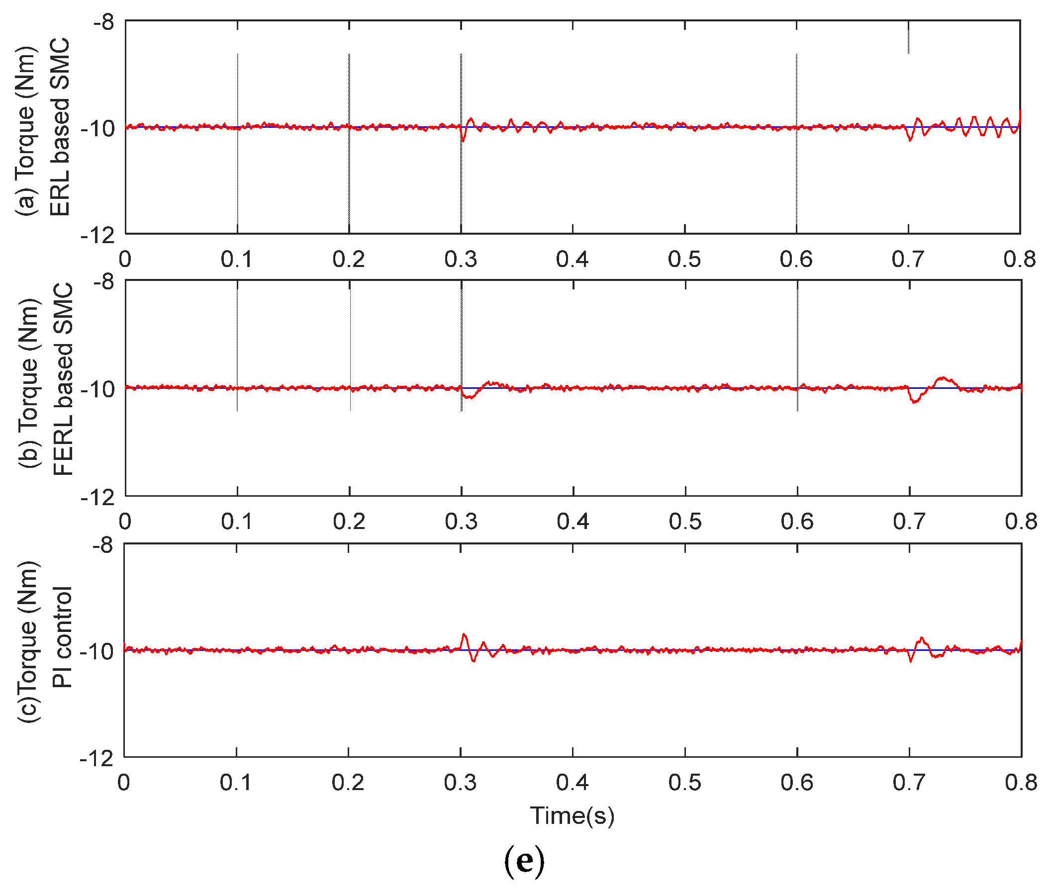
Figure 9 shows the simulation results of the ERL- and FERL-based SMC, and the PI control. It can be seen by Figure 9 that the rotor/stator currents and the active/reactive tracking performance of all the three methods are impacted by the grid fault. However, with the FERL method, the influences are smaller and the active/reactive power outputs track better than that of the ERL method. Meanwhile, Figure 9a,b reveals that the SMC approaches have better robustness capability than the PI control. When the grid fault occurs, the rotor and stator currents of the PI control experienced higher impacts than that of the SMC approaches. Meanwhile, Figure 9c–e reveals that the conventional SMC approach shows its weakness in chattering phenomena, while the novel SMC approach largely mitigated the chatter.
5.3. Performance Evaluation under Variable Wind Speed
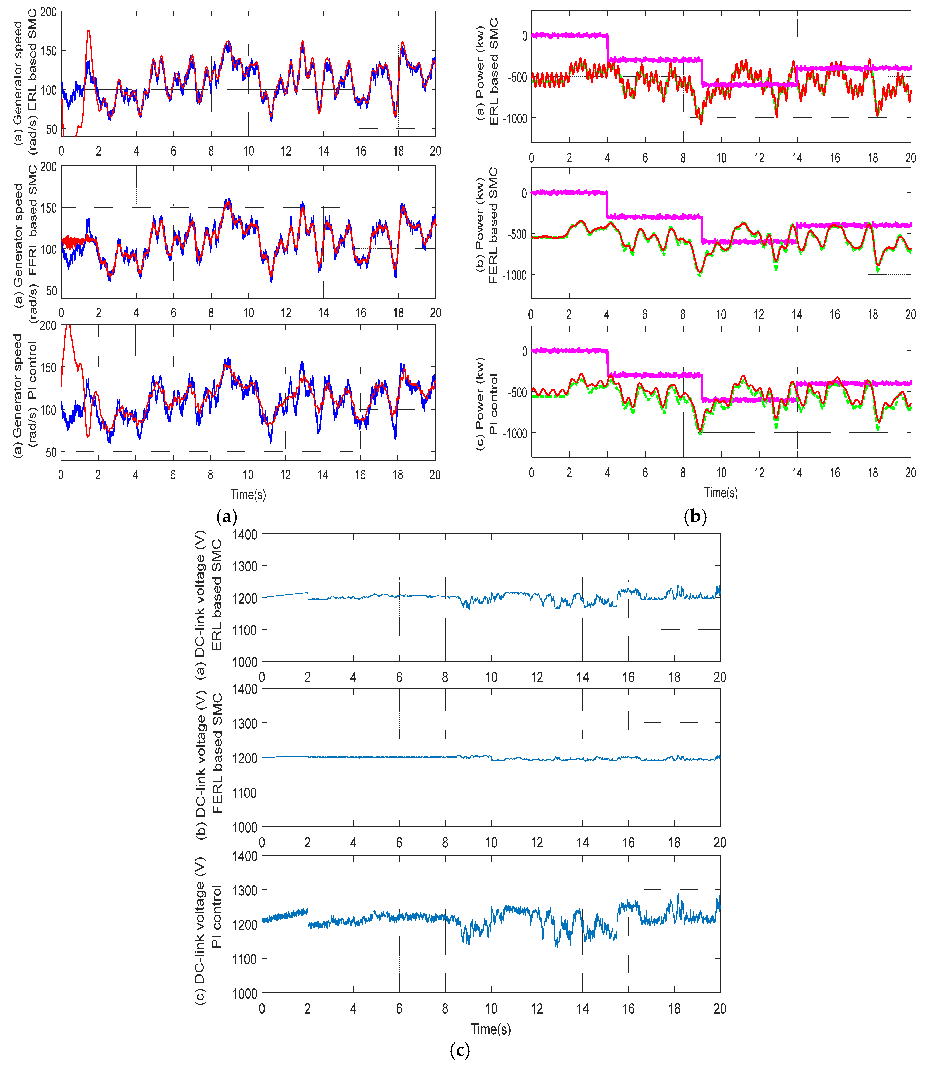
In order to test the performance of the proposed method in maximum power extraction, dc-link voltage and reactive power control, the simulation is conducted under the variable wind speed (VWS) scenario. VWS is capable of simulating the actual operation situation of a practical wind turbine. Adopting the modeling approach proposed in [49], the simulated VWS is shown in Figure 10. Before t = 2 s, the wind speed is stabilized at v = 11 m/s. The VWS starts at t = 2 s and changes randomly until t = 20 s
Figure 11 represents the maximum power extraction and dc-voltage support under variable wind speed with the conventional ERL method, the proposed FERL method and the PI control. Figure 11a illustrates the generator reference speed and the actual speed. Figure 11b shows the system power outputs and the corresponding maximum power. Figure 11c denotes the dc-link voltage. Comparing the figures in Figure 11a, although there is no apparent difference in the tracking performance of all the methods, it is evident that less chattering exists in the curve of the actual speed with the FERL method than that of the ERL method. Meanwhile, Figure 11b also evidences the superior performance of the proposed method in active power tracking and dc-voltage maintenance when comparing with the simulation results of the other methods. Figure 12 shows the ISE indices of the three methods in different time periods. The ISE indices are calculated every 0.5 s in order to show the tendency of tracking. Obviously, FERL-based SMC has smaller ISE indices than the ERL method and the PI control, and the ISE indices is stabilized in the entire time range.
5.4. Experimental Test
The proposed FERL-based SMC approach is further tested via experiments. The test bed is made of a 2 kW induction generator, a 0.7-kW doubly fed inverter and necessary current/voltage sensors [50]. It is worth noting that the nominal power of the inverter has no direct relationship with the nominal value of the wind turbine. Instead, it is decided based on the storage battery nominal value and the load value. When there is a load, the nominal value of the inverter power should be 10–30% larger than the load value. A 1716 Data Acquisition Card is employed to connect the sensors with computer. A dSPACEDS 1103 DSP (Texas Instructment, Dallas, TX, USA) board is utilized to control the RSC and the GSC. A TMS320F2812DSP (Texas Instructment, Dallas, TX, USA) is employed to serve as the microprocessor which generates the control signal for the DFIG-based WECS with 20 MHz frequency. The test bed is shown in Figure 13. The remaining parameters are initialized to be the identical as those of the simulation. The wind speed file is adopted from Cangnan Wind Energy Center in Zhejiang Province (China) and the horizon of the wind file is also 20 s.
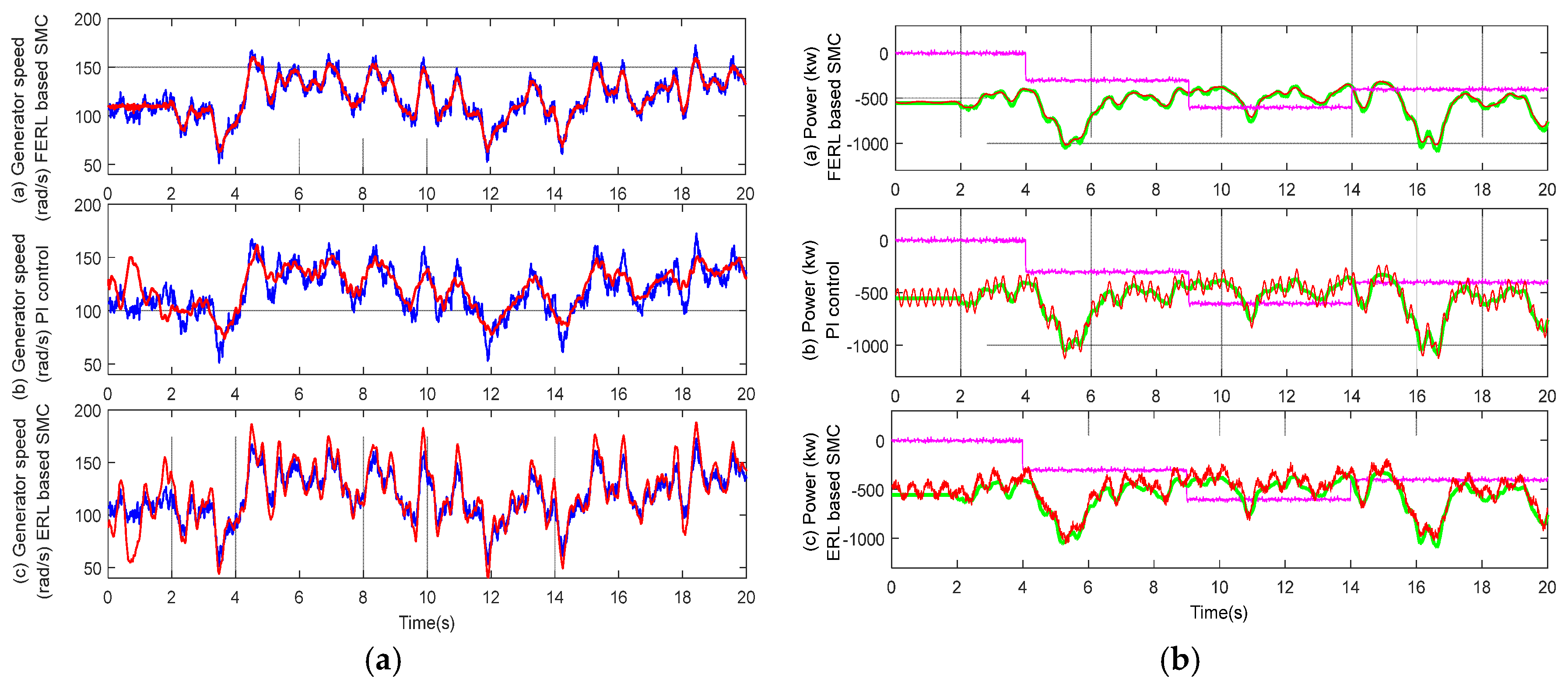
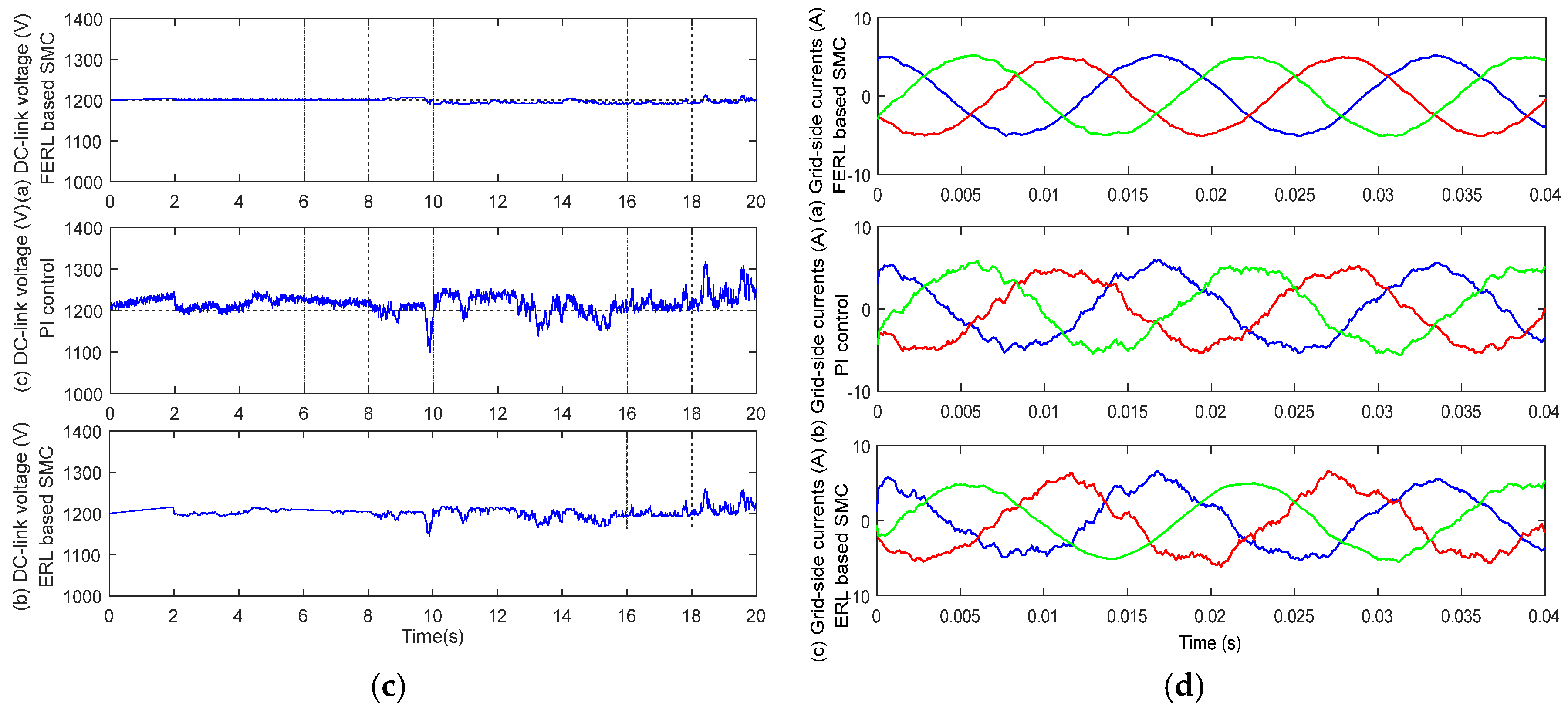
Figure 14 compares the tracking capability of the FERL-based SMC, the ERL-based SMC and the PI approach. It is evident that the proposed method tracks the reference generator curve best. Figure 14b represents the active power tracking curves of the aforementioned three methods.
It is evident that the ERL-based SMC contains high frequency chatter, while the actual active power of the FERL-based SMC tracks the reference curve well without obvious chatter. Figure 14c shows the DC-link voltage curves of the three methods and it can be seen that the DC-link voltage of the proposed method remains stabilized. Figure 14d shows the grid side currents of the three methods. Their THD levels are 1.35%, 7.29%, and 7.97%, respectively. The chatter elimination capability of the proposed method guarantees that the actual power curves can track the reference curves smoothly. Hence, the system can operate in a more ideal state.
6. Conclusions
This paper proposes a novel SMC method based on FERL to control DFIG wind turbine. The proposed FERL-based SMC method aims to promote the performance of the ERL-based SMC by introducing an adaptive term which can change rapidly as the absolute value of the switching function grows in order to accelerate the reaching progress and mitigate chattering phenomena. The numerical simulation of a nonlinear case verified the superior performance of the proposed method.
The proposed method is employed directly to control a DFIG-based wind turbine. The control objectives are to regulate the active/reactive power output and support the dc-link voltage under different operation conditions. The direct and quaradture rotor voltages serve as the control input of the WECS. Meanwhile, a stability analysis is conducted to verify the asymptotic convergence of the state variables with the final control signal. Simulations are conducted in Matlab/Simulink and three different operational conditions are considered: unbalanced grid voltage together with gust wind condition, single phase-to-ground grid fault condition, and variable wind speed condition. A simulation is conducted to compare the performance of the novel approach, the ERL-based SMC and the conventional PI approach. The simulation results reveal that the proposed FERL-based SMC has better performance in capturing the optimal wind energy and active/reactive power regulation capability. Meanwhile, the proposed approach also exhibits high robustness to external disturbances. After the simulations, an experimental study is carried out and the results indicate that the proposed method shows better performance in generator speed and active power tracking, DC-link voltage maintenance as well as THD mitigation.
Acknowledgments
Support of the National Natural Science Foundation of China under Grant No. 61374155, and the Specialized Research Fund for the Doctoral Program of Higher Education P R China under Grant No. 20130073110030 is highly acknowledged.
Author Contributions
Linyun Xiong proposed the control technique, conducted the matlab simulation and wrote the paper; Penghan Li helped in constructing the Matlab platform and the experimental setups; Hao Li helped in data acquisition, data processing and manuscript checking; Jie Wang is responsible for the quality of the paper.
Conflicts of Interest
The authors declare no conflict of interest.
References
- Stiebler, M. Wind Energy Systems for Electric Power Generation; Springer: New York, NY, USA, 2008. [Google Scholar]
- Zavadil, R.; Miller, N.; Ellis, A.; Muljadi, E. Making connections: Wind generation challenges and progress. IEEE Power Energy Mag. 2005, 3, 26–37. [Google Scholar] [CrossRef]
- Wagner, H.-J.; Mathur, J. Introduction to Wind Energy Systems Basics, Technology and Operation; Springer: New York, NY, USA, 2009. [Google Scholar]
- Abad, G.; Lopez, J.; Rodriguez, M.; Marroyo, L.; Iwanski, G. Doubly Fed Induction Machine; Wiley: Hoboken, NJ, USA, 2011. [Google Scholar]
- Wu, B.; Lang, Y.; Zargari, N.; Kouro, S. Power Conversion and Control of Wind Energy Systems; Wiley: Hoboken, NJ, USA, 2011. [Google Scholar]
- Datta, R.; Ranganathan, V.T. Variable-speed wind power generation using doubly fed wound rotor induction machine-a comparison with alternative schemes. IEEE Trans. Energy Convers. 2002, 17, 414–421. [Google Scholar] [CrossRef]
- Liao, K.; He, Z.; Xu, Y.; Chen, G.; Dong, Z.Y.; Wong, K.P. A sliding mode based damping control of DFIG for interarea power oscillations. IEEE Trans. Sustain. Energy 2017, 8, 258–267. [Google Scholar] [CrossRef]
- Yamamoto, M.; Motoyoshi, O. Active and reactive power control for doubly-fed wound rotor induction generator. IEEE Trans. Power Electron. 1991, 6, 624–629. [Google Scholar] [CrossRef]
- Akagi, H.; Sato, H. Control and performance of a doubly-fed induction machine intended for a flywheel energy storage system. IEEE Trans. Power Electron. 2002, 17, 109–116. [Google Scholar] [CrossRef]
- Blaabjerg, F. Future on power electronics for wind turbine systems. IEEE J. Emerg. Sel. Top. Power Electron. 2013, 1, 139–152. [Google Scholar] [CrossRef]
- Muller, S.; Deicke, M.; De Doncker, R.W. Doubly fed induction generator systems for wind turbines. IEEE Ind. Appl. Mag. 2002, 8, 26–33. [Google Scholar] [CrossRef]
- Hu, J.; He, Y.; Xu, L.; Williams, B.W. Improved control of DFIG systems during network unbalance using PI-R current regulators. IEEE Trans. Ind. Electron. 2009, 56, 439–451. [Google Scholar] [CrossRef]
- Cui, Z.; Song, L.; Li, S. Maximum power point tracking strategy for a new wind power system and its design details. IEEE Trans. Energy Convers. 2017, 32, 1063–1071. [Google Scholar] [CrossRef]
- Rahmanian, E.; Akbari, H.; Sheisi, G.H. Maximum power point tracking in grid connected wind plant by using intelligent controller and switched reluctance generator. IEEE Trans. Sustain. Energy 2017, 8, 1313–1320. [Google Scholar] [CrossRef]
- Kim, C.; Gui, Y.; Chung, C.C. Maximum power point tracking of a wind power plant with predictive gradient ascent method. IEEE Trans. Sustain. Energy 2017, 8, 685–694. [Google Scholar] [CrossRef]
- Hu, J.; Huang, Y.; Wang, D.; Yuan, H.; Yuan, X. Modeling of grid-connected DFIG-based wind turbines for DC-link voltage stability analysis. IEEE Trans. Sustain. Energy 2015, 6, 1325–1336. [Google Scholar] [CrossRef]
- Zhou, P.; Yuan, X.; Hu, J. Stability of DC-link voltage as affected by phase locked loop in VSC when attached to weak grid. In Proceedings of the IEEE Power Energy PES General Meeting, National Harbor, MD, USA, 27–31 July 2014; pp. 1–5. [Google Scholar]
- Luo, A.; Tang, C.; Shuai, Z.; Tang, J.; Xu, X.; Chen, D. Fuzzy-PI based direct-output-voltage control strategy for the STATCOM used in utility distribution systems. IEEE Trans. Ind. Electron. 2009, 56, 2401–2411. [Google Scholar] [CrossRef]
- Zhi, D.; Xu, L. Direct power control of DFIG with constant switching frequency and improved transient performance. IEEE Trans. Energy Convers. 2007, 22, 110–118. [Google Scholar] [CrossRef]
- Mozayan, S.M.; Saad, M.; Vahedi, H.; Blanchette, H.F.; Soltani, M. Sliding mode control of PMSG wind turbine based on enhanced exponential reaching law. IEEE Trans. Ind. Electron. 2016, 63, 6148–6159. [Google Scholar] [CrossRef]
- Beltran, B.; Ali, T.A.; Benbouzid, M.E. Sliding mode power control of variable-speed wind energy conversion systems. IEEE Trans. Energy Convers. 2008, 23, 551–558. [Google Scholar] [CrossRef] [Green Version]
- Yin, X.X.; Lin, Y.G.; Li, W.; Liu, H.W.; Gu, Y.J. Fuzzy-logic sliding mode control strategy for extracting maximum wind power. IEEE Trans. Energy Convers. 2015, 30, 1267–1278. [Google Scholar] [CrossRef]
- Hu, J.; Nian, H.; Hu, B.; He, Y.; Zhu, Z.Q. Direct active and reactive power regulation of DFIG using sliding-mode control approach. IEEE Trans. Energy Convers. 2010, 25, 1028–1039. [Google Scholar] [CrossRef]
- Evangelista, C.; Valenciaga, F.; Puleston, P. Active and reactive power control for wind turbine based one a MIMO 2-sliding mode algorithm with variable gains. IEEE Trans. Energy Convers. 2013, 3, 682–689. [Google Scholar] [CrossRef]
- Wang, J.; Tse, N.; Gao, Z. Synthesis on PI-based pitch contrlller of large wind turbines generator. Energy Convers. Manag. 2011, 52, 1288–1294. [Google Scholar] [CrossRef]
- Munteanu, I.; Cutululis, N.A.; Bratcu, A.I. Optimization of variable speed wind power systems based on a LQG approach. Control Eng. Pract. 2005, 13, 903–912. [Google Scholar] [CrossRef]
- Shang, L.; Hu, J. Sliding mode based direct power control of grid connected wind turbine driven doubly fed induction generators under unbalanced grid voltage conditions. IEEE Trans. Energy Convers. 2012, 27, 362–373. [Google Scholar] [CrossRef]
- Hu, J.; Xu, H.; He, Y. Coordinated control of DFIG’s RSC and GSC under generalized unbalanced and distorted grid voltage conditions. IEEE Trans. Ind. Electron. 2013, 60, 2808–2819. [Google Scholar] [CrossRef]
- Dehkordi, N.M.; Sadati, N.; Hamzeh, M. A robust backstepping high order sliding mode control strategy for grid connected DG units with harmonic/interharmonic current compensation capability. IEEE Trans. Sustain. Energy 2017, 8, 561–572. [Google Scholar] [CrossRef]
- Martinez, M.I.; Tapia, G.; Susperregui, A.; Camblong, H. Sliding-mode control for DFIG rotor-and grid-side converters under unbalanced and harmonically distorted grid voltage. IEEE Trans. Energy Convers. 2012, 27, 328–339. [Google Scholar] [CrossRef]
- Sun, D.; Wang, X.; Nian, H.; Zhu, Z.Q. A Sliding-Mode Direct Power Control Strategy for DFIG Under Both Balanced and Unbalanced Grid Conditions Using Extended Active Power. IEEE Trans. Power Electron. 2017, 33, 1313–1322. [Google Scholar] [CrossRef]
- Matas, J.; Castilla, M.; Guerrero, J.M.; Vicuna, L.G.; Miret, J. Feedback linearization of direct-drive synchronous wind-turbines via a sliding mode approach. IEEE Trans. Power Electron. 2008, 23, 1093–1103. [Google Scholar] [CrossRef]
- Liu, X.; Han, Y.; Wang, C. Second-order sliding mode control for power optimization of DFIG-based variable speed wind turbine. IET Renew. Power Gener. 2017, 2, 408–418. [Google Scholar] [CrossRef]
- Hao, X.; Yang, X.; Liu, T.; Huang, L.; Chen, W. A sliding-mode controller with multiresonant sliding surface for single-phase grid-connected VSI with an LCL filter. IEEE Trans. Power Electron. 2013, 28, 2259–2268. [Google Scholar] [CrossRef]
- Zhao, X.; Yang, H.; Zong, G. Adaptive neural hierarchical sliding mode control of nonstrict-feedback nonlinear systems and an application to electronic circuits. IEEE Trans. Syst. Man Cybern. 2013, 47, 1394–1404. [Google Scholar] [CrossRef]
- Gao, W.; Hung, J.C. Variable structure control of nonlinear systems: A new approach. IEEE Trans. Ind. Electron. 1993, 40, 45–55. [Google Scholar]
- Fallaha, C.J.; Saad, M.; Kanaan, H.Y.; Al-Haddad, K. Sliding-mode robot control with exponential reaching law. IEEE Trans. Ind. Electron. 2011, 58, 600–610. [Google Scholar] [CrossRef]
- Slotine, J.; Li, W. Applied Nonlinear Control; Prentice-Hall: Englewood Cliffs, NJ, USA, 1991. [Google Scholar]
- Krstic, M.; Kanellakopoulos, I.; Kokotovic, P. Nonlinear and Adaptive Control Design; Wiley: New York, NY, USA, 1995. [Google Scholar]
- Emel’yanov, S.V.; Korovin, S.K.; Levant, A. High-order sliding modes in control systems. Comput. Math. Model. 1996, 7, 294–318. [Google Scholar] [CrossRef]
- Laghrouche, S.; Harmouche, M.; Ahmed, F.S.; Chitour, Y. Control of PEMFC air-feed system using Lyapunov-based robust and adaptive higher order sliding mode control. IEEE Trans. Control Syst. Technol. 2015, 23, 1594–1601. [Google Scholar] [CrossRef]
- Harmouche, M.; Laghrouche, S.; Chitour, Y. Robust and adaptive higher order sliding mode controllers. In Proceedings of the 51st IEEE Conference on Decision and Control (CDC), Maui, HI, USA, 10–13 December 2012; pp. 6436–6441. [Google Scholar]
- Ullah, N.; Wang, S. Fractional order adaptive fuzzy sliding mode controller for a position servo system subjected to aerodynamic loading and nonlinearities. Aerosp. Sci. Technol. 2015, 43, 381–387. [Google Scholar] [CrossRef]
- Davijani, N.Z.; Jahanfarnia, G.; Abharian, A.E. Nonlinear fractional sliding mode controller based on reduced order FNPK model for output power control of nuclear research reactors. IEEE Trans. Nucl. Sci. 2017, 64, 713–723. [Google Scholar] [CrossRef]
- Choi, D.; Lee, K. Dynamic performance improvement of AC/DC converter using model predictive direct power control with finite control set. IEEE Trans. Ind. Electron. 2015, 62, 757–767. [Google Scholar] [CrossRef]
- Kumar, V.; Thukaram, D. Accurate steady-state representation of a doubly fed induction machine. IEEE Trans. Power Electron. 2015, 30, 5370–5375. [Google Scholar] [CrossRef]
- Errouissi, R.; Durra, A.A.; Muyeen, S.M.; Leng, S.; Blaabjerg, F. Offset-free direct power control of DFIG under continuous-time model predictive control. IEEE Trans. Power Electron. 2017, 32, 2265–2277. [Google Scholar] [CrossRef]
- Ling, K.V.; Ho, W.K.; Feng, Y.; Wu, B. Integral-square error performance of multiplexed model predictive control. IEEE Trans. Ind. Electron. 2011, 7, 196–203. [Google Scholar] [CrossRef]
- Rawn, B.G.P.; Lehn, W.; Maggiore, M. Control methodology to mitigate the grid impact of wind turbines. IEEE Trans. Energy Convers. 2007, 22, 431–438. [Google Scholar] [CrossRef]
- Tohidi, A.; Hajieghrary, H.; Hsieh, M.A. Adaptive disturbance rejection control scheme for DFIG-based wind turbine: Theory and experiments. IEEE Trans. Ind. Appl. 2016, 52, 2006–2015. [Google Scholar] [CrossRef]
Figure 1.
Gains of different methods. FERL: fast exponential reaching law.

Figure 2.
Reaching trajectories in non-linear system.
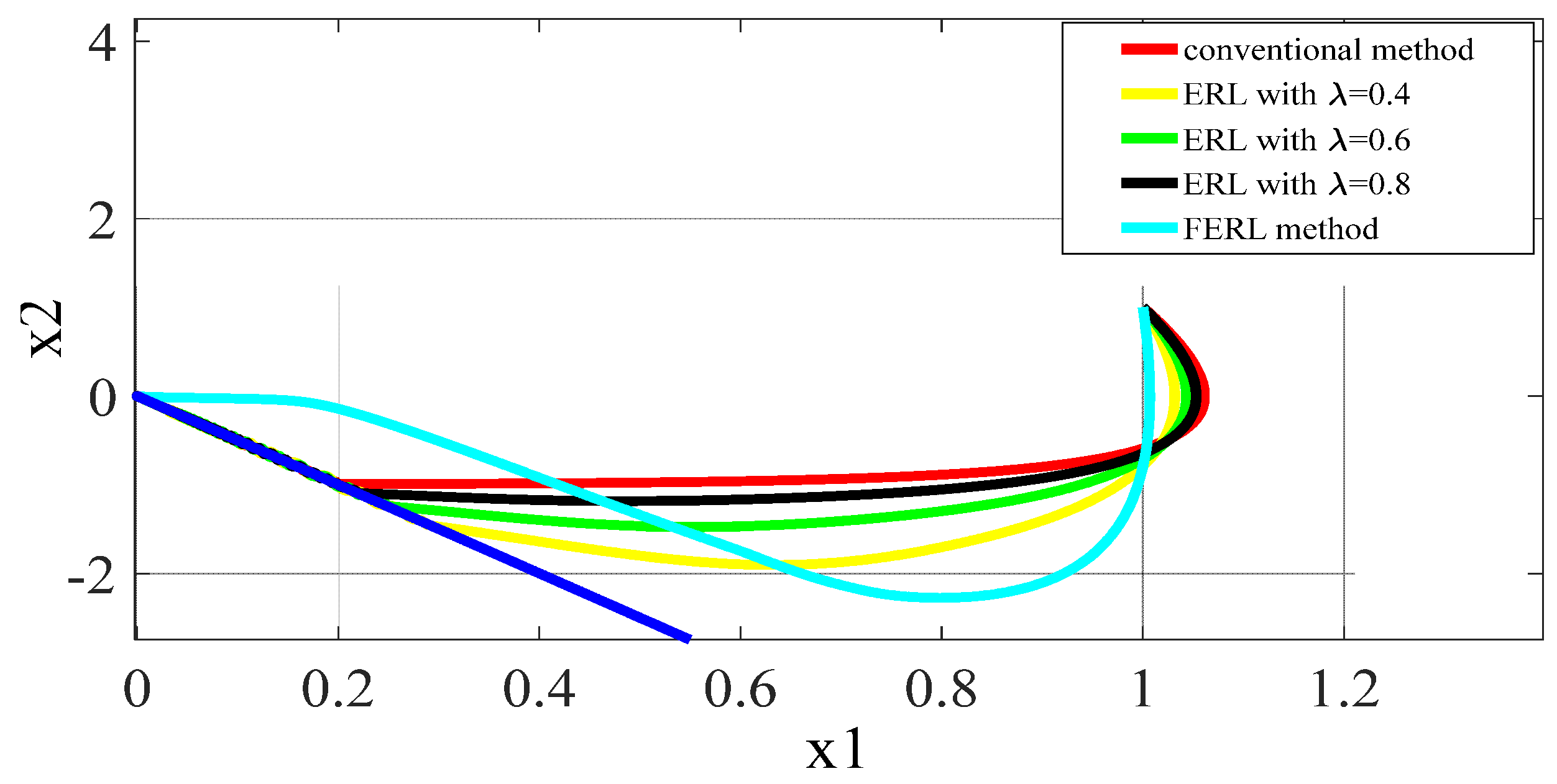
Figure 3.
Amplified figure of the trajectories near the switching surface.
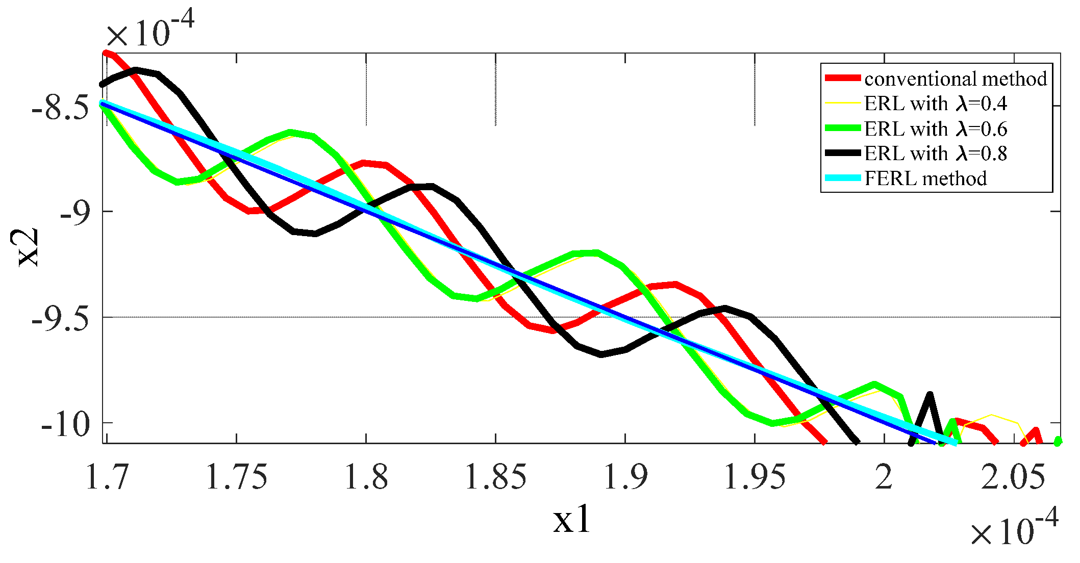
Figure 4.
Equivalent circuit of doubly fed induction generator (DFIG) wind turbine.

Figure 5.
Control diagram of DFIG-based wind energy conversion system (WECS) with the sliding mode control (SMC)-based direct power control (DPC) approach.
Figure 5.
Control diagram of DFIG-based wind energy conversion system (WECS) with the sliding mode control (SMC)-based direct power control (DPC) approach.

Figure 6.
Gust wind speed curve.

Figure 7.
Simulation results with grid voltage drop/gust wind comparing three different approaches: (a) three phase grid voltage and current; (b) DC-link voltages; (c) Stator active power performances; (d) Stator reactive power performances; (e) Rotor currents; (f) Stator currents).
Figure 7.
Simulation results with grid voltage drop/gust wind comparing three different approaches: (a) three phase grid voltage and current; (b) DC-link voltages; (c) Stator active power performances; (d) Stator reactive power performances; (e) Rotor currents; (f) Stator currents).

Figure 8.
Grid current under grid fault condition.

Figure 9.
Simulation results under grid fault condition comparing three different approaches: (a) Rotor currents; (b) Stator currents; (c) Stator active power performances; (d) Stator reactive power performances; (e) Generator torque.
Figure 9.
Simulation results under grid fault condition comparing three different approaches: (a) Rotor currents; (b) Stator currents; (c) Stator active power performances; (d) Stator reactive power performances; (e) Generator torque.
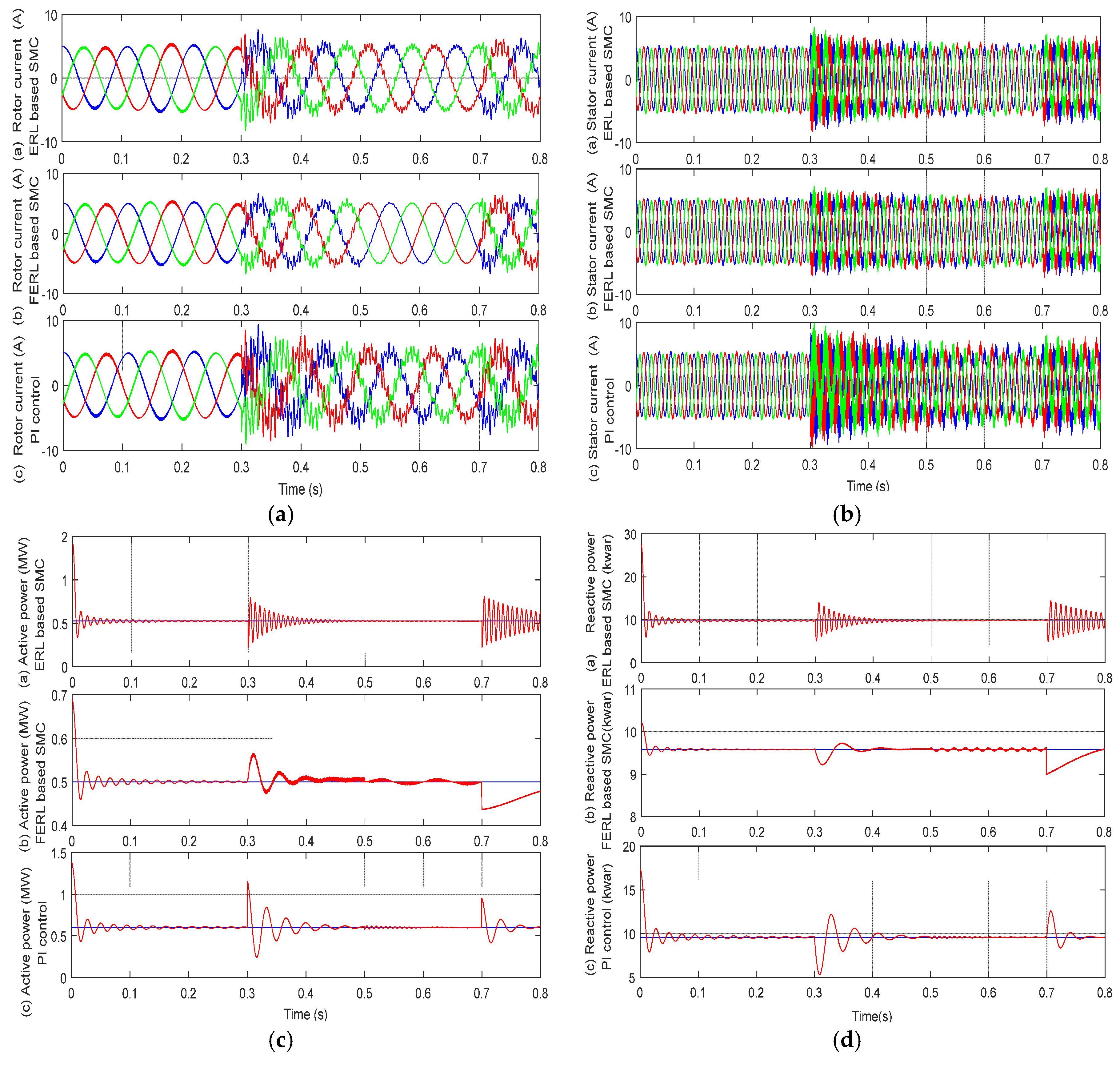

Figure 10.
Variable wind speed curve.
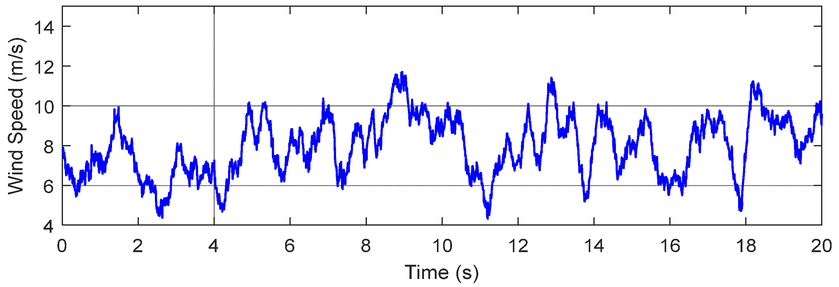
Figure 11.
Simulation results under variable wind speed comparing three different approaches: (a) generator speed (b) active power tracking; (c) DC-link voltage.
Figure 11.
Simulation results under variable wind speed comparing three different approaches: (a) generator speed (b) active power tracking; (c) DC-link voltage.

Figure 12.
Integral square error (ISE) indices in different time periods.
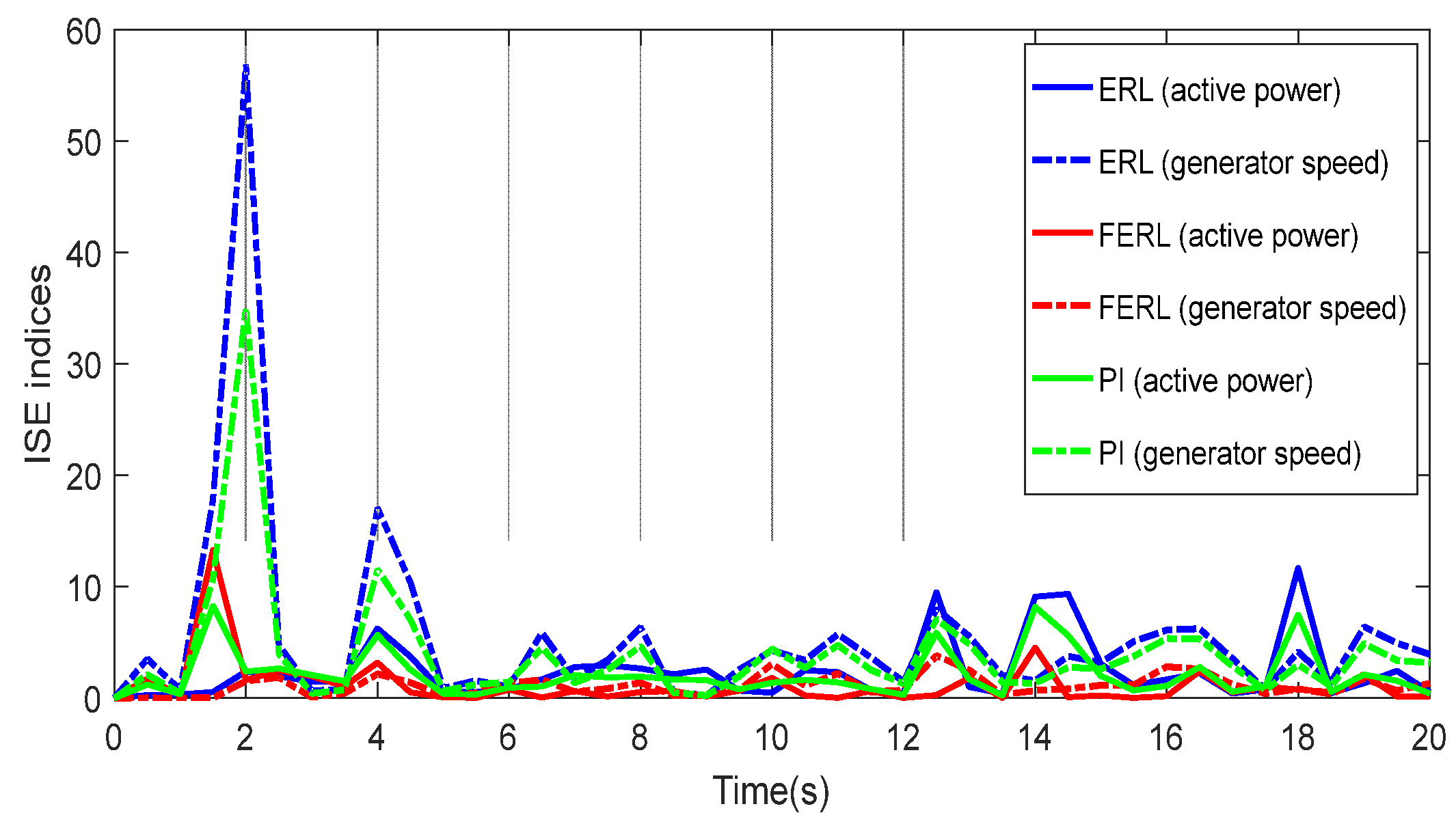
Figure 13.
Experimental test bed.
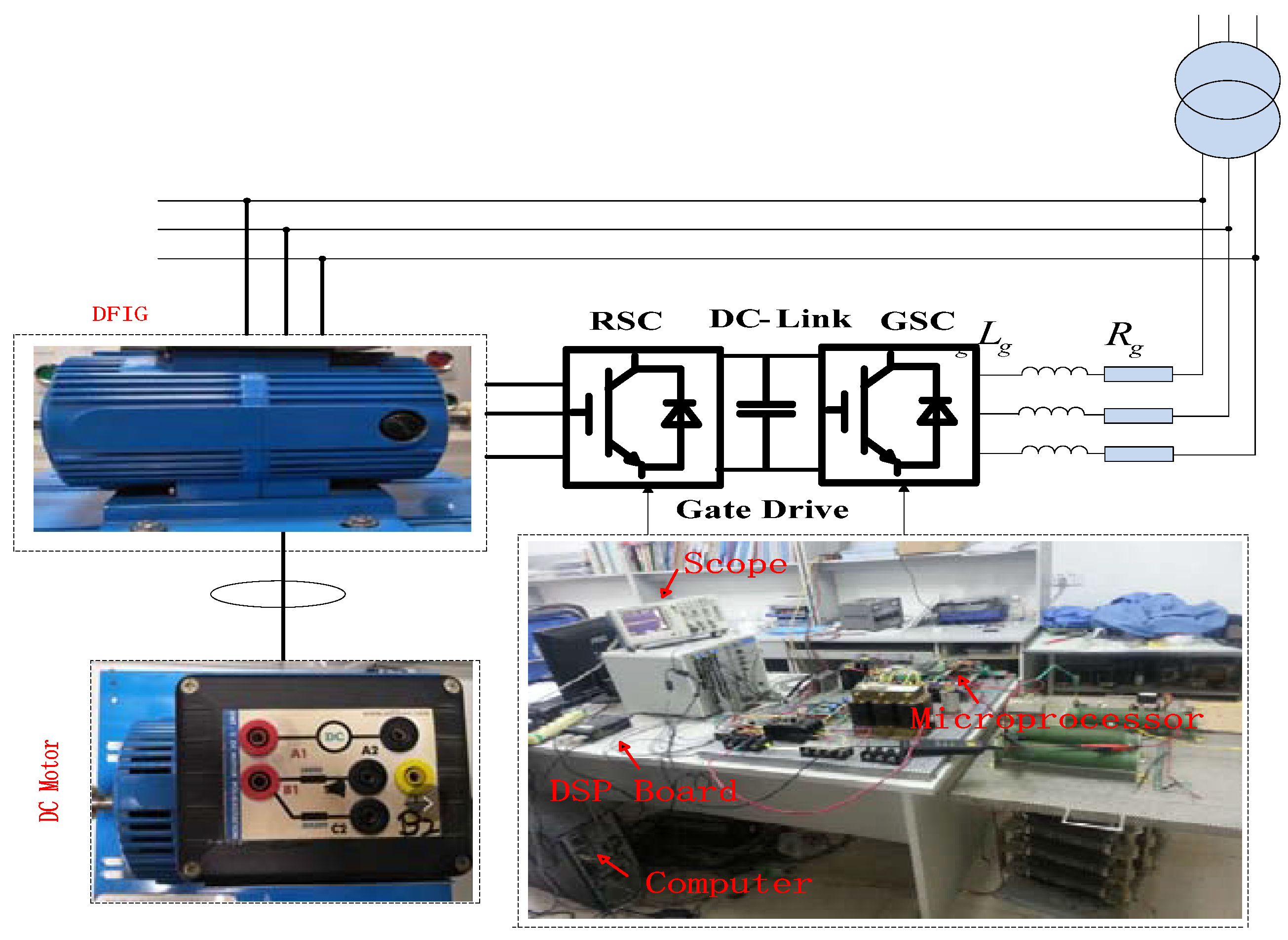
Figure 14.
Experimental results under variable wind speed comparing three different approaches: (a) generator speed (b) active power tracking; (c) DC-link voltage; (d) grid-side currents.
Figure 14.
Experimental results under variable wind speed comparing three different approaches: (a) generator speed (b) active power tracking; (c) DC-link voltage; (d) grid-side currents.

Table 1.
DFIG Generator Parameters.
| Parameters | Value |
|---|---|
| Rated power | 2 MW |
| Rated DC-link voltage | 1200 V |
| Stator voltage | 690 V |
| Stator frequency | 50 Hz |
| 0.0108 pu/0.0121 pu | |
| 3.362 pu | |
| 0.102 pu/0.11 pu | |
| Lumped inertia constant | 0.5 s |
| Stator/rotor turns ratio | 0.333 |
© 2017 by the authors. Licensee MDPI, Basel, Switzerland. This article is an open access article distributed under the terms and conditions of the Creative Commons Attribution (CC BY) license (http://creativecommons.org/licenses/by/4.0/).
Share and Cite
MDPI and ACS Style
Xiong, L.; Li, P.; Li, H.; Wang, J. Sliding Mode Control of DFIG Wind Turbines with a Fast Exponential Reaching Law. Energies 2017, 10, 1788. https://doi.org/10.3390/en10111788
AMA Style
Xiong L, Li P, Li H, Wang J. Sliding Mode Control of DFIG Wind Turbines with a Fast Exponential Reaching Law. Energies. 2017; 10(11):1788. https://doi.org/10.3390/en10111788
Chicago/Turabian StyleXiong, Linyun, Penghan Li, Hao Li, and Jie Wang. 2017. "Sliding Mode Control of DFIG Wind Turbines with a Fast Exponential Reaching Law" Energies 10, no. 11: 1788. https://doi.org/10.3390/en10111788
Note that from the first issue of 2016, this journal uses article numbers instead of page numbers. See further details here.