Regenerative Intelligent Brake Control for Electric Motorcycles
by
 , ,
, ,
Juan Jesús Castillo Aguilar
* ,
,
Javier Pérez Fernández
 ,
,
Juan María Velasco García
and
Juan Antonio Cabrera Carrillo
Department of Mechanical Engineering, University of Málaga, 29071 Málaga, Spain
*
Author to whom correspondence should be addressed.
Energies 2017, 10(10), 1648; https://doi.org/10.3390/en10101648
Submission received: 17 August 2017
/
Revised: 22 September 2017
/
Accepted: 13 October 2017
/
Published: 20 October 2017
(This article belongs to the Special Issue Methods to Improve Energy Use in Road Vehicles)
Abstract
:Vehicle models whose propulsion system is based on electric motors are increasing in number within the automobile industry. They will soon become a reliable alternative to vehicles with conventional propulsion systems. The main advantages of this type of vehicles are the non-emission of polluting gases and noise and the effectiveness of electric motors compared to combustion engines. Some of the disadvantages that electric vehicle manufacturers still have to solve are their low autonomy due to inefficient energy storage systems, vehicle cost, which is still too high, and reducing the recharging time. Current regenerative systems in motorcycles are designed with a low fixed maximum regeneration rate in order not to cause the rear wheel to slip when braking with the regenerative brake no matter what the road condition is. These types of systems do not make use of all the available regeneration power, since more importance is placed on safety when braking. An optimized regenerative braking strategy for two-wheeled vehicles is described is this work. This system is designed to recover the maximum energy in braking processes while maintaining the vehicle’s stability. In order to develop the previously described regenerative control, tyre forces, vehicle speed and road adhesion are obtained by means of an estimation algorithm. A based-on-fuzzy-logic algorithm is programmed to carry out an optimized control with this information. This system recuperates maximum braking power without compromising the rear wheel slip and safety. Simulations show that the system optimizes energy regeneration on every surface compared to a constant regeneration strategy.
1. Introduction
A large number of countries are adopting policies to increase the number of electric vehicles in their fleets. The aim of these policies is to improve air quality by reducing pollutant emissions, especially in urban areas [1]. In this environment, the relationship between braking time and the vehicle moving time is very high. This indicates that there is a large amount of energy wasted as heat. This wasted kinetic energy can be recovered in electric vehicles by means of a regenerative braking system [2,3,4]. In large cities, with frequent stops and intersections, the energy dissipated in braking can reach 34% of total traction energy [3]. In traditional vehicles, that energy is wasted as heat through the brake friction. For this reason, regeneration or energy recovery systems are being widely used in electric vehicles.
Electric vehicles have the ability to easily implement traction and/or braking control systems on the drive wheels. Since the motor is already part of the system, it is only necessary to implement a minimum of software and hardware to control that torque in the wheel. The great advantage is that electric motors can also be used as power generators. When a positive torque is required, the motor consumes battery power and when a negative torque is applied, motor power is delivered to the batteries. Nowadays, traction and braking controls are widely implemented in vehicles, with the aim of reducing braking distance or providing better manoeuvrability in emergency situations. Some of these systems are the Antilock Brake System (ABS) or the Traction Control System (TCS). These systems have evolved from their origin, using increasingly sophisticated algorithms and complex control architectures. Fuzzy logic [5,6], sliding control [7,8,9], control by artificial neural networks [10,11] and nonlinear control [12,13] are examples of the most used control methods. These systems try to optimize the longitudinal and lateral force in the tire, obtaining the maximum available force in the wheel-road contact during braking and traction processes.
At present, regeneration systems in commercial electric vehicles do not take advantage of the characteristics mentioned above. A maximum level of regeneration is fixed for safety or battery capacity reasons. Therefore, they do not take advantage of the maximum available longitudinal force in tire-road contact. This way, these systems do not get the highest possible regenerated energy.
In addition, most of the research on regeneration systems has focused on four-wheeled vehicles, although some authors have addressed this issue for two-wheeled vehicles. Most of them only deal with the electrical part of the system and do not take into account vehicle-road interaction [14,15,16,17]. Robinson and Singh [18] developed a control technique that applies a braking torque to the rear wheel, regenerating that braking energy from the rear wheel to the battery system. Moreover, the system controls the slip to prevent the locking of the rear wheel during braking. Lin et al. [19] studied an ABS braking control for electric scooters based on regenerative braking.
In this work the design of a regenerative braking system for electric motorcycles is carried out using control and estimation of the road adherence algorithms. The system recovers the maximum energy during the braking process with the rear wheel of the motorcycle, always guaranteeing the safety of the rider thanks to the incorporation of a wheel slip control system. As we have mentioned, both energy saving and safety are fundamental subjects of study in vehicles. The system proposed here aims to improve the safety of electric vehicles as well as save energy in a novel way. It makes use of a fuzzy control that estimates the road adhesion and determines the optimal regenerative braking torque without causing the wheel to slip. The proposed system will reduce the use of the traditional rear friction brake depending on road conditions thanks to the high braking torque that can be achieved with the electric motor.
This article begins with the description of the dynamic model of the electric motor used for simulation in Section 2. The method to estimate the speed of the vehicle as well as the detection of the type of road is included in Section 3. The regenerative control system is described in Section 4. The performance of the whole system is verified through simulations included in Section 5. Finally, the conclusions are presented in Section 6.
2. Electric Motor Model
Modelling of the electric motor is required to know the torque on the rear wheel. The model is used in the simulations of the regeneration system.
Our prototype motorcycle has a Permanent Magnet Alternate Current (PMAC) motor, which is powered by a controller. This controller is also powered from the battery system. The battery system is able to absorb the energy recovered during the regeneration. In our case, the maximum current regenerated by the system is limited to 150 A to prevent heating of the batteries. The maximum torque that can be applied is 80 Nm. The curve relating the torque to the angular speed of rotation of the motor is shown in Figure 1. These curves have been obtained by means of a dynamometric test by varying the angular speed of the motor and the position of the accelerator. As shown in Figure 1, a negative torque that brakes the vehicle is applied to the rear wheel of the motorcycle when the motor is in regeneration mode.
As it can be seen, the curves are proportional to the Throttle or Regeneration Rate (TR). In this paper, TR = [−1, 1], where −1 means 100% regeneration and 1 means 100% acceleration. Previous curves have been modelled using a Look-up table. The rear wheel torque is obtained by means of the following expression:
where T is the torque on the rear wheel, is the transmission ratio between the motor and the rear wheel, ωm is the angular speed of the motor, TR is the Throttle or Regeneration rate and f(·) is the adjustment function of the look-up table.
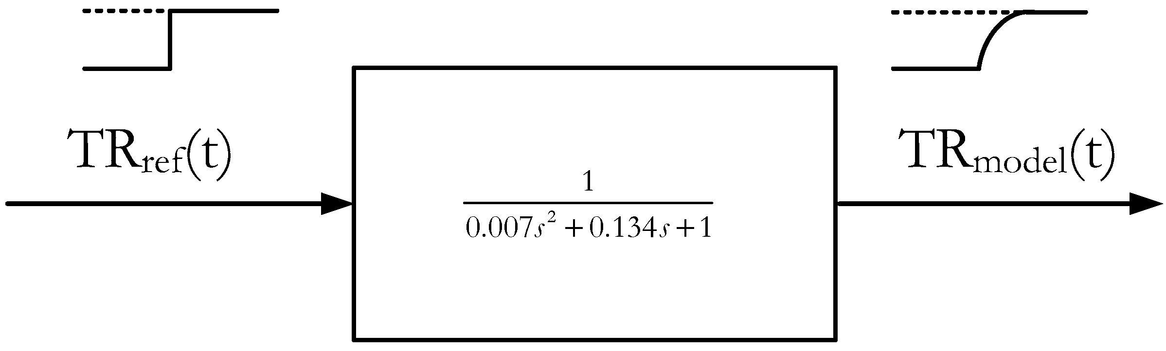
The controller installed on the electric motorcycle has been modelled using a step input (Figure 2). The response is approximated to a second order system according to the expression shown in the figure.
The actual responses of the motor have been compared to the programmed model. Two step inputs have been used. The results are shown in Figure 3. As it can be seen, the model response matches with measured one appropriately.
3. Estimation of Road Type and Vehicle Parameters
The slip on each of the wheels is used to determine the road type. The slip is defined with the following equation in the case of braking:
where ω is the angular velocity of the wheel, r the radius of the tire and vx the longitudinal velocity of the vehicle.
An Extended Kalman Filter (EKF) [5] based on a model that simulates the straight line behavior of the motorcycle is used in order to determine the speed of the vehicle. This model is described next.
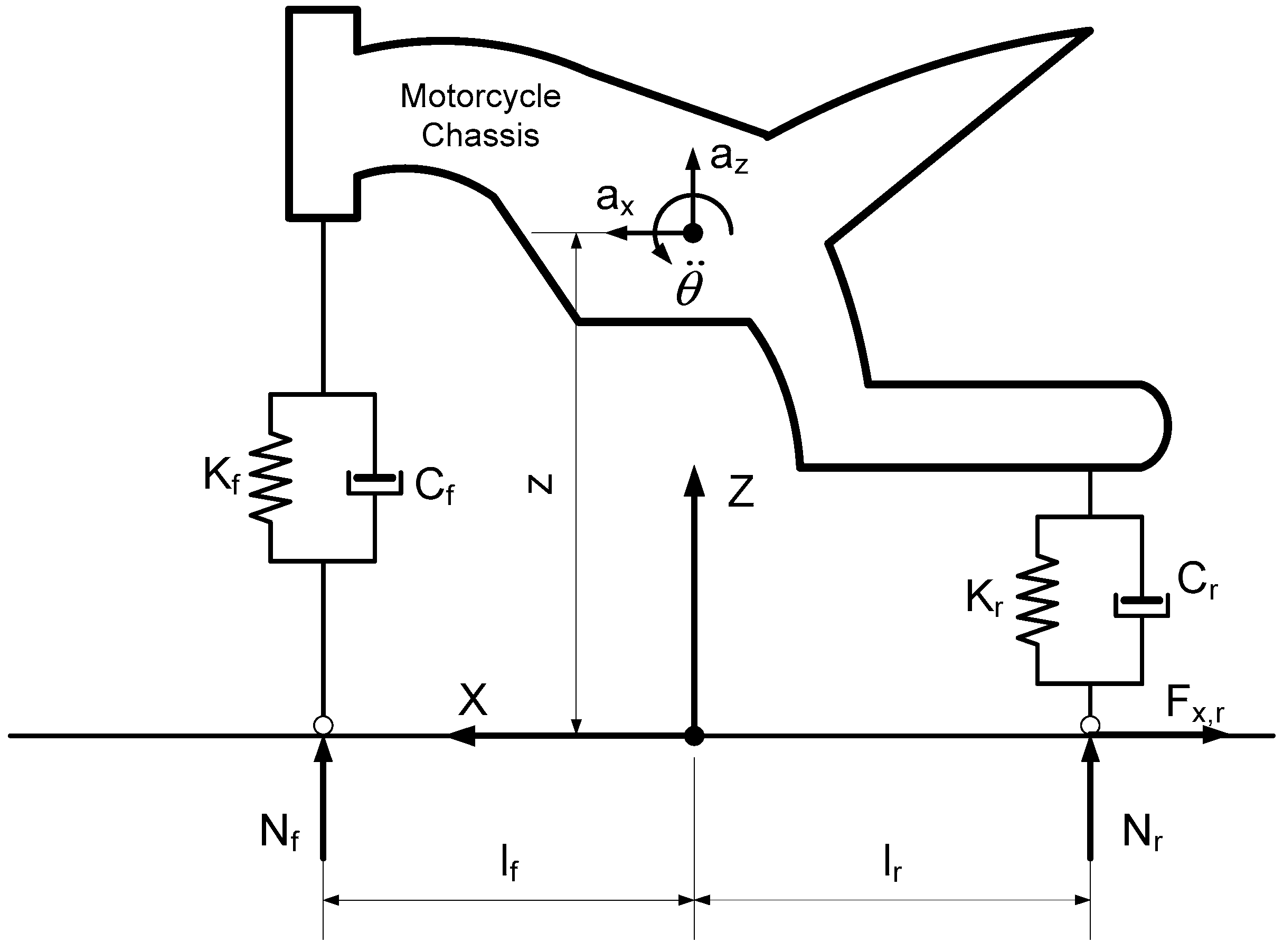
In Figure 4 the basic geometry of a motorcycle is represented schematically. The equations that govern the dynamics of the vehicle are:
The equations defining the front and rear suspensions can be simplified as:
The parameters and variables used in this model are shown in Table 1.
The control model to be used in this work is shown in Figure 5.
As it can be seen, the regeneration control block (4) has the optimum slip (sopt) as input. Optimum slip is defined as the slip value that produces the maximum longitudinal force during braking or traction. This is the desired slip for the motorcycle to have the highest regeneration rate. In addition, control block 4 also has the current slip (s) on the rear wheel of the motorcycle as input. The output of this block is the throttle or regeneration rate. In our case, this rate is an input to the motor of the motorcycle.
A parameter estimation algorithm is needed to obtain the inputs to the regeneration control, since these cannot be measured with sensors in the vehicle. This is carried out in blocks (2) and (3) of Figure 5.
The linear speed of the motorcycle, the longitudinal force and the coefficient of friction in the rear wheel are estimated first. To this end, an Extended Kalman filter as proposed in [5] is used.
The EKF is defined according to the following equations:
where wk and vk represent the noise of the model and the measures respectively, xk is the state vector and jk is the measurement vector. The state vector is:
and the measurement vector is:
A first order random walk is used to estimate the longitudinal and vertical forces. Therefore, the model equations are included next:
Finally, the measurement equations are the following:
The EKF algorithm estimates the longitudinal and vertical forces and the longitudinal speed of the motorcycle in addition to the rear wheel torque with the equations developed above.
An estimate of the slip and the coefficient of friction can be made according to the following equations:
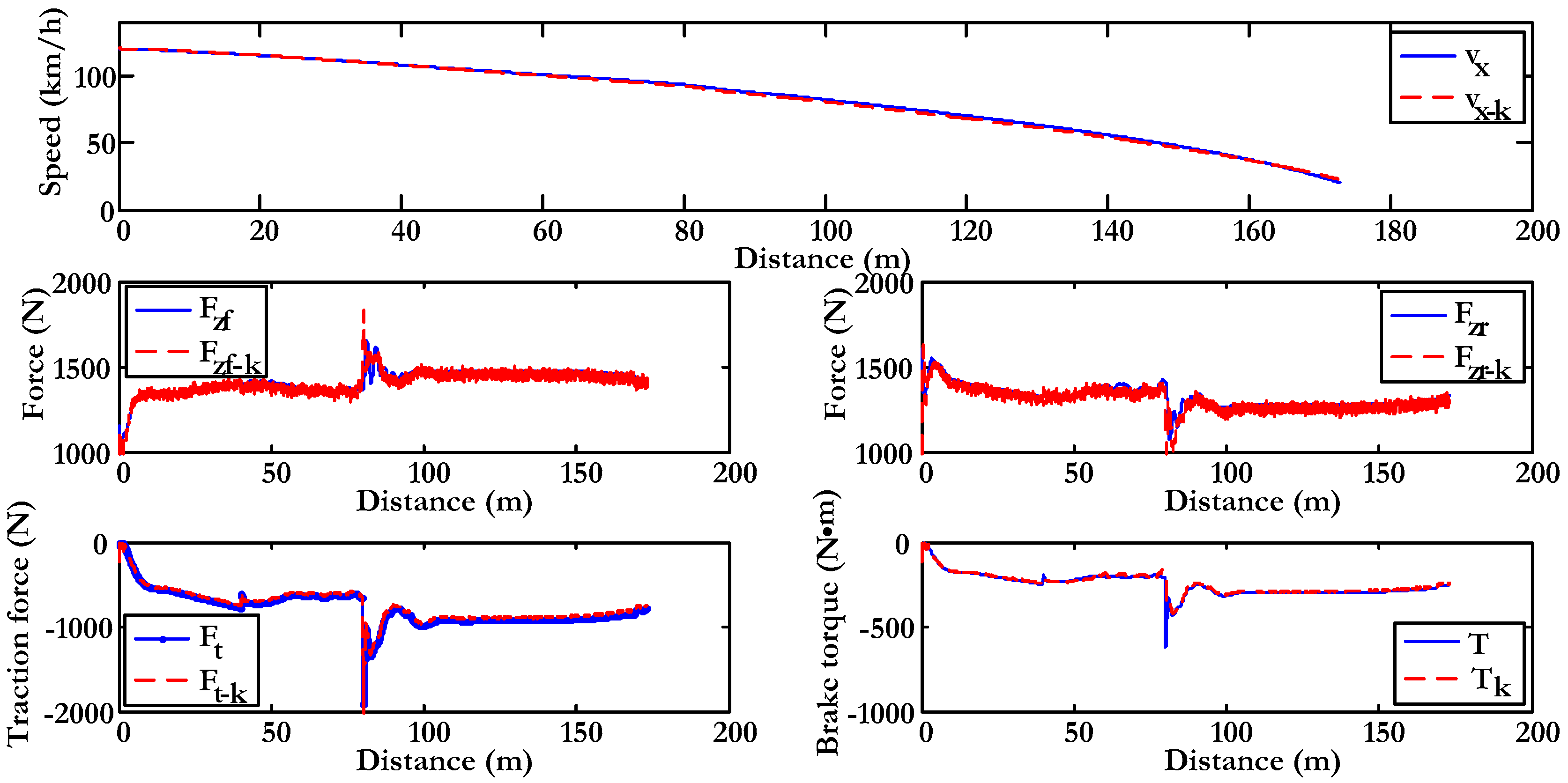
Figure 6 shows, by way of example, a simulation performed with BikeSim® (Ann Arbor, MI, USA) where the parameters necessary for the determination of the slip and the coefficient of adhesion are estimated. The test consists of the following sections: 40 m of high adhesion surface, 40 m of low adhesion surface and a third section with high adhesion again. The initial speed is 120 km/h. In these simulations the signal from the sensors has been altered with zero-mean random noise. A subscript “k” in the legend indicates that it is an estimated magnitude. The parameters estimated by means of the EKF fit quite accurately to the values provided by the simulation software. It can be verified that the speed (vx), front vertical force (Fzf), rear vertical force (Fzr), rear traction force (Ft) and brake torque (T) are estimated correctly.
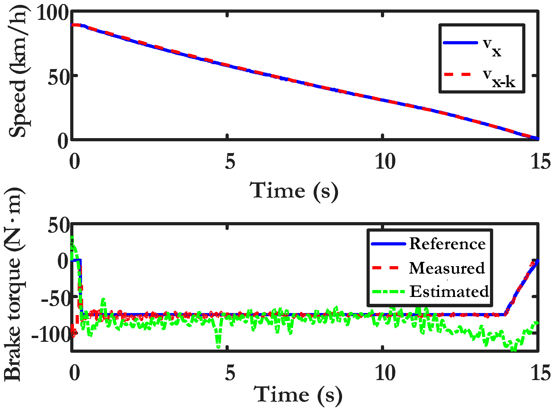
Finally, the following figure shows the results obtained in a real test carried out with the vehicle described in Appendix A. This estimation algorithm verification test was performed with a 20% constant regeneration rate. Figure 7 includes the actual speed (vx), measured by a high frequency Global Positioning System-based speed sensors and the measured brake torque. It can be seen that the speed is perfectly estimated. The brake torque is also correctly estimated except in the final part of the test, where a higher error is observed.
These values are used to determine the road type and to obtain the optimal slip, as shown in Figure 8. A control based on fuzzy logic is programmed to estimate the road type. The ouput of this block is an index called Road Condition Index (RCI), related to the adherence of the road. Finally, the optimal slip is obtained through a Neural Network.
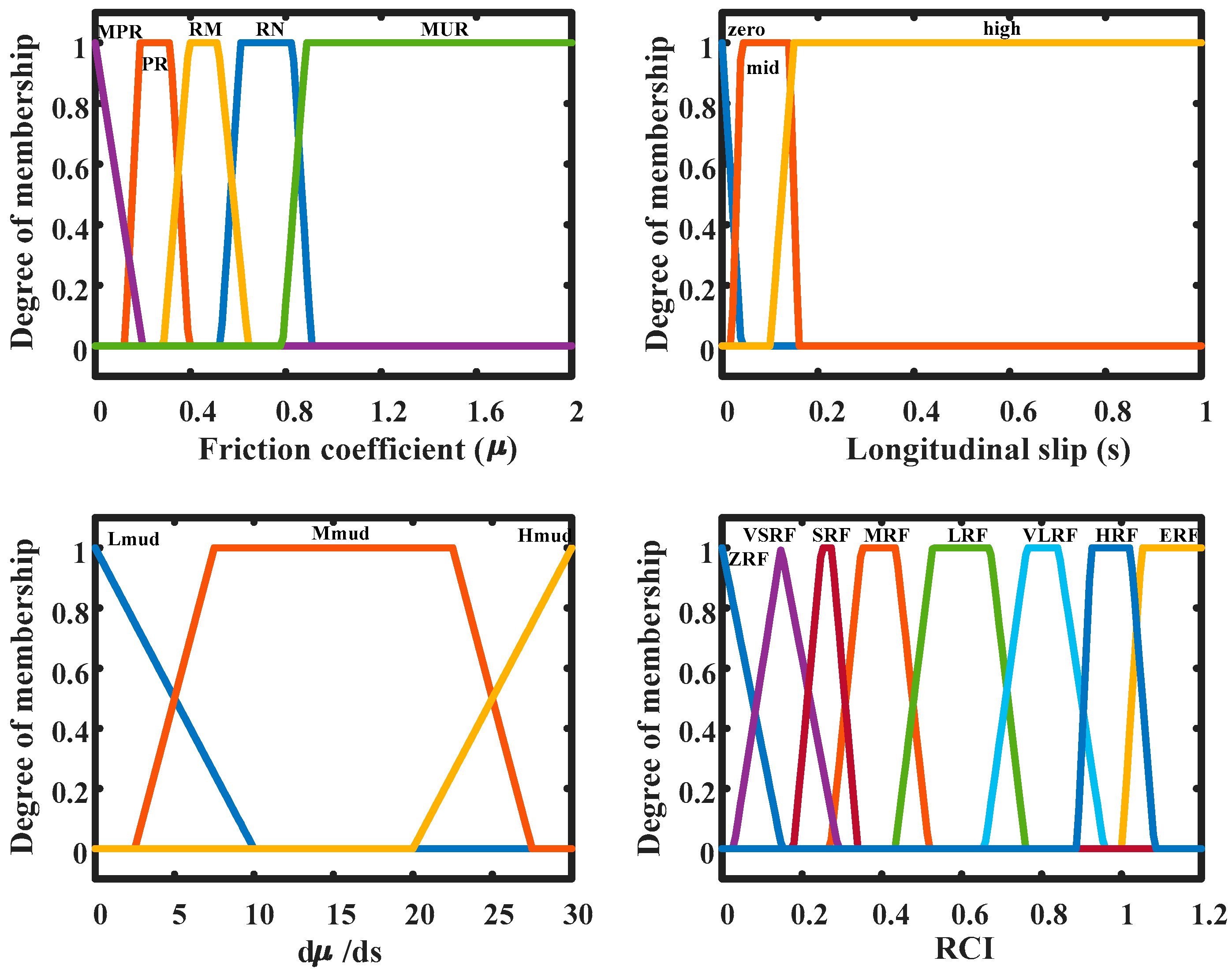
The road type estimation block has the slip (s), the longitudinal coefficient of friction (μ) and the variation of the longitudinal coefficient with respect to the slip (dμ/ds) as input. It produces an output value indicating the type of road on which the vehicle circulates. This value is within the range (0–1.2), where 1.2 represents a road with the highest coefficient of adhesion and 0 represents the lowest one.
The input and output variables have been fuzzyfied by means of the membership functions indicated in Figure 9. In addition, the rules defined for the fuzzy control are presented in Table 2.
Finally, as shown in Figure 8, once the road type has been obtained by the RCI index, the optimum slip is calculated. In this work, the optimum slip has been estimated by means of a trained neural network using the Burkhardt model [20]. The network has the RCI index, obtained from the fuzzy block, and the wheel slip angle as inputs. The net provides the optimum slip for each surface from these inputs. In our case, the slip angle has been taken as null.
4. Regenerative Control
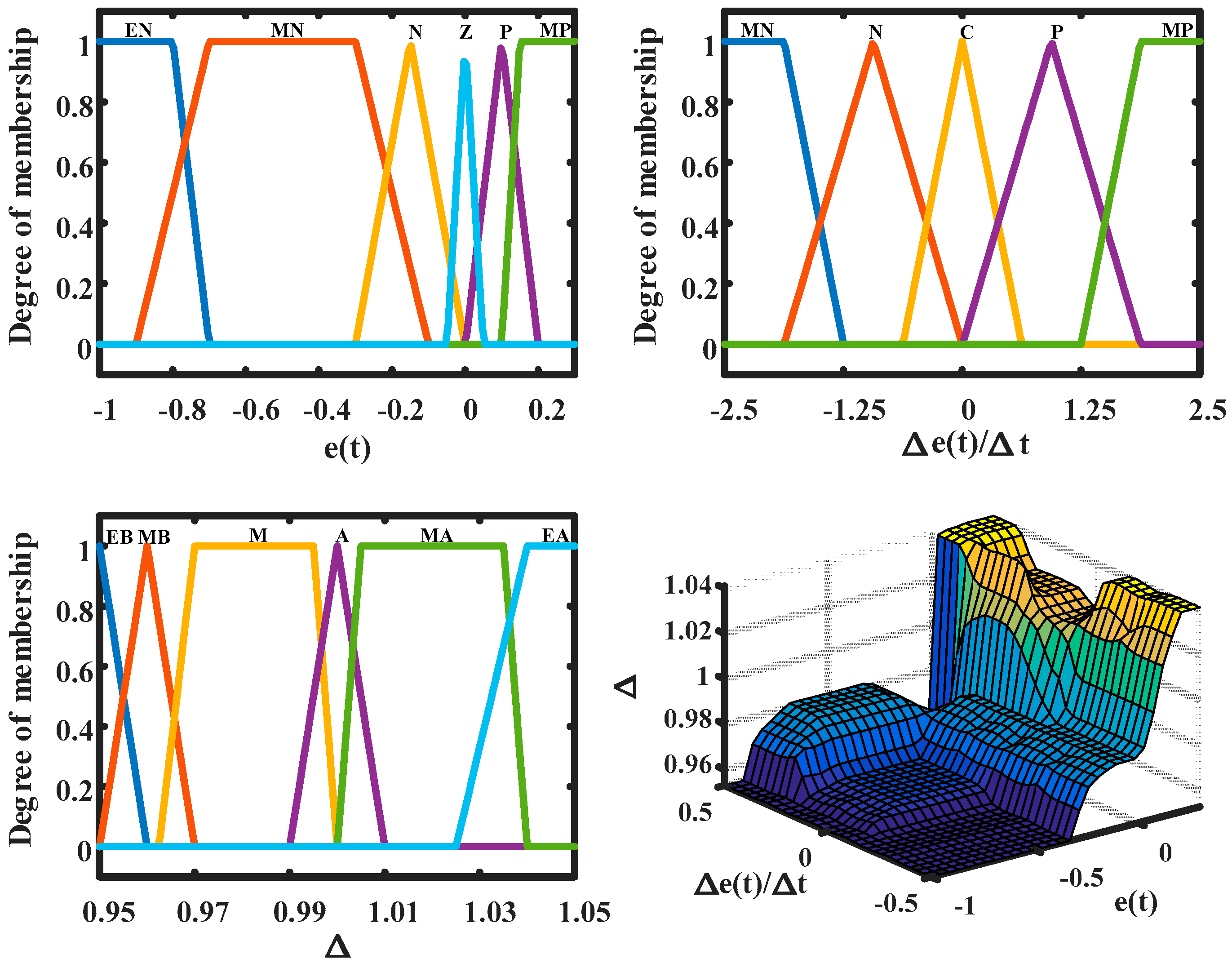
The last step in the control scheme is to obtain the level of regeneration that is desired in order to obtain the maximum energy recovered in the braking processes. To this end, a control based on fuzzy logic has been developed (Figure 10). This fuzzy block has the slip error and the variation of the error in time as inputs, which are defined as:
As it can be seen, the slip error is defined as the difference between the optimal slip and the actual slip at each instant of time. Once the error and the error variation have been calculated, the percentage of regeneration to be applied according to the next block is obtained. The output variable of the fuzzy block, called Δ, is a multiplying factor of the regeneration rate established in the previous time interval. Thus, the rate at time t is obtained from:
The regeneration rate can never be less than a certain minimum value. This is so because if a null value were reached at an instant of time, the system would not be able to raise the rate again. On the other hand, the rate can never exceed a maximum value. This maximum value is imposed by the maximum bearable charge current of the battery system.
5. Simulations
The vehicle dynamics simulation software BikeSim® was used for this purpose. Simulations were carried out on Simulink® (Natick, MA, USA), using BikeSim® as S-function. BikeSim® was incorporated to the model to simulate vehicle behaviour. The model has the outputs from the control system as inputs and provided the measures obtained in the vehicle. These simulations allow evaluating the potential and feasibility of the proposed regeneration algorithm. Table 3 shows the main characteristics of the vehicle used in the simulations.
5.1. Low Adhesion Condition Simulation
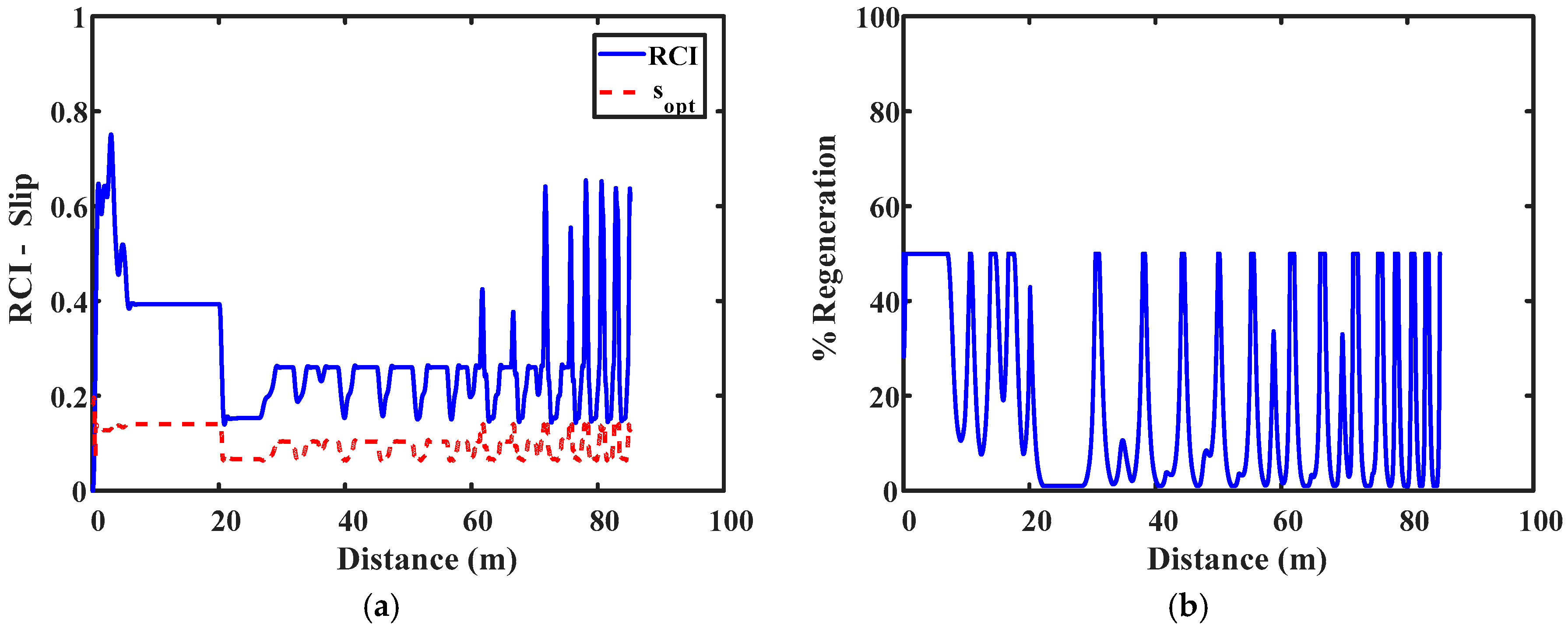
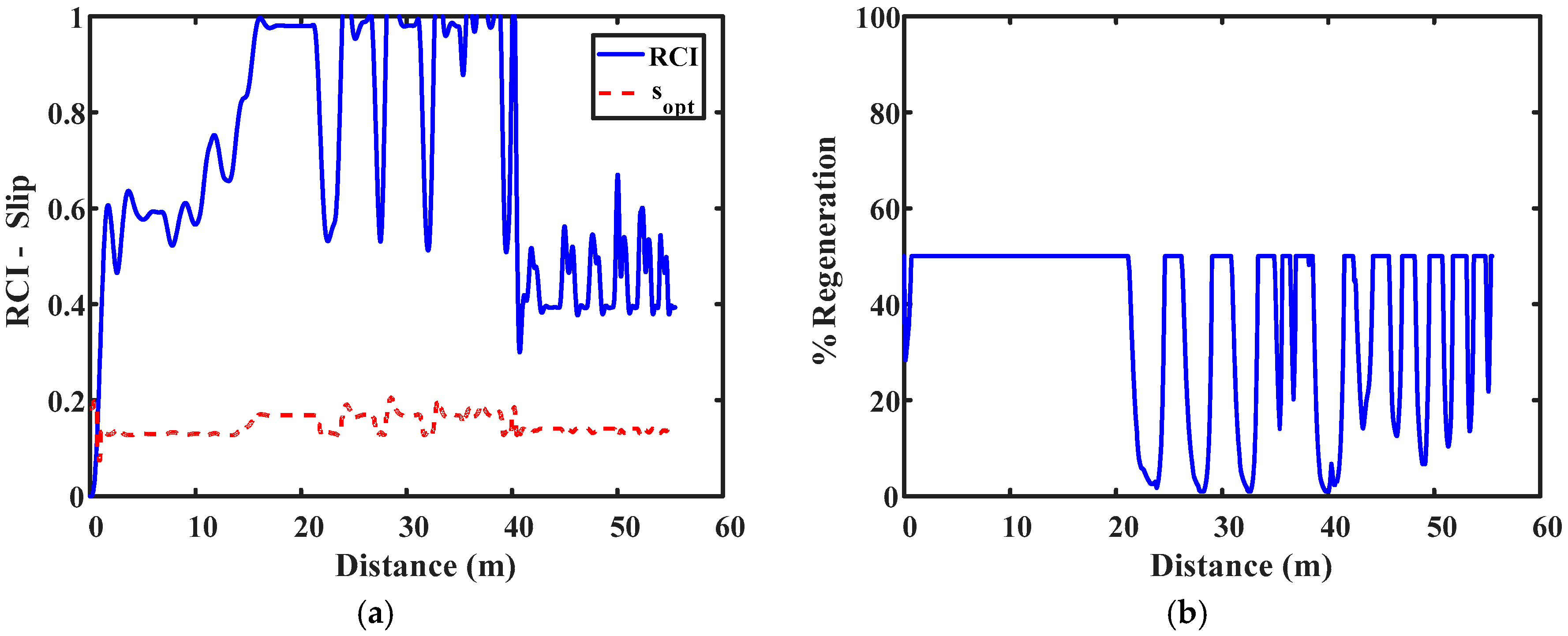
In the first place, a transition between a low adhesion and a very low adhesion surface has been simulated. The test begins at the low adhesion surface. After 20 m the surface is changed to a very low adhesion surface. The initial speed is 60 km/h. The test ends when the motorcycle reaches 20 km/h. Maximum regeneration has been limited to 50%. This rate of regeneration corresponds to an intensity of 148 A, less than 150 A of the maximum charge current recommended by the battery manufacturer.
In Figure 11a, the output provided by the road estimation algorithm and the neural network can be observed. The system is able to detect the change of surface and adapt the optimum slip to the new conditions.
The output of the fuzzy block that provides the regeneration rate is shown in Figure 11b. It can be verified how, when changing surface, the system adapts the rate in order to obtain the maximum possible regeneration on each surface.
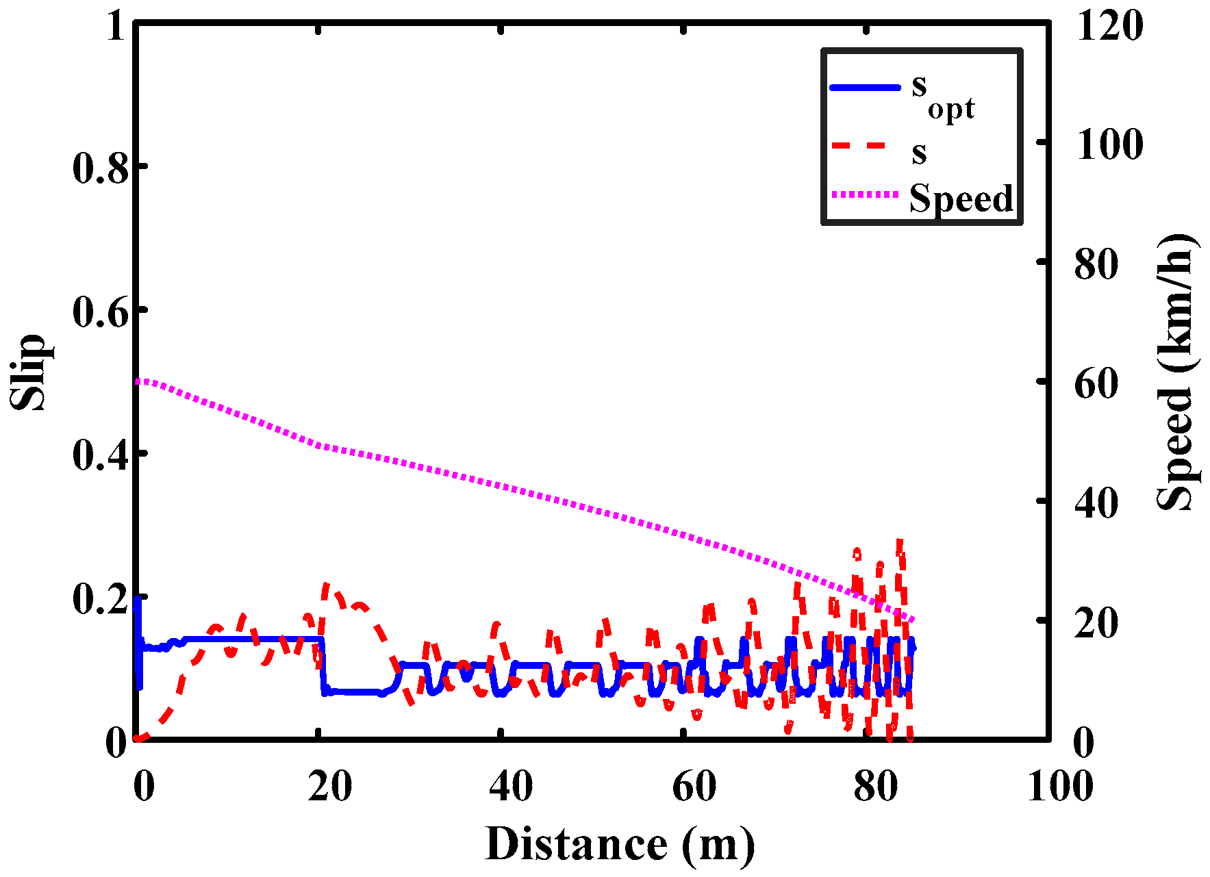
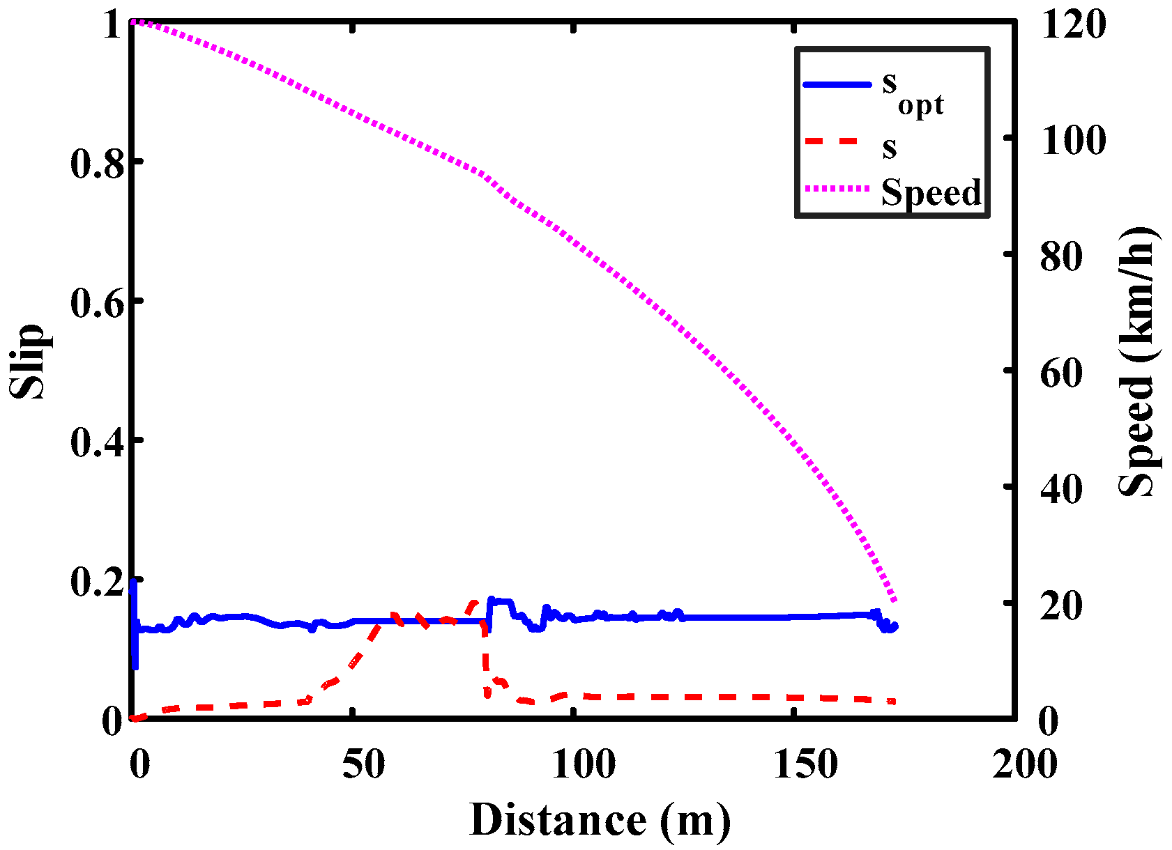
Finally, the slip and velocity evolution throughout the test is shown in Figure 12. The slip tends to reach the optimum slip, adapting its value after the change of surface.
5.2. High to Low Adhesion Transition Simulation
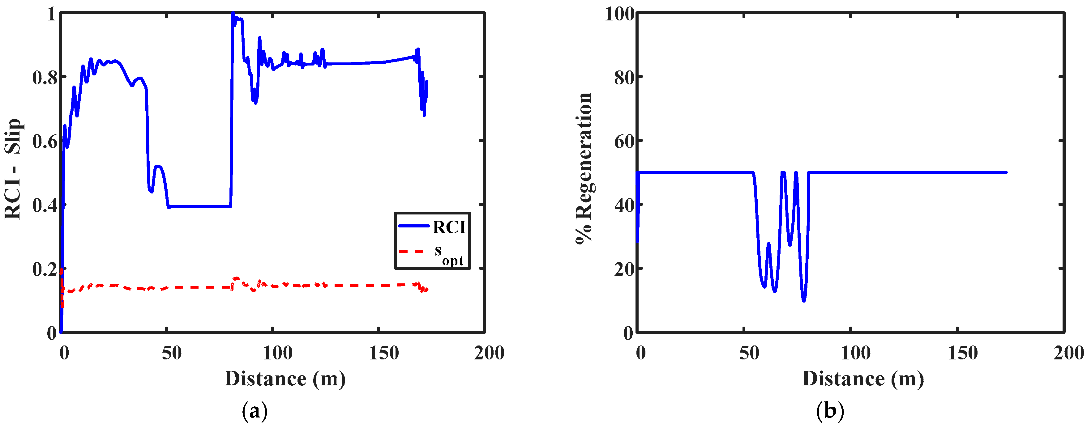
Secondly, a transition between a high adhesion surface and a low adhesion surface has been simulated. The test consists of the following sections: 40 m of high adhesion surface, 40 m of low adhesion surface and a third section with high adhesion again. The initial speed is 120 km/h. Figure 13a shows the type of surface and the optimal slip. As in the previous case, the estimation algorithms quickly detect surface changes.
Figure 13b shows the output of the fuzzy block which provides the regeneration rate. It is observed that the rate of regeneration is maintained at the maximum in the high adhesion surface. This is due to the fact that, even with that regeneration percentage, a slip in the rear axle close to the optimum slip is not achieved. Once the low adhesion surface has been reached, the regeneration rate decreases in order to adjust the slip to the new adhesion conditions (Figure 14).
5.3. Controls Comparison
Simulations have been carried out to verify that the new control manages to optimize regenerated energy. For this purpose, tests in which the vehicle starts at a speed of 80 km/h have been carried out. The test lasts five seconds. At the end of that time, the velocity achieved and the energy recovered are determined (Table 4). The constant regeneration rate has been set at 10%.
It is observed how the proposed control recovers more energy in all cases. This difference becomes more evident the greater the adhesion of the surface is. With low adhesion the difference is less because the optimal rate is very close to the 10% established as a constant. In addition, the proposed control does not lead to the blocking of the wheels under any circumstances.
5.4. Regenerative vs. Conventional Brake Comparison
Finally, emergency braking processes have been simulated. The following simulations allow evaluating the viability of substituting the conventional rear friction brake with the regenerative brake. The first test consists of the following sections: 40 m of high adhesion surface and 40 m of low adhesion surface. The initial speed is 120 km/h. The test is similar to the previous cases except that, in this case, the front brake is also being actuated. The pressure in the front axle is controlled by an anti-lock system with slip and wheel angular speed control. The proposed system detects the change in the adhesion conditions (Figure 15a), adapting the regeneration rate to the adhesion conditions of each road (Figure 15b). The regeneration rate is kept at its maximum value on the high adhesion surface. In this zone, the slip on the rear wheels approaches the optimal slip slowly. Once in the low adhesion surface, the regeneration rate is changed to adapt the slip to the optimal one provided by the estimation algorithm (Figure 16).
Two additional simulations have been conducted. The initial and final speeds are 80 and 20 km/h respectively in both cases. In the first case, an emergency braking is conducted on a high adhesion surface. The rear brake torque is generated with a conventional ABS and with the regenerative brake system (REG). Results are shown in Figure 17a. It can be seen that the brake distance is lower when the vehicle is equipped with the conventional ABS system. This is due to the fact that the regeneration rate is limited to 50%. With this maximum rate, the regenerative brake torque cannot brake as efficiently as the conventional system does. Similarly, a second test is has been simulated on a low adhesion surface (see Figure 17b). In this condition, the regenerative brake can produce enough brake torque to cause the rear wheel to reach the optimal slip. Under these circumstances, the regenerative brake decelerates the vehicle faster than the conventional ABS systems thanks to a better control of the rear wheel slip.
Finally, Table 5 summarizes the results obtained in the previous tests. The last column also includes the results of tests in which the maximum regeneration rate has been increased to 80%. The regenerative control performs better on the low adhesion surface due to a better and more stable control of the rear wheel slip. On the contrary, the regenerative control in which the regeneration rate is limited to 50% cannot substitute the conventional brake on high adhesion roads since the brake distance and deceleration are worse. However, if the maximum regeneration rate is increased, the regenerative brake can generate a higher rear brake torque, which makes it perform better than the conventional brake.
These simulations show that the proposed system can be installed in a real vehicle to cooperate with or in substitution of the conventional friction brake. The system could control the slip no matter which surface the vehicle is moving on if the maximum regeneration rate were increased. However, batteries with a higher admissible charge current or ultracapacitors are necessary if the maximum regeneration rate is increased [14,16].
6. Conclusions
Algorithms for the estimation of parameters and the control necessary to optimize the regeneration in two-wheeled vehicles have been developed in this paper. The parameter estimation is necessary to be able to determine the speed of the vehicle and the road adhesion conditions. The control algorithm allows one, once the previous data is known, to optimize the rate of regeneration in the rear wheel of a motorcycle. Generally, regeneration in two-wheeled vehicles is usually limited to a minimum value, around 5–10% of motor power. This pursues two objectives: on one hand, to limit the charge current in the battery to protect it. Secondly, the possibility of locking the rear wheel in any adhesion condition is reduced. If this occurs, ABS control is required.
With the proposal developed in this work, the rate of regeneration on any surface is optimized, blocking the wheel is prevented by always working in the vicinity of the optimal slip. Protection of the battery is achieved by limiting the intensity in those cases in which the regeneration could exceed a value of risk for its integrity. Simulations show that the system optimizes the regeneration rate on every surface and that the energy recovered surpasses the one obtained with constant regeneration rates.
Finally, despite the fact that this paper is mainly focused on recovering the maximum energy with the regenerative brake, we have shown that the regenerative brake could substitute the rear friction brake provided higher regeneration rates can be achieved. High regeneration rates require batteries with a higher admissible charge current or ultracapacitors on vehicles. However, there is still a great deal of research to be carried out. Experimental tests have to be carried out to verify the aptitude of this proposal, especially in high adherence conditions. The work reported here is exploratory. Future works will include tests on different surfaces, with different maneuvers and with higher regeneration rates.
Acknowledgments
This work is partly supported by the Ministry of Economy, Industry and Competitiveness under grant TRA2015-67920-R and partly by the University of Málaga.
Author Contributions
Juan Jesús Castillo Aguilar performed the simulations and conceived and designed the experiments. Javier Pérez Fernández and Juan María Velasco García performed most experiments and measurements and contributed to the programming of the estimations algorithm. Juan Antonio Cabrera Carrillo wrote the introduction, helped to analyse the data and provided some useful suggestions in the writing and revision of the text.
Conflicts of Interest
The authors declare no conflict of interest.
Appendix A. Experimental Vehicle
The motorcycle used in the tests is shown below. The table includes the main characteristics of the vehicle.


| Component | Parameter | Description |
|---|---|---|
| Vehicle | Motorcycle weight | 135 Kg |
| Chassis Type | Steel Tubular | |
| Height of gravity centre | 621 mm | |
| Distance between axis | 1370 mm | |
| Wheel radius | 300 mm | |
| Distance from the COG to the front axle | 670 mm | |
| Front tire | 95/70 R 17 | |
| Rear tire | 115/70 R 17 | |
| Electric motor | Brand | Heinzmann PMS 150 |
| Type | Axial Flux Permanent Magnet | |
| Maximum speed | 6000 rpm | |
| Maximum torque | 80 Nm | |
| Torque constant (Km) | 0.145 Nm/A | |
| Maximum power | 34.1 KW (46.36 CV) | |
| Battery | Battery Type | LiPo |
| Cell layout | 26S5P | |
| Total capacity | 4.8 KWh | |
| Rated Voltage | 96 V | |
| Maximum discharge current | 1250 A | |
| Maximum load current | 300 A |
References
- Ferrero, E.; Alessandrini, S.; Balanzino, A. Impact of the electric vehicles on the air pollution from a highway. Appl. Energy 2016, 169, 450–459. [Google Scholar] [CrossRef]
- Ye, M.; Bai, Z.F.; Cao, B.G. Energy recovery for battery electric vehicles. Proc. Inst. Mech. Eng. Part D J. Automob. Eng. 2008, 222, 1827–1839. [Google Scholar] [CrossRef]
- Tehrani, M.; Hairi-Yazdi, R.; Haghpanah-Jahromi, B.; Esfahanian, V.; Amiri, M.; Jafari, R. Design of an anti-lock regenerative braking system for a series hybrid electric vehicle. Int. J. Automot. Eng. 2011, 1, 16–20. [Google Scholar]
- Gao, Y.; Chen, L.; Ehsani, M. Investigation of the effectiveness of regenerative braking for EV and HEV. SAE Tech. Pap. 1999. [Google Scholar] [CrossRef]
- Cabrera, J.A.; Castillo, J.J.; Carabias, E.; Ortiz, A. Evolutionary Optimization of a Motorcycle Traction Control System Based on Fuzzy Logic. IEEE Trans. Fuzzy Syst. 2015, 23, 1594–1607. [Google Scholar] [CrossRef]
- Lin, H.; Song, C. Design of a fuzzy logic controller for ABS of Electric Vehicle based on AMESim and Simulink. In Proceedings of the 2011 International Conference on Transportation, Mechanical, and Electrical Engineering (TMEE), Changchun, China, 16–18 December 2011; pp. 779–782. [Google Scholar]
- Choi, S.; Cho, D.W. Design of Nonlinear Sliding Mode Controller with Pulse Width Modulation for Vehicular Slip Ratio Control. Veh. Syst. Dyn. 2011, 36, 57–72. [Google Scholar] [CrossRef]
- Harifi, A.; Aghagolzadeh, A.; Alizadeh, G.; Sadeghi, M. Designing a sliding mode controller for slip control of antilock brake systems. Transp. Res. Part C 2008, 16, 731–741. [Google Scholar] [CrossRef]
- Habibi, M.; Yazdizadeh, A. A novel Fuzzy-Sliding Mode Controller for Antilock Braking System. In Proceedings of the 2010 2nd International Conference on Advanced Computer Control (ICACC), Shenyang, China, 27–29 March 2010; Volume 4, pp. 110–114. [Google Scholar]
- Topalov, A.; Oniz, Y.; Kayacan, E.; Kaynak, O. Neuro-fuzzy control of antilock braking system using sliding mode incremental learning algorithm. Neurocomputing 2011, 74, 1883–1893. [Google Scholar] [CrossRef]
- Cirovic, V.; Aleksendric, D.; Mladenovic, D. Braking torque control using recurrent neural networks. Proc. Inst. Mech. Eng. Part D J. Automob. Eng. 2012, 226, 754–766. [Google Scholar] [CrossRef]
- Gerard, M.; Pasillas-Lépine, W.; de Vries, E.; Verhaegen, M.; Cho, D.W. Improvements to a five-phase ABS algorithm for experimental validation. Veh. Syst. Dyn. 2012, 50, 1585–1611. [Google Scholar] [CrossRef]
- Tanelli, M.; Astolfi, A.; Savaresi, S. Robust nonlinear output feedback control for brake by wire control systems. Automatica 2008, 44, 1078–1087. [Google Scholar] [CrossRef]
- Sun, L. Systematic experimental evaluation of a novel regenerative braking system on DC motor drive using super-capacitors. In Proceedings of the 2014 IEEE Conference and Expo Transportation Electrification Asia-Pacific (ITEC Asia-Pacific), Beijing, China, 31 August–3 September 2014; pp. 1–6. [Google Scholar]
- Guarisco, M.; Bouriot, B.; Ravey, A.; Bouquain, D. Powertrain energy management for Hybrid Electric Scooter. In Proceedings of the 2014 IEEE Transportation Electrification Conference and Expo (ITEC), Dearborn, NI, USA, 15–18 June 2014; pp. 1–4. [Google Scholar]
- Andorinha, N.; Sousa, S.; Antunes, V. A new control method of an electric scooter with a hybrid ultracapacitor/battery energy storage topology. In Proceedings of the 2nd Experiment@ International Conference (exp.at’13), Coimbra, Portugal, 18–20 September 2013; pp. 11–16. [Google Scholar]
- Lai, Y.S.; Lin, Y.K. Design and implementation of digital-controlled bi-directional converter for scooter applications. In Proceedings of the 2013 IEEE 10th International Conference on Power Electronics and Drive Systems (PEDS), Kitakyushu, Japan, 22–25 April 2013; pp. 271–276. [Google Scholar]
- Robinson, J.; Singh, T. eABS: Regenerative Anti-Lock Braking for Electric Motorcycles. SAE Int. J. Passeng. Cars Mech. Syst. 2013, 6, 1484–1492. [Google Scholar] [CrossRef]
- Lin, W.C.; Lin, C.L.; Hsu, P.M.; Wu, M.T. Realization of anti-lock braking strategy for electric scooters. IEEE Trans. Ind. Electron. 2014, 61, 2826–2833. [Google Scholar] [CrossRef]
- Castillo, J.J.; Cabrera, J.A.; Guerra, A.J.; Simón, A. A Novel Electrohydraulic Brake System with Tire–Road Friction Estimation and Continuous Brake Pressure Control. IEEE Trans. Ind. Electron. 2016, 63, 1863–1875. [Google Scholar] [CrossRef]
Figure 1.
Torque curves of the electric motor.
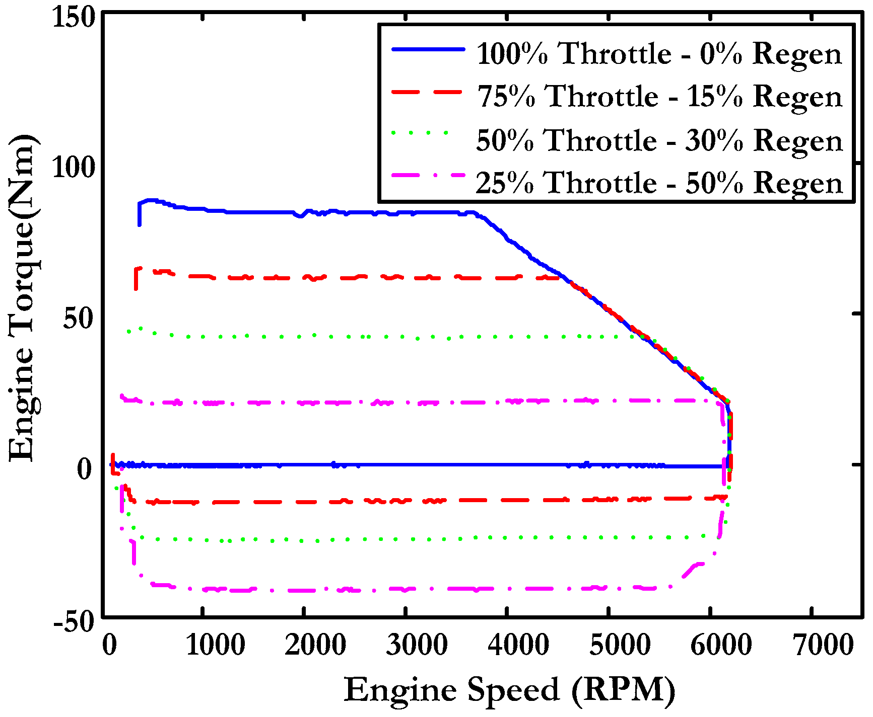
Figure 2.
Second order response model of the electric motor.

Figure 3.
Real and simulated response to step input.
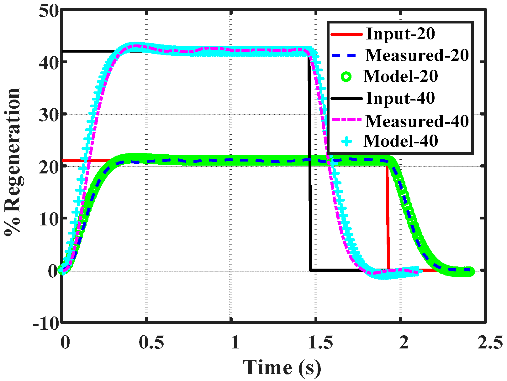
Figure 4.
Simplified motorcycle model.

Figure 5.
Motorcycle regenerative control scheme.
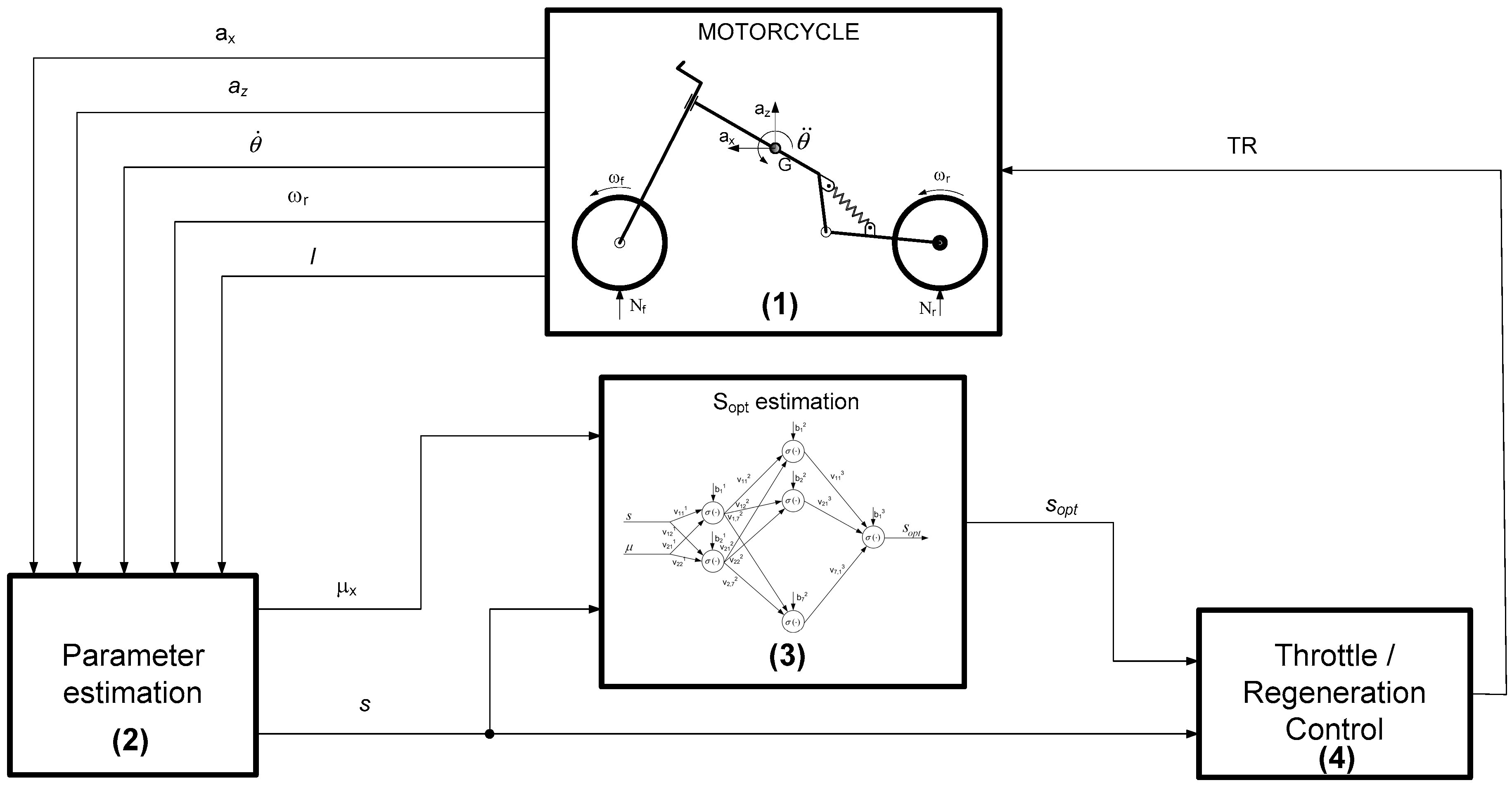
Figure 6.
Estimation of speed, tractor effort and vertical forces.

Figure 7.
Estimation of speed and brake torque.

Figure 8.
Control of road type and estimation of optimum slip.
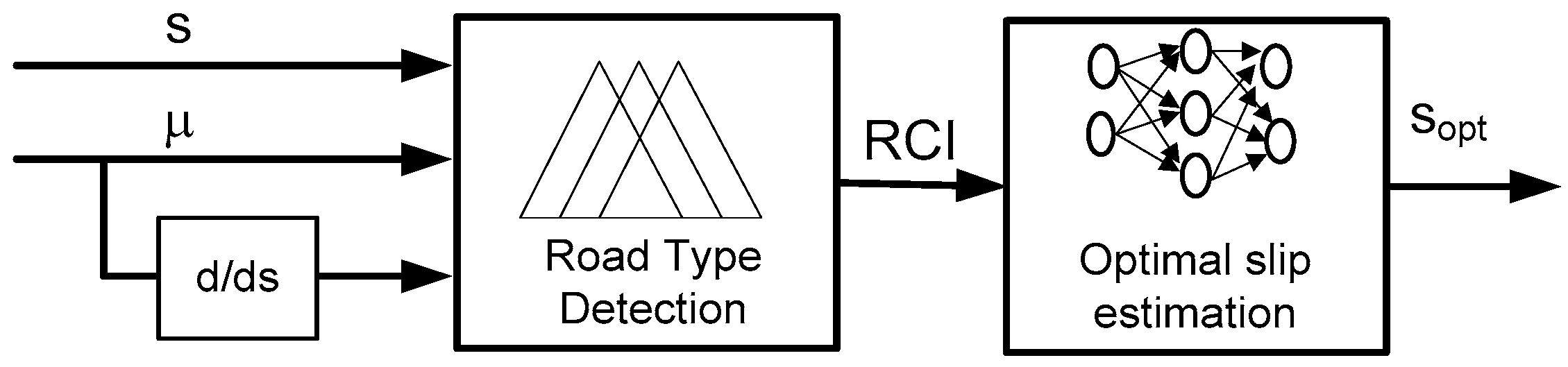
Figure 9.
Membership functions for input and output variables of the road type detection block.

Figure 10.
Membership functions for the input and output variables of the regeneration rate block.

Figure 11.
Estimation of road type and optimum slip (a) and regeneration rate (b).

Figure 12.
Optimum slip, real slip and speed.

Figure 13.
Estimation of road type and optimum slip (a) and regeneration rate (b).

Figure 14.
Optimum slip, real slip and speed.

Figure 15.
Estimation of road type and optimum slip (a) and regeneration rate (b).

Figure 16.
Optimum slip, real slip and speed.
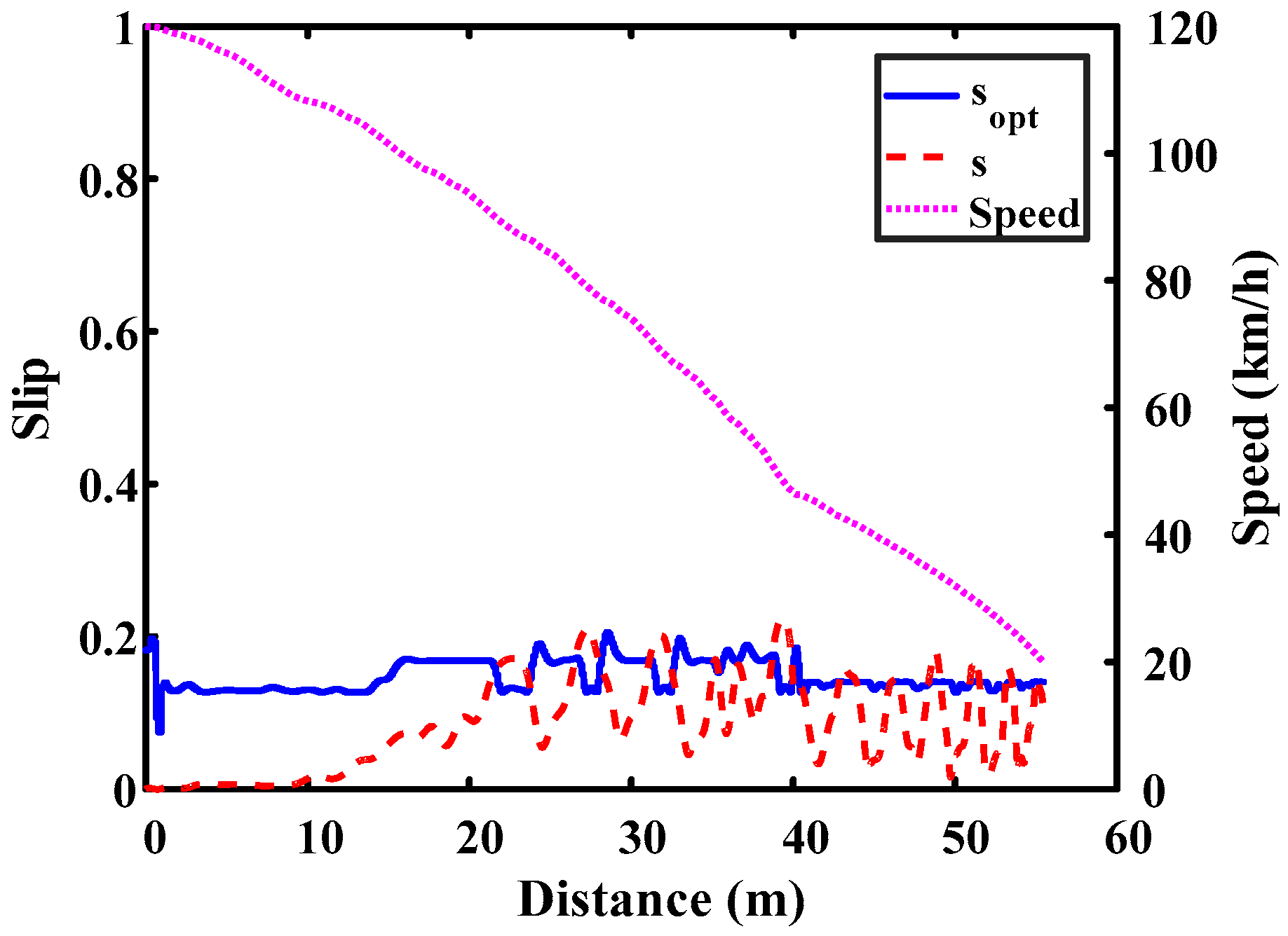
Figure 17.
Slip and vehicle speed. High adhesion surface (a); Low adhesion surface (b).
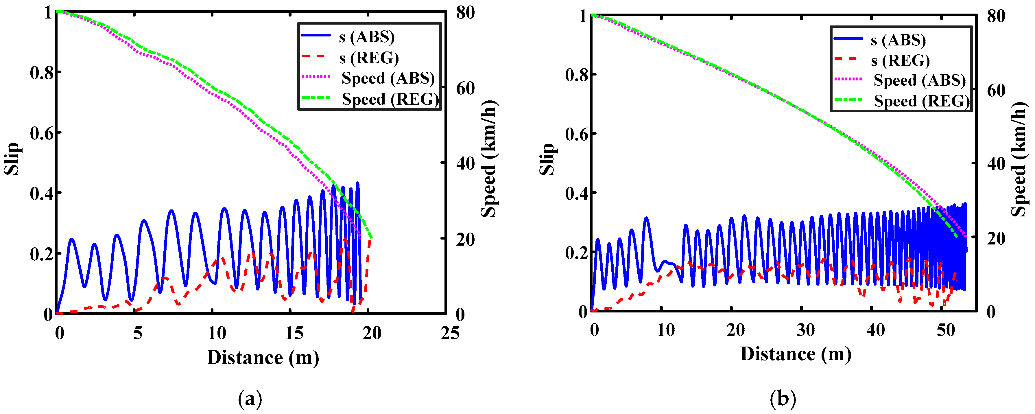
Table 1.
Motorcycle model parameters.
| Description | Description | ||
|---|---|---|---|
| M | Mass | J | Moment of inertia of the wheel |
| ax | Longitudinal acceleration | Iy | Inertia on the Y axis |
| az | Vertical Acceleration | Nf | Normal front force |
| x | Longitudinal displacement | Nr | Normal rear force |
| z | Vertical displacement | lf | Front half length |
| θ | Pitch angle | lr | Rear half-length |
| Rr | Rear tire radius | kf | Stiffness of front suspension |
| T | Torque applied on rear wheel | kr | Stiffness of rear suspension |
| C | Aerodynamic coefficient | cf | Front Damping |
| Fxr | Longitudinal rear wheel force | cr | Rear damping |
| ωr | Rear wheel angular speed | L0 | Suspension length |
| Km | Torque-Intensity Ratio | I | Intensity |
Table 2.
Road control rules.
| Rule Number | Friction Coefficient | Slip | dμ/ds | RCI |
|---|---|---|---|---|
| 1 | MPR | mid | --- | VSRF |
| 2 | MPR | high | --- | ZRF |
| 3 | MPR | zero | Lmud | MRF |
| 4 | MPR | zero | Mmud | LRF |
| 5 | MPR | zero | Hmud | LRF |
| 6 | PR | mid | --- | SRF |
| 7 | PR | high | --- | VSRF |
| 8 | PR | zero | Lmud | LRF |
| 9 | PR | zero | Mmud | LRF |
| 10 | PR | zero | Hmud | VLRF |
| 11 | RM | mid | --- | MRF |
| 12 | RM | high | --- | MRF |
| 13 | RM | zero | Lmud | LRF |
| 14 | RM | zero | Mmud | VLRF |
| 15 | RM | zero | Hmud | HRF |
| 16 | RN | mid | --- | VLRF |
| 17 | RN | high | --- | LRF |
| 18 | RN | zero | Lmud | VLRF |
| 19 | RN | zero | Mmud | HRF |
| 20 | RN | zero | Hmud | ERF |
| 21 | MUR | mid | --- | HRF |
| 22 | MUR | high | --- | ERF |
| 23 | MUR | zero | Lmud | HRF |
| 24 | MUR | zero | Mmud | ERF |
| 25 | MUR | zero | Hmud | ERF |
Table 3.
Motorcycle model parameters.
| Description Value | |
|---|---|
| Total mass | 275 kg |
| Wheel radius | 0.32 m |
| Moment of inertia of the wheel | 0.484 kg·m2 |
| Distance from the COG * to the front axle | 0.86 m |
| Distance from the COG * to the rear axle | 0.67 m |
| Height of gravity centre | 0.4 m |
| Front area | 0.6 m2 |
| Aerodynamic coefficient | 0.55 |
| Motor-wheel transmission ratio | 1:6.4 |
* COG = Centre of Gravity.
Table 4.
Comparison of controls.
| Surface/Control | Vo (km/h) | Vf (km/h) | Energy (Wh) |
|---|---|---|---|
| High adhesion/Regen. cte. (10%) | 80 | 55.52 | 4.53 |
| High adhesion/Controlled regeneration | 80 | 22.4 | 15.93 |
| Medium adhesion/Regen. cte. (10%) | 80 | 55.54 | 4.53 |
| Medium adhesion/Controlled regeneration | 80 | 36.5 | 11.37 |
| Low adhesion/Regen. cte. (10%) | 80 | 55.54 | 4.53 |
| Low adhesion/Controlled regeneration | 80 | 56.1 | 4.54 |
Table 5.
Comparison ABS vs. Regenerative braking.
| Surface | Control | ABS | Regenerative Reg. Max. = 50% | Regenerative Reg. Max. = 80% |
|---|---|---|---|---|
| High adhesion | Time (s) | 1.39 | 1.42 | 1.40 |
| Distance (m) | 19.54 | 20.24 | 20.85 | |
| Mean deceleration (m/s2) | 11.95 | 11.71 | 11.86 | |
| Low adhesion | Time (s) | 3.90 | 3.76 | 3.80 |
| Distance (m) | 53.51 | 52.19 | 52.62 | |
| Mean deceleration (m/s2) | 4.27 | 4.44 | 4.38 |
© 2017 by the authors. Licensee MDPI, Basel, Switzerland. This article is an open access article distributed under the terms and conditions of the Creative Commons Attribution (CC BY) license (http://creativecommons.org/licenses/by/4.0/).
Share and Cite
MDPI and ACS Style
Castillo Aguilar, J.J.; Pérez Fernández, J.; Velasco García, J.M.; Cabrera Carrillo, J.A. Regenerative Intelligent Brake Control for Electric Motorcycles. Energies 2017, 10, 1648. https://doi.org/10.3390/en10101648
AMA Style
Castillo Aguilar JJ, Pérez Fernández J, Velasco García JM, Cabrera Carrillo JA. Regenerative Intelligent Brake Control for Electric Motorcycles. Energies. 2017; 10(10):1648. https://doi.org/10.3390/en10101648
Chicago/Turabian StyleCastillo Aguilar, Juan Jesús, Javier Pérez Fernández, Juan María Velasco García, and Juan Antonio Cabrera Carrillo. 2017. "Regenerative Intelligent Brake Control for Electric Motorcycles" Energies 10, no. 10: 1648. https://doi.org/10.3390/en10101648
Note that from the first issue of 2016, this journal uses article numbers instead of page numbers. See further details here.