Ride Comfort Optimization of In-Wheel-Motor Electric Vehicles with In-Wheel Vibration Absorbers


1
School of Mechatronics Engineering, Nanchang University, Nanchang 330031, China
2
School of Automotive Engineering, Jilin University, Jilin 130022, China
*
Author to whom correspondence should be addressed.
Energies 2017, 10(10), 1647; https://doi.org/10.3390/en10101647
Submission received: 20 September 2017
/
Revised: 12 October 2017
/
Accepted: 17 October 2017
/
Published: 19 October 2017
(This article belongs to the Special Issue The International Symposium on Electric Vehicles (ISEV2017))
Abstract
:This paper presents an in-wheel vibration absorber for in-wheel-motor electric vehicles (IWM EVs), and a corresponding control strategy to improve vehicle ride comfort. The proposed in-wheel vibration absorber, designed for suppressing the motor vibrations, is composed of a spring, an annular rubber bushing, and a controllable damper. The parameters of the in-wheel spring and rubber bushing are determined by an improved particle swarm optimization (IPSO) algorithm, which is executed under the typical driving conditions and can absorb vibration passively. To deal with negative interaction effects between vehicle suspension and in-wheel absorber, a linear quadratic regulator (LQR) algorithm is developed to control suspension damper, and meanwhile a fuzzy proportional-integral-derivative (PID) method is developed to control in-wheel damper as well. Through four evaluation indexes, i.e., vehicle body vertical acceleration, suspension dynamic deflection, wheel dynamic load, and motor wallop, simulation results show that, compared to the conventional electric wheel, the proposed suspension LQR control effectively improves vehicle ride comfort, and the in-wheel absorber exhibits excellent performance in terms of wheel and motor vibration suppression.
1. Introduction
In recent years, to solve the challenges resulting from the increasing energy crisis and environmental pollution, the electric vehicles (EVs) have been widely developed as an essential part of future efficient and green transportation plans. Being different from the traditional EVs with centralized powertrains, the in-wheel-motor (IWM) EVs feature electric motors mounted in the wheel hubs. By replacing the mechanical transmission system with an independent and direct drive system, IWMEVs have great potential to achieve better dynamic control, smaller space utilization, higher driving efficiency, and redundant driving system, etc. [1,2,3], so as to improve overall vehicle performance. As an ideal carrier for advanced vehicle dynamics control system, IWMEVs have played a significant role in defining the development direction for the next generation EVs. Nevertheless, challenges, such as vehicle ride comfort, still remain with IWMEVs due to the heavy electric wheels. As a matter of fact, the unsprung mass with the IWMs usually results in harsh vertical negative effects, such as reduction of vehicle ride comfort [4,5,6], deterioration of road friendliness [7], invalidation of suspension control methods [8], and reduction of motor reliability under the large wallop [9,10,11], which have greatly restricted the practical development of IWMEVs.
For vehicles with a centralized powertrain, the unsprung mass is relatively small, and therefore vehicle comfort is mainly determined by suspension performance, while for IWMEVs, the wheel is an integrated system composed of tire, motor, brakes, etc. When road vibration acts on the wheel, the tire and motor are directly impacted. It is worth noting that the huge wallop can cause relative radial motion between the stator and rotor of the electric motor, which can deteriorate its performance and eventually shorten its service life [12]. Additionally, the vibration in the electric wheel is coupled with that of the vehicle body, leading to complicated vehicle dynamics characteristics.
In order to improve IWMEVs’ ride comfort, intensive research activities have focused on the suppression of vertical negative effects. A rich literature has contributed to several solutions, such as motor weight reduction, unsprung mass transfer, and optimization of vibration transmission, etc.
The use of lightweight motors is an effective approach for reducing electric wheel mass. The axial flux motor, featured with high torque density, power density, and reduced cogging effect [13,14], meets most of electrical requirements and physical limits for EV applications. More importantly, it naturally matches the shape and dimension of the classical-vehicle wheel rim so that it can be readily applied in electric wheels. Nikam et al. [15] designed a permanent magnet brushless DC motor with a segmented rotor type construction for IWMEVs, in which, the concentrated winding method is adopted to minimize end-winding effects and to reduce copper loss and motor weight. Takahashi et al. [16] presented a ferrite permanent magnet-based low cost in-wheel axial gap motor design. To further reduce the size and weight, an open slot structure was used instead of a semi-closed slot structure. Experimental results showed that the semi-closed slot structure was more effective to achieve size and weight reduction. However, light weight motors have not been widely applied because of material performance and manufacturing cost issues.
Alternatively, the IWM can be transferred to the sprung mass as a vibration absorber by utilizing a suspended device, which is beneficial to improve vehicle ride comfort within a wide range of frequencies. Bridgestone Corporation [17] developed an electric wheel with a dynamic vibration absorber, which controls the negative effects on the vertical vibration by utilizing the motor mass as the absorber. Shao et al. [18] designed a dynamic-damping in-wheel-motor driven system, where the suspended motor functioned as a dynamic absorber and a fault-tolerant fuzzy approach was utilized to control the active suspension of the IWMEV. Luo and Tan [19] proposed an electric wheel structure topological scheme with a built-in mount system, in which the IWM was separated elastically from the unsprung mass by rubber bushings, making the mass of the motor parallel to the sprung mass. The rubber bushing absorbed the vibration energy transferred from the road to the motor, reducing the effects of road excitation on motor air gap and hence improving the vertical dynamics characteristics of the vehicle. Nevertheless, suspended devices, such as rubber bushings, are essentially all just different kinds of passive vibration absorbers. Since the parameters are determined under the typical working conditions, the effectiveness of the method shall be weakened when working under real conditions on the complicated and varied pavement.
Another method to suppress the vertical negative effects of an IWM is to optimize the vibration transmission. Oliveira [20] designed an in-wheel semi-active suspension, where the damper can be continuously adjusted within a certain range to meet the vibration requirements. Ma [21] achieved the active control of the vertical vibration of the motor by adding a linear motor between the stator and the axle. Jin [22] proposed a magneto-rheological (MR) semi-active suspension system, based on a structural design and parameter matching. The proposed system provided an adjustable damping force to improve the vehicle ride comfort. Vibration absorbers under active or semi-active control are considered as adaptive methods for ride comfort improvement [23,24]. However, it is difficult to install the absorbers into wheels due to the space limitations. What’s more, the in-wheel absorbers change the vibration transmission properties. The comprehensive control of in-wheel vibration absorbers and vehicle suspension has seldom been studied.
In the methods discussed above, the vehicle suspension control system improves the vehicle ride comfort, handling stability and safety. However, vehicle performance, such as ride comfort, IWM vertical wallop, and road-holding stability, often display conflicting control requirements. In addition, the nonlinear disturbance and uncertainties of the actuator influence the vehicle performance. To deal with the trade-off between these conflicting expectations, various control methods have been proposed. Zhang and Wang [25,26] proposed a linear parameter-varying (LPV) control strategy to improve the stability and handling of an IWMEV, in which, the trade-off between the tracking performance and the control input energy is achieved by using a fault-tolerant robust LQR-based controller. Wang and Jing [18] designed a finite-frequency state-feedback controller for the active suspension in an IWMEV to achieve the targeted disturbance attenuation in the concerned frequency range. According to [27], a robust control strategy can deal with complexities such as unsprung mass uncertainty, damper time delay, and time constant uncertainty. Besides, fuzzy control [28], neural network method [29], linear optimal control [30], adaptive control [31] are all utilized to control suspension system and optimize vehicle performance.
To overcome the drawbacks mentioned above, in this paper an integrated electric wheel with a controllable in-wheel vibration absorber is proposed to improve the vehicle ride comfort of an IWM EV. The proposed in-wheel vibration absorber, composed of a spring, an annular rubber bushing, and a controllable damper, aims to reduce the vertical wallop of the IWM. An improved particle swarm optimization (IPSO) algorithm is developed to determine the parameters of the in-wheel spring and rubber bushing under typical working conditions. In order to coordinate the vehicle suspension with the in-wheel absorber, the linear quadratic regulator algorithm (LQR) is utilized to actively control the suspension so as to improve the vehicle ride comfort. Meanwhile, a fuzzy PID algorithm is developed to control the in-wheel controllable damper so as to adaptively reduce the vertical wallop of the IWM. The effectiveness of the proposed method is validated through simulation, using MATLAB/Simulink models for various typical conditions.
The remaining sections of this paper are organized as follows: the structure of the electric wheel with in-wheel vibration absorber and a quarter vehicle dynamics model are introduced in Section 2. The comprehensive control strategy of suspension and in-wheel absorber is elaborated in Section 3. Section 4 provides details about simulations of the proposed control strategy, followed by a summary of the key conclusions in Section 5.
2. Structure Design and Dynamics Modeling of the Electric Wheel
2.1. Structure Design of an Electric Wheel with an In-Wheel Vibration Absorber
In the conventional electric wheel, the motor rotor and stator are rigidly connected to tire rim and wheel axle, respectively, which usually leads to a large proportion of unsprung mass. With this type of design, the pavement load is directly applied to the tire and motor, resulting in a reduced motor service life and undesirable vehicle ride comfort. In this study, the rigid connection between the stator and axle is replaced by a flexible connection.
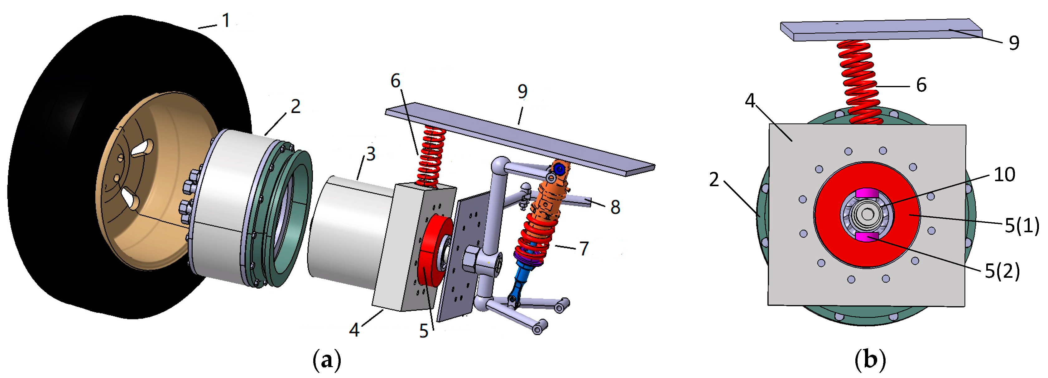
As shown in Figure 1, the proposed electric wheel contains the following parts:
- (1)
- In-wheel motor (IWM). As shown in Figure 1a, the IWM is a permanent magnet synchronous motor with an outer rotor. The two ends of the rotor are bolted to the wheel hub and brake disc, respectively, to move and stop the wheel. One end of the hollow motor stator is extended with a square block to which the in-wheel spring and damper are installed.
- (2)
- In-wheel vibration absorber. Figure 1b is a front view of the proposed in-wheel vibration absorber. The absorber is composed of a spring and a damper. The spring is mounted to an outer edge of the motor extension and another end of the spring is connected to vehicle body. The spring can passively absorb motor and body vibrations. Besides, the damper consists an annular rubber bushing and a controllable damper. The controllable damper is installed into the annular rubber bushing which is sheathed outside wheel shaft. The annular rubber bushing is utilized to absorb vibration passively, and the controllable damper force can be controlled according to the driving conditions to actively suppress the vertical vibrations of the motor.
2.2. Dynamics Modeling of 1/4 Vehicle
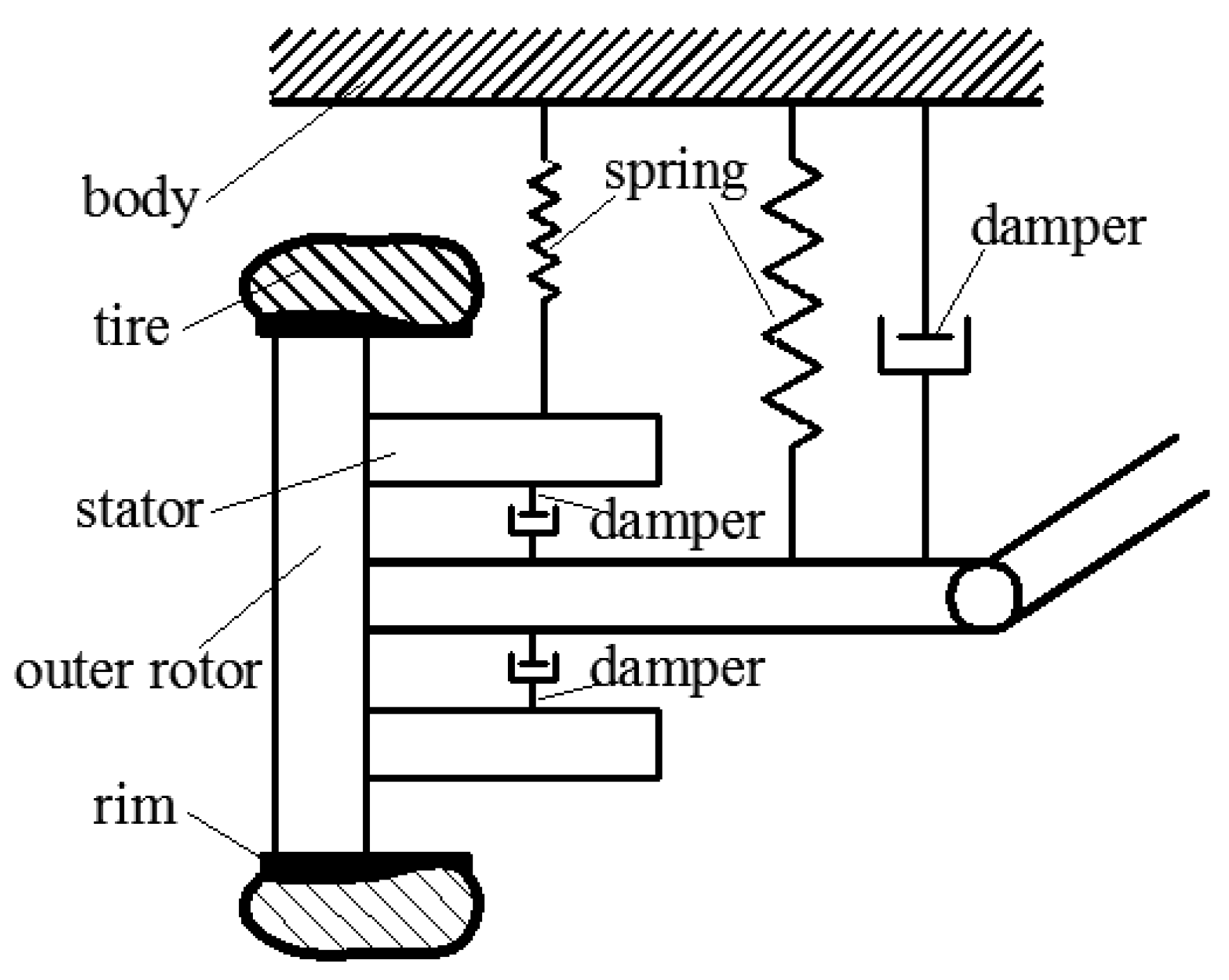
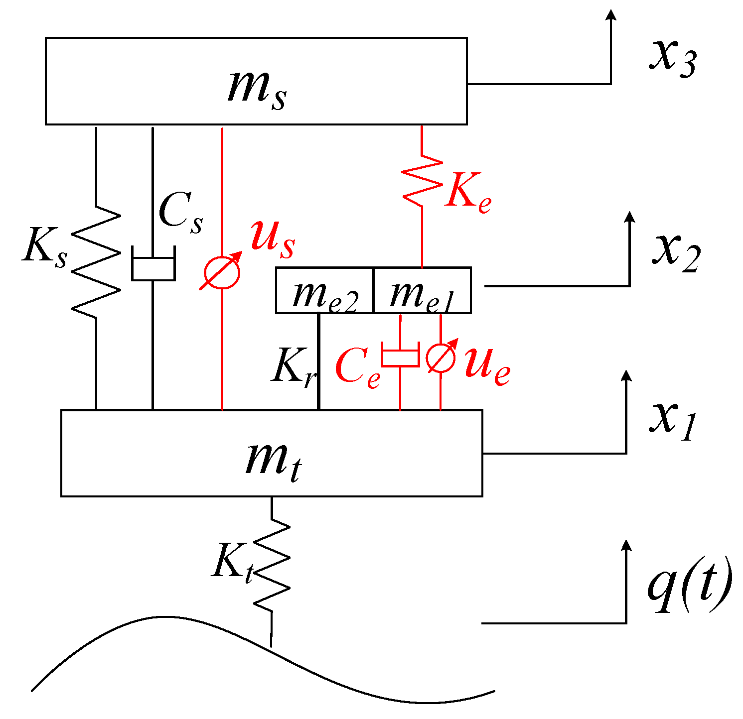
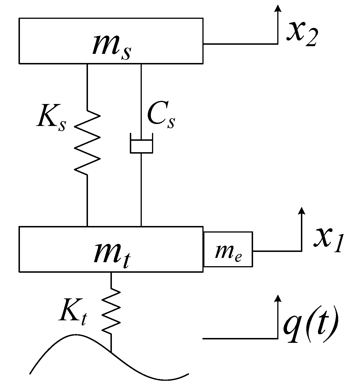
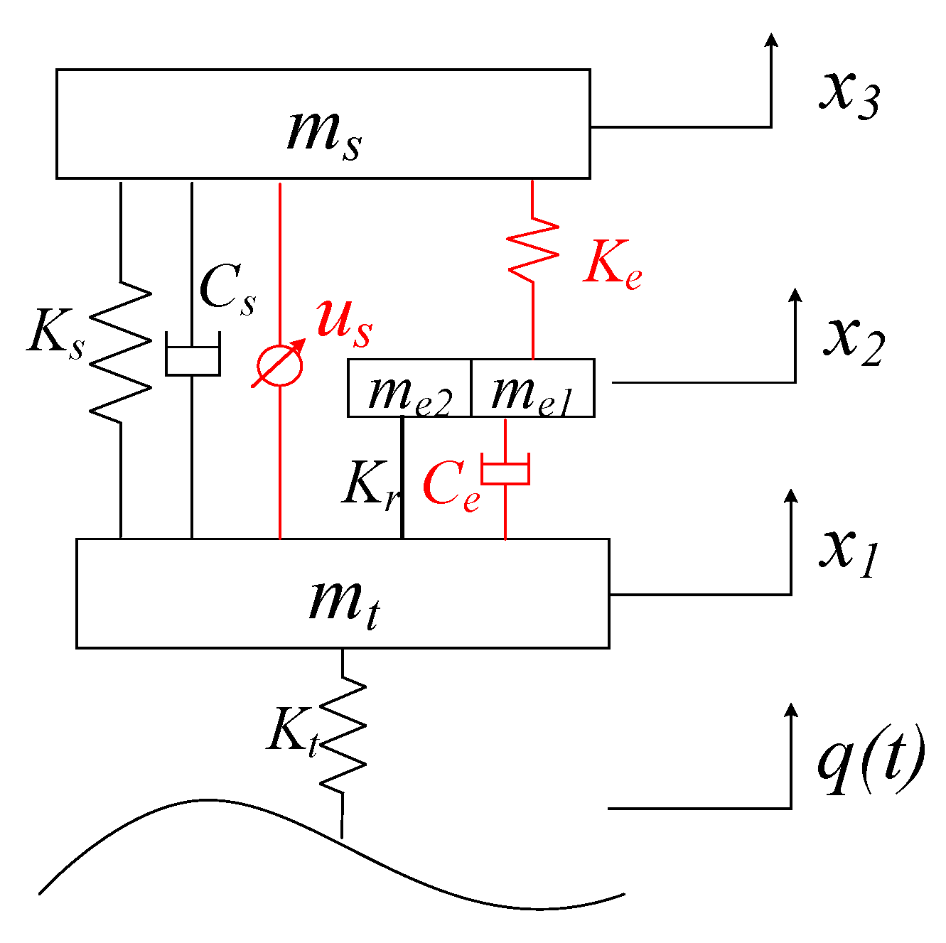
A simplified functional structure of a quarter vehicle with the proposed electric wheel is illustrated in Figure 2. There are two vibration system in the quarter vehicle, the in-wheel vibration absorber and the vehicle suspension. Considering the stator and motor as an integrated part and ignoring their relative vertical movement, the dynamics model of quarter vehicle can be developed as shown in Figure 3, where ms, mt, me1, me2 represent the quarter body mass, wheel assembly mass (including tire, rim, axle, etc.), motor stator mass, motor rotor mass (including rotor and brake disc), respectively. Accordingly, Ks, Kt, Ke, Kr represent the suspension stiffness, tire vertical stiffness, in-wheel spring stiffness, bolt stiffness, respectively. Cs and Ce represent the controllable damping coefficients of the vehicle suspension and in-wheel damper, respectively. Moreover, us and ue represent the controlled force on suspension and in-wheel damper, respectively.
In addition, x1, x2, x3 are vertical displacement of wheel assembly, in-wheel motor and vehicle body, respectively, and q(t) is the pavement input.
From the dynamic model as shown in Figure 3, the differential equations of quarter vehicle can be written as:
There are three degrees of freedom with the quarter vehicle model, the vertical movements of vehicle body, in-wheel motor, and tire. Considering one-mass under the condition of undamped vibration, Equations (1)–(3) can be simplified as:
Based on Equations (4)–(6), the undamped natural frequencies of tire, in-wheel motor, and body can be derived as:
where , and are undamped natural frequency of tire, motor, and body, respectively. Since the bolt stiffness Kr is far greater than Ks, Kt and Ke, and can be considered approximately equal and they are much greater than and usually exceed the range of the normal road excitation frequency. This means that the tire and motor shall vibrate together as a single-mass. Based on this observation, taking the tire and motor as the electric wheel mass, the undamped natural frequencies of the electric wheel and body can be rewritten as:
3. Optimization Control of In-Wheel Vibration Absorber and Vehicle Suspension
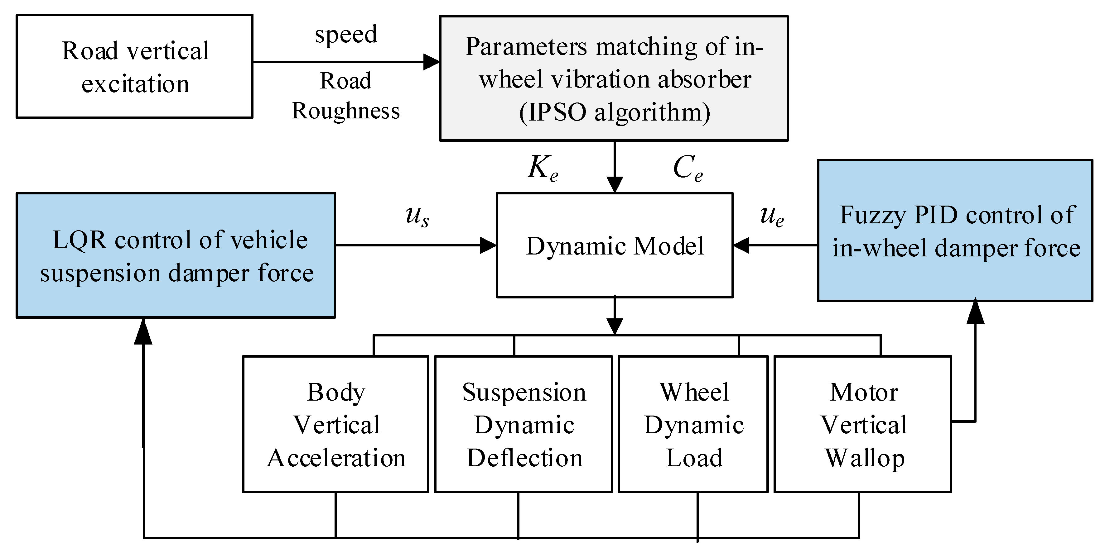
As mentioned in the previous section, the proposed in-wheel vibration absorber and vehicle suspension can be controlled to reduce motor wallop so as to improve the vehicle ride comfort. In this study, four factors are considered as the evaluation indexes to evaluate the control effectiveness, including vehicle body vertical acceleration as, suspension dynamic deflection fd, wheel dynamic load Fd, and motor wallop Fe. As shown in Figure 4, the comprehensive control strategy of the in-wheel absorber and vehicle suspension mainly include the following two aspects:
- (1)
- Parameter matching of the in-wheel vibration absorber. The in-wheel spring and annular rubber bushing are both utilized to absorb vibration passively. Under typical conditions, the improved particle swarm optimization (IPSO) algorithm can be utilized to solve the in-wheel spring stiffness Ke and the damper coefficient of the annular rubber bushing Ce.
- (2)
- Comprehensive control of the vehicle suspension force and the in-wheel damper force. In order to restrain the vertical vibration of vehicle body and the IWM, the body acceleration as and the motor wallop Fe can be chosen as the primary optimization variables, and the suspension dynamic deflection fd and the wheel dynamic load Fd as auxiliary optimization variables. In this study, the linear quadratic regulator algorithm (LQR) algorithm is suggested to control vehicle suspension force us to suppress vehicle body vibration, and meanwhile the fuzzy PID controller is suggested to adjust the in-wheel damper force ue to reduce motor wallop.
The vehicle ride comfort improvement is achieved by the suspension controlled force us and the in-wheel controlled damper force ue. It should be mentioned that the realization of the controlled force differs in different types of actuators, such as magnetorheology (MR), electrorheology (ER), electromagnetic actuator, linear electric motor actuator and so on. In addition, the nonlinear disturbance and uncertainties of actuators are in practice various too. Therefore, in this study, we mainly focus on the damper force control for vibration absorbing, and it is assumed that the controllable damper can deliver a controlled force to meet the vehicle performance requirements as expected.
3.1. Parameters Matching of the In-Wheel Spring and Rubber Bushing
Based on the transfer function, the Fourier transform method is usually adopted to achieve parameter matching [32]. Since it is difficult to derive the transfer function for a system with multiple degrees-of-freedom, some scholars have suggested using the genetic algorithm to match the vehicle suspension parameters [22]. As a matter of fact, it is complicated to program the genetic algorithm with memory function characteristics, which weakens its effectiveness.
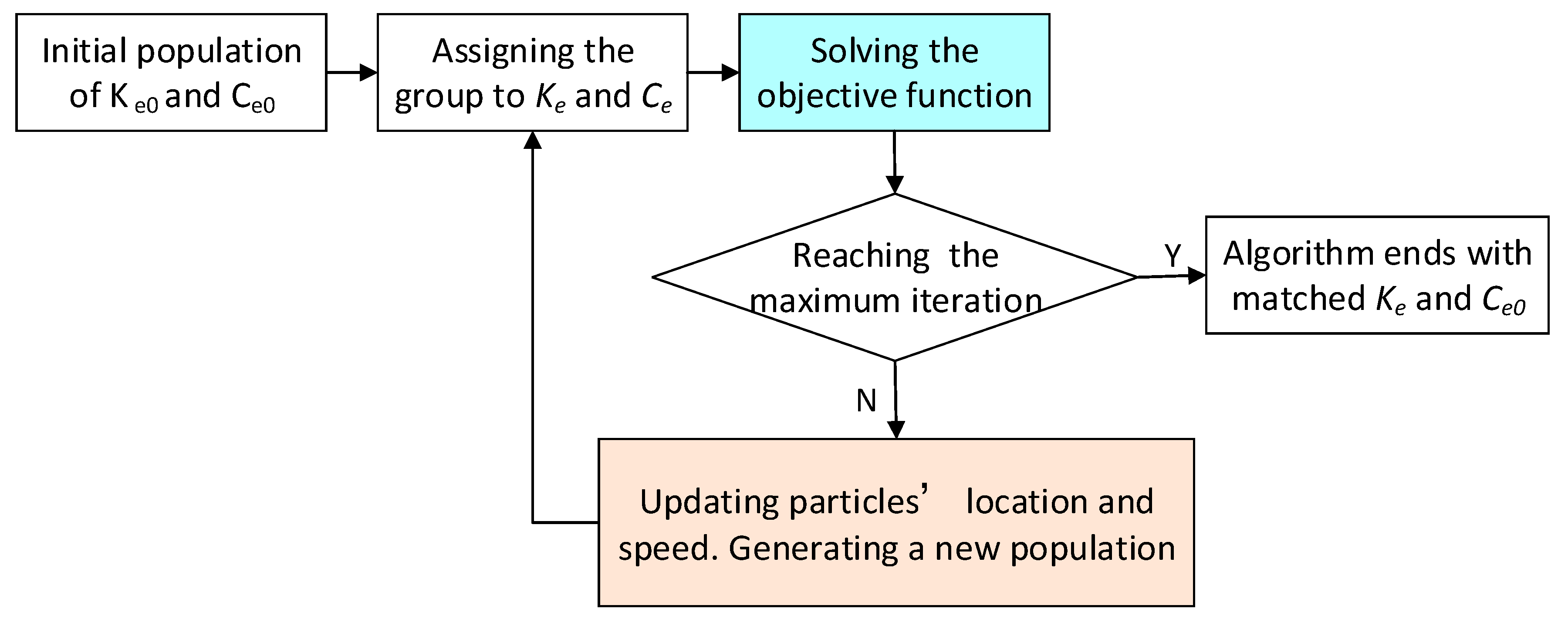
As shown in Figure 5, the improved particle swarm optimization (IPSO) algorithm, based on the social behavior of individuals and groups, which features simple programming and easy implementation [33], is utilized to determine the in-wheel absorber’s parameters. When parameters are matched by IPSO, each particle represents a set of two-dimension constants, in-wheel spring stiffness and damper coefficient. The particles can dynamically update the optimization speed to achieve the optimal trajectory.
3.1.1. Updating Particles’ Lacation and Speed
Considering the parameter matching of the in-wheel spring and rubber bushing as a two-dimensional optimization problem, the updating functions of the particles’ optimization speed and positions can be written as:
In Equations (9) and (10), i is the particle number, j the optimal dimension number, and t the iterations number. vij(t) and xij(t) represent the optimization speed and position at the tth iteration, respectively. pbestij(t) and gbestij(t) are the partial optimal position and the global optimal position, respectively. W is the inertia weight factor. c1 and c2 are the cognitive learning factor and the social learning factor, respectively. r1 and r2 are the random numbers [0,1], respectively.
The inertia weight factor is an important index which greatly affects the optimization effect. When a large inertia weight factor is selected, the global optimization ability of IPSO becomes strong, but the convergence ability gets worse. On the contrary, when a small inertia weight factor is selected, the global search ability becomes weak, but the local search ability becomes strong and the search results can quickly converge. Therefore, it is necessary to dynamically adjust the inertia weight factor to improve the flexibility of the IPSO. In the early stage of the algorithm, a large inertial weight factor is set to enhance the global search ability, while in the later stage, a relatively small value is set to enhance the local search ability of the particle near the optimal solution, while, the convergence is accelerated.
At present, adjustment of the inertia weight factor is realized through linear or nonlinear decreasing methods. The linear method features easy control and intuitive effectiveness, but its parameter matching is often not optimized. In this study, the nonlinear decreasing method is employed to adjust the inertia weight factor. The adjustment scheme for the inertia weight is based on a decreasing function as below:
where t is the current iteration number, and tmax is the maximum number of iterations. W1 is the inertia weight factor in the early stage, while W2 in the later stage. W1 and W2 are set to 0.9 and 0.4, respectively, i.e., W(1) is 0.9 and W(tmax) = 0.4. The constant of 0.875 is to ensure that W varies in the range of [0.4,0.9].
3.1.2. Solving Objective Funtio
As the evaluation indexes, the four factors, vehicle body vertical acceleration as, suspension dynamic deflection fd, wheel dynamic load Fd, and motor wallop Fe, can be expressed as:
In order to compare the performance of the proposed electric wheel with that of the conventional electric wheel, taking the in-wheel stiffness Ke and damping coefficient Ce as optimization variables, the objective function is established as:
where as(σ), fd(σ), Fd(σ) and Fe(σ) represent the RMS values of as, fd, Fd and Fe of IWMs EV with the proposed electric wheel, respectively. as(ω), fd(ω), Fd(ω) and Fe(ω) are the RMS values of the four indexes of the IWMs EV with conventional electric wheel, respectively. α, β, λ and η are the weight coefficients of the four indexes, respectively.
According to the requirements of “primarily optimizing the body vertical acceleration and the motor wallop, and secondarily optimizing the suspension dynamic deflection and the wheel dynamic load”, both α and η are set to 2, and both β and λ are set to 1.
In order to ensure the wheel-road adhesion and vehicle driving stability, the probability of the wheel moving off the road should be less than 0.15%, and the probability of the suspension impacting the limit block should be less than 0.3%. The constraint condition is as follows:
where G is the static load on the wheel and G = (ms + mt + me1 + me2)g. [fd] is the allowable value of the suspension dynamic deflection, and it is set to 80 mm.
In this study, the motor rotor and the rim are connected together through bolts. For better motor performance, the vertical displacement between the hub and motor should be less than 6 mm, and its RMS value is less than 2.5 mm, as shown below:
The basic parameters of the IPSO algorithm are set as follows. The population size is set to 30. The inertia weight factor is based on the nonlinear decreasing adjustment method, where the initial and final values are set to 0.9 and 0.4, respectively. The maximum number of iterations is set to 200. The acceleration factors c1 and c2 are set to 2. The reference range of parameter Ke is set to [0,30,000] N/m and the reference range of Ce is set to [0,8000] N·s/m.
Under the typical conditions of the C-class pavement at a speed of 70 km/h, the optimized parameters of in-wheel spring Ke and damper Ce are as follows:
3.2. LQR Control of the Vehicle Suspension Damper Force
The proposed in-wheel vibration absorber is to reduce motor wallop. Meanwhile, it also changes the dynamics characteristics of vehicle, leading to ineffectiveness of the original suspension. Therefore, it is necessary to control vehicle suspension according vehicle operation conditions. In this study, the vehicle suspension damper force is controlled to improve vehicle ride comfort by utilizing the linear quadratic regulator (LQR) algorithm. From Equations (1)–(3), the quarter vehicle model can be rewritten as the linear state equation as:
where x is variable states matrix, y outputs matrix, and u the controlled force of suspension damper. A, B, C, D and G are coefficient matrixes. w is road excitation . They are expressed as:
The objective function is established based on the four evaluation indexes, vehicle body vertical acceleration, suspension dynamic deflection, wheel dynamic load and motor vertical acceleration, as shown below:
where q1, q2, q3, q4 are the weighed coefficients of vehicle body vertical acceleration, suspension dynamic deflection, wheel dynamic load, and motor vertical acceleration, respectively.
Based on the Equation (17), the objective function in Equation (18) can be deuced as:
where Q is the weighted coefficient matrix of the state variables and R is the weighted coefficient matrix of the input variables. Both Q and R are positive definite matrices. N is the associated matrix of Q and R. They can be deduced as:
According to the optimal control theory, we can solve the suspension controllable force us, as the optimal solution of objective function (Equation (19)):
where K is feedback gain matrix, which can be solved by the Riccati equation as:
With MATLAB software, the feedback gain matrix K can be solved by using the LQR function as:
As shown in the objective function Equation (18), the weighed coefficients q1, q2, q3, q4 enormously influence the optimization effectiveness. In this study, q1, q2, q3, q4 are obtained by using the IPSO introduced above as:
3.3. Fuzzy PID Control of In-Wheel Damper Force
The in-wheel vibration absorber with the matched parameters determined in the previous section can function effectively to reduce motor wallop under most vehicle operation conditions. However, due to the complexity of the road excitation, the in-wheel absorber with fixed parameters cannot exploit this to achieve an optimum performance. Additionally, since the in-wheel absorber is intercoupled with the vehicle suspension, it is essential to control the in-wheel absorber to further improve vehicle ride comfort.
In this section, a fuzzy PID controller is designed to adjust the in-wheel controllable damper force. A two-dimension fuzzy controller is employed to determine the coefficients of the PID controller, Kp, Ki, and Kd. The motor vertical acceleration Eae and its gradient ECae are taken as inputs for the fuzzy controller. The main parameters of the fuzzy controller are determined as follows:
- The basic domains of Eae and ECae are set to [−6,6] and [−60,60], respectively, and the relevant fuzzy domains are both set to [−6,6]. The quantization factors are set as ke = 1 and kec = 0.1.
- The basic domains of output Kp, Ki and Kd are set to [−60,60], [−0.6,0.6], and [−0.00006,0.00006], respectively. The relevant fuzzy domains are all set to [−6,6]. The scale factors are set as kp = 10, ki = 0.1, kd = 0.00001. The initial values of Kp, Ki and Kd are set as:
- Seven fuzzy languages are selected to describe the values of inputs and outputs. They are Positive-Big (PB), Positive-Medium (PM), Positive-Small (PS), Zero (Z), Negative-Small (NS), Negative-Medium (NM), and Negative-Big (NB).
- All fuzzy subsets’ membership functions are selected as triangular functions.
Based on comprehensive simulations, fuzzy rules for Kp, Ki and Kd are established, as shown in Table 1, Table 2 and Table 3, respectively. The relevant fuzzy surface of Kp, Ki and Kd are shown in Figure 6a–c.
In order to suppress the motor vibration, motor vertical acceleration ae is taken as the input of PID controller. The controlled damper coefficient and force can be expressed as:
4. Simulations and Discussions
In order to verify the performance of the proposed in-wheel vibration absorber and control algorithms, simulations under the typical conditions, including the random pavement and pulse pavement, were carried out with MATLAB/Simulink software. The following IWM EVs with different electric wheel schemes are applied in the simulations:
- (1)
- The conventional electric wheel scheme without an in-wheel absorber, used in the passive suspension of vehicle (marked as NWR-PS), as shown in Figure 7.
- (2)
- (3)
- The electric wheel scheme with an in-wheel passive absorber, featured with in the controllable suspension force based on LQR method (marked as WPR-SS), as shown in Figure 9.
- (4)
- The electric wheel scheme with an in-wheel controllable absorber and the controllable suspension force proposed in this paper (marked as WSR-SS (1)), as shown in Figure 3.
- (5)
- The electric wheel scheme of WSR-SS as shown in Figure 3, whereas, the suspension force is controlled based on fuzzy rules as in-wheel damper force, rather than based on the LQR method. It is marked as WSR-SS (2).
The basic parameters of the above IWM EVs are as listed in Table 4:
4.1. Simulation under Pavement Random Excitation
The simulation was carried out at the C-class pavement with the speed of 70 km/h. The power spectral density (PSD) curves of vehicle body vertical acceleration, motor vertical wallop, wheel dynamic load, and suspension dynamic deflection are illustrated in Figure 10, Figure 11, Figure 12 and Figure 13.
It is worth to note that, as expressed above, the tire and IWM are considered as an integrated electric wheel mass in the spectral analysis. Based on Equation (8) and the vehicle parameters in Table 4, in the IWM EVs with in-wheel absorbers, including WPR-PS, WPR-SS and WSR-SS, the numerical results of natural frequencies of electric wheel w1w and vehicle body w1s are:
In the IWM EVs without in-wheel absorbers, including NWR-PS, the numerical results of natural frequencies of electric wheel w2w and vehicle body w2s are:
This indicates that the relatively small value of in-wheel spring stiffness Ke shall result in larger natural frequencies of wheel and body for the IWM EV with an in-wheel absorber than those for the IWM EV without an in-wheel absorber, which can be also observed from the following frequency characteristics.
Figure 10 shows the PSD curves of vehicle body vertical acceleration. It can be seen that at the natural frequency of the electric wheel (about 8.8 Hz), compared with NWR-PS, the other four electric wheels have much smaller vehicle body vertical acceleration, which indicates that the in-wheel absorption greatly contributes to suppression of the body vibration at the natural frequency of the wheel. In addition, at the natural frequency of the vehicle body (about 1.3 Hz), the body vertical acceleration of WPR-PS is larger than that of NWR-PS, which means that the in-wheel absorber deteriorates the suspension performance to a certain degree. It should be pointed out that body vertical acceleration of WPR-SS and WSR-SS are much smaller than those of the others. This means that the suspension control overcomes the negative effect of in-wheel absorber and improves vehicle ride comfort as well. In addition, at the natural frequency of the vehicle body (about 1.3 Hz), the body vertical acceleration of WSR-SS (1) is smaller than that of WSR-SS (2), which means that the LRQ method is better than the fuzzy control method in the suspension control.
Figure 11 shows the PSD curves of the motor vertical wallop. It can be seen that, at the natural frequency of the electric wheel (about 8.8 Hz), the motor vertical wallop of NWR-PS is apparently larger than that of the other four schemes, which indicates that the in-wheel absorber effectively reduces the motor vertical wallop. In particular WSR-SS (1) has the smallest motor vertical wallop, which means that the in-wheel damper control further dampens the wheel vibration, and in which the LQR method exhibits superior performance in comparison to the fuzzy control.
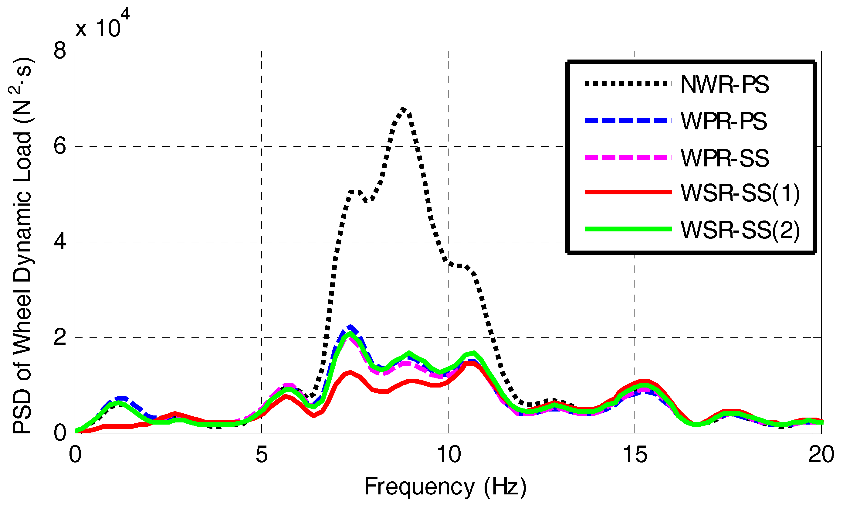
Figure 12 shows the PSD curves of the wheel dynamic load. It can be seen that the wheel dynamic load follows a similar variation pattern as the motor wallop, and the WSR-SS (1) has the best performance. This is duo to the mechanical restrains between wheel and motor, which makes motor vibrate in sync with the wheel.
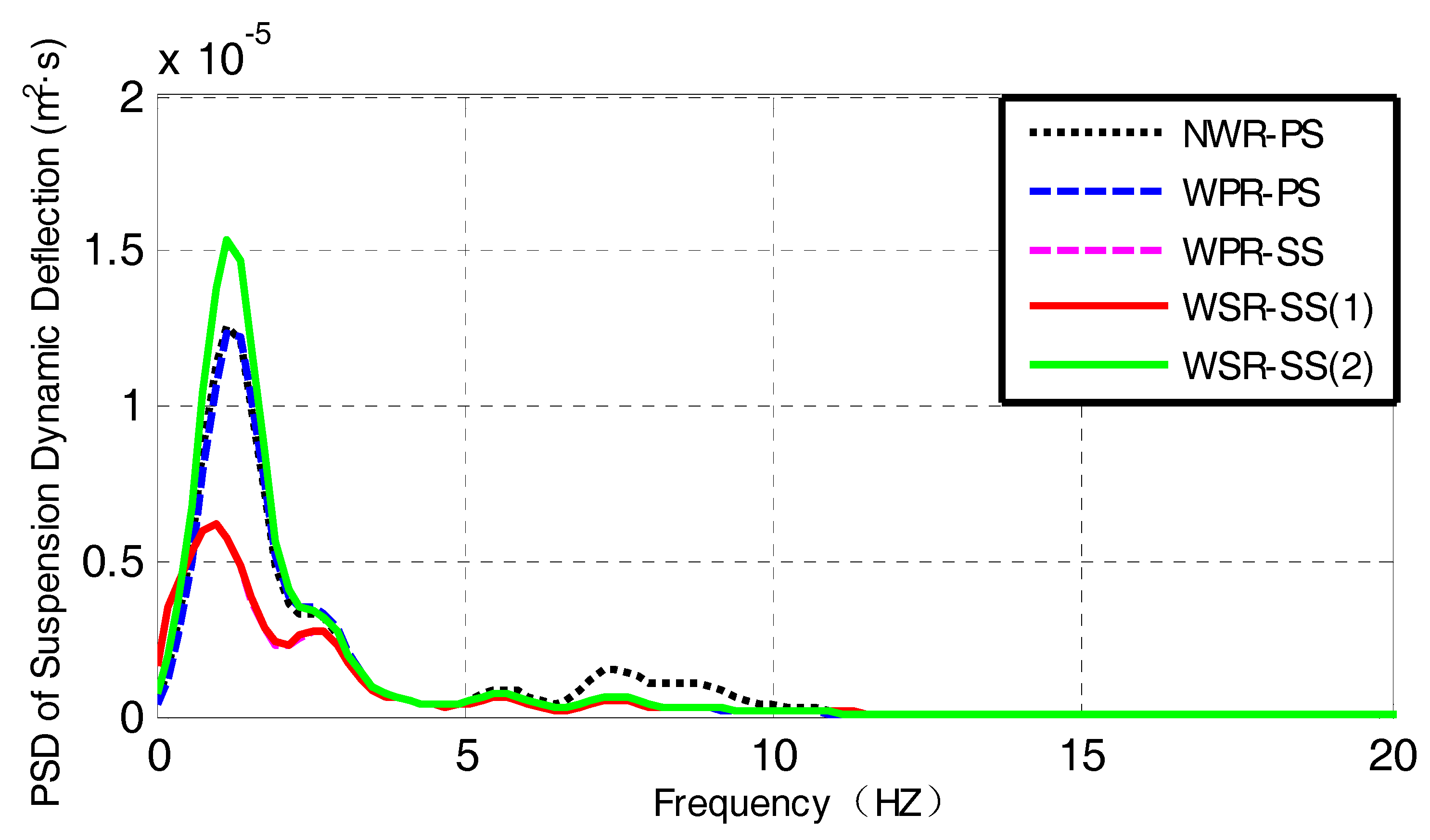
Figure 13 shows the PSD curves of suspension dynamic deflection. It can be seen that, at the natural frequency of the vehicle body (about 1.3 Hz), suspension dynamic deflections of WPR-SS and WSR-SS (1) are much smaller than those of the other three schemes, which indicates that the suspension damper force control based on the LQR method improves vehicle ride comfort.
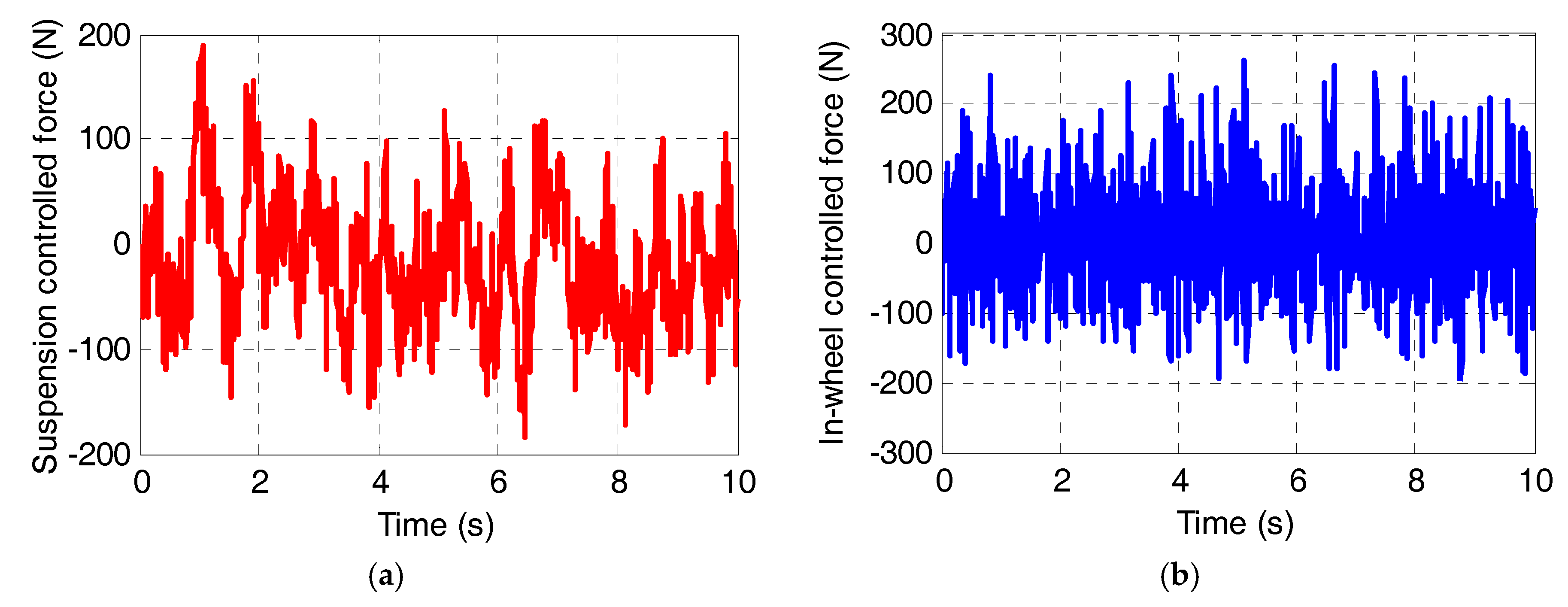
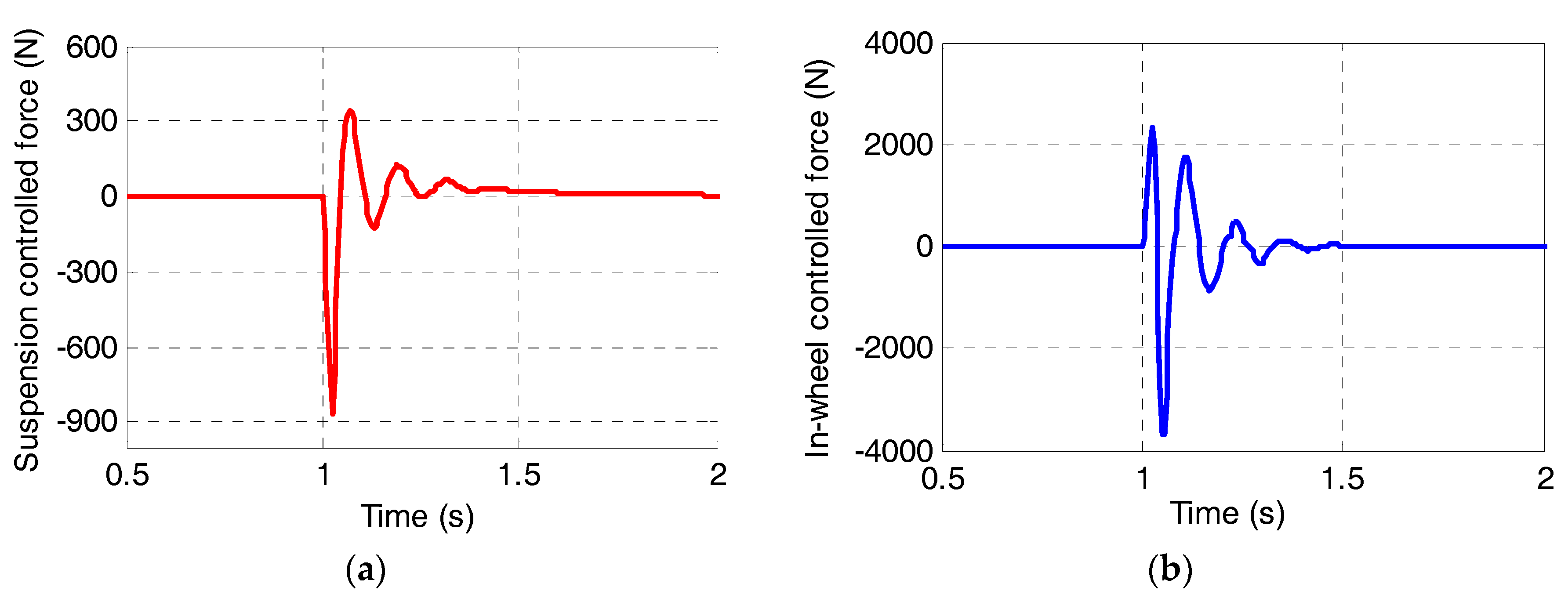
Figure 14 shows the controlled force for vehicle suspension and in-wheel absorber in the WSR-SS (1) scheme. As shown in Figure 14a, the suspension controlled force us determined by the LQR method varies in the range of −200 N to 200 N. As shown in Figure 14b, the in-wheel controlled force ue determined by the fuzzy PID controller varies in the range of −200 N to 300 N.
4.2. Simulation under Pavement Pulse Excitation
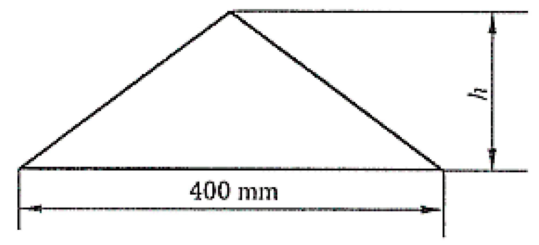
In this simulation, a pavement pulse excitation is applied to electric wheels. As shown in Figure 15, a speed bump is shaped as a triangular bump with height of 40 mm and base of 400 mm.
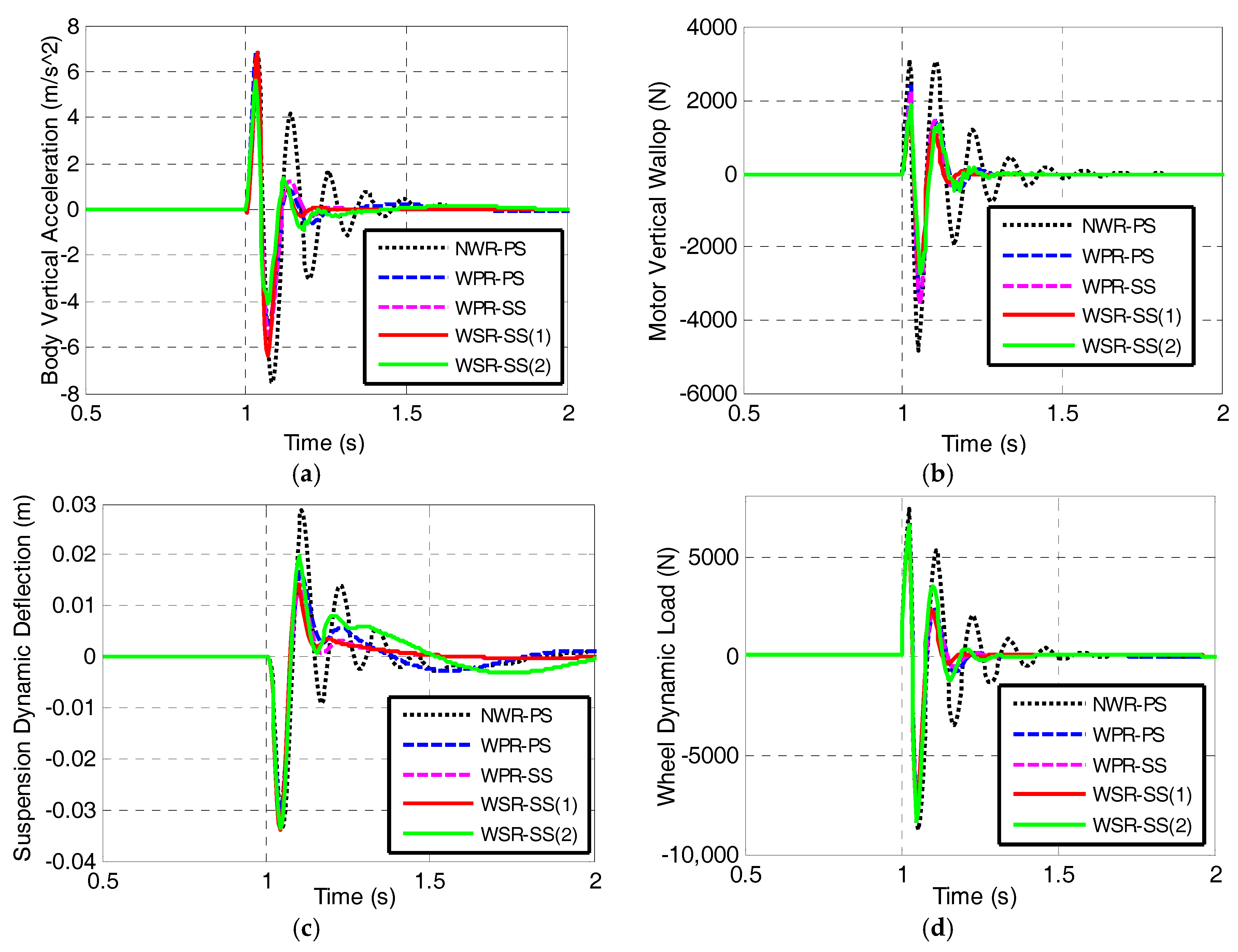
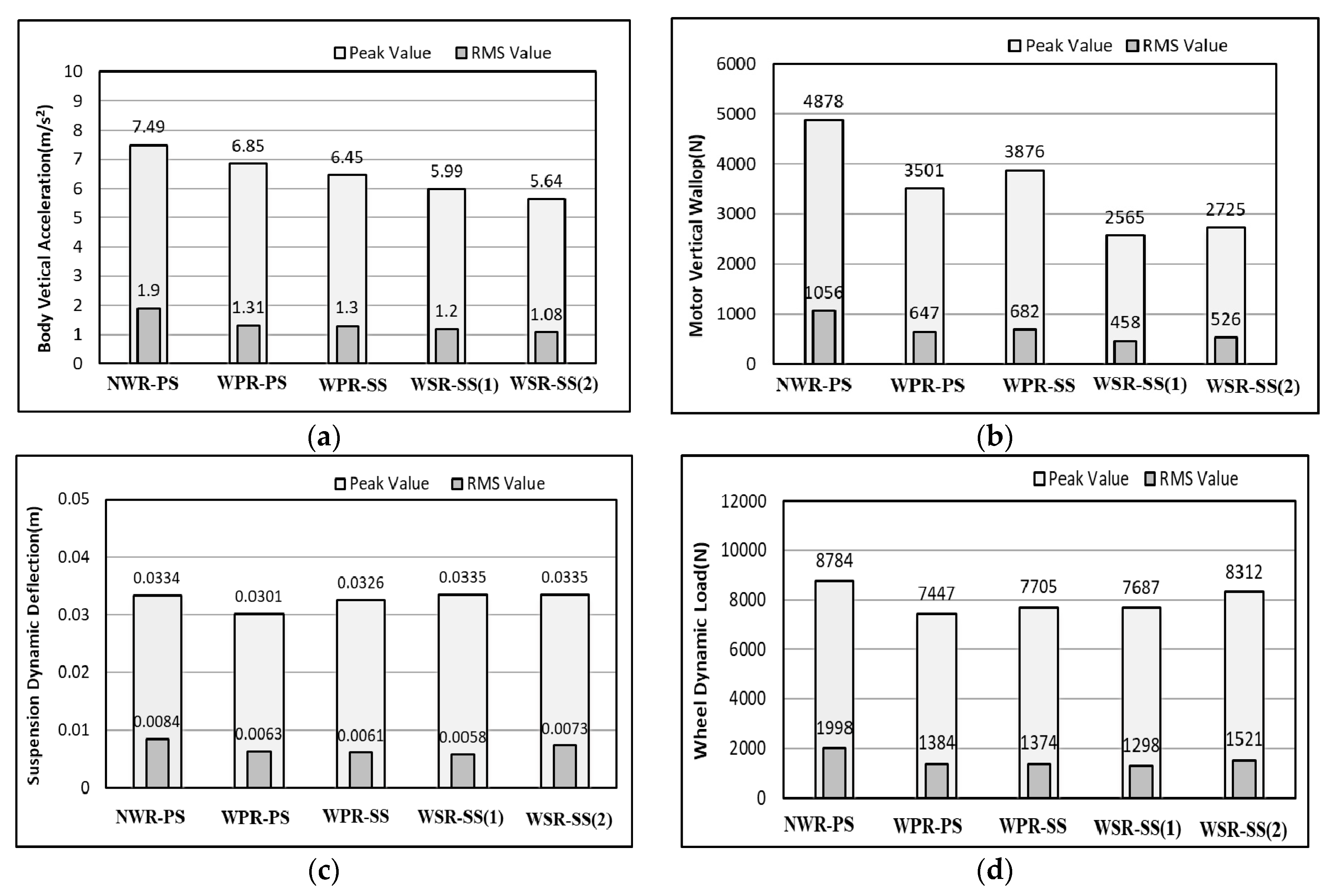
Vehicles cross the speed bump at the speed of 30 km/h. The time-domain response curves of vehicle body vertical acceleration, motor vertical wallop, suspension dynamic deflection, and wheel dynamic load are shown in Figure 16a–d.
As shown in Figure 16, compared with the NWR-PS, the four evaluation indexes of the other four electric wheels are smaller, and the periods of their transients are much shorter. This observation suggests that the comprehensive control of in-wheel absorber and vehicle suspension is effective. Based on Figure 16, the statistical peak values and RMS values of the four evaluation indexes are shown in Figure 17a–d.
As shown in Figure 17a, compared with the NWR-PS, the peak value and RMS value of the body vertical acceleration in the WPR-PS scheme are optimized by 9% and 31%, respectively. The values with the WPR-SS are further decreased by 6%, which verifies the effectiveness of the suspension control. Besides, the peak value and RMS value of the body vertical acceleration in the WSR-SS (2) scheme are smaller than those in the WSR-SS (1) scheme, which indicates that the fuzzy control performs better than the LQR method in the body vibration suppression under this condition.
As shown in Figure 17b, compared with the NWR-PS, the peak value and the RMS value of the motor vertical wallop of the WSR-SS are reduced by 41.4% and 52.1%, respectively, which indicates that the in-wheel absorber greatly suppresses the wheel vibration. Especially, the WSR-SS (1) scheme has the smallest values of the motor vertical wallop. It means that the LQR method exhibits best performance in the motor vibration suppression. Figure 17c,d show that the WSR-SS (1) has the best performance in suspension dynamic deflection and wheel dynamic load as well. The controlled force for the vehicle suspension and the in-wheel absorber in the WSR-SS (1) scheme is shown in Figure 18.
5. Conclusions
This paper presents an in-wheel vibration absorber for IWMEV and a comprehensive control strategy for an in-wheel absorber and vehicle suspension to improve vehicle ride comfort. The key conclusions include:
- (1)
- The proposed in-wheel vibration absorber consists of a spring, an annular rubber bushing, and a controllable damper. The spring and the rubber bushing to restrain the wheel vibration passively, and the controllable damper is controlled to further restrain the wheel and motor vibration adaptively.
- (2)
- Under typical driving conditions, the IPSO algorithm is utilized to determine the parameters of the in-wheel spring and rubber bushing. The in-wheel absorber with the matched parameters can effectively restrain the motor vibration under most conditions.
- (3)
- There are negative interaction effects between vehicle suspension and in-wheel absorber, which can be overcame by using LQR control of suspension force and fuzzy PID control of in-wheel damper force. The performance of the proposed control strategy has been examined through simulations under random pavement excitation and pavement pulse excitation conditions. The results show that the proposed LQR controller effectively improves vehicle ride comfort and the fuzzy PID controller further suppresses motor vibration and reduces motor vertical wallop as well.
Acknowledgments
The project is supported by the National Nature Science Foundation of China (No. 51605214), the Nature Science Foundation of Jiangxi Province (No. 20171BAB216028) and the Open Research Subject of Key Laboratory of Automobile Engineering of Sichuan Province (No. sjzz2016-082). Thanks Changjiang Wang for checking the English language.
Author Contributions
Mingchun Liu built the electric wheel structure and the 1/4 IWM EVs dynamics model. Yuanzhi zhang developed the control strategy. Feihong Gu helped with the simulation. All authors carried out the data analysis, discussed the results and contributed to writing the paper.
Conflicts of Interest
The authors declare no conflict of interest.
References
- Yu, Z.; Feng, Y.; Xiong, L. Review on Vehicle Dynamics Control of Distributed Drive Electric Vehicle. J. Mech. Eng. 2013, 49, 105–114. [Google Scholar] [CrossRef]
- Yoshimura, M.; Fujimoto, H. Driving Torque Control Method for Electric Vehicle with In-Wheel Motors. IEEJ Trans. Ind. Appl. 2011, 131, 721–728. [Google Scholar] [CrossRef]
- Wang, Z.; Wang, Y.; Zhang, L.; Liu, M. Vehicle Stability Enhancement through Hierarchical Control for a Four-Wheel-Independently-Actuated Electric Vehicle. Energies 2017, 10, 947. [Google Scholar] [CrossRef]
- Watts, A.; Vallance, A.; Whitehead, A.; Hilton, C. The technology and economics of in-wheel motors. SAE Int. J. Passeng. Cars 2010, 3, 37–54. [Google Scholar] [CrossRef]
- Zhang, X.; Liang, Y.; YU, E.; Rao, R.; Xie, J. Review of electric vehicle policies in China: Content summary and effect analysis. Renew. Sustain. Energy Rev. 2016, 70, 698–714. [Google Scholar] [CrossRef]
- Wang, R.; Chen, Y.; Feng, D.; Huang, X.; Wang, J. Development and performance characterization of an electric ground vehicle with independently actuated in-wheel motors. J. Power Sources 2011, 196, 3962–3971. [Google Scholar] [CrossRef]
- Chen, X.; Yin, J.; Wang, W.; Wu, L.; Tang, F. Approaches to diminish large unsprung mass negative effects of wheel side drive electric vehicles. J. Adv. Mech. Des. Syst. Manuf. 2016, 10, 1–2. [Google Scholar] [CrossRef]
- Wang, R.; Jing, H.; Yan, F.; Karimi, H.; Chen, N. Optimization and finite-frequency H∞ control of active suspensions in in-wheel motor driven electric ground vehicles. J. Franklin Inst. 2015, 352, 468–484. [Google Scholar] [CrossRef]
- Tan, D.; Lu, C. The Influence of the Magnetic Force Generated by the In-Wheel Motor on the Vertical and Lateral Coupling Dynamics of Electric Vehicles. IEEE Trans. Veh. Technol. 2016, 65, 4655–4668. [Google Scholar] [CrossRef]
- Wang, Y.; Li, Y.; Sun, W.; Zheng, L. Effect of the Unbalanced Vertical Force of a Switched Reluctance motor on the Stability and the Comfort of an In-Wheel Motor Electric Vehicle. Proc. Inst. Mech. Eng. Part D J. Automob. Eng. 2015, 229, 1569–1584. [Google Scholar] [CrossRef]
- Wang, Y.; Li, P.; Ren, G. Electric vehicles with in-wheel switched reluctance motors-Coupling effects between road excitation and the unbalanced radial force. J. Sound Vib. 2016, 372, 69–81. [Google Scholar] [CrossRef]
- Luo, Y.; Tan, D. A Research on the Hub-motor Driven Wheel Structure with a Novel Built-in Mounting System. Automot. Eng. 2013, 35, 1105–1110. [Google Scholar]
- Kacem, M.; Tounsi, S.; Neji, R. Determination of axial flux motor electrical parameters for electric vehicle. In Proceedings of the 2015 6th International Renewable Energy Congress, Sousse, Tunisia, 24–26 March 2015. [Google Scholar]
- Mahmoudi, A.; Rahim, N.; Ping, H. Axial-Flux Permanent-Magnet Motor Design For Electric Vehicle Direct Drive Using Sizing Equation And Finite Element Analysis. Prog. Electromagn. Res. 2012, 122, 467–496. [Google Scholar] [CrossRef]
- Nikam, S.; Vandana, R.; Fernandes, B. A High-Torque-Density Permanent-Magnet Free Motor for In-Wheel Electric Vehicle Application. IEEE Trans. Ind. Appl. 2012, 48, 2287–2295. [Google Scholar] [CrossRef]
- Takahashi, T.; Takemoto, M.; Ogasawara, S.; Hino, W.; Takezaki, K. Size and Weight Reduction of an In-wheel Axial-gap Motor Using Ferrite Permanent Magnets for Electric City Commuters. In Proceedings of the 18th International Conference on Electrical Machines and Systems, Pattaya, Thailand, 25–28 October 2015. [Google Scholar]
- Nagaya, G.; Wakao, Y.; Abe, A. Development of an in-wheel drive with advanced dynamic-damper mechanism. JSAE Rev. 2003, 4, 477–481. [Google Scholar] [CrossRef]
- Shao, X.; Naghdy, F.; Du, H. Reliable fuzzy H∞ control for active suspension of in-wheel motor driven electric vehicles with dynamic damping. Mech. Syst. Signal Process. 2017, 87, 365–383. [Google Scholar] [CrossRef]
- Luo, Y.; Tan, D. Study on the Dynamics of the In-Wheel Motor System. IEEE Trans. Veh. Technol. 2012, 61, 3510–3518. [Google Scholar]
- Oliveira, K.; Cesar, M.; Goncalves, J. Fuzzy based Control of a Vehicle Suspension System using a MR Damper. In Proceedings of the 12th Portuguese Conference on Automatic Control, Guimaraes, Portugal, 14–16 September 2017. [Google Scholar]
- Ma, Y.; Deng, Z.; Xie, D. Analysis and optimization of in-wheel motor suspension configuration. J. Cent. South Univ. 2014, 45, 3008–3013. [Google Scholar]
- Jin, L.; Yu, Y.; Fu, Y. Study on the ride comfort of vehicles driven by in-wheel motors. Adv. Mech. Eng. 2016, 8, 1–9. [Google Scholar] [CrossRef]
- Shen, D.; Ling, X.; Liu, J.; Wang, H. Modelling and Simulation of a Fuzzy PID Controller for Active Suspension System. In Proceedings of the 7th International Conference on Fuzzy Systems and Knowledge Discovery, Yantai, China, 10–12 August 2010. [Google Scholar]
- Kumar, V.; Rana, K.; Kumar, J.; Mishra, P. Self-tuned robust fractional order fuzzy PD controller for uncertain and nonlinear active suspension system. Neural Comput. Appl. 2017, 1–17. [Google Scholar] [CrossRef]
- Zhang, H.; Wang, J. Active steering Actuator Fault Detection for an automatically-steered electric ground vehicle. IEEE Trans. Veh. Technol. 2017, 66, 3685–3702. [Google Scholar] [CrossRef]
- Wang, R.; Zhang, H.; Wang, J. Linear parameter-varying controller design for four-wheel independently actuated electric ground vehicles with active steering systems. IEEE Trans. Control Syst. Technol. 2014, 22, 1281–1296. [Google Scholar]
- Badri, P.; Amini, A.; Sojoodi, M. Robust fixed-order dynamic output feedback controller design for nonlinear uncertain suspension system. Mech. Syst. Signal Process. 2016, 80, 137–151. [Google Scholar] [CrossRef]
- Du, H.; Zhang, N. Fuzzy control for nonlinear uncertain electrohydraulic active suspensions with input constraint. IEEE Trans. Fuzzy Syst. 2009, 17, 343–356. [Google Scholar]
- Guo, D.; Hu, H.; Yi, J. Neural network control for a semi-active vehicle suspension with a magnetorheological damper. J. Vib. Control 2004, 10, 461–471. [Google Scholar] [CrossRef]
- Wang, R.; Song, Y.; Xue, Y.; Jing, H.; Hou, J.; Zhao, M. An optimal vibration control strategy for a vehicle’s active suspension based on improved cultural algorithm. Appl. Soft Comput. 2015, 28, 167–174. [Google Scholar] [CrossRef]
- Sun, W.; Gao, H.; Yao, B. Adaptive robust vibration control of full-car active suspension with electrohydraulic actuators. IEEE Trans. Control Syst. Technol. 2013, 21, 2417–2422. [Google Scholar] [CrossRef]
- Marinakis, Y.; Migdalas, A.; Sifaleras, A. A hybrid Particle Swarm Optimization-Variable Neighborhood Search algorithm for Constrained Shortest Path problems. Eur. J. Oper. Res. 2017, 261, 819–834. [Google Scholar] [CrossRef]
- Agarwalla, P.; Mukhopadhyay, S. Efficient player selection strategy based diversified particle swarm optimization algorithm for global optimization. Inf. Sci. 2017, 397, 69–90. [Google Scholar] [CrossRef]
- Tan, D.; Lu, C.; Ren, C. Optimal matching between the suspension and the rubber bushing of the in-wheel motor system. Proc. Inst. Mech. Eng. Part D J. Automob. Eng. 2014, 229, 758–769. [Google Scholar] [CrossRef]
Figure 1.
Structure of electric wheel with in-wheel vibration absorber. (a) Electric wheel Structure; (b) In-wheel vibration absorber. 1—Tire; 2—Motor rotor; 3—Motor stator; 4—Stator extension; 5—In-wheel damper; 5(1)—Annular rubber bushing; 5(2)—Controllable damper; 6—In-wheel spring; 7—Vehicle suspension; 8—Steering kunckle; 9—Vehicle body; 10—Wheel shaft.

Figure 2.
Simplified structure of quarter vehicle.

Figure 3.
Dynamics model of quarter vehicle.

Figure 4.
Comprehensive control strategy.

Figure 5.
Initial parameter matching of the in-wheel absorber based on the IPSO algorithm.

Figure 6.
Fuzzy surfaces for Kp, Ki and Kd. (a) Fuzzy surface for Kp; (b) Fuzzy surface for Ki; (c) Fuzzy surface for Kd.
Figure 6.
Fuzzy surfaces for Kp, Ki and Kd. (a) Fuzzy surface for Kp; (b) Fuzzy surface for Ki; (c) Fuzzy surface for Kd.
Figure 7.
NWR-PS scheme.

Figure 8.
WPR-PS scheme.
Figure 9.
WPR-SS scheme.

Figure 10.
The PSD curve of vehicle body vertical acceleration.

Figure 11.
The PSD curve of motor vertical wallop.
Figure 12.
The PSD curve of wheel dynamic load.

Figure 13.
The PSD curve of suspension dynamic deflection.

Figure 14.
Controlled force for vehicle suspension and in-wheel abosrber in the WSR-SS (1) schemes. (a) Suspension controlled force us; (b) In-wheel controlled force ue.
Figure 14.
Controlled force for vehicle suspension and in-wheel abosrber in the WSR-SS (1) schemes. (a) Suspension controlled force us; (b) In-wheel controlled force ue.

Figure 15.
Schematic diagram of standard pulse pavement.

Figure 16.
Time-domain curves of the four evaluation indexes. (a) Vechicle body vertical acceleration; (b) Motor vertical wallop; (c) Suspension dynamic deflection; (d) Wheel dynamic load.
Figure 16.
Time-domain curves of the four evaluation indexes. (a) Vechicle body vertical acceleration; (b) Motor vertical wallop; (c) Suspension dynamic deflection; (d) Wheel dynamic load.

Figure 17.
Peak values and RMS values of the four evaluation indexes. (a) Vechicle body vertical acceleration; (b) Motor vertical wallop; (c) Suspension dynamic deflection; (d) Wheel dynamic load.
Figure 17.
Peak values and RMS values of the four evaluation indexes. (a) Vechicle body vertical acceleration; (b) Motor vertical wallop; (c) Suspension dynamic deflection; (d) Wheel dynamic load.

Figure 18.
Controlled force for vehicle suspension and in-wheel absorber in the WSR-SS (1) scheme. (a) Suspension controlled force us; (b) In-wheel controlled force ue.
Figure 18.
Controlled force for vehicle suspension and in-wheel absorber in the WSR-SS (1) scheme. (a) Suspension controlled force us; (b) In-wheel controlled force ue.


Table 1.
Fuzzy rules for Kp.
| ECae | Eae | ||||||
|---|---|---|---|---|---|---|---|
| NB | NM | NS | Z | PS | PM | PB | |
| NB | PB | PB | PM | PM | PS | PS | Z |
| NM | PB | PB | PM | PM | PS | Z | Z |
| NS | PM | PM | PS | PS | Z | NS | NM |
| Z | PM | PS | PS | Z | NS | NM | NM |
| PS | PS | PS | Z | NS | NS | NM | NM |
| PM | Z | Z | NS | NM | NM | NM | NB |
| PB | Z | NS | NS | NM | NM | NB | NB |
Table 2.
Fuzzy rules for Ki.
| ECae | Eae | ||||||
|---|---|---|---|---|---|---|---|
| NB | NM | NS | Z | PS | PM | PB | |
| NB | NB | NB | NB | NM | NM | Z | Z |
| NM | NB | NB | NM | NM | NS | Z | Z |
| NS | NM | NM | NS | NS | Z | PS | PS |
| Z | NM | NS | NS | Z | PS | PS | PM |
| PS | NS | NS | Z | PS | PS | PM | PM |
| PM | Z | Z | PS | PM | PM | PB | PB |
| PB | Z | Z | PS | PM | PB | PB | PB |
Table 3.
Fuzzy rules for Kd.
| ECae | Eae | ||||||
|---|---|---|---|---|---|---|---|
| NB | NM | NS | Z | PS | PM | PB | |
| NB | NB | NB | NB | NM | NM | Z | Z |
| NM | NB | NB | NM | NM | MS | Z | Z |
| NS | NM | NM | NS | NS | Z | PS | PS |
| Z | NM | NS | NS | Z | PS | PS | PM |
| PS | NS | NS | Z | PS | PS | PM | PM |
| PM | Z | Z | PS | PM | PM | PB | PB |
| PB | Z | Z | PS | PM | PB | PB | PB |
Table 4.
Basic parameters of the vehicle models.
| Parameters | Notation | Units | Value |
|---|---|---|---|
| 1/4 Body mass | ms | kg | 292 |
| Suspension stiffness | Ks | N/m | 17,000 |
| Suspension damping | Cs0 | N·S/m | 1317 |
| Vertical stiffness of tire | Kt | N/m | 241,600 |
| In-wheel spring stiffness | Ke | N/m | 2615 |
| In-wheel damper coefficient | Ce0 | N·S/m | 3226 |
| Mass of tire | mt | kg | 40 |
| Mass of motor stator | me1 | kg | 15 |
| Mass of motor rotor | me2 | kg | 30 |
| Bolts stiffness | Kr | N/m | 5,000,000 |
© 2017 by the authors. Licensee MDPI, Basel, Switzerland. This article is an open access article distributed under the terms and conditions of the Creative Commons Attribution (CC BY) license (http://creativecommons.org/licenses/by/4.0/).
Share and Cite
MDPI and ACS Style
Liu, M.; Gu, F.; Zhang, Y. Ride Comfort Optimization of In-Wheel-Motor Electric Vehicles with In-Wheel Vibration Absorbers. Energies 2017, 10, 1647. https://doi.org/10.3390/en10101647
AMA Style
Liu M, Gu F, Zhang Y. Ride Comfort Optimization of In-Wheel-Motor Electric Vehicles with In-Wheel Vibration Absorbers. Energies. 2017; 10(10):1647. https://doi.org/10.3390/en10101647
Chicago/Turabian StyleLiu, Mingchun, Feihong Gu, and Yuanzhi Zhang. 2017. "Ride Comfort Optimization of In-Wheel-Motor Electric Vehicles with In-Wheel Vibration Absorbers" Energies 10, no. 10: 1647. https://doi.org/10.3390/en10101647
Note that from the first issue of 2016, this journal uses article numbers instead of page numbers. See further details here.