
A Model Predictive Control-Based Power Converter System for Oscillating Water Column Wave Energy Converters


1
Australian Maritime College, University of Tasmania, Newnham, Tasmania 7248, Australia
2
Centre for Renewable Energy and Power Systems, University of Tasmania, Hobart, Tasmania 7001, Australia
*
Author to whom correspondence should be addressed.
Energies 2017, 10(10), 1631; https://doi.org/10.3390/en10101631
Submission received: 1 September 2017
/
Revised: 25 September 2017
/
Accepted: 3 October 2017
/
Published: 17 October 2017
(This article belongs to the Special Issue Marine Energy)
Abstract
:Despite the predictability and availability at large scale, wave energy conversion (WEC) has still not become a mainstream renewable energy technology. One of the main reasons is the large variations in the extracted power which could lead to instabilities in the power grid. In addition, maintaining the speed of the turbine within optimal range under changing wave conditions is another control challenge, especially in oscillating water column (OWC) type WEC systems. As a solution to the first issue, this paper proposes the direct connection of a battery bank into the dc-link of the back-to-back power converter system, thereby smoothening the power delivered to the grid. For the second issue, model predictive controllers (MPCs) are developed for the rectifier and the inverter of the back-to-back converter system aiming to maintain the turbine speed within its optimum range. In addition, MPC controllers are designed to control the battery current as well, in both charging and discharging conditions. Operations of the proposed battery direct integration scheme and control solutions are verified through computer simulations. Simulation results show that the proposed integrated energy storage and control solutions are capable of delivering smooth power to the grid while maintaining the turbine speed within its optimum range under varying wave conditions.
1. Introduction
Wave energy is a vast, sustainable and low environmental impact renewable energy source which is gaining popularity among the research community [1,2,3,4]. Numerous studies have been conducted and various technologies have been developed to convert wave energy into electricity since mid-twentieth century [5]. Nevertheless, practical implementations of these technologies have always been challenging, with varying degrees of success [5]. According to [6], only four countries have fully operational wave energy conversion (WEC) systems so far, while a few other countries, including Australia, are rapidly progressing towards commercial deployment. As reported in [2], there are several WEC projects in various stages of progress along the southern Australian coastline aiming to increase the renewable share in the grid. These projects use different WEC technologies, out of which the King Island project conducted by Wave Swell Energy (WSE) uses the oscillating water column (OWC) technology which is simple, cost effective and easy to maintain [7].
This particular WEC system employs a bottom-standing OWC plant which is positioned about 700 m from the shoreline of King Island at a mean sea level depth of 10 m [8]. This design concept focuses on oscillation of the ocean wave inside a fixed and partially submerged hollow concrete structure, known as the OWC chamber. The passing ocean waves which rise and fall inside the OWC chamber make the air trapped inside the chamber compress and decompress. This produces a varying differential pressure in the OWC chamber with respect to the atmosphere. When the pressure inside the OWC chamber is low, atmospheric air is drawn into the chamber through a unidirectional air turbine which is coupled to a generator to generate electricity. When the air chamber pressure is above atmospheric pressure, the trapped air is passed through passive non-return air flow valves built into the OWC chamber [8]. Therefore, this turbine generates power only during the inhale stage resulting in pulses in the generated electrical power. The characteristics of the particular air turbine are different from those of the traditional turbines such as Wells turbine and impulse turbine, and thus its control objective is different to what has been reported in the literature [7,9].
Amidst the drawback of power pulses, WSE and other companies commissioning similar types of commercial scale projects believe that the OWC system will be reliable, require less maintenance and be cost effective compared to other onshore renewables and fossil fuels in coming years [3,6,7,10]. To achieve these objectives and promote WEC as a competitive renewable energy technology, it is essential to achieve the maximum overall efficiency from wave to wire and comply with the grid codes applicable to the WEC system. This involves maintaining the turbine within its optimum speed range and delivering smooth power to the grid.
Similar to wind energy conversion systems, the back-to-back converter arrangement is the most popular grid integration technology for WEC systems as it decouples the generator dynamics from the grid and allows the turbine to run at different speeds to optimise the energy capture [11,12]. Nevertheless, the aforementioned power pulses still propagate into the power grid through the power converter which could lead into instabilities in the grid [11,12,13]. Therefore, energy storage systems (ESS) that can absorb power fluctuation and thereby ensure smooth power delivery to the grid are becoming an integral part of WEC systems.
The inclusion of energy storage to absorb power fluctuations in renewable energy systems is well explored and there are numerous publications proposing various topologies and control techniques. In fact, the application of battery energy storage in WEC systems is also not new [14]. The common approach of integrating an ESS, in the form of a battery bank and/or a supercapacitor bank, is the use of an interfacing dc-dc or dc-ac converter [11,15,16]. This enables direct control over the charge/discharge current of the ESS. Nevertheless, as shown in Figure 1, this paper proposes to connect a battery ESS (BESS) directly into the dc-link of the WEC system without an interfacing converter. The problem with this approach is the absence of direct control over the battery current. Neither the rectifier nor the inverter shown in Figure 1 can directly control the battery current. In addition, the dc-link voltage, Vdc, is also not controlled and allowed to vary depending on the battery state of charge (SoC) and its current. In the proposed system, inverter controller regulates the current (in other words power) injected into the grid while the rectifier controller controls the generator current (to regulate the speed). Since the battery is directly connected to the dc-link, battery current is the difference between the current supplied by the rectifier and the current taken out by the inverter (the capacitor is there to absorb high frequency components). Both of these currents are controllable. Therefore, this paper proves that the battery current is also controllable, which is one of the novel aspects presented in this paper. As this is an indirect control of the battery, the system is designed and the grid power reference is chosen in a way that the battery current in both charging and discharging states will not exceed safe operating limits.
The conventional control uses pulse width modulation (PWM) methods which linearize power converters while power converters and drive systems are controlled in cascade multi loop systems with proportional integral (PI) regulators [17,18,19,20]. New strategies proposed in [19,20], etc. improve the performance of this controller in the presence of nonlinear loads. Nevertheless, in general, linear control methods with a modulation applied to nonlinear systems lead to uneven performance throughout the dynamic range [21]. The implications of this method have been identified as very challenging to modern power converters such as multi-level, matrix converters, etc. [21]. Moreover, system constraints and technical requirements cannot be directly include into the conventional control designs. To overcome these issues, modern digital control methods are introduced for the power converters. The recent developments of microcontrollers and fast powerful digital signal processors make these digital control methods a reality.
Apart from the direct connection of the battery into the dc-link, this paper proposes a finite control set model predictive controller (FCS-MPC) for the rectifier and inverter. With the advancement of microprocessor technologies, model predictive control (MPC) has become popular as a simple and fast digital control technology for power electronic converter systems [22]. Moreover, the absence of tuning makes MPC more attractive over conventional PI controllers. In [23], a current control scheme for a three phase rectifier has been introduced using modulated MPC (M2PC) to reduce switching frequency and total harmonic distortion (THD) in phase currents, by three times compared to conventional MPC. In [24], a similar control scheme for a three phase grid connected inverter has been introduced using M2PC with a moving average filter-phase lock loop considering distorted grid conditions. Apart from improving the THD, the other main concern of [23,24] is the large computational effort required in the controller. In the field of renewable energy, FCS-MPC has recently been proposed for variable speed wind energy conversion systems [25] with a model reference adaptive system (MRAS) observer to estimate the generator rotor speed and position. Nevertheless, the applicability of FCS-MPC in OWC WESs has not been tested so far.
The objective of the MPC proposed in [25] is to extract maximum power from the wind by controlling the generator speed according to the actual wind speed. Similar variable speed operations have been proposed for WECs to track the maximum power point (MPP) using different control strategies other than MPC [5,26]. Nevertheless, the choice of variable or fixed speed operation of the turbine depends on its design and operating requirements. Therefore, the objective of the associated power take-off (PTO) controller should also vary accordingly. The particular turbine considered in this study targets to operate at a pre-designed operating speed range to achieve the optimum turbine efficiency regardless of the change in differential air pressures [7]. Therefore, the objective of the proposed controller is to maintain the turbine speed within the optimum range under varying wave conditions.
The operation of the proposed battery energy storage integration system and effectiveness of the controllers are verified through MATLAB/Simulink software simulations. The paper is organized as follows: Section 2 reviews the electrical grid and grid codes requirements applied to the King Island WEC system in Australia. Section 3 presents the overall system modelling of OWC. The model predictive controllers (MPCs) for both the power converters are presented in Section 4. Section 5 presents simulation results and discusses the implications of the results. Conclusions derived from the discussion are presented in Section 6.
2. Electrical Grid and Grid Codes in Australia-King Island
In Australia, all grid connected inverters should comply with the requirements of ‘AS4777—Australian guidelines for grid connection of energy systems through inverters’ and ‘AS3100—Approval and test specification general requirements for electrical equipment’. These guidelines are based on the IEC61000-6-3:2006 and IEEE1547 standards. The same standards apply to the grid-connected wind turbine generators and solar inverters [2,27,28]. According to [27] which is an Australian body that administers the accreditation of renewable energy installers and grid-connected inverters in Australia, fewer Australian policies and standards have been published for renewable energies except for the solar photovoltaic (PV) industry to date. Therefore, most of the small scale renewable energy system interconnections are assessed on a case by case basis [27,28]. The power grid, where the WEC system considered in this paper is going to be connected, is a standalone hybrid off-grid transmission network of 11 kV, isolated from both mainland Australia and Tasmania [29].
Australian transmission system operators (TSOs) require all grid-connected power plants to be compliant with the grid codes. This means that the WEC system should have adequate capability to act as a conventional power plant. The important steady state operation conditions required by the TSO are identified as [13,26]:
- The power plant should be able to control its active power output according to the limits set by TSO to maintain system security and reliability.
- The power factor is required to be maintained as PFind equal to1.0 and PFcap equal to 0.95 at both 100% and 50% power.
- The frequency should be maintained between 47 Hz and 52 Hz.
- The operating voltage should be kept at ±10% of the rated voltage at the point of connection (POC).
- The voltage quality standards such as rapid voltage changes, harmonic voltages, voltage variations and flicker should comply with the standards of IEC 61000-3-2 and IEEE1547.
The grid connected converter of the OWC WEC system should adhere to all these grid codes. Therefore, the proposed back-to-back full scale power converter should be able to ensure the quality of the power supply to the grid regardless of the intermittencies present in the output of the air turbine generator system. Therefore, energy storage is essential to absorb power fluctuations, maintain a smooth dc-link voltage and ensure a smooth power delivery to the grid [15].
3. Overall System Modelling
3.1. OWC Air Turbine Model
A prototype of the single stage unidirectional air turbine, which is used in this study, is shown in Figure 2. Compared to conventional bi-directional air turbines used in WECs, this particular turbine is expected to achieve higher energy conversion efficiency [7]. Preliminary tests of the turbine model have been carried out in the model test basin at the Australian Maritime College.
As mentioned above, this turbine produces power only during the air intake. The graph in Figure 3a depicts the predicted efficiency curve of the air turbine which peaks around 650 rpm. As this particular turbine does not necessarily require variable speed operation [7,8] 650 rpm is set as the control objective for this study. Figure 3b illustrates a distinctive pressure profile experienced by the turbine at the point of its design speed which was obtained from the tests carried out with the prototype mentioned above [7]. The torque generated by the pressure drop profile is taken as the mechanical input to the generator. The empirical relationship between the pressure drop and the torque was obtained as:
where Tm is the mechanical torque produced by the turbine in Nm and ΔP is the pressure drop dynamics through the turbine in kPa. This mechanical torque has been used as the input to the generator for the simulation purposes.
3.2. PMSG and Grid Model
The behaviour of three-phase machines is usually described by their voltage/current equations and inductances. The coefficients of the differential equations that describe their behaviour are time varying. The relationship between the generated three-phase voltages can be expressed as [30]:
where f represents voltage, current, flux linkages, or electric charge while ωt is the actual angle.
To reduce the complexity of the algorithm three-phase quantities are converted to the dq rotating reference frame. Firstly, three-phase quantities are converted into an orthogonal component system (αβ stationary reference frame) by taking the projections of the three-phase quantities on an orthogonal axis using Clark’s Transformation. Then the results are converted into dq rotating reference frame using Park’s transformation to obtain the desired results as [30]:
The active and reactive power of the generator output in the αβ reference frame, assuming a balanced three-phase system are given as [3,31]:
where P and Q are active and reactive power respectively, vs and is are the source voltage and current respectively while subscripts α and β represent the real and imaginary axes respectively. The space vector models of the three-phase source voltage () and source current () derived from the phase voltages (vsa, vsb, vsc), and currents (isa, isb, isc) can be represented by [3,32]:
where . The mathematical model of the variable speed multi-pole permanent magnet synchronous generator (PMSG) in the dq synchronous rotating reference frame, assuming symmetrical stator windings, negligible stator slots’ effect on the rotor inductances with rotor position, negligible magnetic hysteresis and saturation effects, and constant power losses in windings can be given by [3,33,34,35]:
while the PMSG’s flux and electromagnetic torque are:
Rewriting (4) and (5) in the dq synchronous rotating reference frame one gets:
where and are the physical current quantities transformed into the dq frame, and are the physical voltage quantities transformed into the dq frame, is the stator’s resistance, are the inductances of the PMSG on the dq axis, is the permanent magnet flux, and are the flux components respectively in the d and q axes, Te is the generator’s electromagnetic torque, and ωm is the mechanical angular speed of the generator.
The formulas associated with the turbine and generator rotor, considering the direct drive system of the turbine generator and zero rotational damping coefficient can be written as [3,26,34]:
where ; Je, Jt and J are the inertia of the generator, turbine and the combined system respectively, Tm is the mechanical torque of the turbine, is the gear ratio which is 1. The generator rotor electrical angular speed () can be written with reference to the number of pole pairs and the electric frequency as:
Both PMSG and power grid models have been designed using Equations (2)–(15).
3.3. Li-Ion Battery Storage Model
As mentioned above, energy storage, which improves the dynamic behaviour of the overall system, is becoming an integral part of WEC systems, allowing stable operation regardless of the variations in waves. The storage system stores the excess electricity production making wave energy more dispatchable; with continuous supply shifts [36,37]. Even though supercapacitor or superconductive magnetic energy storage has advantages of long life, continuous power and an attractive temperature range, batteries were found to be more suitable for this project due to the requirement of the storage system to supply shifts which demand long charge/discharge periods [36]. Li-ion batteries were selected among all the other commercially available battery types in the market due to its advantages over others, explained in [38]. According to [39,40] Li-ion batteries have been improved significantly in recent years and are readily available in the market. Some of the advantages of using these batteries are desirable charging efficiency (~98%), high energy density (J/m3), high volume density (W/m3), satisfactory specific power (W/kg) with continuous power supply and relatively cheaper value per usable kWh per cycle [36,37,39]. All these desirable characteristics also permit the storage system to use the least amount of space while providing high energy and power [36].
According to [40], up to 255, 12 V Li-ion battery modules could be connected to achieve the required voltages and capacity for the proposed BESS. The battery specification sheet [39], confirms that industrial lithium-ion battery single modules with 88.8 VDC can be connected in unrestricted series and unlimited parallel configurations and provide up to 15,000 charge/discharge cycles at 80% depth of discharge (DoD). Since the DoD percentage used in this study’s BESS is much less under normal sea conditions the batteries can last for the maximum engineered design life which is about 10 years. The SoC control and energy management of the battery are not discussed in this paper. In the proposed system, the battery current is the difference between the current supplied by the rectifier and the current taken out by the inverter. The battery current is not directly controlled in this design. Instead, both of the other currents are controlled using MPC to control the battery current indirectly. The design sets the grid power reference as not to exceed safe operating limits of the battery current in both charging and discharging states.
The mathematical equations for the Li-Ion battery charging () and discharging () could be illustrate as neglecting RC circuits and effect of the change of temperature [41,42]:
where and are the nonlinear voltages of the battery during discharging and charging conditions, respectively. is the constant voltage, is the battery’s low frequency current dynamics, is the polarization resistance, is the extracted capacity, is the maximum battery capacity, A is the exponential voltage and B is the exponential capacity. The electrical power conversion system is designed to maintain the in desired current limits for normal sea conditions.
4. MPC for the Power Conversion System
The FCS MPC with short prediction horizon has been proposed for OWC power converters over many other modern control schemes such as fuzzy logic control, neural networks, sliding mode control, etc. due to its simplicity and fast response [3]. The FCS-MPC fulfills the function of the PWM block and cascade multi loop PI control [21]. This facilitates software-based optimal solutions with industrial flexibility and simplicity. These software-based solutions also permit one to address several objectives simultaneously.
As mentioned in [3], in this control scheme, a model of the system is considered to predict the future behaviour of the variables [31,43]. According to [21,32], MPC controllers are not only simpler than voltage oriented control (VOC)-based pulse width modulators (PWMs) but can also accurately track the reference value by generating the optimum switching signal. Also, the MPC algorithm is easy to configure with constraints and non-linearity [31,32,43]. The FCS-MPC requires high processing power and high accuracy of model parameters. At present powerful microprocessors overcome the issue of computational complexity with their high speed and reduced cost [43]. The inaccuracy or variations of parameters could be addressed with adaptive technologies which observe the behaviour of the system for given inputs and update the parameters accordingly.
Fast microcontrollers such as the TMS320F28377S (200 MHz) [44] with high speed calculations enable fast sampling which permits online implementation of MPC, to simplify system optimisation problems with the aid of the discrete nature of power converters. To design an MPC for the control of a power converter, first the power converter should be modelled identifying all possible switching states and its relation to the input and output parameters such as current, voltage, etc. Then the discrete time models should be obtained to predict the future behaviour of the variables that are to be controlled. The last step is to define the cost function to gain the desired outcome [21,31]. In 2016, Abdelrahem et al. [25] proposed a similar sensor-less FCS-MPC for a variable speed wind turbine system with MRAS observer to estimate the generator rotor speed and position. According to [21,25,31] this sensor-less FCS-MPC with short prediction horizon control strategy is a promising control technology for achieving accurate control of the converters. As these calculations are based on the generator model it is simple, acts fast and does not require tuning.
In an OWC system, as the torque varies, input power to the generator varies and thus the active front end (AFE) rectifier has to control the speed of the turbine to either a set speed, or different speed levels to maintain the turbine speed at an optimum level to achieve the maximum efficiency of the turbine. The project that this research is based on requires its turbine speed to be maintained at 650 rpm [7,8]. This control objective is given to the proposed MPC which predicts the speed in the next sampling interval for all the switching combinations of the rectifier and selects the combination which has the lowest speed error. Figure 4 shows the bloc diagram of the proposed control system.
The control objective of the 2L-VSI controller is to control active and reactive power electrical variables to pre-set values. The 2L-VSI MPC predicts the active and reactive power in the next sampling interval for all the switching combinations of the inverter and selects the combination which has the lowest power error.
4.1. Active Front End Rectifier (AFE Rectifier) Model
The rectifier consists of six IGBT-diode switches. The circuit is fed by the ac voltage (vs), generated by the PMSG, through combination of source and line filter inductances Ls = [(Lsa + Lfa), (Lsb + Lfb), (Lsc + Lfc)]T and resistances Rs = [(Rsa + Rfa), (Rsb + Rfb), (Rsc + Rfc)]T. A dc-link capacitor (Cdc) reduces the voltage ripples. The IGBT switches operate in such a manner that two IGBTs connected to the same phase are operated as a contrary pair to avoid short circuits (e.g., when Sa1 is ON, Sa2 is OFF, and vice versa). The rectifier’s switching state is determined by the gating signals Sa, Sb and Sc. These three switching signals can produce eight consequent switching states resulting in eight possible voltage vectors as presented in Table 1 [3,25,32].
The switching function vector ( can then be written as:
while the rectifier’s space vector () related to phase to neutral voltages (va0, vb0, vc0) and dc bus voltage (vdc) can be written as [3,32,45]:
The relationship between the generated three-phase voltage vectors and the rectifier’s input voltage vectors can be obtained by applying Kirchhoff’s voltage law to the input side of the rectifier as [3]:
The input current dynamics of the rectifier, derived from (19) and (21), and assuming , can be written as [3,32]:
The MPC-based controller is formulated in the discrete-time domain. Therefore, the rectifier’s input current and rectified voltage have to be derived in a discrete-time model, using Euler’s approximation method with one switching period where Ts is the sampling time (Ts > 0; ) and is the sampling instant of [3]:
for the sampling instant from (22) and (23) as [3,31,32,45,46]:
4.2. FCS-MPC for AFE Rectifier
The proposed control structure is designed to maintain the turbine speed at 650 rpm. The FCS-MPC algorithm minimizes the error between reference and predicted angular speeds, denoted respectively by and . The discrete time model for the (k + 1) sampling time instant is [3]:
In the control system, the future value of current, is calculated from measured , and by MPC controller using (19) for each one of eight possible switching vectors (). Then, is converted into frame (i.e., and ) to calculate of the turbine rotor, before it is compared to using the cost function of from [3]:
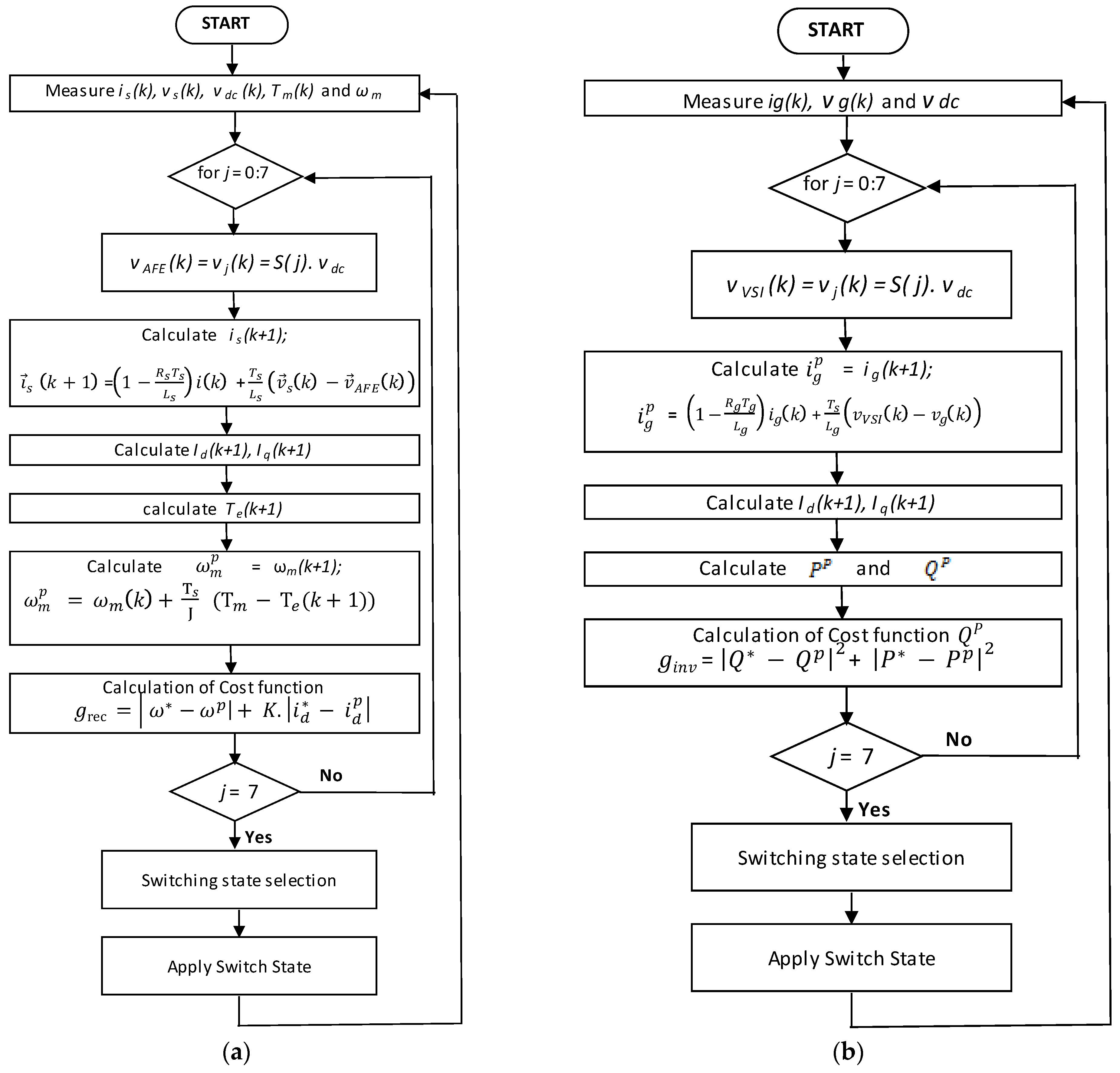
to select the switching state which minimizes the cost function. The error between d axis current reference and predicted d axis current is added to the cost function with an arbitrary constant K to reduce the d-axis current in the generator and thereby, avoid flux weakening. Figure 5a illustrates the proposed FCS-MPC control algorithm for the AFE rectifier [3].
4.3. Two-Level Voltage Source Inverter (2L-VSI) Model
As shown in Figure 1, the 2L-VSI inverter connects the DC link to the AC grid through the line filter inductances Lg = [(Lgu + Lfu), (Lgv + Lfv), (Lgw + Lfw)]T and resistances Rg = [(Rgu + Rfu), (Rgv + Rfv), (Rgw + Rfw)]T. This is designed to control the output active and reactive power as required by the grid code [31,45,47]. 2L-VSI’s IGBT switches are operated in a similar manner as the AFE rectifiers. The inverter switching state is determined by the gating signals Su, Sv and Sw.
The relationship between the grid three phase AC voltage and inverter input voltage vectors are obtained by applying Kirchhoff’s voltage law to the output side of the 2L-VSI as:
where is the grid voltage and is the grid current. The input current dynamics of the 2L-VSI is written as [32]:
4.4. FCS-MPC for 2L-VSI
The proposed control structure is designed to minimize the errors between reference power and predictive power. The errors between active power denoted respectively by and and errors between reactive power denoted respectively by and . The reference power values are fixed for the 2L-VSI according to the TSO requirements. In the control system, the future value of and is calculated using future current which is . This is calculated from (29) for each one of eight possible switching vectors (). Then the and is converted into dq rotating reference frame denoted as , , , to calculate predictive power values using equations (12) and (13) before they are compared to the reference power value to select the switching state which minimise the cost function as [31,32]:
Figure 5b illustrates the proposed FCS-MPC control algorithm for the 2L-VSI.
5. Simulation Results and Discussion
Simulations were carried out using the Matlab/Simulink software to evaluate and confirm the performance of the proposed FCS-MPC. The parameters given in Table 2 are used to design the PMSG, filters and dc link. The generator and battery parameters are taken from [39,48], respectively. The simulation results shown in Figure 6 are used to evaluate the FCS–MPC performance of the AFE rectifier. The performance of the storage system and its ability to uphold the supply power to a set value is evaluated by simulation results shown in Figure 7. The simulation results shown in Figure 8, are used to evaluate the FCS-MPC performance of 2L-VSI.
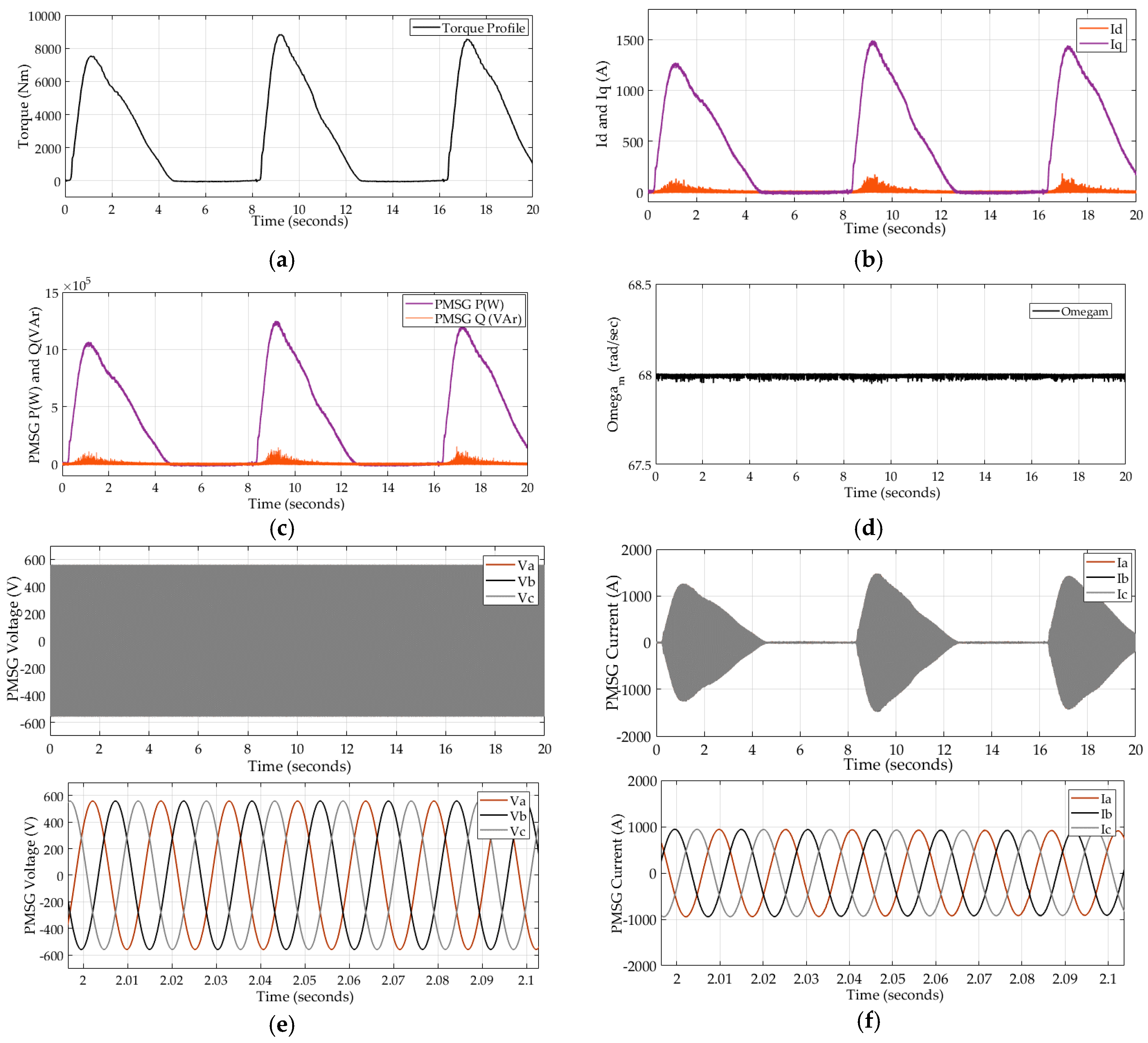
The torque profile obtained from the research data from [7] which is used as the mechanical input to the PMSG is shown in Figure 6a. Figure 6b, shows the stator current in dq rotational reference frame. The d-axis current remains closer to zero while the q-axis current varies in proportion to the torque input. This variation of the q-axis current directly affects the active power drawn from the generator which also varies in proportion to the torque as shown in Figure 6c.
This figure also illustrates the generator’s reactive power which is maintained at zero. Figure 6d confirms that the rotor angular speed is following the reference value 68 rad/s which is set as the target operating conditions of the air turbine. Figure 6e,f illustrate the PMSG’s output voltage and current respectively which are nearly sinusoidal. The MPC controller maintains the voltage input at a nearly constant level to the rectifier while current varies according to the power input. These results confirm the ability of the proposed controller to extract power from OWC air turbine under varying input torque.
Figure 7a depicts the dc-link voltage which varies within a small range (5%) in proportion to the power captured by the turbine. Figure 7b shows dc-link current and battery current, which vary with the input power. The battery current remains within its charge and discharge currents limits and thus these results confirm that the battery power is indirectly controlled by the rectifier controller and inverter controller. Figure 7c illustrates the percentage of the battery’s SoC which remains nearly at an initial value with about 0.03% variation for the given sea conditions. These results show that battery charges when the input power is higher than the set power output and discharges when the input power is lower. Therefore, the proposed battery direct-connection method and the control technology are able to deliver smooth power output to the grid without going into unstable conditions under varying input power conditions.
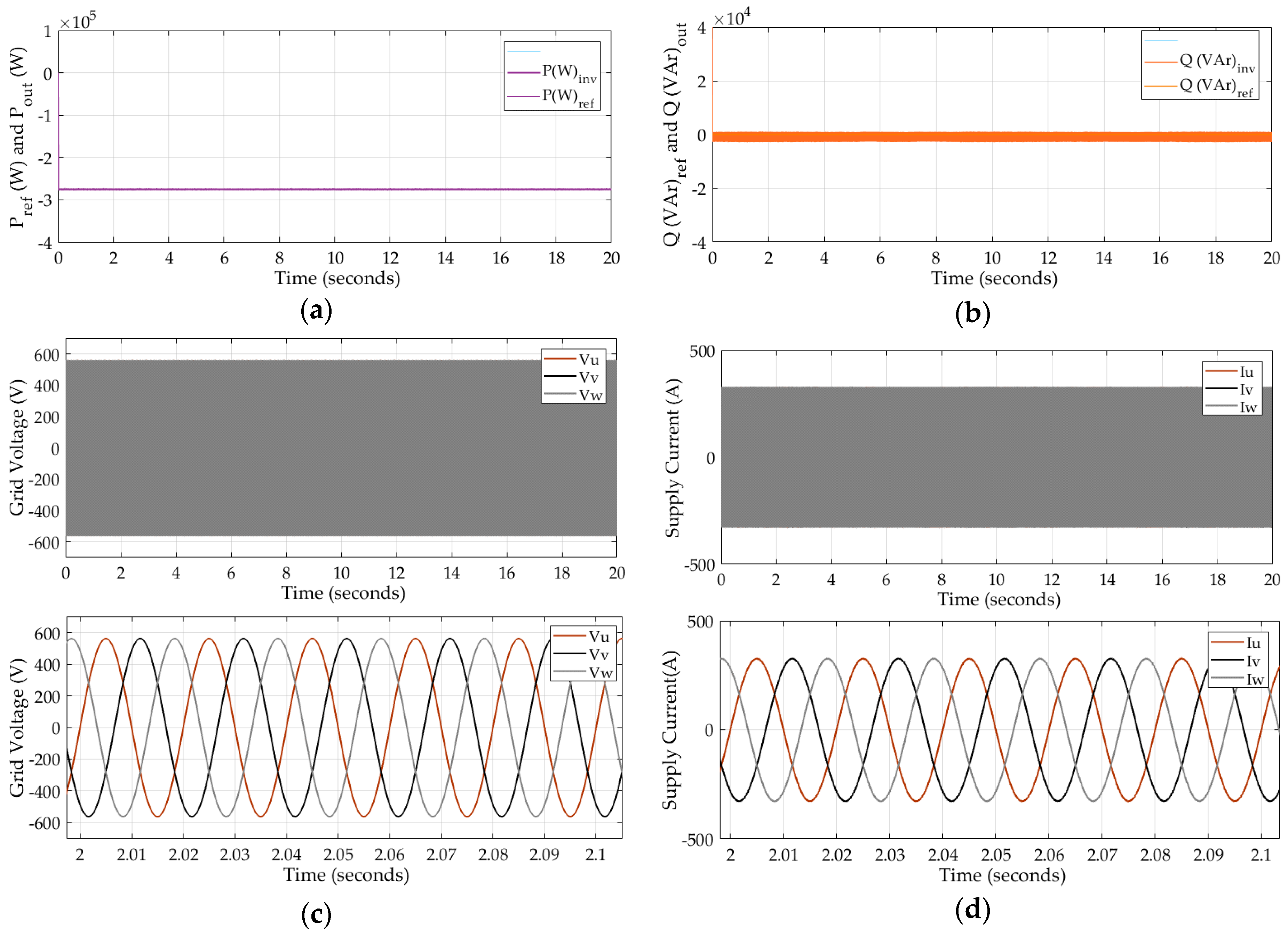
Figure 8a,b shows the active and reactive power supplied to the grid, respectively. The figures depict smooth power output with almost 0% deviation from the set power refernces. Figure 8c,d confirms that the 3-phase output voltage and current are in-phase and the THD of the three phase currents (Iuvw) is around 0.68% which is much lower than the IEEE standards (5%) [49]. These results depict the ability of the proposed MPC to deliver the constant and quality power to the ac grid under varying dc-link voltages.
6. Conclusions
This paper proposes a FCS-MPC strategy for electrical power control of OWC air turbine generators which uses a back-to-back power converter system and Li-ion BESS directly connected to the dc-link. Simulation results confirmed that the proposed control strategy along with the direct-connected BESS enable smooth power delivery to the grid. The FCS-MPC applied to the AFE rectifier is able to control the speed of the turbine at the set point of 68 rad/sec to maintain the air turbine within its optimum efficiency range under varying wave conditions. The 2L-VSI’s FCS-MPC is able to maintain the output power, minimising the error between the set point and the supply. The Li-ion BESS helps improve the smooth power delivery to the grid by absorbing fluctuations present in the input power. The THD of the output current is below the grid code requirement of 5%. The battery charge and discharge currents are indirectly controlled by the controllers of the back-to-back power converter system to remain within safe operating limits. In overall, the proposed electrical power conversion system has confirmed its ability to improve the quality of power supply to match the grid codes irrespective of the intermittencies present in the extracted power from the waves under varying wave conditions. Although the results obtained from this study are very promising, further investigations and implementations are required for experimental validations and the development of an adaptive system against parameter variations.
Acknowledgments
The authors thank Wave Swell Energy for providing the parameters to use in the simulation studies.
Author Contributions
Gimara Rajapakse and Shantha Jayasinghe conceived and designed the simulator model and analyzed the data; Gimara Rajapakse wrote the paper; Shantha Jayasinghe, Alan Fleming and Michel Negnevitsky critically reviewed the paper.
Conflicts of Interest
The authors declare no conflict of interest.
References
- Carson, L.; Bradshaw, M.; Jaques, L.; Che, N.; Ball, A. Australian Energy Resource Assessment 2010; Commonwealth of Australia (Geoscience Australia): Canberra, Australia, 2010. [Google Scholar]
- Carson, L.; Bradshaw, M.; Jaques, L. Australian Energy Resource Assessment 2014, 2nd ed.; Commonwealth of Australia (Geoscience Australia): Canberra, Australia, 2014. [Google Scholar]
- Rajapakse, G.; Jayasinghe, S.G.; Fleming, A.; Shahnia, F. Model Predictive Control-based Power take-off Control of an Oscillating Water Column Wave Energy Conversion System. In Proceedings of the 2017 International Conference on Substantial Energy Engineering (ICSEE 2017), Perth, Australia, 12–14 June 2017. [Google Scholar]
- Stegman, A.; de Andres, A.; Jeffrey, H.; Johanning, L.; Bradley, S. Exploring Marine Energy Potential in the UK Using a Whole Systems Modelling Approach. Energies 2017, 10, 1251. [Google Scholar] [CrossRef]
- Delmonte, N.; Barater, D.; Giuliani, F.; Cova, P.; Buticchi, G. Review of Oscillating Water Column Converters. IEEE Trans. Ind. Appl. 2016, 52, 1698–1710. [Google Scholar] [CrossRef]
- Hannon, M.; Griffiths, J.; Vantoch-Wood, A.; Carcas, M.; Bradley, S.; Boud, R.; Wyatt, S. World Energy Resources; Marine Energy 2016; World Energy Council; World Energy Resources: London, UK, 2016. [Google Scholar]
- Wave Swell Energy. Sustainable Elecricity from the Ocean. Available online: http://waveswellenergy.com.au/ (accessed on 27 March 2017).
- Fleming, A.; MacFarlane, G.; Hunter, S.; Denniss, T. Power Performance Prediction for a Vented Oscillating Water Column Wave Energy Converter with a Unidirectional Air Turbine Power Take-off. In Proceedings of the 12th European Wave and Tidal Energy Conference (EWTEC), Cork, Ireland, 27 August–1 September 2017. [Google Scholar]
- Falcao, A.F.O.; Henriques, J.C.C. Oscillating-water-column wave energy converters and air turbines: A review. Renew. Energy 2015, 85, 1391–1424. [Google Scholar] [CrossRef]
- Oceanlinx. Available online: http://www.oceanlinx.com/ (accessed on 27 March 2017).
- Tedeschi, E.; Carraro, M.; Molinas, M.; Mattavelli, P. Effect of Control Strategies and Power Take-Off Efficiency on the Power Capture From Sea Waves. IEEE Trans. Energy Convers. 2011, 26, 1088–1098. [Google Scholar] [CrossRef]
- Heier, S. Grid Integration of Wind Energy; John Wiley & Sons Ltd: Chichester, UK, 2014. [Google Scholar]
- Wu, Q.; Xu, Z.; Østergaard, J. Grid Integration Issues for Large Scale Wind Power Plants (WPPs). In Proceedings of the Power and Energy Society General Meeting (IEEE PES GM 2010), Providence, RI, USA, 25–29 July 2012; pp. 1–6. [Google Scholar]
- Zou, Y.; Cheng, K.W.E. A Vertical Flux-Switching Permanent Magnet Based Oscillating Wave Power Generator with Energy Storage. Energies 2017, 10, 887. [Google Scholar] [CrossRef]
- Ceballos, S.; Rea, J.; Robles, E.; Lopez, I.; Pou, J.; O’Sullivan, D.L. Control strategies for combining local energy storage with wells turbine oscillating water column devices. Renew. Energy 2015, 83, 1097–1107. [Google Scholar] [CrossRef]
- Vilathgamuwa, M.; Nayanasiri, D.; Gamini, S. Power Electronics for Photovoltaic Power Systems; Hudgins, J., Ed.; Morgan & Claypool Publishers: San Rafael, CA, USA, 2015. [Google Scholar]
- Guerrero, J.M.; Vasquez, J.C.; Matas, J.; De Vicuña, L.G.; Castilla, M. Hierarchical Control of Droop-Controlled AC and DC Microgrids—A General Approach Toward Standardization. IEEE Trans. Ind. Electron. 2011, 58, 158–172. [Google Scholar] [CrossRef]
- Mehrasa, M.; Adabi, M.E.; Pouresmaeil, E.; Adabi, J. Passivity-based control technique for integration of DG resources into the power grid. Int. J. Electr. Power Energy Syst. 2014, 58, 281–290. [Google Scholar] [CrossRef]
- Mehrasa, M.; Pouresmaeil, E.; Akorede, M.F.; Jørgensen, B.N.; Catalao, P.S. Multilevel converter control approach of active power filter for harmonics elimination in electric grids. Energy 2015, 84, 722–731. [Google Scholar] [CrossRef]
- Mehrasa, M.; Rezanejhad, M.; ouresmaeil, E.; Catalão, P.S.; Zabihi, S. Analysis and control of single-phase converters for integration of small-scaled renewable energy sources into the power grid. In Proceedings of the 7th Power Electronics, Drive Systems & Technologies Conference (PEDSTC 2016), Tehran, Iran, 16–18 February 2016. [Google Scholar]
- Rodriguez, J.; Cortés, P. Predictive Control Of Power Converters and Electrical Drives; John Wiley & Sons Ltd: Chichester, UK, 2012. [Google Scholar]
- Sultana, W.R.; Sahoo, S.K.; Sukchai, S.; Yamuna, S.; Venkatesh, D. A review on state of art development of model predictive control for renewable energy applications. Renew. Sustain. Energy Rev. 2017, 76, 391–406. [Google Scholar] [CrossRef]
- Tarisciotti, L.; Zanchetta, P.; Watson, A.; Clare, J.C.; Degano, M.; Bifaretti, S. Modulated Model Predictive Control for a Three-Phase Active Rectifier. IEEE Trans. Ind. Appl. 2015, 51, 1610–1620. [Google Scholar] [CrossRef]
- Nguyen, T.H.; Kim, K.H. Finite Control Set–Model Predictive Control with Modulation to Mitigate Harmonic Component in Output Current for a Grid-Connected Inverter under Distorted Grid Conditions. Energies 2017, 10, 907. [Google Scholar] [CrossRef]
- Abdelrahem, M.; Hackl, C.; Kennel, R. Model Predictive Control of Permanent Magnet Synchronous Generators in Variable-Speed Wind Turbine Systems. In Proceedings of the Power and Energy Student Summit 2016 (PESS 2016), Aachen, Germany, 19–20 January 2016. [Google Scholar]
- Lekube, J.; Garrido, A.J.; Garrido, I. Rotational Speed Optimization in Oscillating Water Column Wave Power Plants Based on Maximum Power Point Tracking. IEEE Trans. Autom. Sci. Eng. 2017, 14, 681–691. [Google Scholar] [CrossRef]
- Clean Energy Council. Renewable Energy—Marine Energy. Available online: https://www.cleanenergycouncil.org.au/technologies/marine-energy.html (accessed on 17 February 2017).
- Tasnetworks. TasNetworks Annual Planning Report 2016; Tasmanian Networks Pty Ltd (TasNetworks): Lenah Valley, Australia, 2016. [Google Scholar]
- The King Island Renewable Energy Integration Project (KIREIP). Available online: http://www.kingislandrenewableenergy.com.au/project-information/overview (accessed on 24 May 2017).
- Bimbhra, P.S. Generalized Theory of Electrical Machines; Khanna Publishers: Delhi, India, 1992. [Google Scholar]
- Rodriguez, J.; Kazmierkowski, M.P.; Espinoza, J.R.; Zanchetta, P.; Abu-Rub, H.; Young, H.A.; Rojas, C.A. State of the Art of Finite Control Set Model Predictive Control in Power Electronics. IEEE Trans. Ind. Inform. 2013, 9, 1003–1016. [Google Scholar] [CrossRef]
- Parvez, M.; Tan, N.M.L.; Akagi, H. An Improved Active-Front-End Rectifier Using Model Predictive Control. In Proceedings of the IEEE Applied Power Electronics Conference and Exposition (APEC), Charlotte, NC, USA, 15–19 March 2015; pp. 122–127. [Google Scholar]
- Krishnan, R. Permanent Magnet Synchronous and Brushless DC Motor Drives; Taylor & Francis Group: London, UK, 2010. [Google Scholar]
- Modeling of a Variable Speed Wind Turbine with a Permanent Magnet Synchronous Generator. In Proceedings of the IEEE International Symposium on Industrial Electronics (ISlE 2009), Seoul, Korea, 5–8 July 2009.
- Hughes, M.G.; Heap, A.D. National-scale wave energy resource assessment for Australia. Renew. Energy 2009, 35, 1783–1791. [Google Scholar] [CrossRef]
- Kempener, R.; Borden, E. Battery Storage for Renewables: Market Status and Technology Outlook; The International Renewable Energy Agency (IRENA): Masdar City, UAE, 2015. [Google Scholar]
- Leuchter, J. Bi-Directional DC—DC Converters for Battery Buffers with Supercapacitor. In Energy Storage in the Emerging Era of Smart Grids; InTech: Rijeka, Croatia, 2011. [Google Scholar]
- Kim, J.; Suharto, Y.; Daim, T.U. Evaluation of Electrical Energy Storage (EES) technologies for renewable energy: A case from the US Pacific Northwest. J. Energy Storage 2017, 11, 25–54. [Google Scholar] [CrossRef]
- PBES Power and Energy Industrial Lithium Batteries. In PBES Specification Sheet System Specifications for the PBES Power & Energy Systems; Storage, P.B.E. (Ed.) Plan B Energy Storage: Vancouver, BC, Canada; Trondheim, Norway; Barcelona, Spain; Copenhagen, Denmark, 2017. [Google Scholar]
- Power Module; Scalable and Modular Lithium-Ion Energy Storage System. Available online: https://www.powertechsystems.eu/wp-content/uploads/2016/05/Fiche-Produit-PowerModule_EN.pdf (accessed on 1 August 2017).
- Thirugnanam, K.; Joy, E.R.T.P.; Singh, M.; Kumar, P. Mathematical Modeling of Li-Ion Battery Using Genetic Algorithm Approach for V2G Applications. IEEE Trans. Energy Convers. 2014, 29, 332–343. [Google Scholar]
- Rahmoun, A.; Biechl, H. Modelling of Li-ion batteries using equivalent circuit diagrams. Prz. Elektrotech. (Electr. Rev.) 2012, 152–156. [Google Scholar]
- Vazquez, S.; Leon, J.I.; Franquelo, L.G.; Rodriguez, J.; Young, H.A.; Marquez, A.; Zanchetta, P. Model Predictive Control: A Review of Its Applications in Power Electronics. IEEE Ind. Electron. Mag. 2014, 8, 16–31. [Google Scholar] [CrossRef] [Green Version]
- Texas Instruments. TMS320F2837xS Delfino™ Microcontrollers; Texas Instruments: Dallas, TX, USA, 2015. [Google Scholar]
- Liu, Z.; Wang, D.; Peng, Z. A Simplified Direct Finite-Control-Set Model Predictive Control for AFEs with DC-Link Voltage Dynamic Reference Design. In Proceedings of the 35th Chinese Control Conference (CCC), Chengdu, China, 27–29 July 2016; pp. 4294–4299. [Google Scholar]
- Quevedo, D.E.; Aguilera, R.P.; Pérez, M.A.; Cortés, P.; Lizana, R. Model Predictive Control of an AFE Rectifier With Dynamic References. IEEE Trans. Power Electron. 2012, 7, 3128–3136. [Google Scholar] [CrossRef]
- Parvez, M.; Mekhilef, F.; Tan, M.L.N.; Akagi, H. A Robust Modified Model Predictive Control (MMPC) Based on Lyapunov Function for ThreePhase Active-Front-End (AFE) Rectifier. In Proceedings of the 2016 IEEE Applied Power Electronics Conference and Exposition (APEC), Long Beach, CA, USA, 20–24 March 2016; pp. 1163–1168. [Google Scholar]
- Permanent Magnet Generator Quotation Sheet. Qingdao Greef New Energy Equipment; Greef Energy: Qingdao, China, 2017. [Google Scholar]
- Langella, R.; Testa, A. IEEE Recommended Practice and Requirements for Harmonic Control in Electric Power System; University of Campania “Luigi Vanvitelli”: Caserta, Italy, 2014. [Google Scholar]
Figure 1.
Schematic diagram of the proposed oscillating water column (OWC) air turbine generator—grid interface system.
Figure 1.
Schematic diagram of the proposed oscillating water column (OWC) air turbine generator—grid interface system.
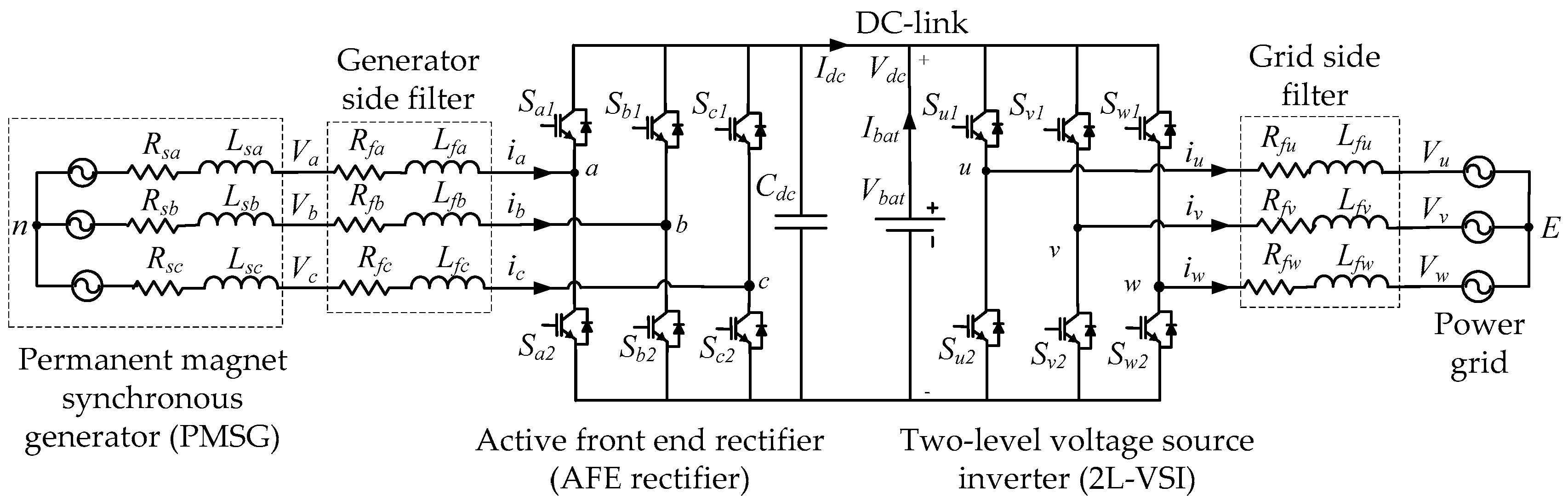
Figure 2.
Model scale experiments performed in the Australian Maritime College’s Model Test Basin [7].
Figure 2.
Model scale experiments performed in the Australian Maritime College’s Model Test Basin [7].
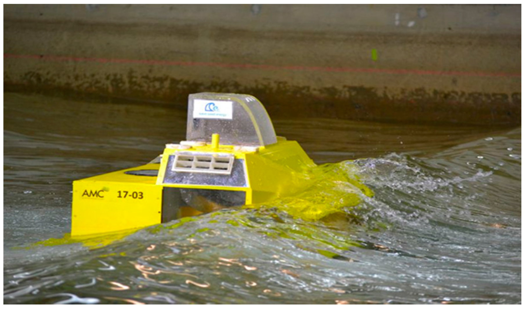
Figure 3.
(a) Predicted efficiency curve for the unidirectional air turbine designed for OWC project, extracted from the turbine design report by PerAero Turbine Designs [8]; (b) Pressure drop vs time at 650 rpm [8].
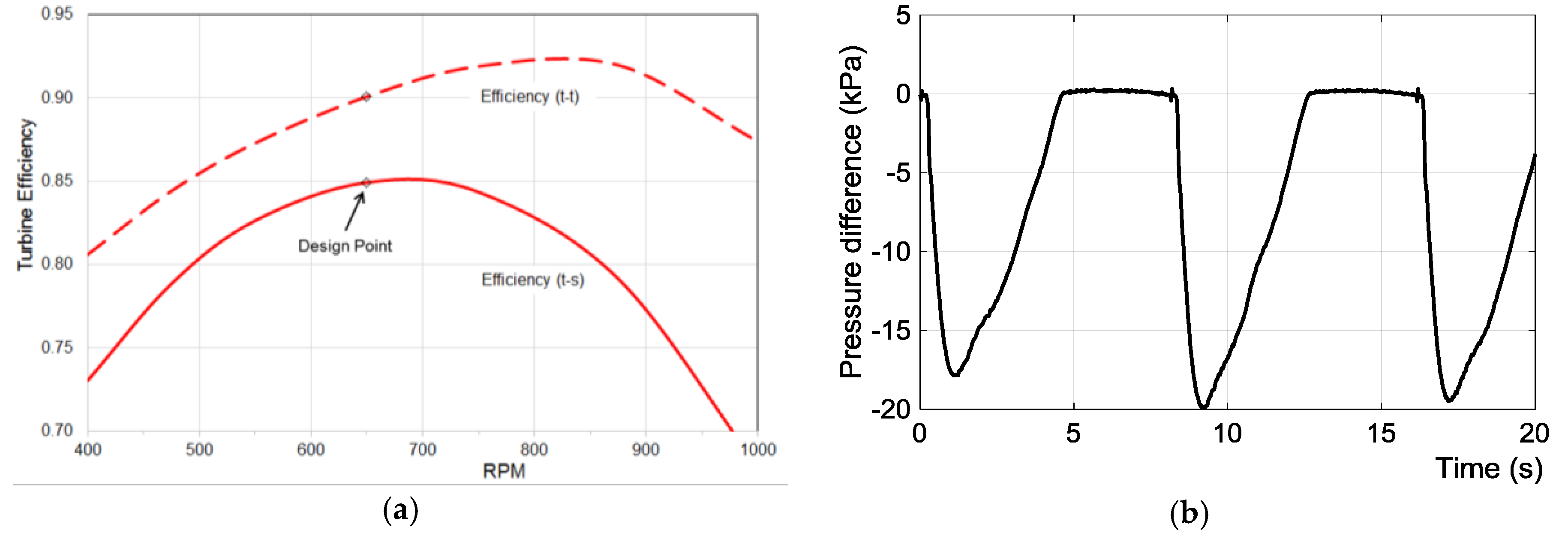
Figure 4.
Model predictive controller (MPC) for an active front end (AFE rectifier) rectifier and two-level voltage source inverter.
Figure 4.
Model predictive controller (MPC) for an active front end (AFE rectifier) rectifier and two-level voltage source inverter.
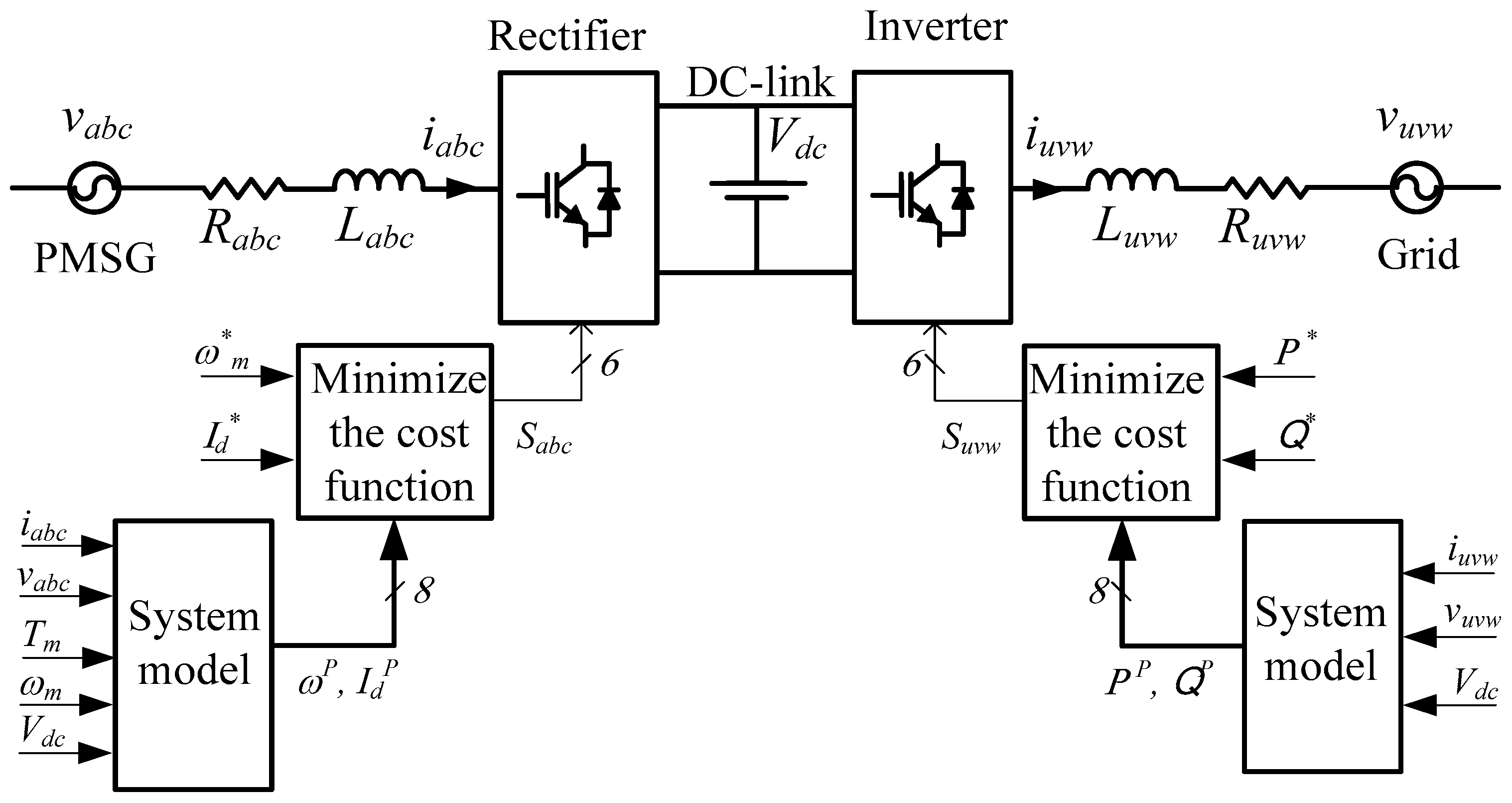
Figure 5.
(a) MPC algorithm flow chart for the AFE rectifier; (b) MPC algorithm flow chart for the grid-connecting 2L-VSI Inverter.
Figure 5.
(a) MPC algorithm flow chart for the AFE rectifier; (b) MPC algorithm flow chart for the grid-connecting 2L-VSI Inverter.

Figure 6.
The FCS-MPC performance of AFE rectifier: (a) Mechanical torque profile; (b) PMSG stator current in dq rotational reference frame; (c) Generator active power P (W) and reactive power Q (VAr); (d) Generator rotor angular speed m (rad/sec); (e) Generator peek voltage Vpk (V); (f) Generator peek current Ipk (A).

Figure 7.
The performance of energy storage and the dc-link: (a) dc link voltage dc (V); (b) dc link current Idc (A) and battery current Ibat (V); (c) state of charge of the battery SoC%.
Figure 7.
The performance of energy storage and the dc-link: (a) dc link voltage dc (V); (b) dc link current Idc (A) and battery current Ibat (V); (c) state of charge of the battery SoC%.
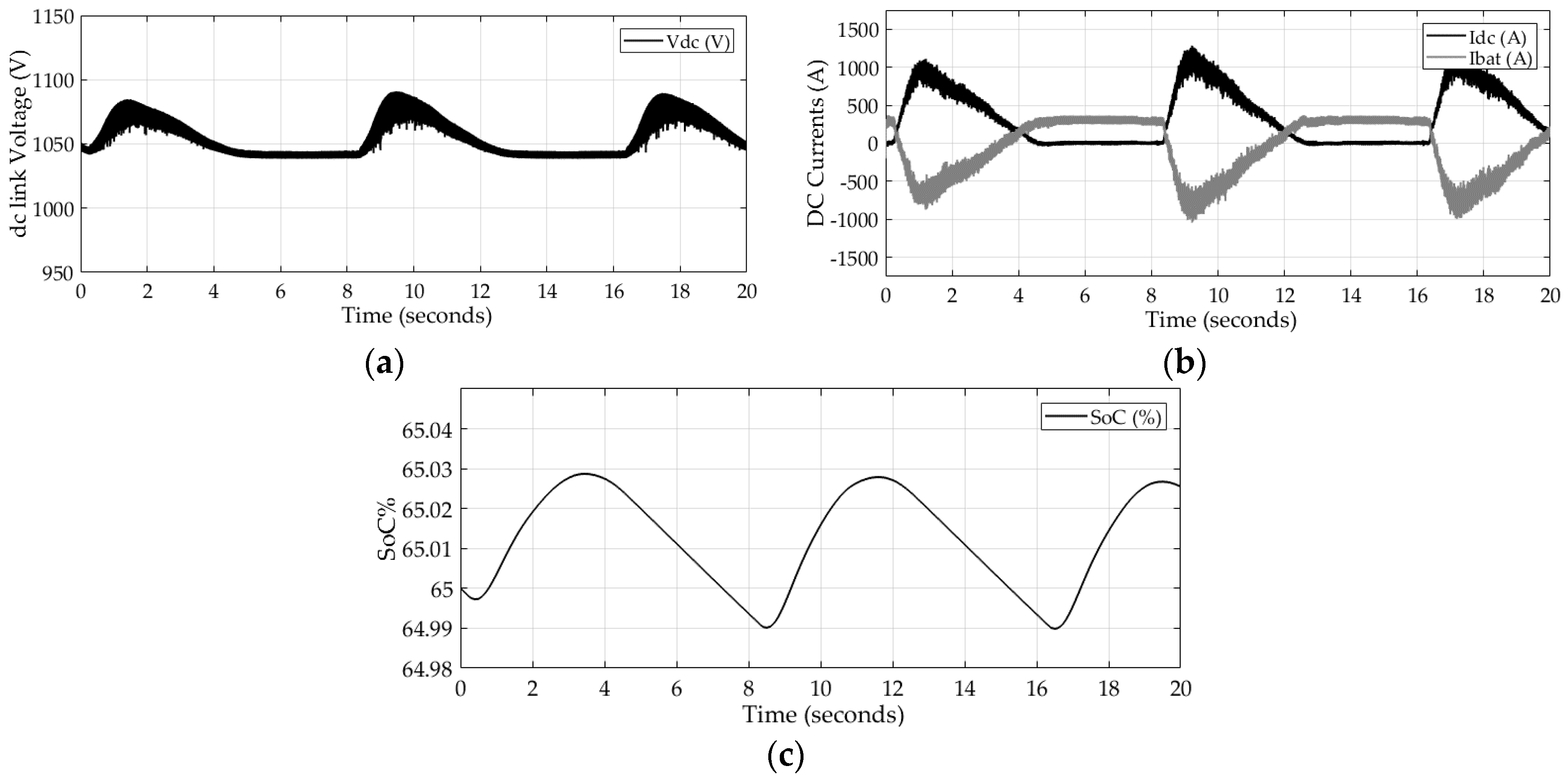
Figure 8.
The FCS–MPC performance of 2L-VSI: (a) Active power output to the grid P (W); (b) Reactive power output to the grid Q (VAr); (c) Grid peek voltage Vpk (V); (d) Grid peek current Ipk (A).
Figure 8.
The FCS–MPC performance of 2L-VSI: (a) Active power output to the grid P (W); (b) Reactive power output to the grid Q (VAr); (c) Grid peek voltage Vpk (V); (d) Grid peek current Ipk (A).


Table 1.
Switching states and voltage space vectors of three phase voltage source.
| Switching States | Voltage Space Vector | ||
|---|---|---|---|
| Sa | Sb | Sc | |
| 0 | 0 | 0 | |
| 1 | 0 | 0 | |
| 1 | 1 | 0 | |
| 0 | 1 | 0 | |
| 0 | 1 | 1 | |
| 0 | 0 | 1 | |
| 1 | 0 | 1 | |
| 1 | 1 | 1 | |
Table 2.
System parameters used in the design.
| PMSG | Generator Side Filter | ||
|---|---|---|---|
| Rated Power | 2 MW | Inductance | 0.5 mH |
| Rated rotate speed | 650 rpm | Resistance | 0.01 Ω |
| Rated Voltage | 690 VAC | dc-link | |
| Rated current | 1673.5 A | Capacitance (Cdc) | 470 mF |
| Number of pole pairs | 6 | dc-link voltage | ~1000 V |
| Resistance (Rs) | 0.0024 Ω | Grid side Filter | |
| Inductances (Ld = Lq) | 0.355 mH | Inductance | 1 mH |
| Magnetic flux () | 0.666 Wb | Resistance | 0.1 Ω |
| Li-ion battery storage | Grid | ||
| Nominal voltage/Fully charged voltage | 1000 V/1050 V | - | - |
| Rated capacity @ nominal voltage | 150 Ah (75 Ah × 2) | Voltage | 690 Vrms |
| Rated current @ nominal voltage | 900 A (450 A × 2) | Frequency | 50 Hz |
| Initial state of charge in % | 65% | Other | |
| Reference Values | Sample time | 10−5 s | |
| Active Power | 270 kW | Simulator run-time | 20 s |
| Reactive Power | 0 | Total Inertia (J) | 0.25 kgm2 |
© 2017 by the authors. Licensee MDPI, Basel, Switzerland. This article is an open access article distributed under the terms and conditions of the Creative Commons Attribution (CC BY) license (http://creativecommons.org/licenses/by/4.0/).
Share and Cite
MDPI and ACS Style
Rajapakse, G.; Jayasinghe, S.; Fleming, A.; Negnevitsky, M. A Model Predictive Control-Based Power Converter System for Oscillating Water Column Wave Energy Converters. Energies 2017, 10, 1631. https://doi.org/10.3390/en10101631
AMA Style
Rajapakse G, Jayasinghe S, Fleming A, Negnevitsky M. A Model Predictive Control-Based Power Converter System for Oscillating Water Column Wave Energy Converters. Energies. 2017; 10(10):1631. https://doi.org/10.3390/en10101631
Chicago/Turabian StyleRajapakse, Gimara, Shantha Jayasinghe, Alan Fleming, and Michael Negnevitsky. 2017. "A Model Predictive Control-Based Power Converter System for Oscillating Water Column Wave Energy Converters" Energies 10, no. 10: 1631. https://doi.org/10.3390/en10101631
Note that from the first issue of 2016, this journal uses article numbers instead of page numbers. See further details here.