
Rapid Optimization of Double-Stators Switched Reluctance Motor with Equivalent Magnetic Circuit


Department of Mechanical and Automation Engineering, National Kaohsiung First University of Science and Technology, No.1, University Rd., Yanchao Dist., Kaohsiung City 824, Taiwan
Energies 2017, 10(10), 1603; https://doi.org/10.3390/en10101603
Submission received: 18 September 2017
/
Revised: 6 October 2017
/
Accepted: 11 October 2017
/
Published: 13 October 2017
Abstract
:The primary objective for this paper is to create a methodology to rapidly optimize double-stators switched reluctance motor (DSSRM). An analytical model of equivalent magnetic circuits for the air gap reluctances of aligned and unaligned positions is proposed and the optimal operation point of the magneto-motive force (MMF) can be determined. Genetic algorithm (GA) integrated of the proposed equivalent magnetic circuit is developed for rapid optimization of DSSRM to reach the maximum of the ratio of torque to volume of DSSRM. Compared to conventional switched reluctance motor (SRM), an illustrated example of a 3-KW three-phase 12-Slot-8-Pole DSSRM is used to verify the efficiency of the proposed method. Simplified 2-D electromagnetic models are analyzed and simulated. Finally, results of the analytical calculations and the finite-element analysis (FEA) are validated by the proposed motor to show the accuracy of the designed strategy.
1. Introduction
In recent years, switched reluctance motors (SRMs), as shown in Figure 1a, have been used for various applications such as aerospace industry, marine propulsion systems, linear drives, mining drives, handheld tools, home utilities, etc. The main reasons for using SRMs in these applications are low-cost construction characterized by an absence of magnets and rotor winding, fault tolerant power stage design, and high level of performance over wider range of speeds. In general, SRMs have drawbacks of vibration and acoustic noises to limit their applications. To increase power density of SRM requires smaller air gap to easily force the motor into a highly saturated mode. The major benefits of double-stators switched reluctance motor (DSSRM), as shown in Figure 1b, in comparison with the conventional SRM are higher torque/power density; higher force conversion efficiency; higher motional force with lower radial force; and larger effective air gap reluctance at unaligned position. Due to the double-stator mechanical design of DSSRM, the design consideration is more complicated than that of SRM. Therefore, some studies on the designing and analysis of DSSRM can be found recently. In [1], based on dissecting DSSRM into inner and outer rotor SRMs, a design strategy concentrating on power rating was proposed to calculate the dimensions of DSSRM. Both inner and outer rotor SRMs can be designed separately. In [2], an analytical model for the unaligned inductance of the SRM was developed. Both the contribution of the flux in the stator slot and the contribution of the flux in the rotor slot to the unaligned inductance were considered. In [3], the structural behavior of a DSSRM and a conventional SRM using a multi-physic analysis was compared. An electromagnetic finite-element method is used to calculate force density at various parts of the stator surface in both machines. In [4], thermal modeling and analysis of DSSRM were presented. A three-dimensional finite-element method (FEM) has been used to numerically calculate the temperature distribution in different parts of the machine. In [5], the design method of DSSRM is based on optimization of the motional forces, which leads to a high-grade electromechanical energy conversion process. A local examination of the force densities within and throughout a conventional SRM shows that the majority of the force produced is in the radial direction and does not contribute to motion. In [6], a design optimization of a double-stator switched reluctance machine was proposed for improving the magnetic torque quality of the machine. For this purpose, finite element method along with response surface methodology was used to optimize three parameters of the machine to maximize torque quality factor i.e., the average torque to torque ripple ratio in the machine. In [7], an effective rotor shaping optimization technique for torque ripple reduction of DSSRM was presented. This method leads to the lower torque pulsation without significant reduction in the average torque.
DSSRM has a novel, optimized pattern of magnetic flux paths within the electrical machine, which yields superior performance. As seen in existing studies, the torque density of DSSRM can be twice that of SRM. Double stators (outer stator and inner stator) of DSSRM can be used to reduce the radial force and noise during operation. The shell type rotor results in dramatically smaller inertia. Therefore, DSSRM maintains the fault tolerance and the wider speed range capability. From the references mentioned above, numerical solution of FEM applied to various characteristic analyses of DSSRM is adopted in most studies, while there are fewer details of air gap reluctances of aligned and unaligned positions. Therefore, this paper presents a mathematic modeling of DSSRM with equivalent magnetic circuit to precisely obtain the magnetic flux linkages of aligned and unaligned positions. This modeling is used to provide target equation of GA for rapidly optimization of DSSRM.
This paper is organized as follows. In Section 2, equivalent magnetic circuit of DSSRM is constructed to analyze the air gap flux linkages of aligned and unaligned positions, and the optimal operation point of the MMF is determined. Optimal design of DSSRM with GA, including of core material, winding setting, and machine arrangement, is performed in Section 3. The simplified 2D electromagnetic models are analyzed and simulated in Section 4. Finally, the conclusions are drawn in Section 5.
2. Equivalent Magnetic Circuit Analysis of DSSRM
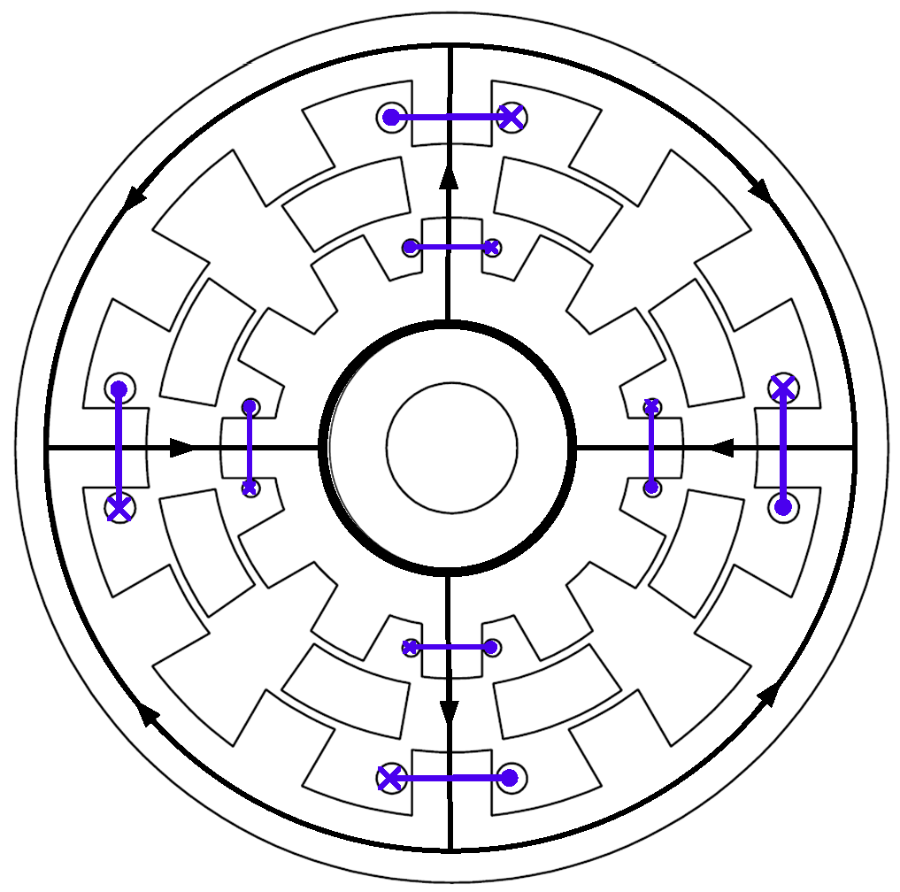
DSSRM is a novel SRM that is designed to perform at high torque levels. The cross section of a three-phase 12-Slot-8-Pole DSSRM is illustrated in Figure 2. DSSRM benefits from two stators, which are made of laminated ferromagnetic material and are equipped with concentrated windings. They are located on the interior and exterior of a cylindrical rotor. The rotor is formed by segments of laminated ferromagnetic material, which are held together using a non-ferromagnetic cage.
The electromagnetic torque of SRM is based on the inductance variation of the stator winding, which is a nonlinear function of stator current and rotor position. Practically, the inductance of the stator winding can be calculated by measuring the flux linkage. However, the magnetic flux linkage of the stator winding is difficult to measure directly in the case of DSSRM. Therefore, this paper exploits equivalent magnetic circuit of air gap to obtain the flux linkage curve, which is a function of rotor position. In general, SRM is a doubly salient brushless motor, with concentrated copper windings on the stator poles, and no windings or magnets on the rotor poles. Each phase is wound on diametrically opposite stator poles. Excitation of a phase, that is, excitation of a pair of diametrically opposite stator poles, causes the nearest pair of rotor poles to align with the excited stator poles. This produces torque regardless of the direction of the current in the phase winding. Therefore, only unipolar currents are required in stator phases, and sequential excitation based on rotor position causes the rotor to rotate and align its poles with the excited stator poles. In the following, the magnetic flux linkages of aligned and unaligned positions are analyzed, and their equivalent magnetic circuits are derived.
2.1. Calculated Magnetic Flux Linkage of Aligned Position
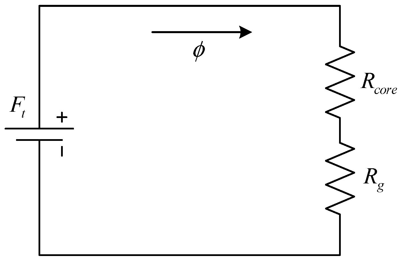
Figure 2 shows the magnetic flux of the single phase of DSSRM to align with the excited stator pole. The equivalent magnetic circuit of Figure 2 is described in Figure 3, where is core reluctance of the outer stator; is core reluctance of the inner stator; is core reluctance of the rotor; is reluctance of the outer air gap; is reluctance of the inner air gap; is MMF of the outer stator; is MMF of the inner stator; and , , , and are the magnetic fluxes of each loop.
Assuming , Equations (1)–(4) can be integrated as
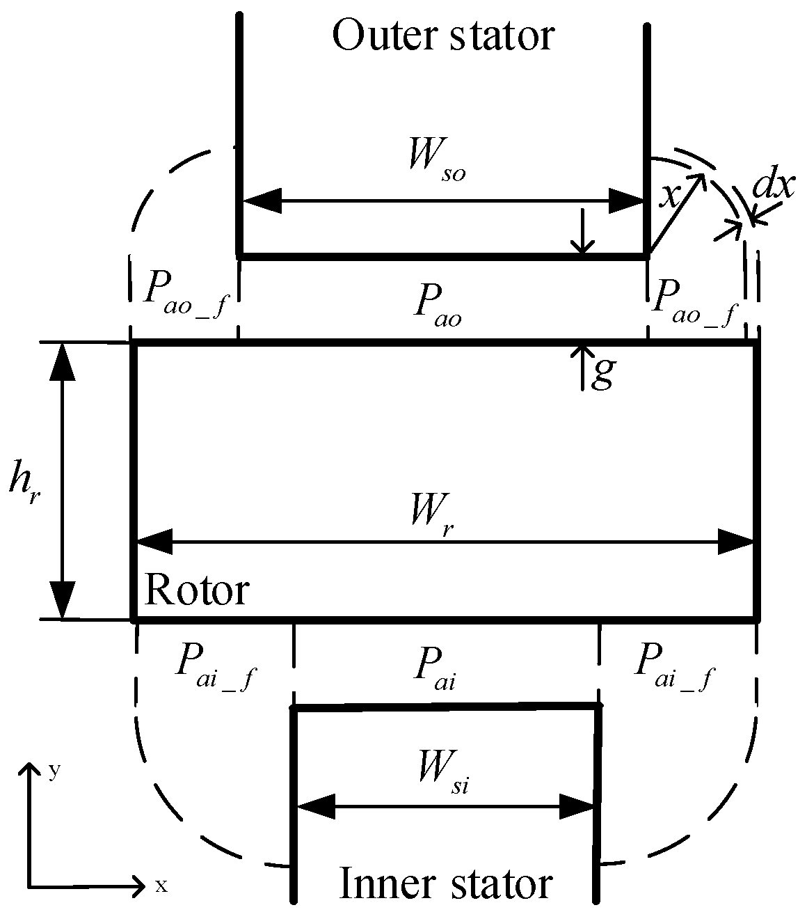
The permeance distribution for the rotor to align its poles with the excited stator poles is shown in Figure 4, where is salient pole width of the outer stator; is salient pole width of the inner stator; is block rotor width; and is air gap width. Considering fringing effect, the permeances, i.e., and , of the rotor to align its poles with the outer and inner stator poles can be given as, respectively,
where is vacuum permeability coefficient; and and are cross sections of salient poles of outer stator and inner stator, respectively.
Due to relative permeability coefficient of stator core being finite, for magnetic flux passing through air gap by air gap width expansion, the fringing effect should be considered. The circular-arc straight-line permeance model is often used for modeling the flux flow in the air gap [8]. Therefore, to calculate relative permeability coefficient of stator core under the fringing effect, this paper uses circular-arc straight-line modeling to calculate the permeances ( and ) of inner and outer stator cores, respectively, i.e.,
where is thickness of coiled silicon steel sheet.
Due to permeance distribution of inner and outer air gaps being parallel connection type, the reluctances ( and ) of outer and inner air-gaps can be obtained by, respectively,
The core reluctances (, , and ) of outer and inner stators and rotor can be obtained as, respectively,
where is permeability coefficient of core; , , and are magnetic flux lengths of outer stator, inner stator, and rotor, respectively; and is the cross-sectional area of segmented rotor. Then, Equations (10)–(14) can be substituted into Equation (5) to calculate magnetic linkage of air gap. To calculate the MMF at align position, a magnetic circuit with single excited phase is given as shown in Figure 5. Then, the total MMF of can be given as:
where is total reluctance of iron core and is total reluctance of air gap. Then, the magnetic potential drop of can be given by:
In addition, the magnetic potential drop can be obtained by magnetic field intensity from the material B-H curve multiplied by the length of magnetic path of the iron core, i.e.,
From Equations (16) and (17), we have
or
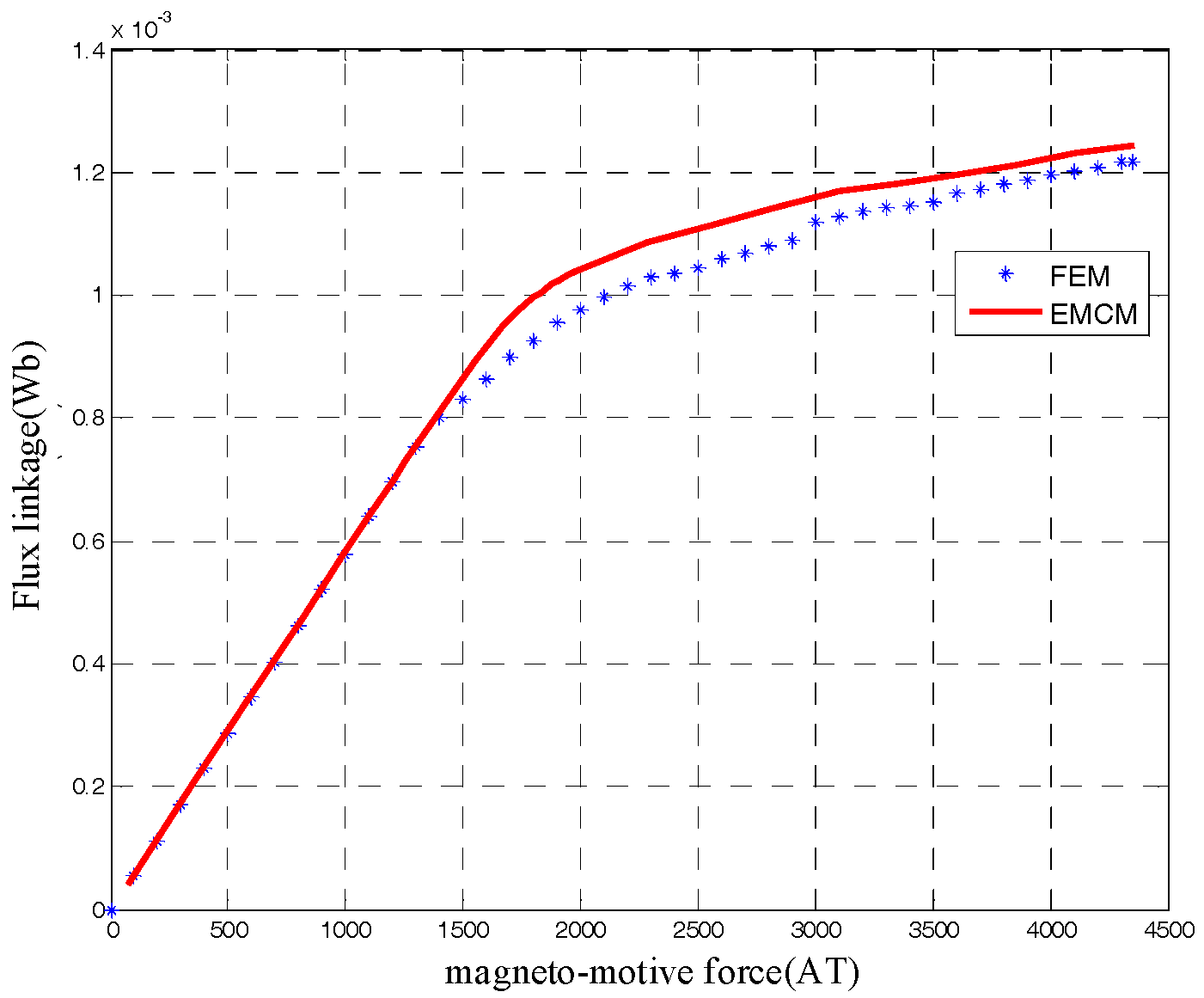
Figure 6 can be used to verify the accuracy of the analytical solution (19) and to compare the numerical solution of FEM. In Figure 6, larger MMF range is close to the magnetic saturation area of the stator under aligned position. Therefore, some discrepancy in the large MMF range of Figure 6 can be found. In this case, the optimal MMF of the proposed DSSRM is designed as about 1500 AT, which is located at non-magnetic saturation area. Therefore, the proposed equivalent magnetic circuit model of Figure 3 can be used to accuracy design DSSRM.
2.2. Calculated Magnetic Flux Linkage of Unaligned Position
Figure 7 shows the magnetic flux path of the single phase of DSSRM at unaligned position. It can be found that air gap width and length of unaligned position are larger than that of aligned position and irregular shape of air gap can also be found. Therefore, it is difficult to calculate the unaligned reluctance. In this work, considering the superposition of the linear system, the magnetic linkages generated by outer and inner excited stator are analyzed separately, and then, the results can be merged.
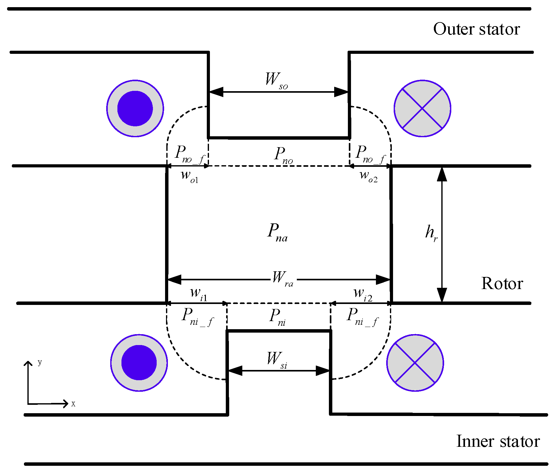
Considering fringing effect, completely unaligned position between stators and rotor is shown in Figure 8, where is rotor slot width; is fringing permeance of air gap of inner stator; is fringing permeance of air gap of outer stator; is permeance of air gap of rotor slot; is permeance of air gap between inner stator and rotor slot; and is permeance of air gap between outer stator and rotor slot.
Compared to the permeability coefficient of air gap at completely unaligned position, the permeability coefficient of iron core in Figure 8 can be assumed as infinite, and the magnetic potential drop of iron core can approach zero. Therefore, we can have the boundary condition of the magnetic field intensity of the rotor slots as shown in Figure 9. Assume that the boundary condition of rotor slot does not include the exciting current. Then, we have Laplacian operator of as:
where is rotor slot magnetic potential of z direction.
Here, to analyze boundary conditions of the magnetic field, intensity of the outer and inner stators can be used to calculate the flux linkage of rotor slot.
2.3. Calculated Flux Linkage of Outer Stator Excited
The boundary condition of the magnetic field intensity of the outer stator is shown in Figure 10. The magnetic potential of z direction can be given as:
where can be determined by magnetic field intensity distribution of the boundary at , and can be given as Equation (22) and Figure 11, i.e.,
where is winding turns of outer stator and is input current.
Due to windings of the stator being repeatability, Equation (22) can be expressed as a periodic function, i.e.,
where
and
The mathematic relation of magnetic flux density and magnetic potential vector can be given as:
where is defined as the curl operator of .
Therefore, from Equation (26), the magnetic field intensity can be obtained as:
As , Equation (23) is equal to (27), thus we have
From Equations (27) and (28), the magnetic flux density to flow through the core surface vertically can be given as:
By integrating Equation (29) along y direction, the magnetic flux can be obtained as:
2.4. Calculated Flux Linkage of Inner Excited Stator
The boundary condition of the magnetic field intensity of the inner stator is shown in Figure 12. The magnetic potential of z direction can be given as:
can be determined by magnetic field intensity distribution of the boundary at , which can be given as Equation (32) and shown in Figure 13, i.e.,
where is winding turns of inner stator.
Therefore, from Equation (26), the magnetic field intensity can be obtained as:
As , Equation (33) is equal to (36), thus we have
From Equations (36) and (37), the magnetic flux density of vertical through the core surface can be given as:
By integrating Equation (38) along y direction, the magnetic flux can be obtained as:
Based on Equations (39) and (30), the permeance of the air gap can be given as:
The permeances of air gap between stator and rotor slot and can be given as:
The fringing permeance of air gap of inner stator and outer stator can be given as:
The equivalent magnetic circuit of completely unaligned position between stator and rotor in Figure 8 can be drawn as Figure 14, where the total reluctance can be given as:
Total magnetic potential from inner and outer excited stators can be obtained as:
2.5. Optimal Operation Point of MMF
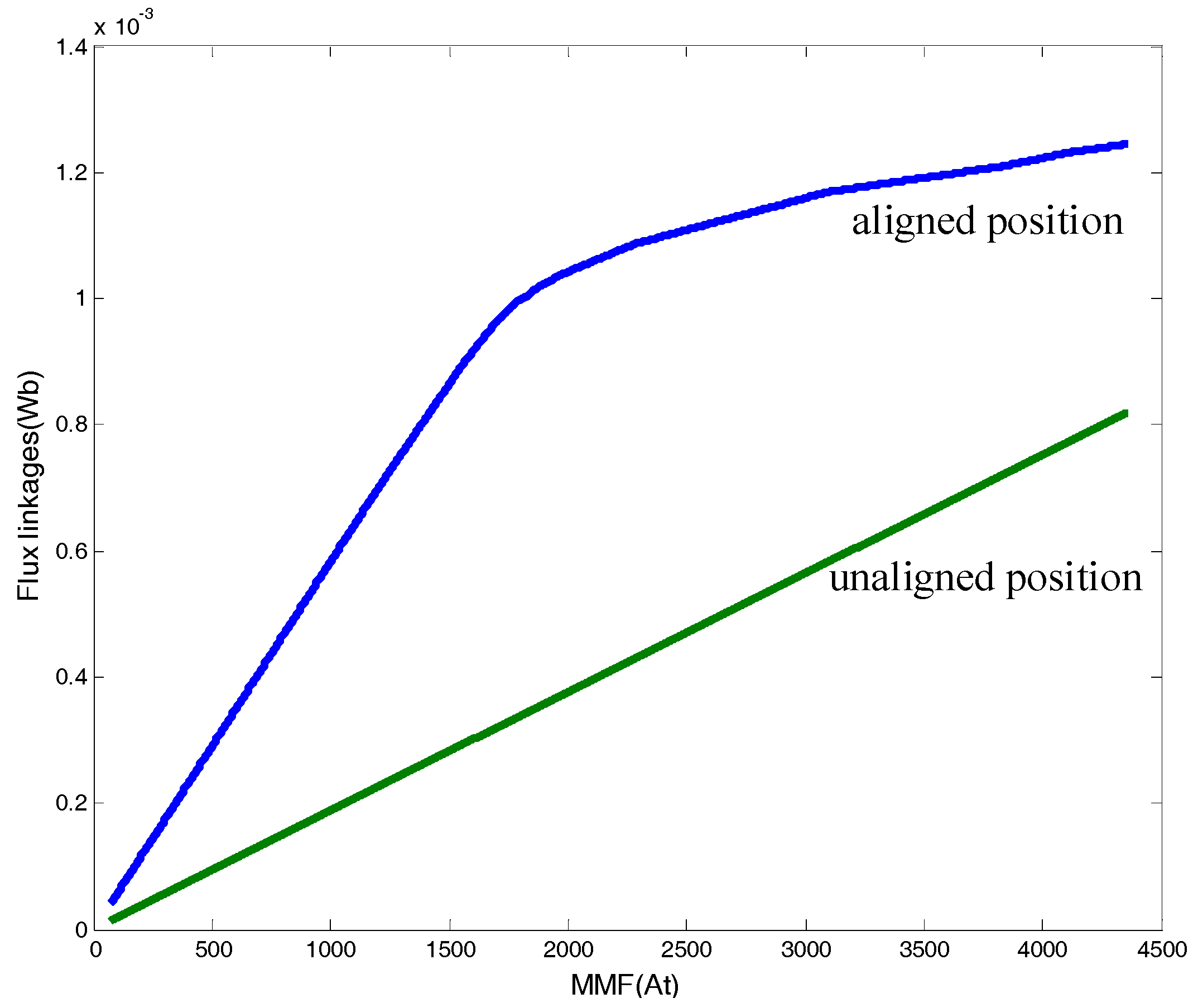
The electromagnetic torque of DSSRM is based on the inductance variation of the stator winding, which is a nonlinear function of stator current and rotor position. In this paper, the optimal operation point of MMF is defined by the maximum torque, which is a design rule for the rated current and winding turns. Through the previous magnetic circuit analysis, the flux linkages corresponding to MMF of aligned and unaligned positions are determined, as shown in Figure 17. The output power of DSSRM is calculated using the co-energy, which can be represented as the area enclosed between aligned and unaligned curves. The electric energy can be converted to torque by the variation of co-energy. Thus, the torque can be determined as:
where is co-energy; is rotor position; and is the current. The maximum torque will be occurred at the optimal MMF which is close to maximum area change ratio of the co-energy as shown in the Figure 18. Thus, the number of winding turns and rated current can be determined to fit the slot area and electrical design specification.
3. Optimal Design of DSSRM
In this paper, GA integrated into the proposed equivalent magnetic circuit of DSSRM is used to design DSSRM, such that the ratio of torque to volume of DSSRM is maximum. Due to the maximum of the torque being proportional to the maximum variation of the co-energy, the maximum variation of the co-energy is given as the objective function of GA: .
3.1. Geometric Parameters of DSSRM Optimization
In this paper, an illustrated example of a three-phase 12-Slot-8-Pole DSSRM is given (Figure 19). The corresponding notations are defined as following.
is the outer stator tooth width.
is the inner stator tooth width.
is the rotor tooth outside width.
is the rotor tooth inner width.
is the outer stator yoke width.
is the inner stator yoke width.
is the outer stator tooth height.
is the inner stator tooth height.
is the rotor tooth height.
is the outer stator diameter.
is the shaft diameter.
is the air gap length.
is the thickness of the core.
The angles ( and ) of stator and rotor poles can be determined to fit the feasible triangle technique [9] required to design DSSRM. The constraints are given as:
- (1)
- .
- (2)
- .
- (3)
- .
- (4)
- .
- (5)
- (and ) > .
- (6)
- > .
- (7)
- Winding turns of stator slot fit the optimal MMF.
For the DSSRM design (Figure 19), to simplify the design procedure, some parameters are pre-determined, which are including of the diameter of the outer stator , the diameter of motor axis , thickness of coiled silicon steel sheet , and length of the air gap . Based on the dimension of Figure 19, the related geometric equations are given as:
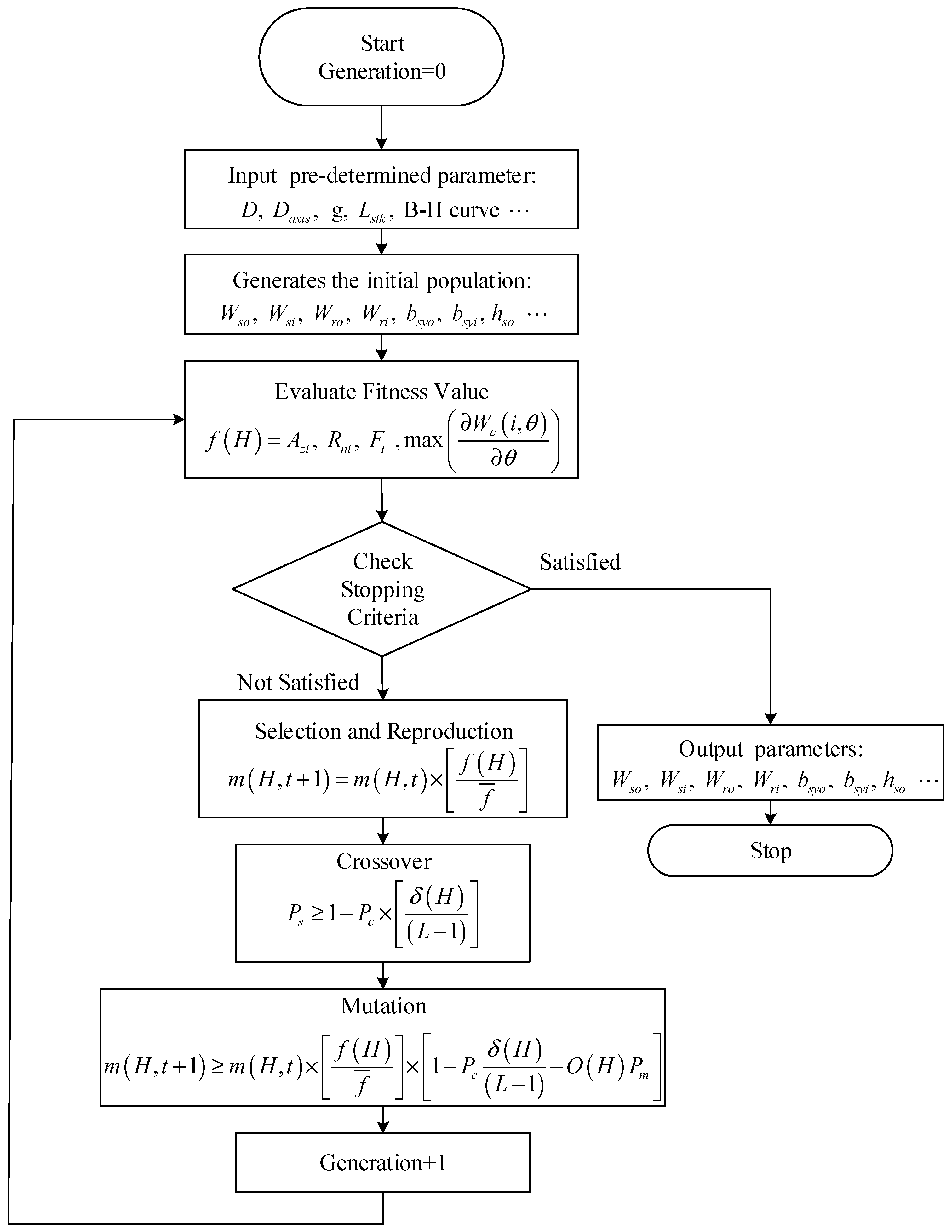
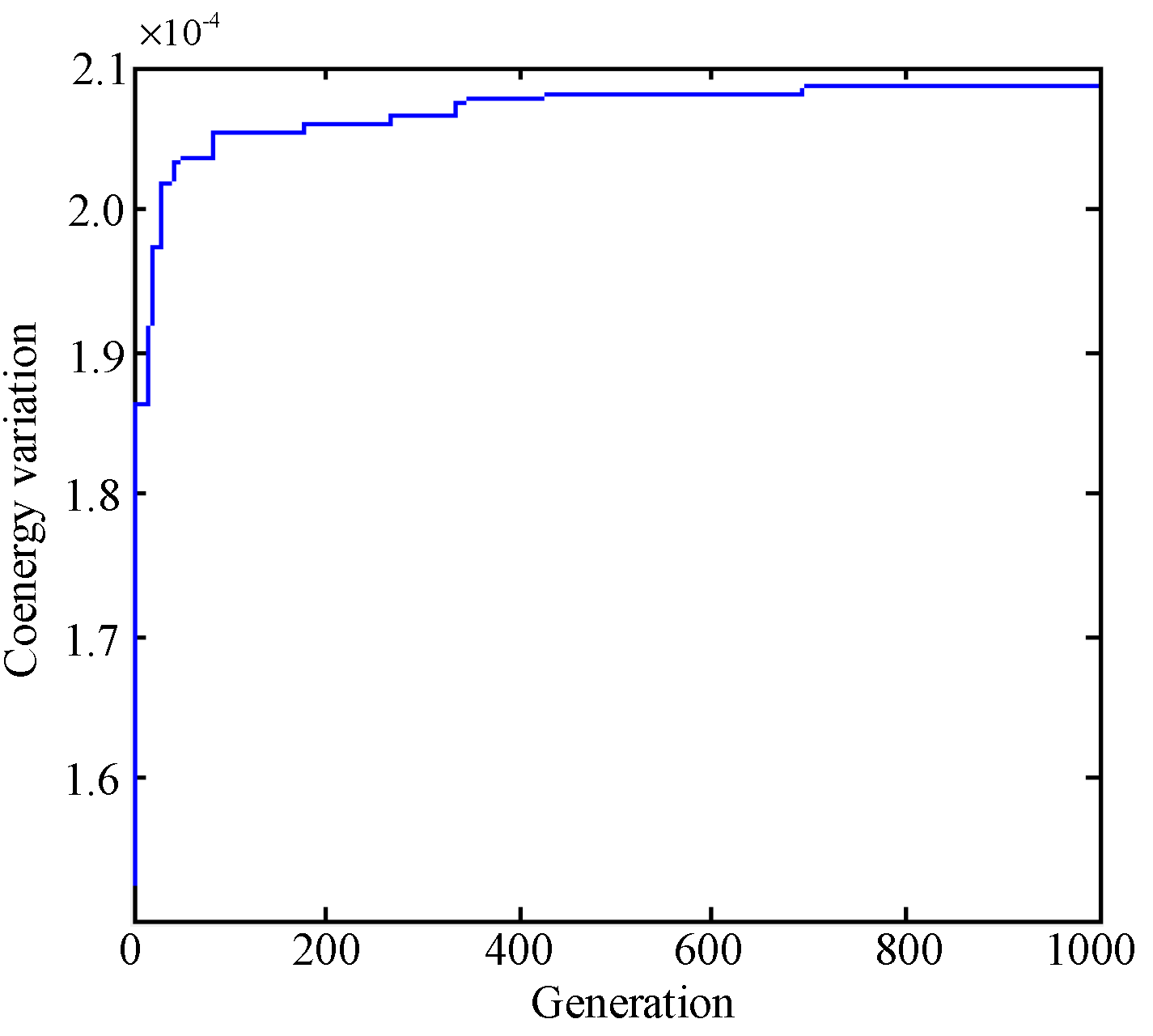
Operation procedures of GA to determine the parameters of DSSRM are constructed, which is composed of initialization, fitness value, selection and reproduction, crossover, and mutation, as shown in Figure 20. In operating procedures of GA, the initial values of DSSRM optimization are considered as input parameters. According to the constraints mentioned above, the initial population of geometric parameters can be determined. With the geometric parameters and B-H curve, the fitness value of analytical solution of equivalent magnetic circuit can be done, and used as the performance index for DSSRM optimization. Then, the population of geometric parameters is calculated via selection and reproduction, crossover, and mutation. The procedures can repeated within allowed limits until the design requirements are met. Based on the proposed design methodology, the optimal design of the proposed DSSRM can be achieved. The evolution curve is shown in Figure 21 and the calculated geometric parameters of the DSSRM are shown in Table 1.
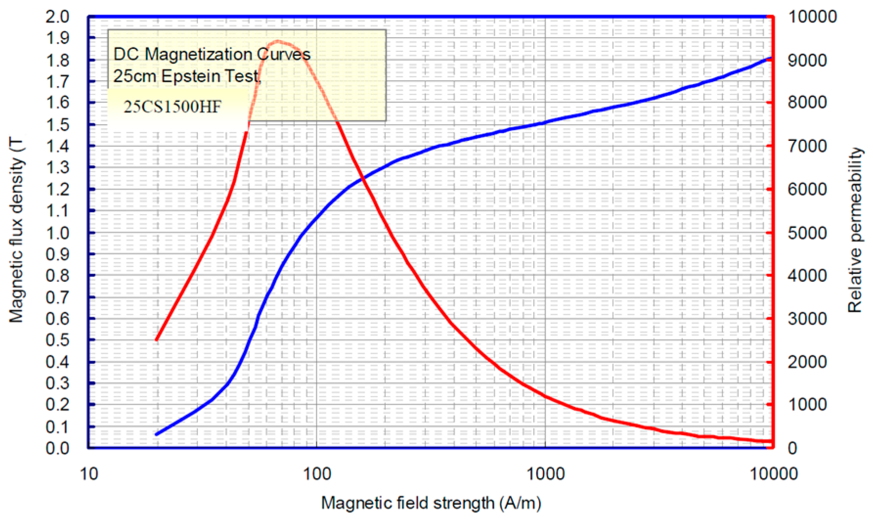
3.2. Structural Decomposition Diagram and Prototype of DSSRM
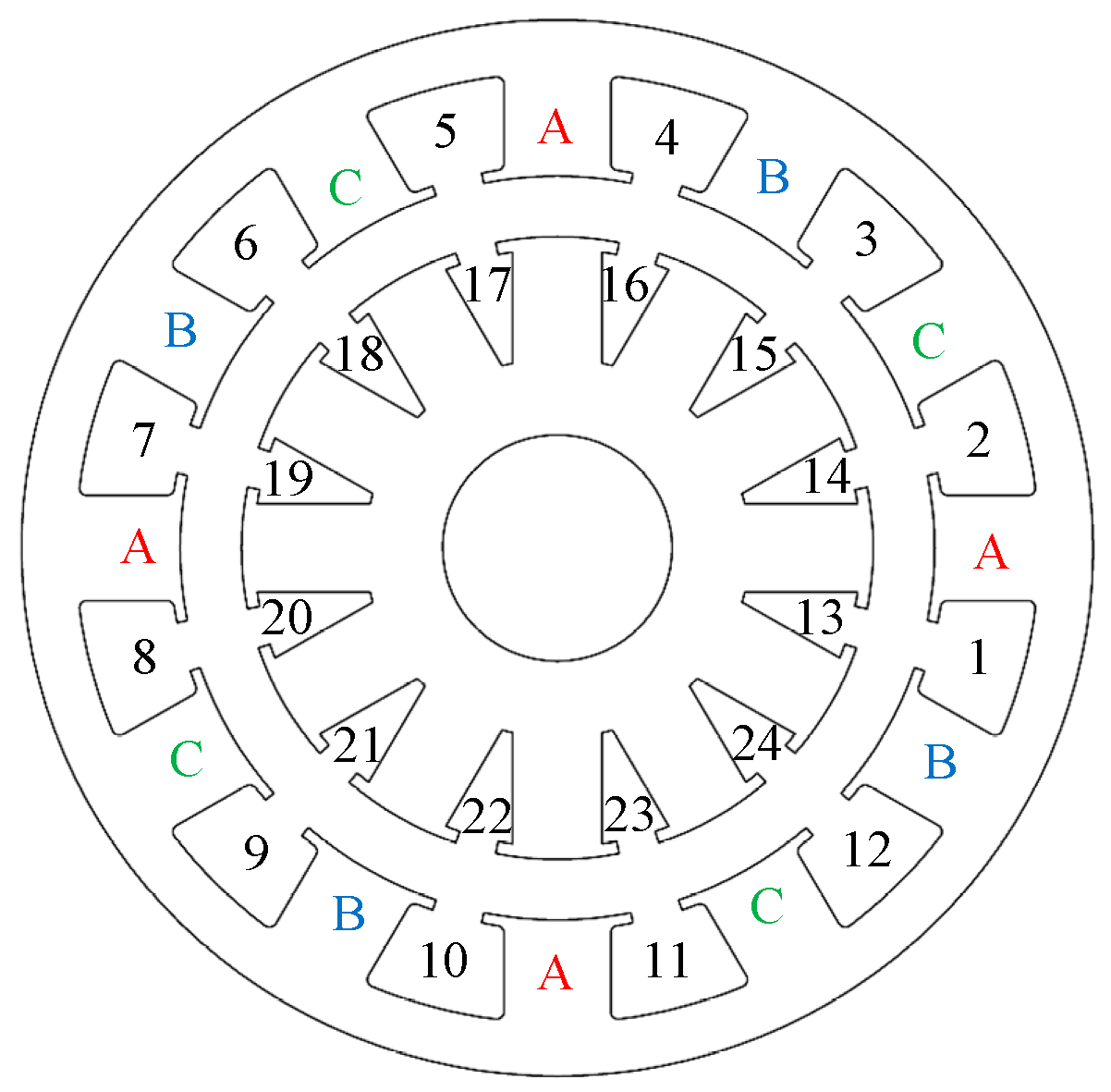
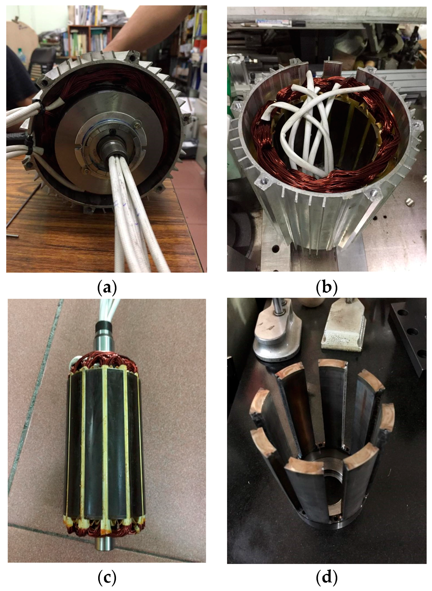
The proposed DSSRM is a three-phase 12-Slot-8-Pole and its power is 3 KW with 48 V input voltage. The steel material of the stator is 25CS1500HF made by China Steel Corporation and its B-H curve is shown in Figure 22. For the design of coil winding of the stator, 12.5 A/mm2 of the current density and 1.1 mm of wire diameter are determined. One turn with five-cord-thread concentrated winding is given and its slot fill factor can be calculated as 60%. The detail of the winding structure can be seen in Figure 23. To verify the validity of proposed DSSRM, a prototype of a 12/8 DSSRM is manufactured, as shown in Figure 24. Figure 24a shows the whole view of proposed DSSRM. The outer (Figure 24b) and inner (Figure 24c) stators have windings. The stator shaft is fixed to the inner stator the segmental rotor (Figure 24d) by nonmagnetic isolator, rotor back cover and rotor front cover. The rotor shaft is mounted on rotor front cover. The motor power output is unilateral from the rotor shaft, and the inner stator is fixed to back shell.
4. Simulation Results
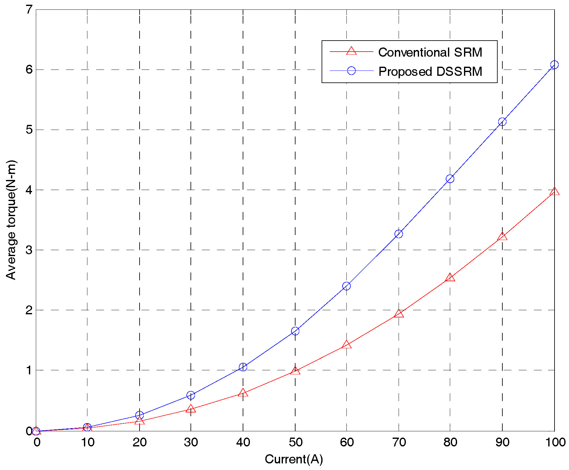
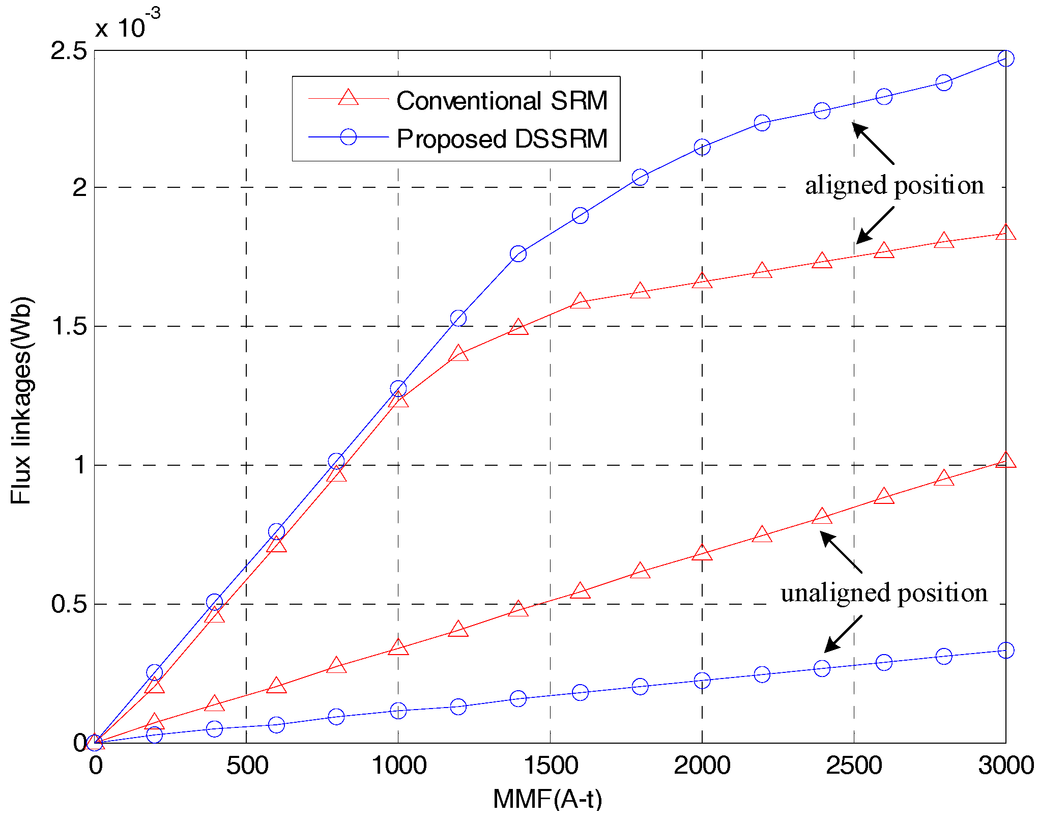
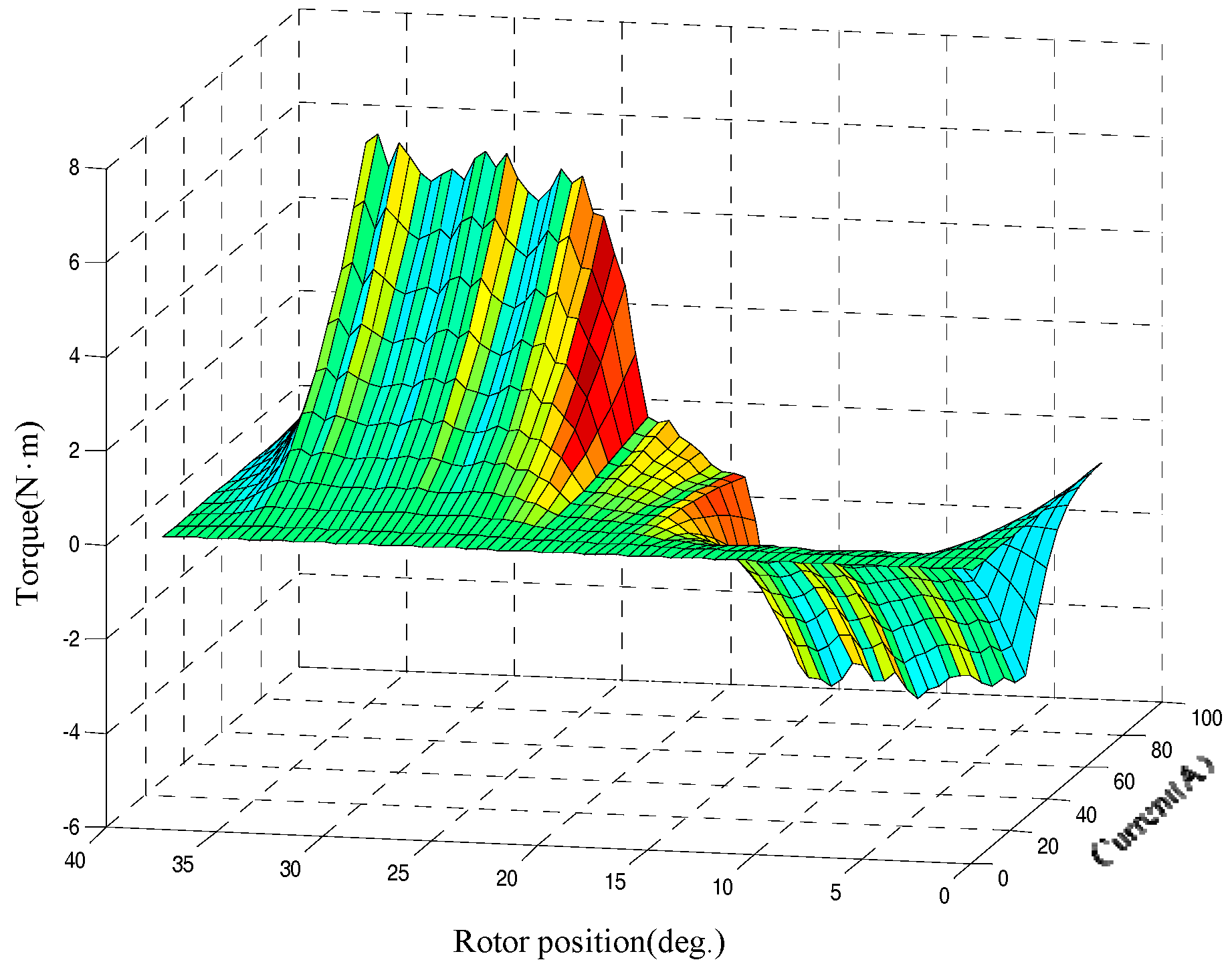
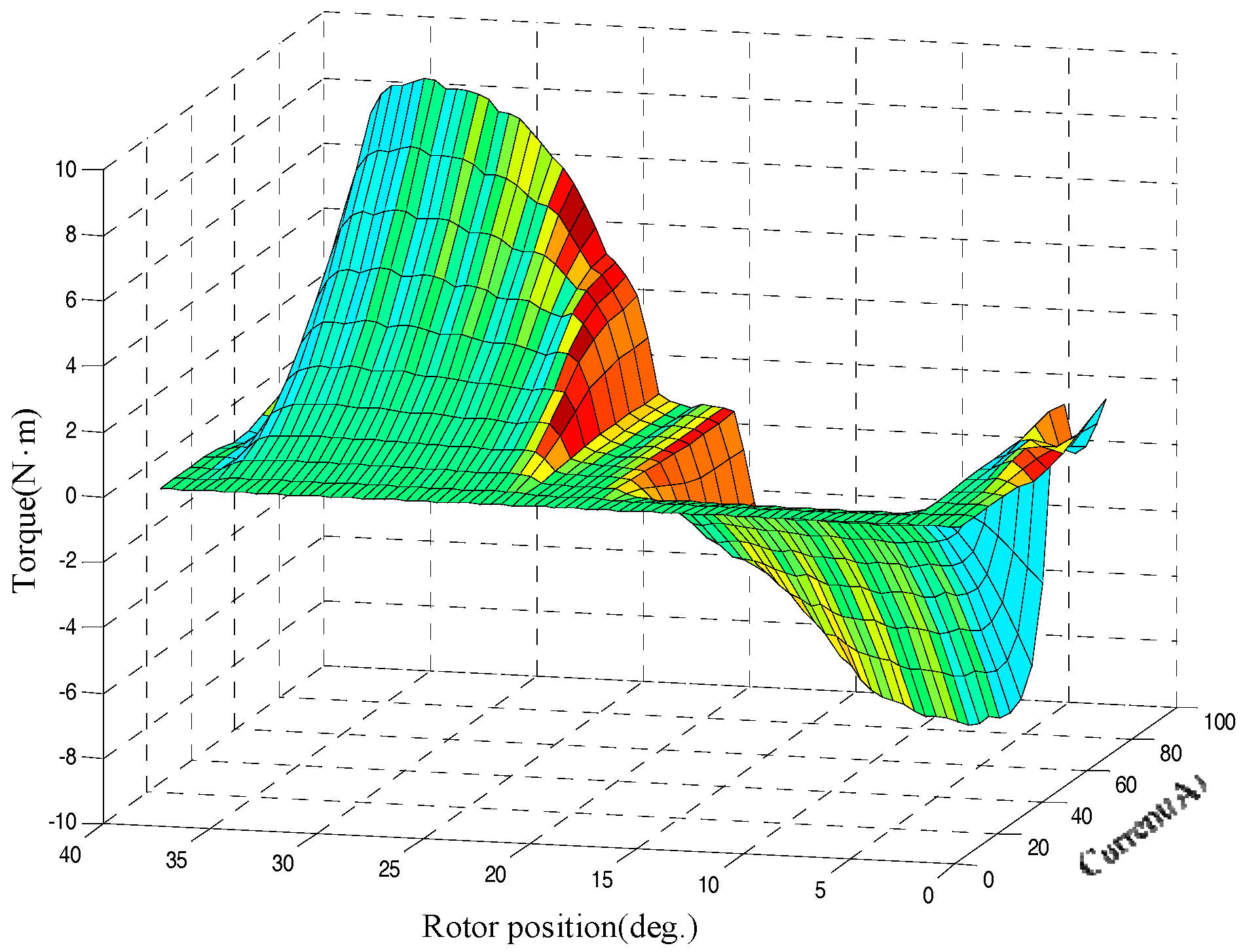
To verify the efficiency of the proposed method, a 2D FEM model is employed to analyze the characteristic of the DSSRM and to be compared with the conventional SRM. As shown in Table 2, the parameters of the conventional 12/8 SRM are determined by commercially available product. To effectively compare the torques per volume of conventional SRM and the proposed DSSRM, some dimensions of the two motors with 3 KW are given as the same in this paper, such as equivalent air gap length, diameters of stator and rotor, and length of stack, as shown in Table 2. Figure 25 shows the flux linkages corresponding to MMF of conventional SRM and designed DSSRM. For SRM or DSSRM, the difference of flux linkages between aligned and unaligned positions is proportional to MMF. At unaligned position, the minimum inductance of the proposed DSSRM is smaller than that of the SRM. At aligned position, the maximum inductance of the proposed DSSRM is larger than that of the SRM. Figure 26 and Figure 27 show the torque profiles of the conventional SRM and proposed DSSRM, respectively. Figure 28 shows the average torques of conventional SRM and proposed DSSRM. The average torque generated by proposed DSSRM is larger than that of conventional SRM. Therefore, for the same torque output, less current of the proposed DSSRM is required and the electrical loads can also be reduced. It can be found that the proposed DSSRM can accommodate more conductors and reduces heat concentration of the stator.
5. Conclusions
This paper presents a mathematic modeling of DSSRM with equivalent magnetic circuit to precisely predict the magnetic flux linkages of aligned and unaligned positions. GA integration of the proposed equivalent magnetic circuit is developed for rapid optimization of DSSRM to reach the maximum of the ratio of torque to volume of DSSRM. Compared to conventional SRM, an illustrated example of a 3-KW three-phase 12-Slot-8-Pole DSSRM is used to verify the efficiency of the proposed method. Simplified 2-D electromagnetic models are analyzed and simulated. Finally, results of the analytical calculations and FEA are validated by the proposed motor to show the accuracy of the designed strategy. In fact, from the results, the torque output of the proposed DSSRM is about 1.5 times that of the conventional 12/8 SRM under the same input current.
Conflicts of Interest
The author declares no conflict of interest.
References
- Asgar, M.; Afjei, E.; Torkaman, H. A New Strategy for Design and Analysis of a Double-Stator Switched Reluctance Motor: Electromagnetics, FEM, and Experiment. IEEE Trans. Magn. 2015, 51, 8208808. [Google Scholar] [CrossRef]
- Radun, A. Analytical Calculation of the Switched Reluctance Motor’s Unaligned Inductance. IEEE Trans. Magn. 1999, 35, 4473–4481. [Google Scholar] [CrossRef]
- Isfahani, A.H.; Fahimi, B. Comparison of Mechanical Vibration between a Double-Stator Switched Reluctance Machine and a Conventional Switched Reluctance Machine. IEEE Trans. Magn. 2014, 50, 7007104. [Google Scholar] [CrossRef]
- Arbab, N.; Wang, W.; Lin, C.; Hearron, J.; Fahimi, B. Thermal Modeling and Analysis of a Double-Stator Switched Reluctance Motor. IEEE Trans. Energy Convers. 2015, 30, 1209–1217. [Google Scholar] [CrossRef]
- Abbasian, M.; Moallem, M.; Fahimi, B. Double-Stator Switched Reluctance Machines (DSSRM): Fundamentals and Magnetic Force Analysis. IEEE Trans. Energy Convers. 2010, 25, 589–597. [Google Scholar] [CrossRef]
- Abbasian, M.; Hanaeinejad, V. Torque Optimization of Double-Stator Switched Reluctance Machine. Appl. Mech. Mater. 2013, 313–314, 45–50. [Google Scholar] [CrossRef]
- Tavakkoli, M.; Moallem, M. Optimum Rotor Shaping for Torque Improvement of Double Stator Switched Reluctance Motor. J. Electr. Eng. Technol. 2014, 9, 1315–1323. [Google Scholar] [CrossRef]
- Huang, Y.; Zhou, T.; Dong, J.; Lin, H.; Yang, H.; Cheng, M. Magnetic Equivalent Circuit Modeling of Yokeless Axial Flux Permanent Magnet Machine with Segmented Armature. IEEE Trans. Magn. 2014, 50, 8104204. [Google Scholar] [CrossRef]
- Liptak, M. Principle of Design of Four-Phase Low-Power Switched Reluctance Machine Aimed to the Maximum Torque Production. J. Electr. Eng. 2004, 55, 138–143. [Google Scholar]
Figure 1.
Profiles of: (a) switched reluctance motor; and (b) double-stators switched reluctance motor.
Figure 1.
Profiles of: (a) switched reluctance motor; and (b) double-stators switched reluctance motor.
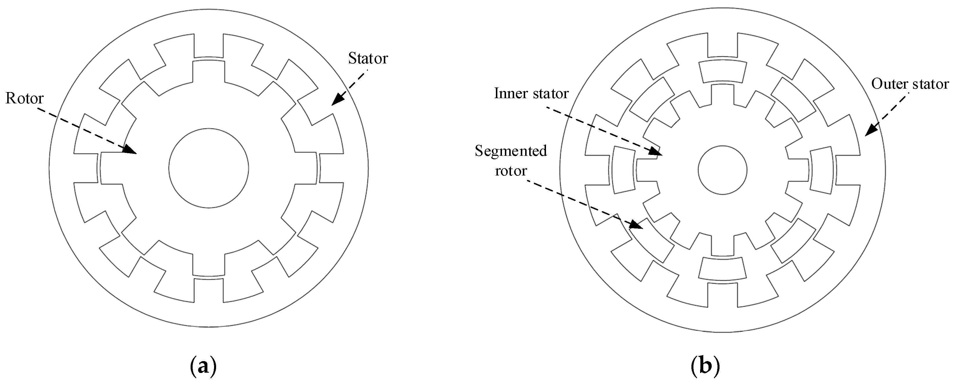
Figure 2.
Magnetic flux of the single phase of DSSRM to align with the excited stator pole.
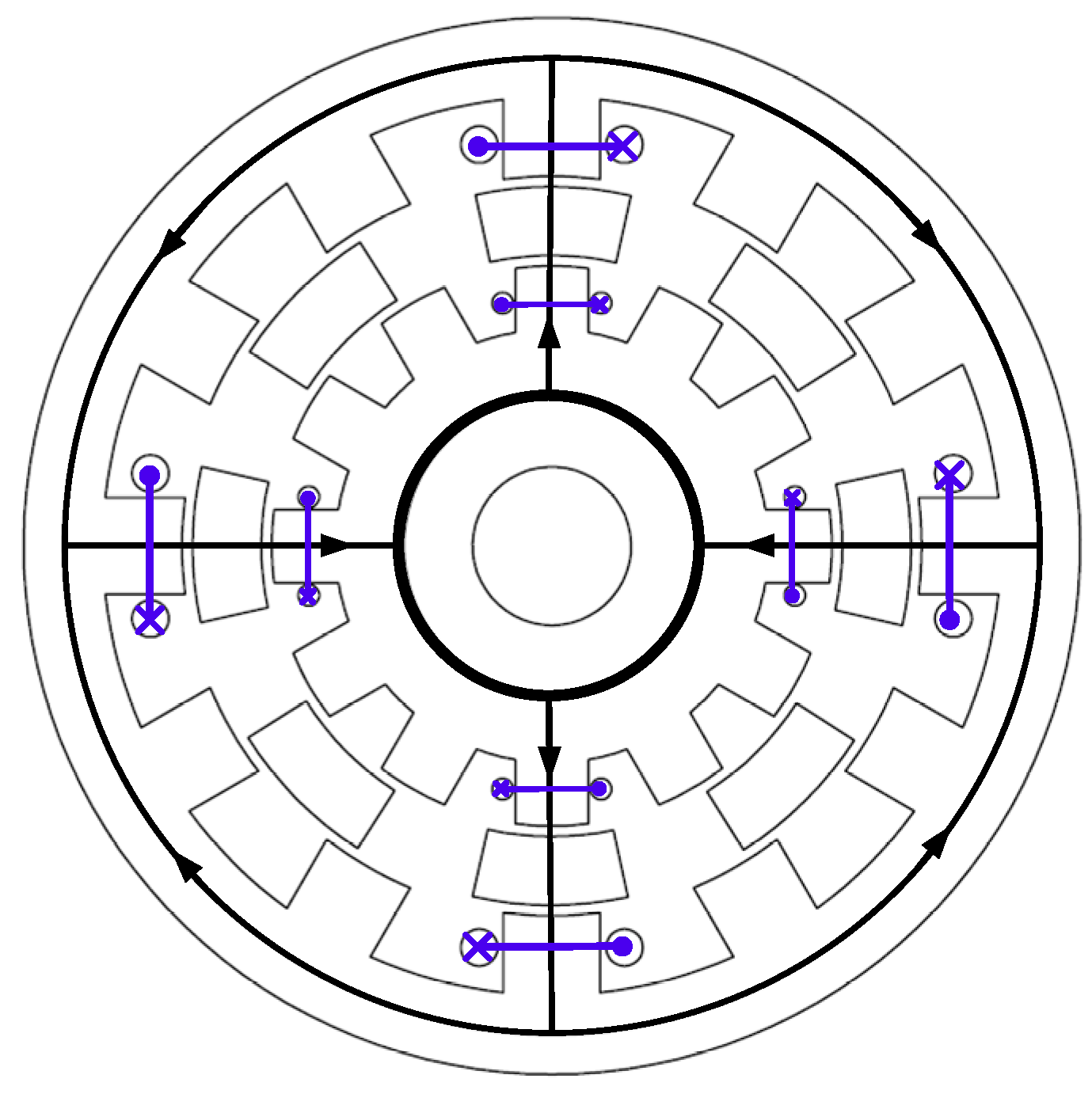
Figure 3.
Equivalent magnetic circuit of Figure 2.
Figure 3.
Equivalent magnetic circuit of Figure 2.
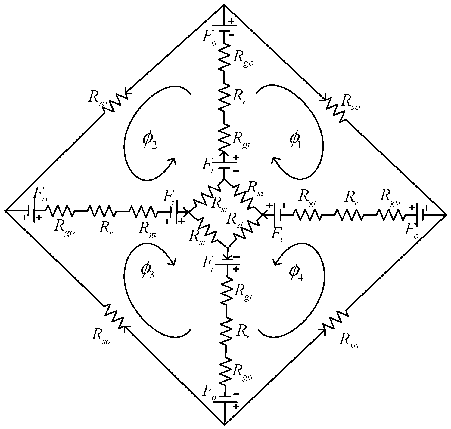
Figure 4.
Permeance distribution for the rotor to align its poles with the excited stator poles.

Figure 5.
Magnetic circuit with single excited phase.

Figure 6.
Comparison of flux linkage at aligned position between analytical solution and numerical solution of finite-element method (FEM).
Figure 6.
Comparison of flux linkage at aligned position between analytical solution and numerical solution of finite-element method (FEM).

Figure 7.
Magnetic flux of the single phase of DSSRM to unaligned with the excited stator pole.

Figure 8.
Permeances between stator and rotor at completely unaligned position.

Figure 9.
Boundary condition of the magnetic field intensity of the rotor slots.
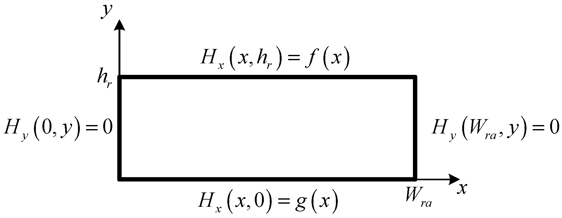
Figure 10.
Boundary condition of the magnetic field intensity of the outer stator.
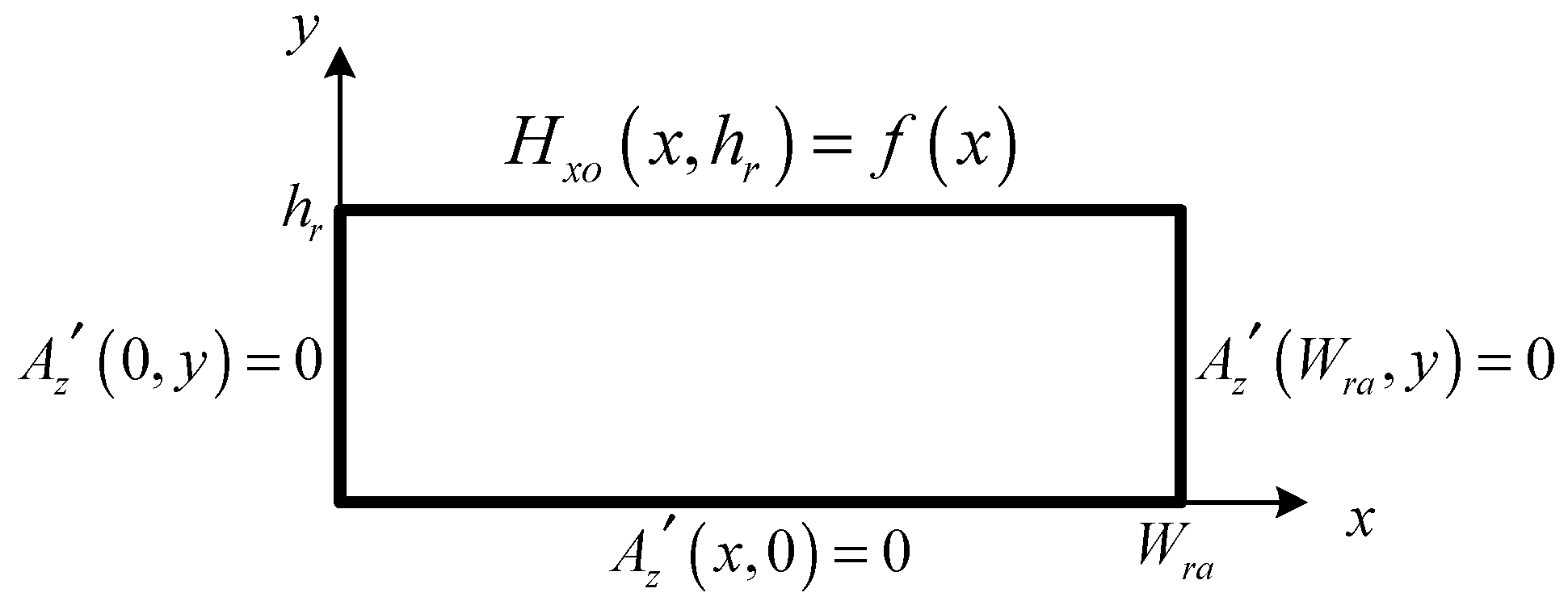
Figure 11.
Expression of magnetic field intensity .

Figure 12.
Boundary condition of the magnetic field intensity of the inner stator.

Figure 13.
Expression of magnetic field intensity .

Figure 14.
Equivalent magnetic circuit of completely unaligned position between stator and rotor in Figure 8.
Figure 14.
Equivalent magnetic circuit of completely unaligned position between stator and rotor in Figure 8.

Figure 15.
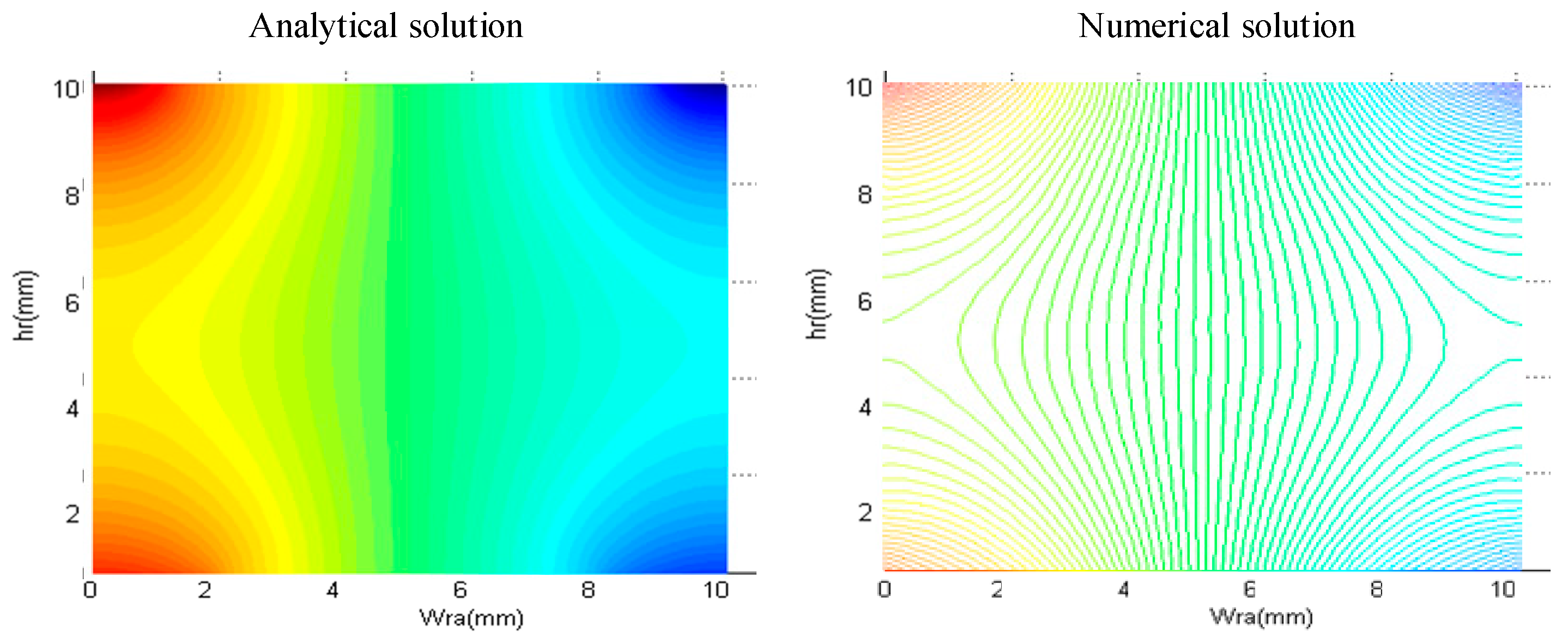
Comparison of the 2D total magnetic potential vector between analytical solution and numerical solution from FEM.
Figure 15.
Comparison of the 2D total magnetic potential vector between analytical solution and numerical solution from FEM.

Figure 16.
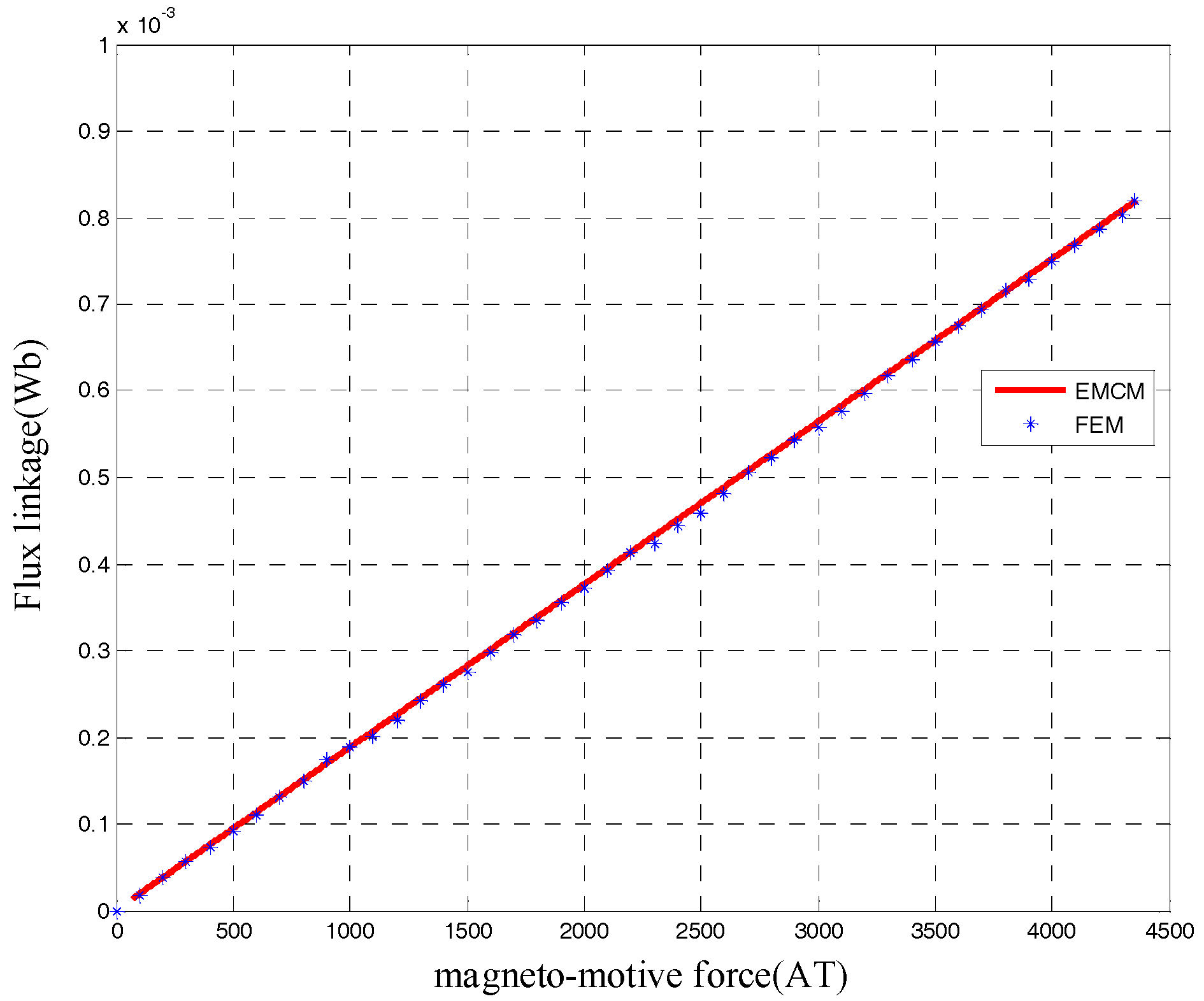
Comparison of flux linkages at completely unaligned position between analytical solution and numerical solution from FEM.
Figure 16.
Comparison of flux linkages at completely unaligned position between analytical solution and numerical solution from FEM.

Figure 17.
Flux linkages corresponding to MMF of aligned and unaligned positions.

Figure 18.
Plot of the variation of the co-energy corresponding to MMF.
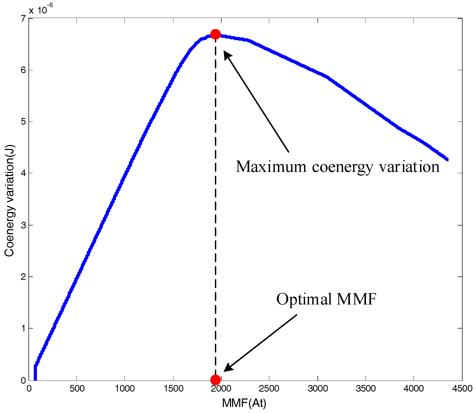
Figure 19.
Dimension diagram of the proposed DSSRM.

Figure 20.
Operation procedures of Genetic algorithm for double-stators switched reluctance motor.

Figure 21.
Evolution curve of the designed DSSRM.

Figure 22.
B-H curve of steel material.

Figure 23.
Distribution of phases and slot numbers of 12/8 DSSRM.

Figure 24.
Prototype of Proposed DSSRM: (a) whole view; (b) outer stator; (c) inner stator; and (d) rotor.
Figure 24.
Prototype of Proposed DSSRM: (a) whole view; (b) outer stator; (c) inner stator; and (d) rotor.

Figure 25.
Flux linkages of conventional SRM and proposed DSSRM at aligned and unaligned positions.

Figure 26.
Torque profile of conventional SRM.

Figure 27.
Torque profile of proposed DSSRM.

Figure 28.
Average torque for conventional SRM and proposed DSSRM.

Table 1.
Optimal geometric parameters of the DSSRM (unit: mm).
| Symbol | Quantity | |
|---|---|---|
| outer stator tooth width | 14.01 | |
| inner stator tooth width | 11.79 | |
| Rotor tooth outside width | 25.99 | |
| Rotor tooth inner width | 22.06 | |
| Outer stator yoke width | 7.56 | |
| Inner stator yoke width | 9.87 | |
| Outer stator tooth height | 9.91 | |
| Inner stator tooth height | 19.34 | |
| Rotor tooth height | 7.92 | |
| Outer stator diameter | 140 | |
| Shaft diameter | 30 | |
| Air gap length | 0.2 | |
| Thickness of the core | 130 | |
| The total number of turns per slot | 20 |
Table 2.
Parameters of conventional SRM and proposed DSSRM.
| Parameters | Conventional | Proposed |
|---|---|---|
| 12/8 SRM | 12/8 DSSRM | |
| Number of phases | 3 | 3 |
| Outer radius of outer stator (mm) | 140 | 140 |
| Length of air gap (mm) | 0.4 | 0.2 2 |
| Outer radius of rotor (mm) | 104.66 | 104.66 |
| Length of stack (mm) | 130 | 130 |
| Rotor inertia () | 4.39 × 10⁻² | 1.97 × 10⁻² |
| Number of turns/phases (N) | 14 | 20 |
| Wire diameter (mm) | 1.1 5 | 1.1 5 |
© 2017 by the author. Licensee MDPI, Basel, Switzerland. This article is an open access article distributed under the terms and conditions of the Creative Commons Attribution (CC BY) license (http://creativecommons.org/licenses/by/4.0/).
Share and Cite
MDPI and ACS Style
Yao, W.-S. Rapid Optimization of Double-Stators Switched Reluctance Motor with Equivalent Magnetic Circuit. Energies 2017, 10, 1603. https://doi.org/10.3390/en10101603
AMA Style
Yao W-S. Rapid Optimization of Double-Stators Switched Reluctance Motor with Equivalent Magnetic Circuit. Energies. 2017; 10(10):1603. https://doi.org/10.3390/en10101603
Chicago/Turabian StyleYao, Wu-Sung. 2017. "Rapid Optimization of Double-Stators Switched Reluctance Motor with Equivalent Magnetic Circuit" Energies 10, no. 10: 1603. https://doi.org/10.3390/en10101603
Note that from the first issue of 2016, this journal uses article numbers instead of page numbers. See further details here.