Flexible Compensation of Voltage and Current Unbalance and Harmonics in Microgrids
by
 and
and
Seyyed Yousef Mousazadeh Mousavi
1, 
Alireza Jalilian
1,2,*,
Mehdi Savaghebi
3 and
Josep M. Guerrero
3
1
Department of Electrical Engineering, Iran University of Science and Technology, Tehran 16846-13114, Iran
2
Center of Excellence for Power System Automation and Operation, Iran University of Science and Technology, Tehran 16846-13114, Iran
3
Department of Energy Technology, Aalborg University, Aalborg 9220, Denmark
*
Author to whom correspondence should be addressed.
Energies 2017, 10(10), 1568; https://doi.org/10.3390/en10101568
Submission received: 13 August 2017
/
Revised: 25 September 2017
/
Accepted: 27 September 2017
/
Published: 11 October 2017
Abstract
:In recent years, the harmonics and unbalance problems endanger the voltage and current quality of power systems, due to increasing usage of nonlinear and unbalanced loads. Use of Distributed Generation (DG)-interfacing inverters is proposed for voltage or current compensation. In this paper, a flexible control method is proposed to compensate voltage and current unbalance and harmonics using the distributed generation (DG)-interfacing inverters. This method is applicable to both grid-connected and islanded Microgrids (MGs). In the proposed method, not only the proper control of active and reactive powers can be achieved, but also there is flexibility in compensating the voltage or current quality problems at DG terminals or Points of Common Coupling (PCCs). This control strategy consists of active and reactive power controllers and a voltage/current quality-improvement block. The controller is designed in a stationary (αβ) frame. An extensive simulation study has been performed and the results demonstrate the effectiveness of the proposed control scheme. Depending on the compensation modes, the harmonics and unbalance compensation of DG output current, MG-injected current to the grid, as well as PCC and DG voltages, can be achieved in grid-connected operation of MG while in the islanded operation, and the PCC and DG voltages compensation can be obtained through the proposed control scheme.
1. Introduction
In recent years, due to the disadvantages of conventional fossil fuels such as air pollution and extinction, the concept of benefitting from renewable energy sources (RESs) has attracted more attention [1,2,3]. Microgrid (MG) and Distributed Generation DG concepts have emerged for better use of the RESs and enhancing efficiency, power quality and reliability of the conventional power systems [4,5]. Since the output voltage of many of the RESs are unregulated DC or variable/high frequency AC, the integration of renewable energy to the utility grids or MGs requires power electronic converters, with an inverter as the last conversion stage in case of AC systems [6]. These inverters are usually connected to the grid by an LCL or LC filter [7,8].
On the other hand, in the presence of unbalanced, single-phase and nonlinear loads, excessive voltage unbalance and harmonics may appear in the MGs. The unbalanced and harmonic distorted voltage leads to more losses and less stability of the MG. It also causes malfunction of power electronics converters and induction motors [9]. Due to these problems, the allowed limit for voltage unbalance recommended by the International Electrotechnical Commission (IEC) is 2%, while the recommended limit for voltage total harmonic distortion (THD) is 5% [10].
Incorporation of multifunctional interfacing inverters for compensation of power quality-related problems has been proposed recently in some research works, such as [11,12,13,14,15,16]. With proper control of these inverters, not only the extracted energy of RESs can be injected into the grid or MG, but also the improvement of voltage and current quality may be achieved. In [17], droop control for injecting the negative sequence voltage is proposed. A method based on injecting negative sequence voltage is presented in [9]. The voltage injection is based on negative sequence reactive power to share the compensation effort between DG units. The voltage quality improvement using secondary and tertiary control is also proposed in [18,19,20,21]. The compensation of unbalanced and nonlinear loads in a multi-bus islanded MG, using an adjustable resonance frequency, a droop control strategy, and a negative and harmonic sequence impedance controller, is discussed in [22].
All of the aforementioned works have been focused on only voltage or current quality improvement. In [23], a flexible voltage and current harmonic compensation approach is proposed through DG-interfacing inverters in a single-phase MG. The performance of the method is improved by using a frequency adaptive controller which is presented in [24]. In this paper, extension of control methods of [23,24] is proposed in three-phase MGs to enable unbalance and harmonic compensations. In the proposed method, four harmonic and unbalance compensation modes can be achieved, while the fundamental positive sequence components of DG output voltage can also be properly controlled. The main contributions of this paper can be highlighted as follows:
- Simultaneous control of fundamental positive and negative sequences, as well as harmonic components of voltage and current, is achieved for three-phase DG-interfacing inverters.
- A flexible voltage or current compensation of nonlinear and unbalanced loads is proposed.
- The proposed method is applicable in both grid-connected and islanded modes of three-phase MGs.
- Four unbalanced and harmonic voltage or current compensation strategies can be achieved using this method.
The extensive simulation which is implemented in MATLAB/Simulink (2016a Version, MathWorks, Natick, MA, USA) verifies the effectiveness of the power-quality improvement method in both grid-connected and islanded operation modes of an MG.
2. Control Approach for DG-Interface Inverter
2.1. Power Control and Virtual Impedance
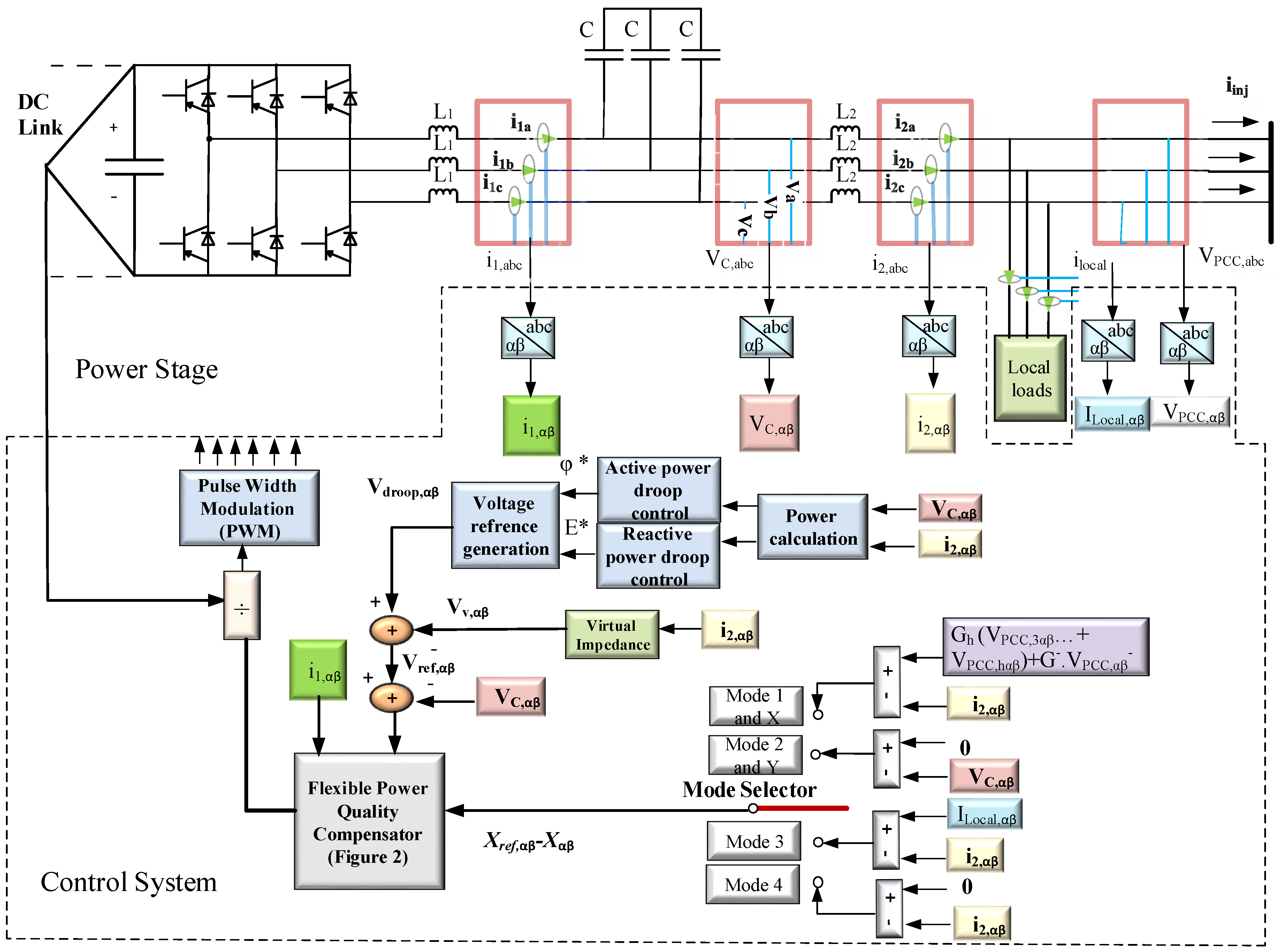
Figure 1 shows the power stage and control system of the DG-interfacing inverter. As shown in this figure, the power stage consists of a DC link, a three-phase inverter and an LCL filter. In the control system, the positive sequence active and reactive powers are calculated based on instantaneous active and reactive power theory [25].
In the control system, the droop-based voltage (Vdroop,αβ) is generated by droop controllers. Virtual impedance is used for decoupling the reactive and active powers droop controllers and enhancing the dynamics of the system [26,27]. Four voltage or current unbalance and harmonic compensation modes can be selected by the “Mode Selector” switch. Since the control system is based on the αβ frame, the three-phase voltages and currents should be transferred to the αβ reference frame using Clark’s transformation [9].
It should be mentioned that, since the present work is focused on three-phase three-wire MGs, the zero sequence component of voltage and current are not taken into account [9,28,29].
If a three-phase inverter is connected to a mainly inductive grid, the injected positive sequence (PS) active and reactive powers are related to the angle between output voltage of DG and grid (φ) and voltage amplitude (E), respectively; hence, P-φ and Q-E power droops are applied in order to generate reference voltage in this paper. These power droops, which add virtual inertia to the power electronics inverters, are written as [30]:
where φ0 and φ* represent the rated and voltage-phase angle reference, respectively. P+ and Q+ are the fundamental positive sequence active and reactive powers, respectively. E0 and E* are rated and reference values of voltage amplitude, respectively. mP and mI are PS active power proportional and integral coefficients, respectively, while nP and nI represent the integral and proportional coefficients related to reactive power, respectively. P* and Q* are reference active and reactive powers, respectively. P*, Q* and nI must be zero if the MG operates in islanded mode [23].
As was mentioned before, the P-φ and Q-E droops are designed with the assumption that the MG is mainly inductive. For compensating the effect of the resistance and decoupling of the P-ϕ and Q-E droops, inductive virtual impedance is used. The fundamental frequency virtual impedance is expressed in (2) and (3) [27]:
where Rv and Lv represent the virtual resistance and inductive impedances, respectively. The reference voltage will be written by (4):
2.2. Proposed Flexible Controller for Unbalance and Harmonic Compensation
As shown in Figure 1, four power-quality improvement strategies can be obtained by the “Mode Selector” switch. Based on this, the following compensation modes are taken into account (the mode’s number associates with the position of “Mode Selector” switch):
- Mode 1—unbalance and harmonic compensation of Point of Common Coupling (PCC) voltage (VPCC): in this mode, the unbalance and harmonic voltage compensation is achieved by using the following equation as input of flexible power quality controller (FPQC):
where G− and Gh represent negative sequence and harmonic virtual conductance, respectively. The extraction of the fundamental negative sequence and harmonic (FNS&H) components of VPCC is performed using the Second Order Generalized Integrator (SOGI) method, which is presented in [29]. The multifunctional inverter acts as damping resistance at FNS&H components, and low-impedance paths are created for respective current components; hence, the voltage quality will be enhanced. This compensation is useful when a sensitive load is connected in PCC. It should be mentioned that in this mode, the inverter acts in current controlled mode (CCM) for FNS&H components.
- Mode 2—unbalance and harmonic compensation of DG output voltage (VC): The capacitor voltage will be balanced if the (0-VC,αβ) is applied as the input of FPQC. The unbalance and harmonic compensation of VC is obtained by injecting FNS&H sequences of VC; hence, the performance of the inverter acts in voltage controlled mode (VCM) in FNS&H sequences. The compensation is important when a sensitive load is connected near the DG. The selection of Modes 1 or 2 is dependent on the location of the sensitive load.
- Mode 3—local unbalanced and nonlinear loads compensation: in this mode, the aim of the compensation is the unbalance and harmonic compensations of MG-injected current (Iinj). Using (Ilcaoal-I2) as input of FPQC, the multifunctional inverter acts as an active filter in negative and harmonic sequences, therefore, the FNS&H parts of unbalanced and nonlinear loads are supplied by the DG-interfacing inverter and Iinj will be balanced. The mode can be activated when there is a limitation for the unbalance and harmonics current of an MG, since each system has limitations in harmonic and unbalance injections according to IEEE 519 and EN 50160 standards.
- Mode 4—the output current compensation of DG unit (I2): in this mode, which is called the unbalance and harmonics rejection mode, the output current of DG will be compensated. This mode is important when the DG delivers maximum power to the grid, and injection of unbalance and harmonics current can increase the current of one/two phase(s) higher than the rated one.
Figure 2 shows more details of the proposed control diagram. As can be observed in this figure, the control scheme consists of three parts. The first part is related to the PS voltage control, where Vref is tracked as a VCM inverter. The second part is related to unbalance and harmonic compensation, and acts as a CCM inverter except in Mode 2. As discussed before, since the compensation of VC is achieved by injecting negative and harmonic sequence voltage, the inverter acts as VCM inverter in FNS&H sequences in Mode 2. The third part is applied to provide some damping [31]. The following equation expresses these three parallel controllers:
For negative sequence and harmonic compensation, the power quality controller (PQC) can be expressed by the following equation:
where Xref and X, which are selected by “Mode Selector” switch, can be the reference and actual values of I2 or VC, respectively. KP, KUCC and KI,h represent the proportional coefficient of the resonant controller, and the unbalance and harmonics resonant coefficients of the controller, respectively. Since a low value of KP is chosen [23], all the components, including fundamental positive and FNS&H components, are decoupled.
In order to damp the resonance of the LCL filter, active and passive damping is utilized. The current of the capacitor or inverter side inductor is usually used for active damping [32,33]. In this paper, the inductor current feedback and a proportional controller (KD) are employed as the third and damping part of the flexible controller.
3. Control System Design
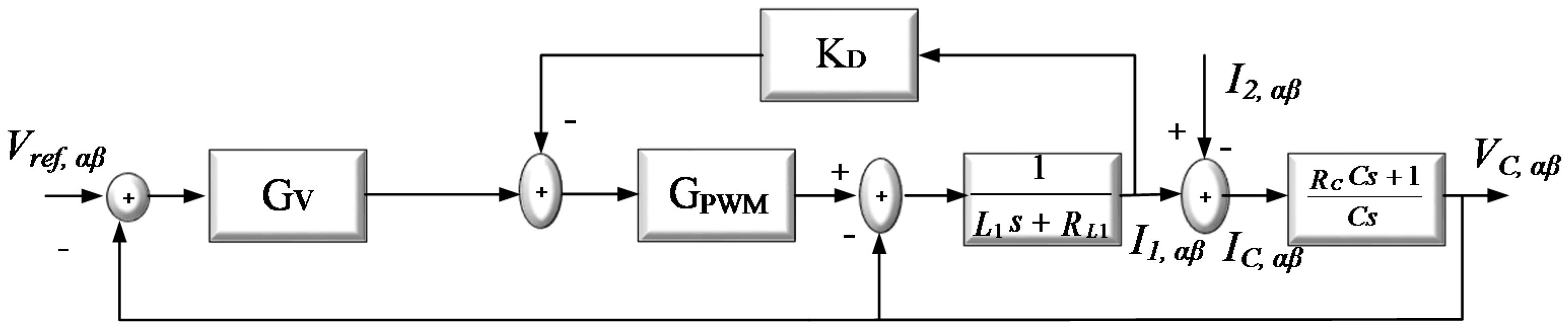
As discussed before, the control of the inverter is a flexible current-and-voltage-control method. The positive sequence of the VC is related to the first part of FPQC, and the inverter can be modeled as a VCM inverter. Figure 3 shows the positive sequence voltage generation block. Since negative and harmonic sequences are generated by PQC, this part is eliminated in PS analysis. On the other hand, since the DG-interfacing inverter acts as a CCM inverter in Modes 1, 3 and 4, only PQC and the damping controller can have an influence on the negative and harmonic sequences of DG output current; hence, the control system of the FNS&H current is merely considered as depicted in Figure 4. In these figures, the LCL filter inverter-side inductance and its resistance are represented by L1 and RL1, respectively, while L2 and RL2 are the grid-side inductance and its resistance, respectively. The capacitor of the LCL filter and its series resistance are shown by C and RC, respectively.
In other words, the inverter can be modeled using Norton- and Thevenin-equivalent circuits for FNS&H and positive sequences of fundamental frequency, respectively. As discussed before, in Mode 2 of compensation, the inverter acts as a VCM inverter in negative and harmonic sequences, and its relative model is similar to the PS part depicted in Figure 3.
The closed-loop transfer function of positive sequence capacitor voltage (GPSCV(s)) is written by the following equation, according to Figure 3:
where ZL1 = L1 s + RL1 is the impedance of the inverter-side inductance of the LCL filter and its series resistance. ZL2 = L1 s + RL1 represents the grid-side inductance and its series resistance, while ZC(s) = 1/Cs + RC is the capacitor impedance and its series resistance. GV is the transfer function of the resonance controller, which is defined according to (9), and KD is the damping gain, which is shown in Figure 2a.
According to Figure 4, the closed-loop current-transfer function of DG output FNS&H current (GONHC(s)) is written as:
where GPQC represents the power quality compensation controller, which is expressed by Equation (10). Using Equations (11) and (12), the parameters of the controllers can be determined. The cut-off bandwidth of the non-ideal resonant controllers (ωb) is recommended to be in the range of 5–15 rad/s [31]. In this paper, ωb = 5 is chosen.
Firstly, the design of the damping part of the controller will be discussed. The Bode diagram of GPSCV(s) is depicted in Figure 5 using the LCL filter parameters in Table 1, KV = 700 and ωb = 5 rad/s. The Bode diagram is depicted for three amounts of KD = 0, 20 and 100. As shown in this figure, there is a peak in resonance frequency of the LCL filter when KD = 0. The resonance is damped when KD is set at 20 and 100. The large amount of KD may cause additional resonance in the system [34]; thus, KD = 20 is the selected option.
In the FNS&H compensation controller, the proportional controller is used for better tracking of the FNS&H voltage or current, and a low value of it is adequate for the controller [31], hence, KP = 4 is chosen. The Bode diagram of the GONHC is shown in Figure 6, considering KUCC = 700, KI,3 = 500, KI,5 = 300 and KI,7 = 300. As depicted in this figure, the Bode diagram of the closed-loop transfer function is zero in the fundamental frequency for negative sequence and third-, fifth- and seventh-order harmonics; hence, the current can track its reference value.
4. Simulation Results
In this section, the effectiveness of the proposed control method for both grid-connected and islanded MG operation modes is evaluated.
To quantify the voltage and current compensation, the voltage/current unbalance factors (VUF and CUF, respectively) and individual harmonic factors with the following definitions are considered:
where / and / are Root Mean Square (RMS) values of negative and positive sequences of voltage/current, respectively. and represent the harmonic positive and negative sequences and fundamental components of voltage/current variables, respectively.
4.1. Grid-Connected Operation
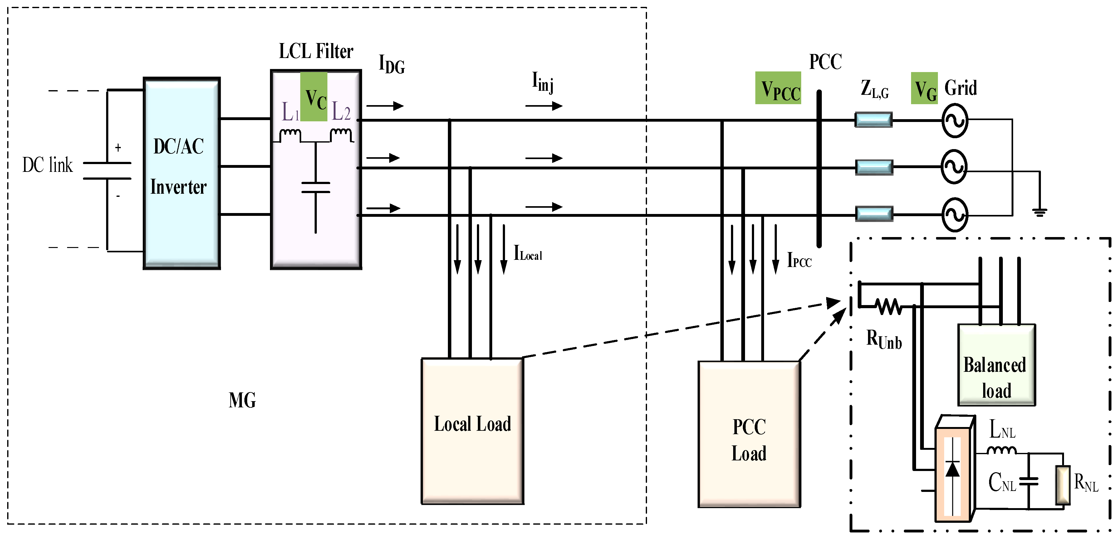
Figure 7 shows a grid-connected MG, which consists of both local and PCC-connected balanced and unbalanced linear and nonlinear loads. The linear unbalanced (single-phase) load is presented in this figure by Runb. The MG is connected to the grid through the line impedance ZL,G = R + jωL. It is assumed that the grid voltage is unbalanced with VUF = 4.5%. Control system and power stage parameters are listed in Table 1. The following five steps are used for evaluating the controller in unbalance and harmonic compensation.
- Step 1 (0 s ≤ t < 3.5 s): activation of Mode 1 for VPCC compensation.
- Step 2 (3.5 s ≤ t < 6.5 s): activation of Mode 2 for VC compensation.
- Step 3 (6.5 s ≤ t < 9.5 s): activation of Mode 3 for Iinj compensation.
- Step 4 (9.5 s ≤ t < 12.5 s): activation of Mode 4 for IDG compensation.
- Step 5 (12.5 s ≤ t < 16 s): disabling the harmonic and unbalance compensation (no compensation).
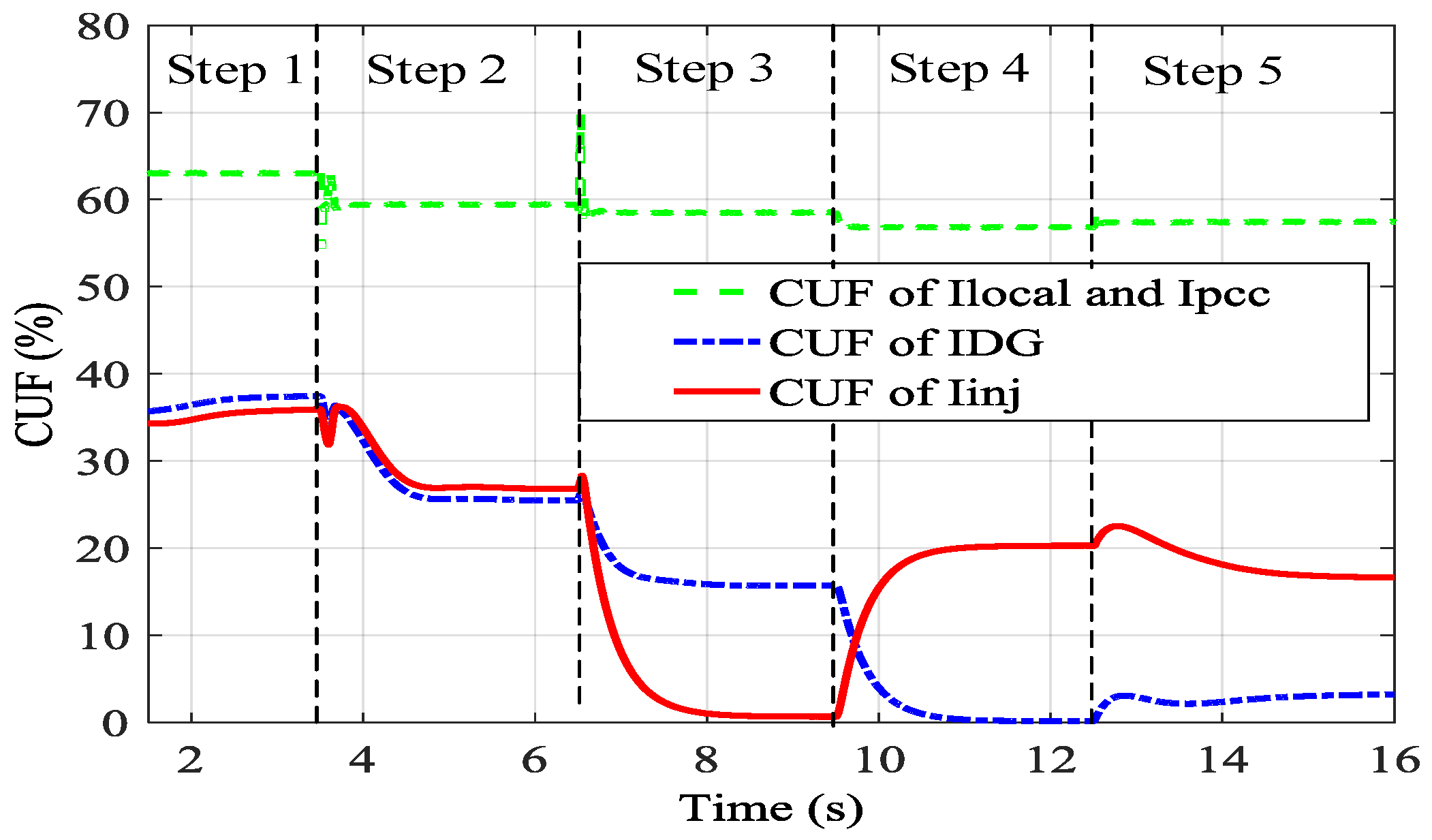
The VUFs and CUFs of the related voltages and currents are depicted in Figure 8 and Figure 9, respectively. Since an unbalanced nonlinear load is used in this study, both sequences of triple and other odd harmonics will be present [35]. Thus, the dominant harmonic components, selected for compensation in this paper, are third, fifth and seventh orders [20]. The amount of the negative and positive sequences of third and fifth harmonics of voltage and current are listed in Table 2 in different steps.
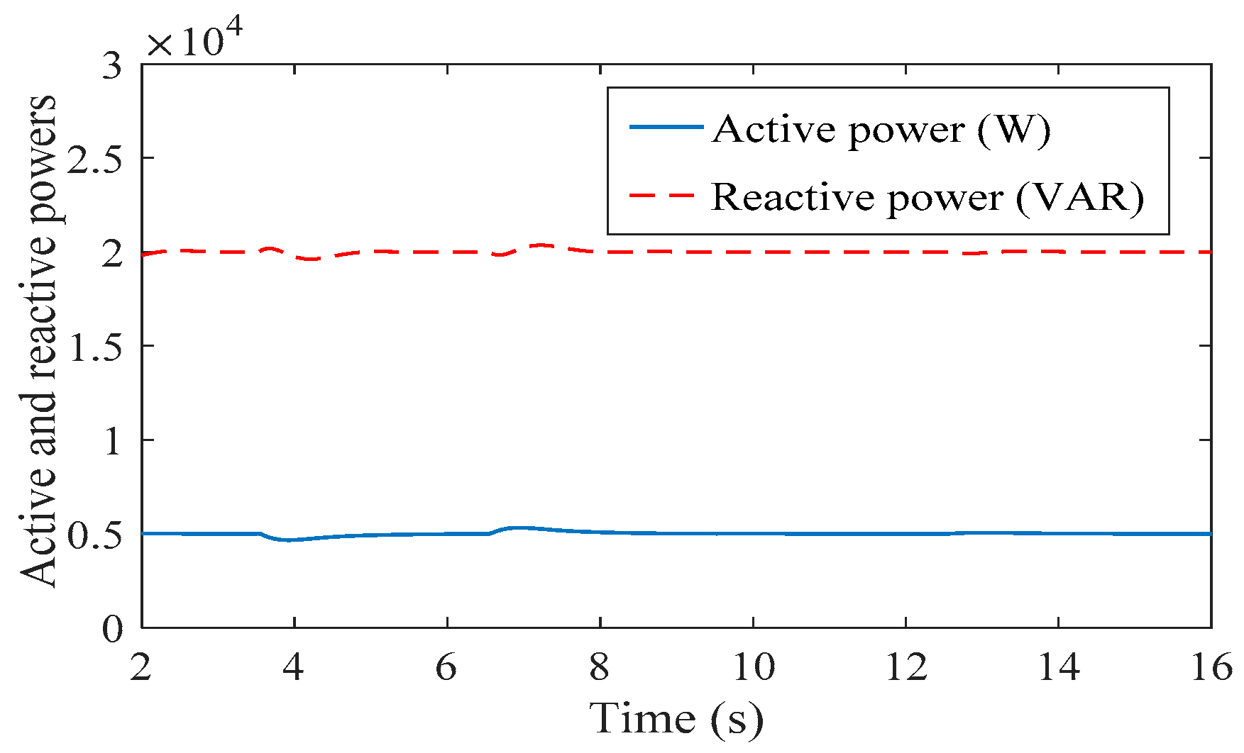
Note that due to the limitation of paper and table length, the seventh harmonic components are not presented in this Table. Furthermore, the capability of the controller in injecting the reference active and reactive powers to the grid is also investigated. Figure 10 shows that the grid-connected inverter can inject the reference active and reactive powers listed in Table 1 to the grid in different compensation modes. The details of the power quality compensation in the aforementioned steps are explained below:
Step 1: Mode 1 is activated in this step. Since the PCC voltage compensation is the aim of this step and mode, the PCC voltage waveform is depicted in Figure 11. As depicted in Figure 8 and Figure 11, the unbalance voltage of the PCC is compensated and the VUF of the VPCC is about 0.2%, which is below the standard limit of 2%. The compensation is achieved via the negative sequence virtual conductance which creates a low-impedance path for negative sequence current to pass through the DG-interfacing inverter. Therefore, IDG becomes unbalanced, as demonstrated by its CUF in Figure 9. Furthermore, as depicted in Figure 11 and Table 2, the harmonic contents of the PCC voltage are compensated. In order to show the effectiveness of the FPQC in this mode, the PCC voltage is also magnified in Step 5, when the PQC is inactive.
Step 2: in this interval, Mode 2 is applied to the inverter by setting the reference value of VC to 0 in the input of the unbalance compensation controller. The VC is used as feedback of the FPQC, and negative and harmonic sequence voltages with 180 phase degree difference with negative and harmonics sequences of VC are injected for compensation. Figure 12 shows the VC voltage in different steps, while this figure is magnified in Step 2 (VC compensation) and Step 5 (without compensation). Furthermore, as depicted in Figure 12 and Table 2, the harmonic compensation of VC is also achieved.
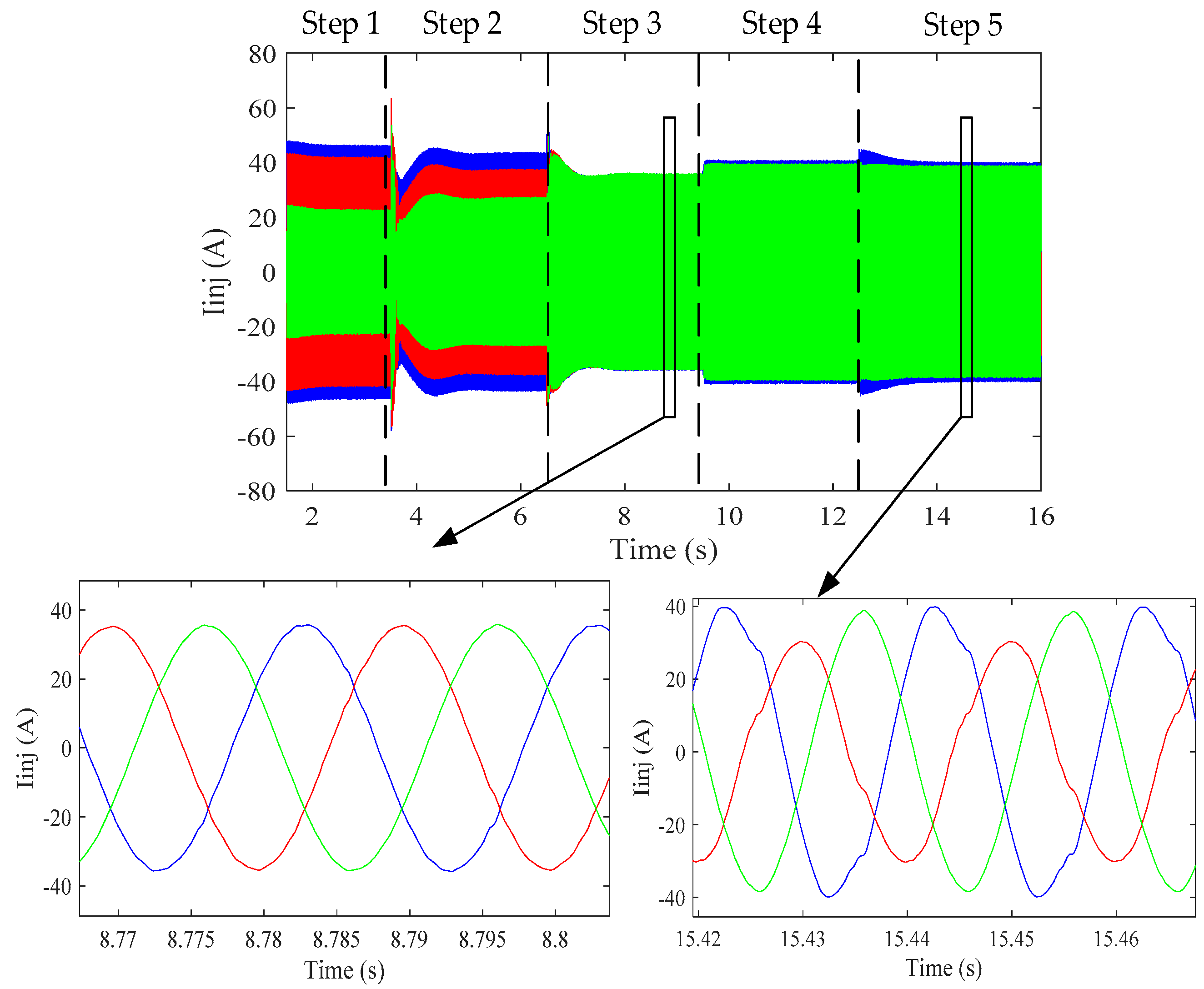
Step 3: in this interval, Mode 3 of power-quality improvement is selected by the “Mode Selector” switch. In this mode, the (ILocal-I2) is applied to the PQC, as depicted in Figure 2, and the DG generates the negative and harmonic sequences of the local load; hence, Iinj will be compensated, as illustrated by CUF (Figure 9), Table 3 and the Iinj waveform that is depicted in Figure 13. Figure 13 shows the magnified image of Iinj in Step 3 (Iinj compensation mode) and Step 5, when the PQC is deactivated for evaluating the performance of power-quality compensation in this mode and step.
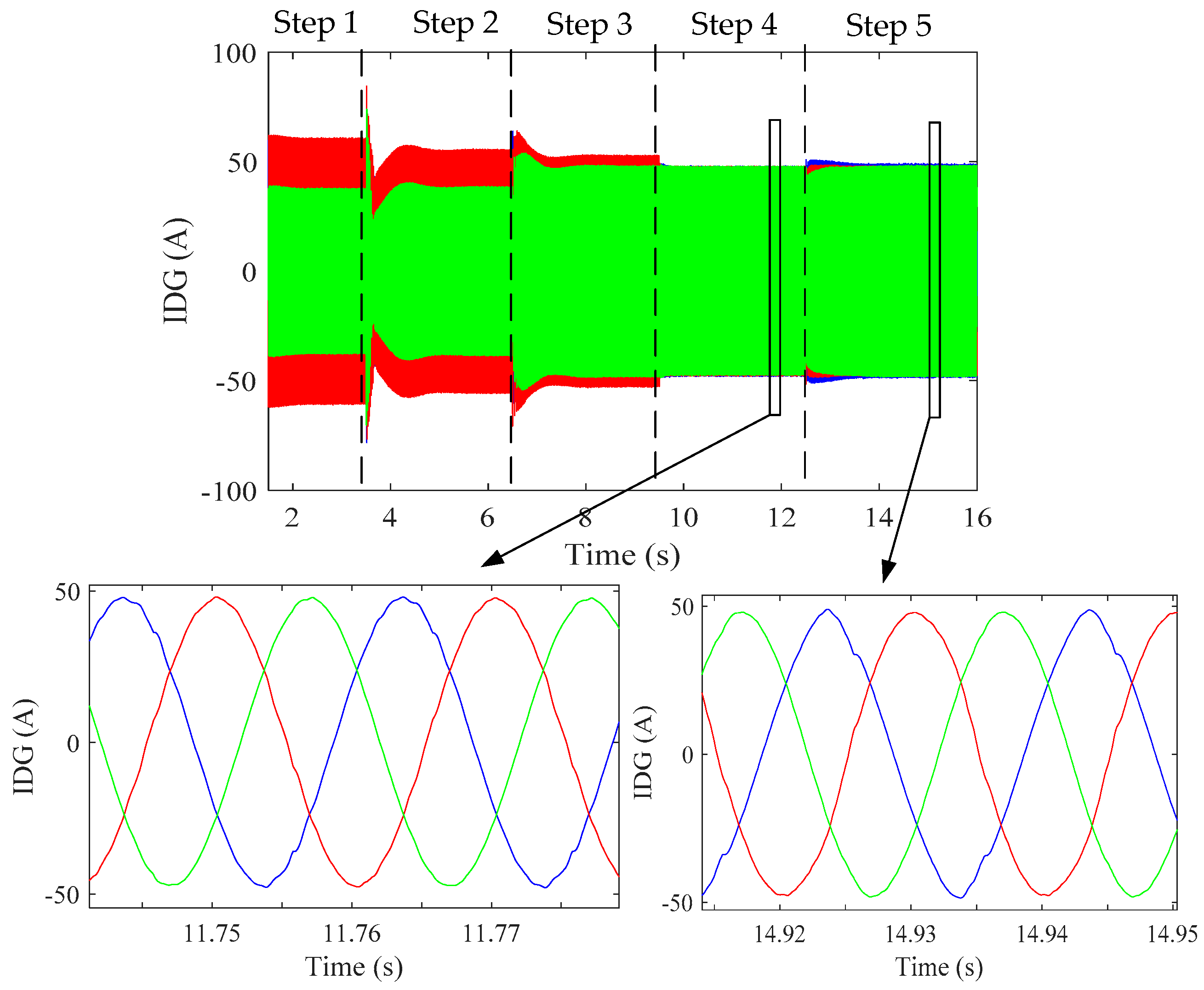
Step 4: in this mode, which is also called unbalance and harmonic rejection mode, the reference value of the I2 is chosen to be zero for the PQC controller. As depicted in Figure 9, the CUF of the IDG is approximately zero in this step. This fact is also demonstrated in Figure 14, which shows the waveform of IDG in different steps. In this figure, the waveform is also magnified in Steps 4 (IDG compensation mode) and 5 (without compensation); however, Iinj is unbalanced, with a high CUF equal to 30%. Since the unbalanced current passes through the impedances of the grid and the LCL filter, the VUFs of the VPCC and VC are high in this interval, as depicted in Figure 8. For harmonic compensation, as listed in Table 2, H3−, H3+, H5− and H5+ of VPCC and VC are increased, and the DG current is also compensated.
Step 5: in this interval, the unbalance compensation is deactivated. As shown in Figure 8, the VUF of the VPCC and VC is approximately 5.5%, which is higher than the standard limit of 2%. In order to show the effectiveness of the FPQC, the waveforms of voltage/current in this step are also depicted in Figure 11, Figure 12, Figure 13 and Figure 14. This step is used as a comparative study against methods without harmonic and unbalance compensation. For instance, as depicted in Figure 8, the VUF of VPCC and VC are about 5.8% in this step, which is higher than the standard limit of 2%. The results show the advantage of this method in comparison to the methods proposed in [23,24], in which the negative sequence compensation is not the object of these papers.
4.2. Islanded Operation of the MG
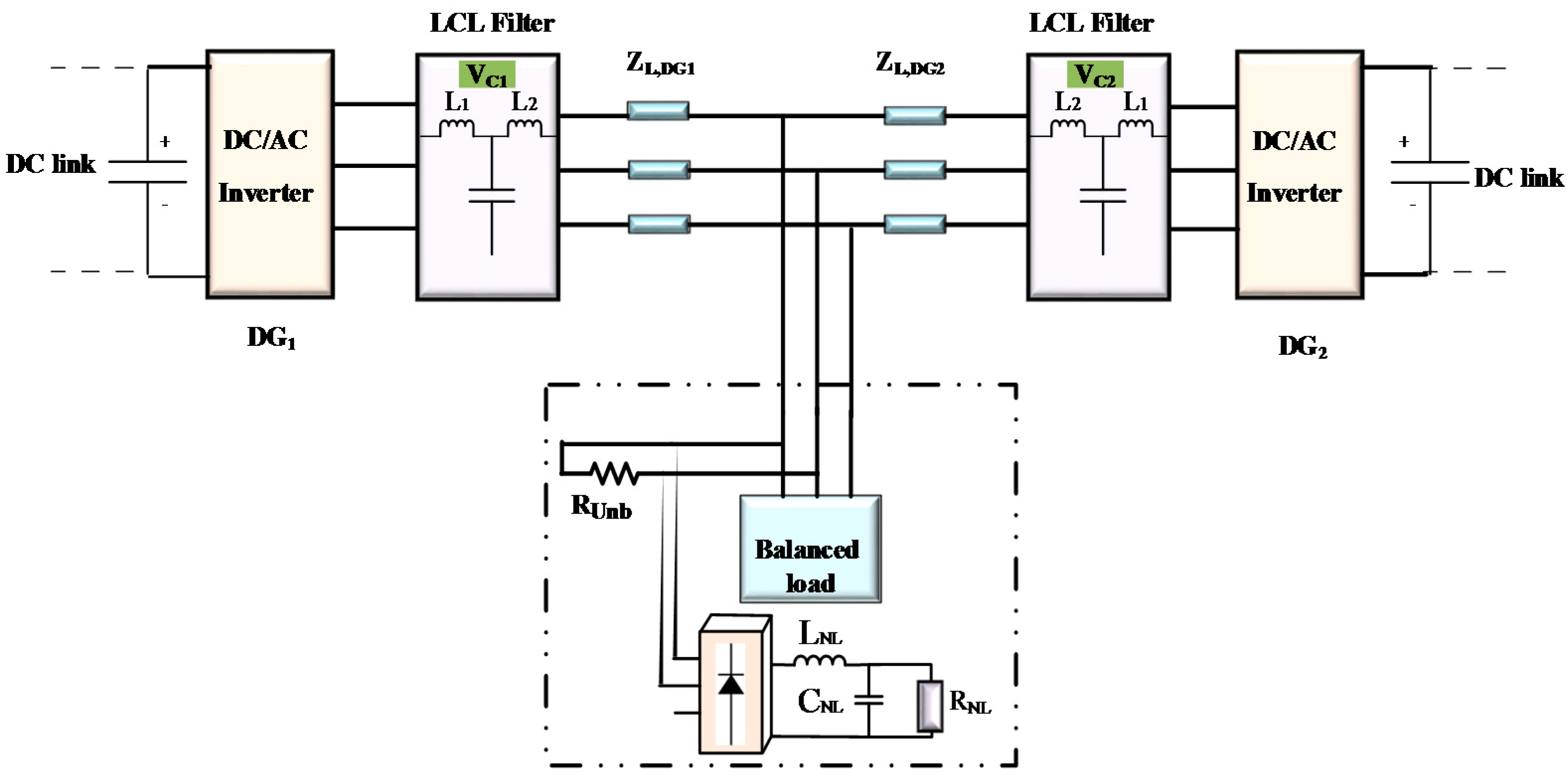
The simulated islanded MG includes two DG units, which supply balanced and unbalanced linear and nonlinear loads, as depicted in Figure 15. The system’s parameters are listed in Table 3.
In the case of the islanded MG, two unbalance compensation modes, namely, Mode X and Y, are applied.
- Mode X: unbalance and harmonic compensation of PCC.
- Mode Y: unbalance and harmonic compensation of VC.
In order to validate the performance of the controller in islanded operation of MG, the following four steps are used.
- ✓
- Step I:
For evaluating the effectiveness of the controller in improving the power quality of VPCC, the reference of PQC that is depicted in Figure 2 is set as (5), and Mode X is selected for DGs.
- ✓
- Step II:
In this step, the mode of PQC is changed from Mode X to Mode Y. In Mode Y, VC is used as feedback of the PQC, and its reference value is set to zero. The mode is similar to Mode 2 of the grid-connected inverter. The unbalanced linear load is considered as RUnb = 40 Ω.
- ✓
- Step III:
In this step, Mode Y is selected, and in order to evaluate the performance of the controller in changing the load, at t = 4 s the unbalance load is changed from RUnb = 40 Ω to RUnb = 20 Ω.
- ✓
- Step IV:
In this step, the PQC is deactivated in order to demonstrate the effectiveness of the control method in unbalance and harmonic comparison (compared to the conventional methods without harmonics and unbalance compensation).
Figure 16 shows the VUFs of the capacitor voltages of DG1 and DG2 (VC1 and VC2), and VPCC, while the harmonic contents of these variables are listed in Table 4. Figure 17 shows VPCC, and this figure is magnified in Step I (PCC compensation mode) and Step IV (without compensation) to evaluate the performance of the PQC. As depicted in Figure 16 and Figure 17 and Table 4, in Step I, the compensation of PCC voltage is achieved; for instance, the VUF of the voltage is below the standard limit of 2% when Mode X is applied.
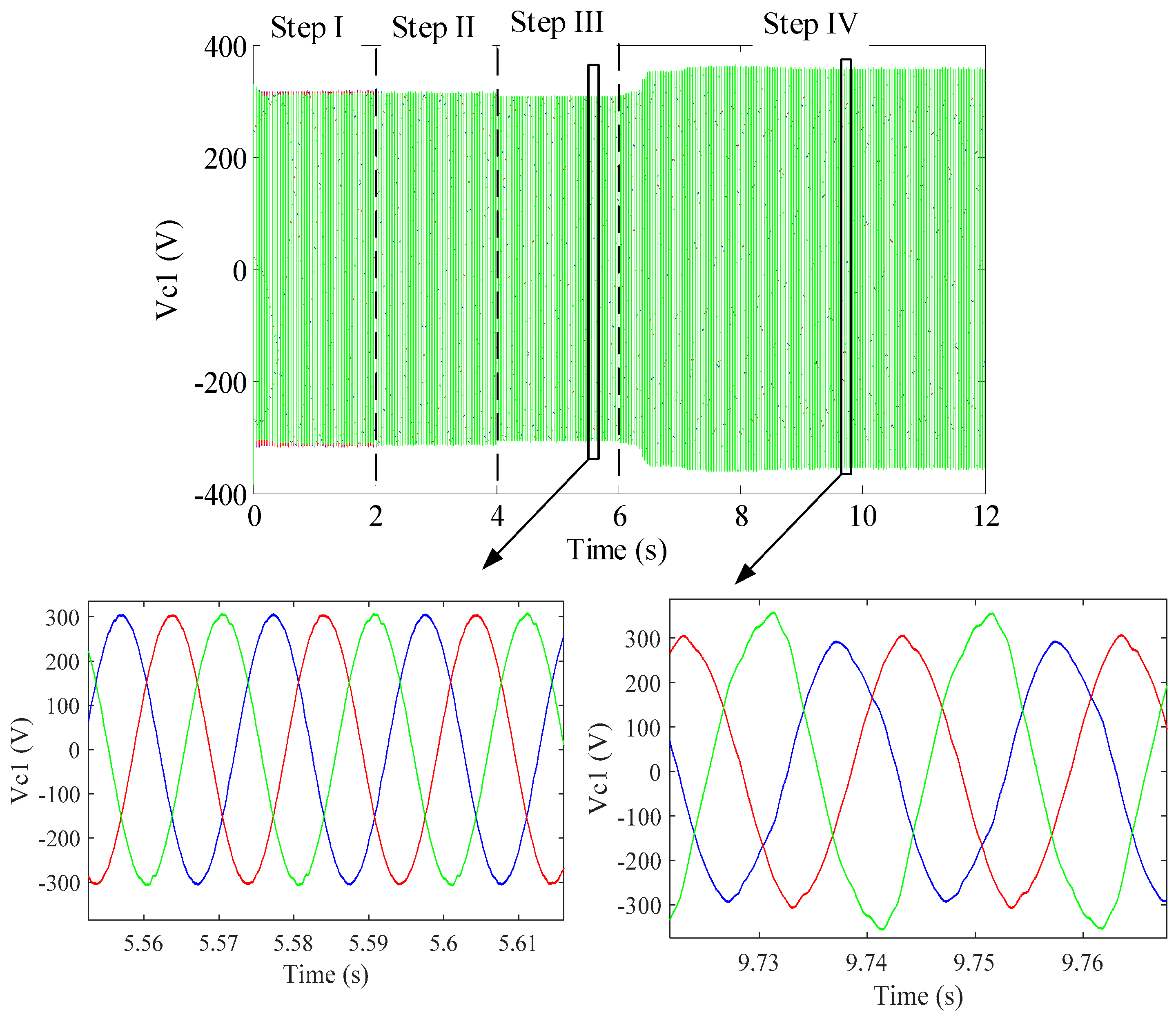
Furthermore, Figure 16 shows that the VUFs of VC1 and VC2 are improved in the Steps II and III, while the harmonic compensation becomes evident by selecting Mode Y, as presented in Table 4. In addition, according to Figure 16, the controller can compensate the negative sequence of the VC1 and VC2 when the load is doubled at t = 4 s. The harmonic contents of the VC1 and VC2 are compensated, according to Table 4. This is also shown in Figure 18, which depicts VC1 waveform in Steps III (VC compensation mode) and IV (without harmonics and unbalance compensation). As depicted in Figure 16, Figure 17 and Figure 18, if the unbalance compensation block is deactivated, the unbalance voltage problem can lead to some voltage quality problem for the microgrid. This shows the effectiveness of this applied method, in comparison to methods proposed in [23,24], in which the DGs can contribute only in harmonics compensation in a single-phase microgrid.
5. Conclusions
In this paper, a flexible unbalance and harmonic compensation scheme is proposed for the improvement of current and voltage quality in MGs. The performance of the method is investigated in both grid-connected and islanded operations of MGs. The simulation results show that by applying the proposed control scheme to a grid-connected MG, not only the active and reactive powers injection is achieved, but also control modes for harmonics and unbalance compensation of PCC voltage, DG voltages, DG output current or injected current of MGs can be obtained. According to the results, by selecting the PCC compensation mode, the VUF, H3+ and H3− of the PCC voltage are mitigated to about 0.2%, 1% and 1.1%, respectively, which are under the limitation of EN 50160 and IEEE 519 standards while these variables are approximately 5.8%, 3.3% and 2.6%, respectively, when the power-quality compensation is not activated (the case of conventional inverter control).
In order to validate the performance of the control system in islanded operation, the control method is applied to an MG which consists of two inverter-based DGs and unbalanced linear and nonlinear loads. The simulation results show that the PCC or DG voltages harmonic and unbalance compensation can be achieved, depending on the desired control goal. For better evaluation of the performance of the control method in harmonic and unbalance compensation, this control method is deactivated in one step. The results show that the VUF, H3− and H3+ of DG output voltages are approximately 0.3%, 0.025% and 0.05%, respectively, when the DG output voltages compensation is activated; furthermore, the results show that when the controller is deactivated, VUF, H3− and H3+ of DG output voltages are 13%, 3.3% and 3%, respectively.
By using the proposed controller, the DGs can contribute in unbalance and harmonic compensation of voltage or current, depending on the selected compensation mode. The proposed control can reduce the need for dedicated additional power-quality conditioners. For future work, the coordinated control of multiple DGs equipped with this control method can be examined.
Author Contributions
The design of the controller and simulation of the case study has been done by Seyyed Yousef Mousazadeh Mousavi under supervision of Alireza Jalilian and co-supervision of Mehdi Savaghebi and Josep M. Guerrero. The manuscript has been written by Seyyed Yousef Mousazadeh Mousavi and has been revised by other authors.
Conflicts of Interest
The authors declare no conflict of interest.
References
- Bose, B.K. Global Warming: Energy, Environmental Pollution, and the Impact of Power Electronics. IEEE Ind. Electron. Mag. 2010, 4, 6–17. [Google Scholar] [CrossRef]
- Mousazadeh, S.Y.; Savaghebi, M.; Beirami, A.; Jalilian, A.; Guerrero, J.M.; Chendan, L. Control of A Multi-Functional Inverter for Grid Integration of PV and Battery Energy Storage System. In Proceedings of the 2015 IEEE 10th International Symposium on Diagnostics Electrical Machines, Power Electronics and Drives (SDEMPED), Guarda, Portugal, 1–4 September 2015; pp. 474–480. [Google Scholar]
- Green, T.C.; Prodanović, M. Control of inverter-based micro-grids. Electr. Power Syst. Res. 2007, 77, 1204–1213. [Google Scholar] [CrossRef]
- Guerrero, J.M.; Chandorkar, M.; Lee, T.; Loh, P.C. Advanced Control Architectures for Intelligent Microgrids Part I: Decentralized and Hierarchical Control. IEEE Trans. Ind. Electron. 2013, 60, 1254–1262. [Google Scholar] [CrossRef]
- Chowdhury, S.; Crossley, P. Microgrids and Active Distribution Networks; The Institution of Engineering and Technology (IET): Michael Faraday House, Stevenage, UK, 2009; ISBN 978-1-84919-014-5. [Google Scholar]
- Mohd, A.; Ortjohann, E.; Morton, D.; Omari, O. Review of control techniques for inverters parallel operation. Electr. Power Syst. Res. 2010, 80, 4734–4749. [Google Scholar] [CrossRef]
- Reznik, A.; Simoes, M.G.; Al-Durra, A.; Muyeen, S.M. LCL Filter Design and Performance Analysis for Grid-Interconnected Systems. IEEE Trans. Ind. Appl. 2014, 50, 1225–1232. [Google Scholar] [CrossRef]
- Rockhill, A.A.; Liserre, M.; Teodorescu, R.; Rodriguez, P. Grid-Filter Design for a Multimegawatt Medium-Voltage Voltage-Source Inverter. IEEE Trans. Ind. Electron. 2011, 58, 1205–1217. [Google Scholar] [CrossRef] [Green Version]
- Savaghebi, M.; Jalilian, A.; Vasquez, J.C.; Guerrero, J.M. Autonomous Voltage Unbalance Compensation in an Islanded Droop-Controlled Microgrid. IEEE Trans. Ind. Electron. 2013, 60, 1390–1402. [Google Scholar] [CrossRef]
- Baggini, A. Handbook of Power Quality; John Wiley & Sons: New York, NY, USA, 2008. [Google Scholar]
- Bouloumpasis, I.; Vovos, P.; Georgakas, K.; Vovos, N.A. Current harmonics compensation in microgrids exploiting the power electronics interfaces of renewable energy sources. Energies 2015, 8, 2295–2311. [Google Scholar] [CrossRef]
- Nejabatkhah, F.; Li, Y.W.; Wu, B. Control Strategies of Three-Phase Distributed Generation Inverters for Grid Unbalanced Voltage Compensation. IEEE Trans. Power Electron. 2016, 31, 5228–5241. [Google Scholar]
- Ma, T.T.; Chiang, S.J. A multi-functional power conditioner with real-time voltage regulation for energy saving. Eur. Trans. Electr. Power 2008, 18, 15–28. [Google Scholar] [CrossRef]
- Milanes-Montero, M.I.; Barrero-Gonzalez, F.; Pando-Acedo, J.; Gonzalez-Romera, E.; Romero-Cadaval, E.; Moreno-Munoz, A. Active, Reactive and Harmonic Control for Distributed Energy Micro-Storage Systems in Smart Communities Homes. Energies 2017, 10, 448. [Google Scholar] [CrossRef]
- Mosazadeh, S.Y.; Fathi, S.H.; Hajizadeh, M.; Sheykholeslami, A.R. Adaptive Hysteresis Band Controlled Grid Connected PV System with Active Filter Function. In Proceedings of the 2012 International Conference on Power Engineering and Renewable Energy (ICPERE), Bally, Indonesia, 3–5 July 2012. [Google Scholar]
- Cheng, P.T.; Chen, C.A.; Lee, T.L.; Kuo, S.Y. A Cooperative Imbalance Compensation Method for Distributed-Generation Interface Converters. IEEE Trans. Ind. Appl. 2009, 45, 805–815. [Google Scholar] [CrossRef]
- El-Naggar, A.; Erlich, I. Control approach of three-phase grid connected PV inverters for voltage unbalance mitigation in low-voltage distribution grids. IET Renew. Power Gener. 2016, 10, 1577–1586. [Google Scholar] [CrossRef]
- Tang, F.; Zhou, X.; Meng, L.; Guerrero, J.M.; Vasquez, J.C. Secondary Voltage Unbalance Compensation for Three-Phase Four-Wire Islanded Microgrids. In Proceedings of the 2014 11th International Multi-Conference on Systems, Signals & Devices (SSD), Barcelona, Spain, 11–14 February 2014; pp. 1–5. [Google Scholar]
- Savaghebi, M.; Jalilian, A.; Vasquez, J.C.; Guerrero, J.M. Secondary Control Scheme for Voltage Unbalance Compensation in an Islanded Droop-Controlled Microgrid. IEEE Trans. Smart Grid 2012, 3, 797–807. [Google Scholar] [CrossRef]
- Savaghebi, M.; Jalilian, A.; Vasquez, J.C.; Guerrero, J.M. Secondary control for voltage quality enhancement in microgrids. IEEE Trans. Smart Grid 2012, 3, 1893–1902. [Google Scholar] [CrossRef]
- Meng, L.; Tang, F.; Savaghebi, M.; Vasquez, J.C.; Guerrero, J.M. Tertiary Control of Voltage Unbalance Compensation for Optimal Power Quality in Islanded Microgrids. IEEE Trans. Energy Convers. 2014, 29, 802–815. [Google Scholar] [CrossRef]
- Hamzeh, M.; Karimi, H.; Mokhtari, H. Harmonic and Negative-Sequence Current Control in an Islanded Multi-Bus MV Microgrid. IEEE Trans. Smart Grid 2014, 5, 167–176. [Google Scholar] [CrossRef]
- He, J.; Li, Y.W.; Blaabjerg, F. Flexible Microgrid Power Quality Enhancement Using Adaptive Hybrid Voltage and Current Controller. IEEE Trans. Ind. Electron. 2014, 61, 2784–2794. [Google Scholar] [CrossRef]
- He, J.; Li, Y.W. Hybrid Voltage and Current Control Approach for DG-Grid Interfacing Converters with LCL filters. IEEE Trans. Ind. Electron. 2013, 60, 1797–1809. [Google Scholar] [CrossRef]
- Akagi, H.; Kanazawa, Y.; Nabae, A. Instantaneous Reactive Power Compensators Comprising Switching Devices without Energy Storage Components. IEEE Trans. Ind. Appl. 1984, 203, 625–630. [Google Scholar] [CrossRef]
- Wang, X.; Blaabjerg, F.; Chen, Z. Autonomous Control of Inverter-Interfaced Distributed Generation Units for Harmonic Current Filtering and Resonance Damping in an Islanded Microgrid. IEEE Trans. Ind. Appl. 2014, 50, 452–461. [Google Scholar] [CrossRef]
- Savaghebi, M.; Vasquez, J.C.; Jalilian, A.; Guerrero, J.M.; Lee, T.L. Selective harmonic virtual impedance for voltage source inverters with LCL filter in microgrids. In Proceedings of the 2012 IEEE Energy Conversion Congress and Exposition (ECCE), Raleigh, NC, USA, 15–20 September 2012; pp. 1960–1965. [Google Scholar]
- Lee, T.L.; Hu, S.H.; Chan, Y.H. D-STATCOM with Positive-Sequence Admittance and Negative-Sequence Conductance to Mitigate Voltage Fluctuations in High-Level Penetration of Distributed-Generation Systems. IEEE Trans. Ind. Electron. 2013, 60, 1417–1428. [Google Scholar] [CrossRef]
- Rodriguez, P.; Timbus, A.V.; Teodorescu, R.; Liserre, M.; Blaabjerg, F. Flexible Active Power Control of Distributed Power Generation Systems during Grid Faults. IEEE Trans. Ind. Electron. 2007, 54, 2583–2592. [Google Scholar] [CrossRef]
- Savaghebi, M.; Vasquez, J.C.; Jalilian, A.; Guerrero, J.M.; Lee, T.L. Selective compensation of voltage harmonics in grid-connected microgrids. Math. Comput. Simul. 2013, 91, 221–228. [Google Scholar] [CrossRef]
- He, J.; Li, Y.W.; Munir, M.S. A Flexible Harmonic Control Approach through Voltage-Controlled DG-Grid Interfacing Converters. IEEE Trans. Ind. Electron. 2012, 59, 444–455. [Google Scholar] [CrossRef]
- Lorzadeh, I.; Askarian Abyaneh, H.; Savaghebi, M.; Bakhshai, A.; Guerrero, J.M. Capacitor Current Feedback-Based Active Resonance Damping Strategies for Digitally-Controlled Inductive-Capacitive-Inductive-Filtered Grid-Connected Inverters. Energies 2016, 9, 642. [Google Scholar] [CrossRef]
- Yu, Y.; Li, H.; Li, Z.; Zhao, Z. Modeling and analysis of resonance in LCL-type grid-connected inverters under different control schemes. Energies 2017, 10, 104. [Google Scholar] [CrossRef]
- Tan, P.C.; Loh, P.C.; Holmes, D.G. High performance harmonic extraction algorithm for a 25 kV traction power conditioner. IEEE Proc. Electr. Power Appl. 2004, 151, 505–512. [Google Scholar] [CrossRef]
- Dugan, R.C.; McGranaghan, M.F.; Beaty, H.W. Electrical Power Systems Quality; McGraw-Hill: New York, NY, USA, 1996. [Google Scholar]
Figure 1.
Diagram of the proposed flexible power-quality improvement scheme.

Figure 2.
Proposed flexible power-quality controller, (a) general scheme of FPQC; and (b) SOGI-based controller.
Figure 2.
Proposed flexible power-quality controller, (a) general scheme of FPQC; and (b) SOGI-based controller.
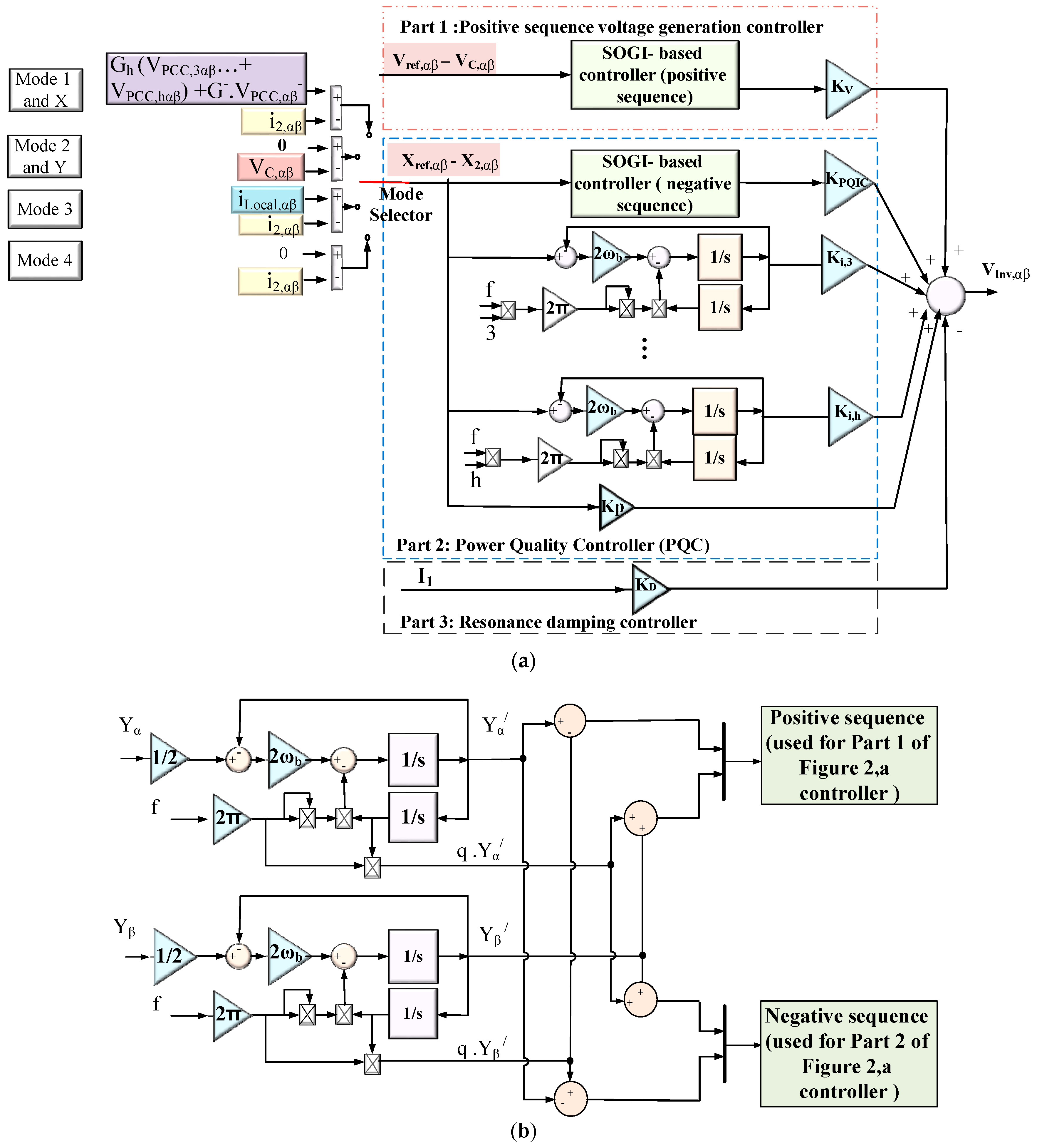
Figure 3.
Positive sequence voltage-controller diagram.

Figure 4.
FNS&H current-controller diagram.
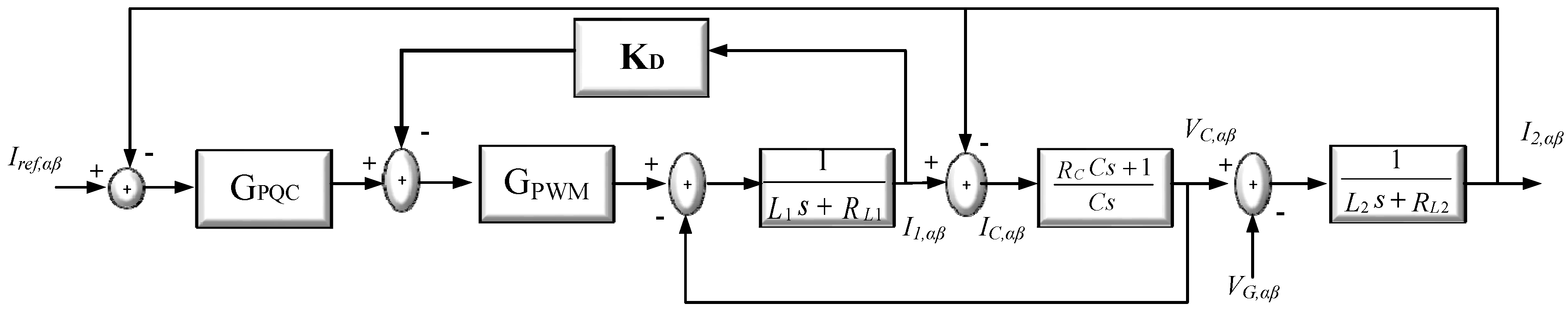
Figure 5.
Bode diagram of GPSCV.
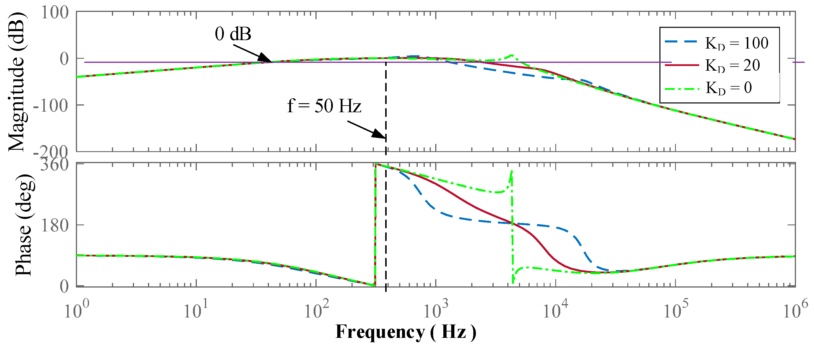
Figure 6.
Bode diagram of GONHC(s).
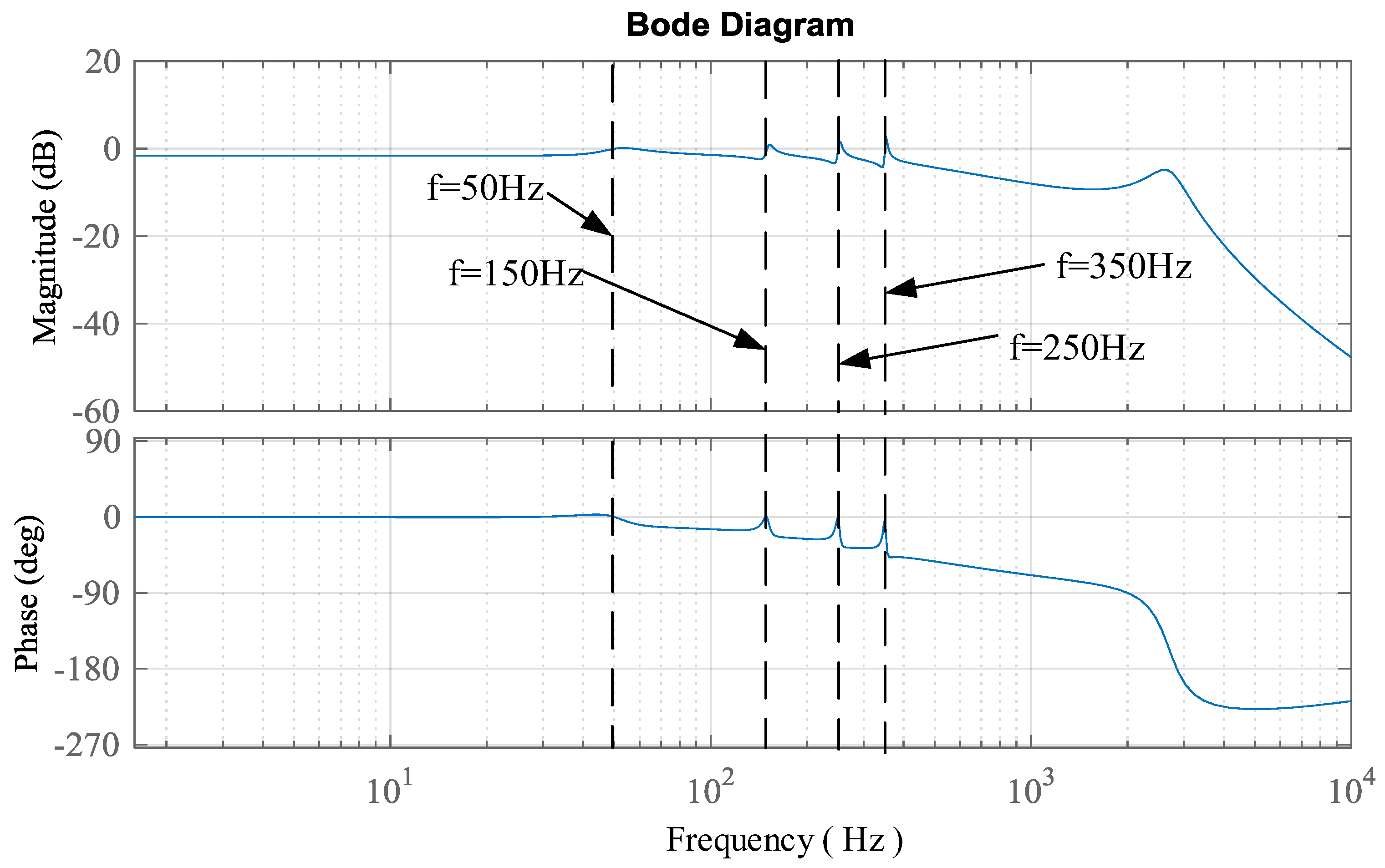
Figure 7.
Simulated grid-connected MG with unbalanced linear and nonlinear local and PCC loads.

Figure 8.
VUF curves of voltages in grid-connected MG.
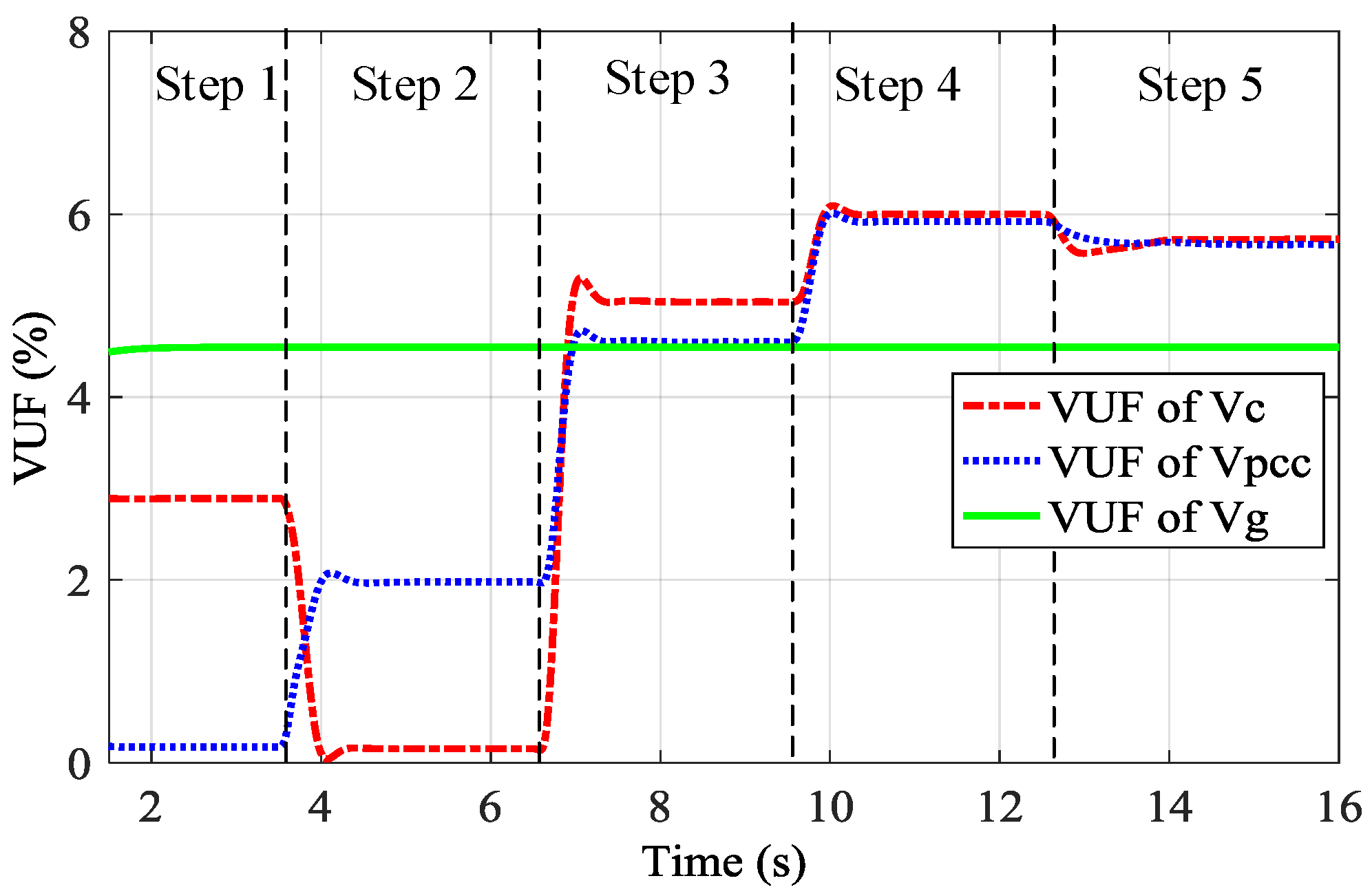
Figure 9.
CUF curves of currents in grid-connected MG.

Figure 10.
Active and reactive powers of DG.

Figure 11.
VPCC in Step 1 and Step 5 (without compensation) of unbalance compensation.
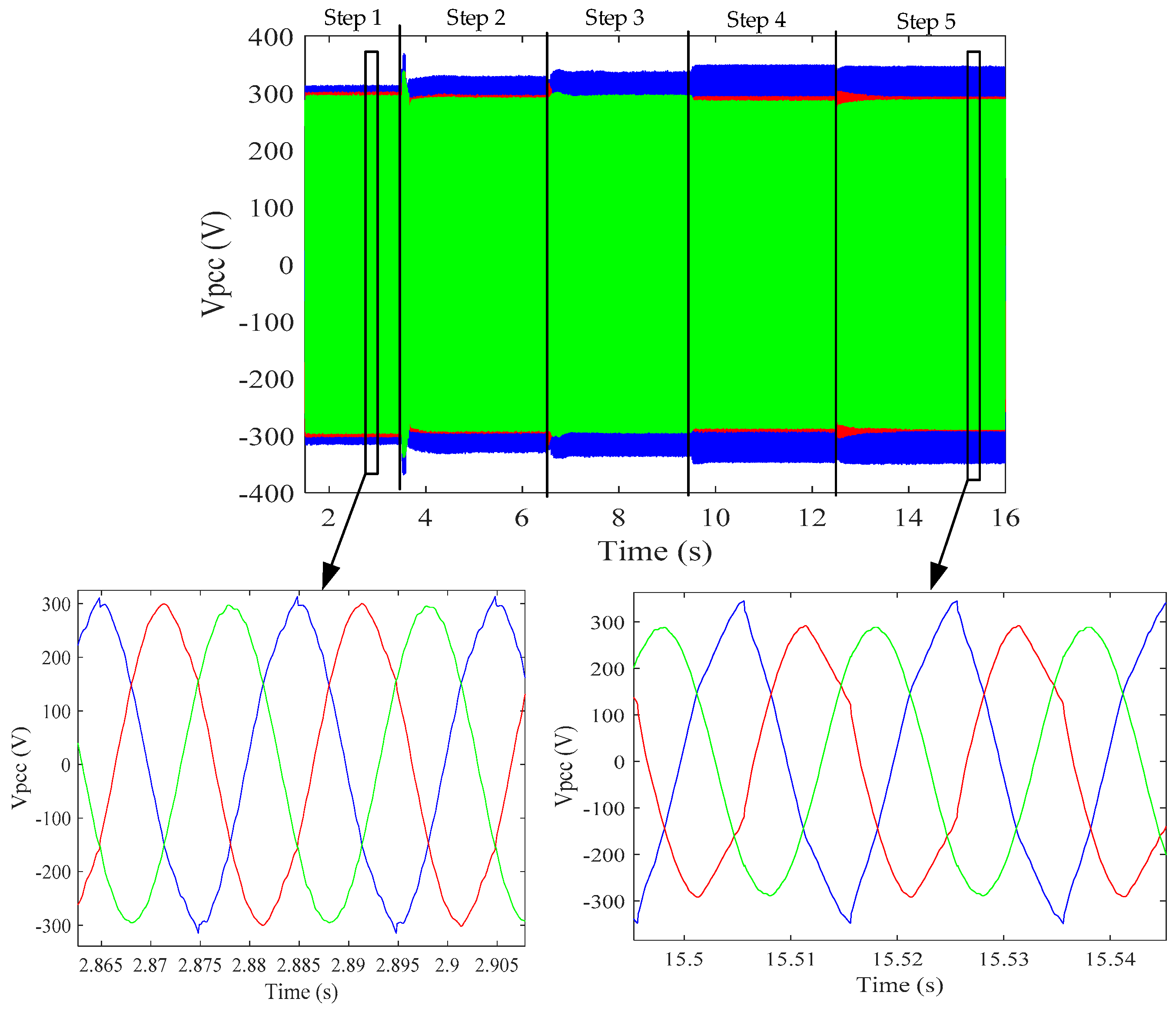
Figure 12.
VC waveform in Step 2 and Step 5 (without compensation) of unbalance compensation.
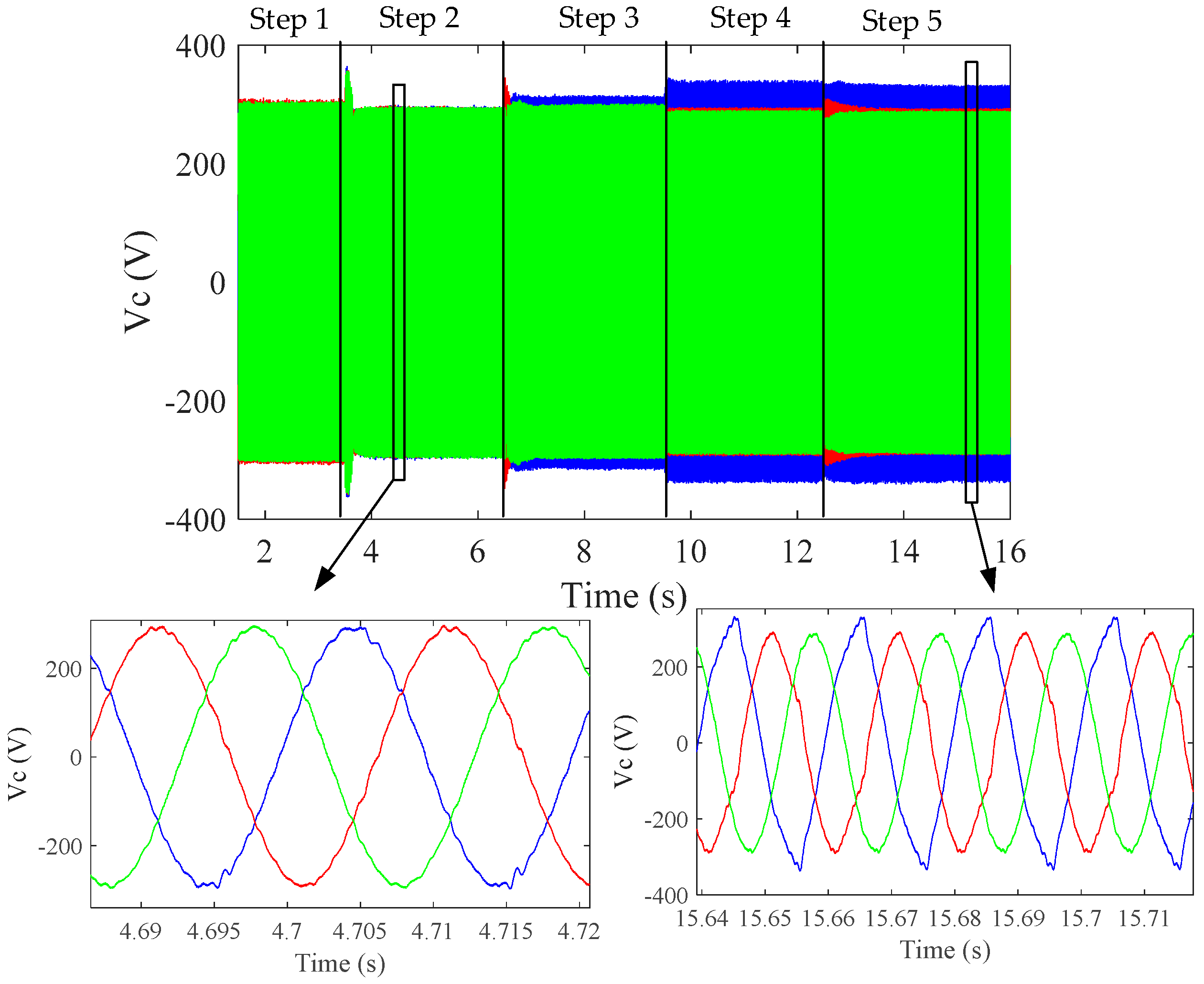
Figure 13.
Iinj in Step 3 and Step 5 (without compensation) of unbalance compensation.

Figure 14.
IDG in Step 4 and Step 5 (without compensation) of unbalance compensation.

Figure 15.
Islanded MG with two DG units.

Figure 16.
VUFs of related voltages in the islanded microgrid.
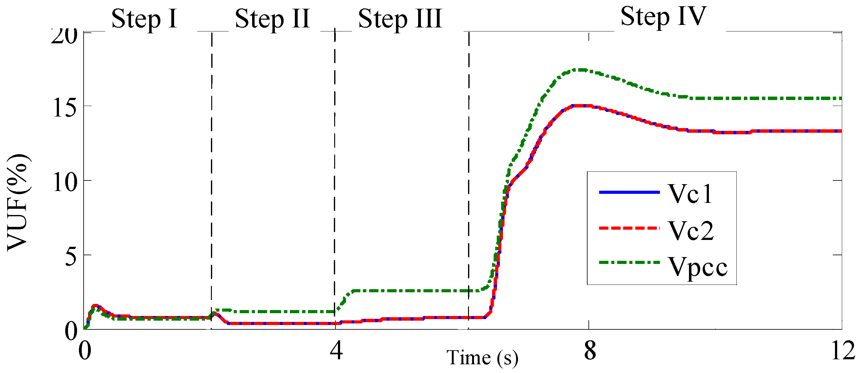
Figure 17.
VPCC in Step I (VPCC compensation) and Step IV (without compensation) for islanded MG.
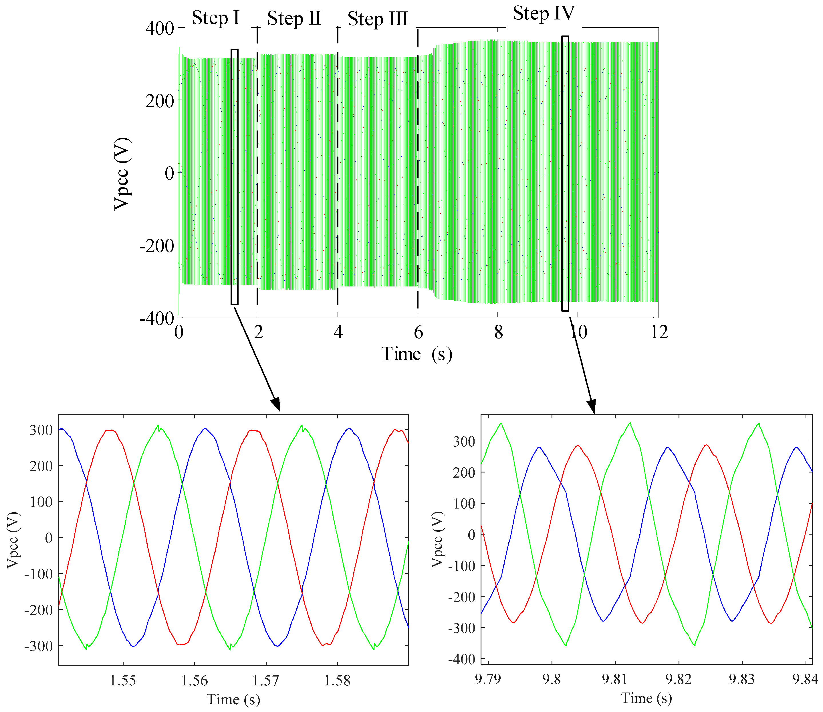
Figure 18.
VC1 in Step III (VC compensation) and Step IV (without compensation) for islanded MG.

Table 1.
Parameters of grid-connected MG.
| DC Link Voltage | LCL Filter (L1/C/L2) | Voltage/Frequency | ||||
|---|---|---|---|---|---|---|
| 650 V | 2.5 mH/20 μF/1.5 Mh | 230 V/50 Hz | ||||
| Nonlinear load | Line impedance | Unbalanced linear local and PCC load | ||||
| CNL (μF) | RNL (Ω) | LNL (mH) | ZLG (Ω) | Runb (Ω) | ||
| 235 | 114 | 0.084 | 0.95j + 1 | 20 | ||
| active and reactive power powers refrence power | Switching frequency | Pulse Width modulatin (PWM) delay | ||||
| Active power reference | Reactive power reference | fs | Ts | |||
| 20 kW | 5 kVAR | 10 kHz | 100 μs | |||
| Parameters of controller | ||||||
| Active power droop coefficients | Reactive power droop coefficients | |||||
| mP | mI | nP | nI | |||
| 1 × 10⁻⁵ rad·s−1 | 1 × 10⁻⁴ ω | 0.05 | 0.1 | |||
| Voltage and current controllers parameters | ||||||
| KV | KUUC | KI,3/KI,5/KI,7 | KP | KD | ||
| 4 | 700 | 500/300/300 | 4 | 20 | ||
| Virtual admittance for harmonic and unbalance compensation | Virtual impedance for fundamental component | |||||
| G− | Gh | Rv | Lv | |||
| 25 Ω−1 | 1 Ω−1 | 0.1 Ω | 2 mH | |||
Table 2.
Harmonic contents of VPCC, VC, IDG and Iinj in different steps for grid-connected MG.
| Harmonics | VPCC | VC | IDG | Iinj | |||||||||||||
|---|---|---|---|---|---|---|---|---|---|---|---|---|---|---|---|---|---|
| Steps | H3− | H3+ | H5− | H5+ | H3− | H3+ | H5− | H5+ | H3− | H3+ | H5− | H5+ | H3− | H3+ | H5− | H5+ | |
| Step 1 | 1.1 | 1 | 0.8 | 0.8 | 2.1 | 2.1 | 2.2 | 2.15 | 8 | 7.5 | 5.5 | 5.25 | 5 | 4.9 | 3.75 | 3.5 | |
| Step 2 | 1.5 | 1.3 | 1.5 | 1.2 | 0.05 | 0.05 | 0.05 | 0.03 | 6 | 5.5 | 3.85 | 3.25 | 2.2 | 2 | 1.5 | 1 | |
| Step 3 | 2.2 | 1.75 | 2 | 1.55 | 1.5 | 1.05 | 1.15 | 0.9 | 4.2 | 3.8 | 2.3 | 1.9 | 0.3 | 0.2 | 0.2 | 0.2 | |
| Step 4 | 3.75 | 2.8 | 2.8 | 2 | 3.8 | 3 | 2.85 | 2 | 0.15 | 0.08 | 0.1 | 0.1 | 5.3 | 4.15 | 2.5 | 1.75 | |
| Step 5 | 3.3 | 2.6 | 2.5 | 2 | 3.15 | 2.7 | 2.3 | 2 | 1.75 | 1.4 | 1.3 | 1 | 4 | 2.9 | 1.85 | 1.6 | |
Table 3.
Parameters of the simulated islanded MG.
| DC Link Voltage | LCL Filter (L1/C/L2) for Both DGs | Voltage/Frequency | |||
|---|---|---|---|---|---|
| 650 V | 2.5 mH/20 μF/1.5 mH | 230 V/50 Hz | |||
| Nonlinear load | Line impedance for both DGs | Unbalanced linear local and PCC load | |||
| CNL (μF) | RNL (Ω) | LNL (mH) | ZLG (Ω) | ZL (Ω) | |
| 235 | 114 | 0.084 | 0.95j + 1 | 40/20 | |
| Parameter of controller | |||||
| Active power droops coefficients | Reactive power droops coefficients | ||||
| mP | mI | nP | nI | ||
| 1 × 10⁻⁵ rad·s−1 | 1 × 10⁻⁴ | 0.05 | 0 | ||
| Voltage and current controllers parameters | |||||
| KV | KUUC | KI,3/KI,5/KI,7 | KP | KD | |
| 4 | 700 | 500/300/300 | 4 | 20 | |
| Virtual admittance for harmonics and unbalance compensation | Virtual impedance for fundamental component | ||||
| G− | Gh | Rv | Lv | ||
| 1.8 Ω−1 | 0.8 Ω−1 | 0.1 Ω | 2 mH | ||
Table 4.
Harmonic contents of VPCC, VC1 and VC2 in different steps for islanded MG.
| Harmonics | VPCC | VC1 | VC2 | ||||||||||
|---|---|---|---|---|---|---|---|---|---|---|---|---|---|
| Steps | H3− | H3+ | H5− | H5+ | H3− | H3+ | H5− | H5+ | H3− | H3+ | H5− | H5+ | |
| Step I | 0.65 | 0.65 | 0.45 | 0.45 | 1.1 | 0.95 | 1.05 | 1.03 | 1 | 0.95 | 1.05 | 1.04 | |
| Step II | 1.05 | 1 | 1 | 0.95 | 0.02 | 0.042 | 0.013 | 0.02 | 0.015 | 0.04 | 0.015 | 0.015 | |
| Step III | 1.1 | 1.05 | 1.05 | 0.9 | 0.025 | 0.05 | 0.018 | 0.03 | 0.02 | 0.05 | 0.02 | 0.025 | |
| Step IV | 4 | 1 | 1.2 | 1.6 | 3.3 | 3 | 0.6 | 1.05 | 3.3 | 3 | 0.6 | 1.5 | |
© 2017 by the authors. Licensee MDPI, Basel, Switzerland. This article is an open access article distributed under the terms and conditions of the Creative Commons Attribution (CC BY) license (http://creativecommons.org/licenses/by/4.0/).
Share and Cite
MDPI and ACS Style
Mousazadeh Mousavi, S.Y.; Jalilian, A.; Savaghebi, M.; Guerrero, J.M. Flexible Compensation of Voltage and Current Unbalance and Harmonics in Microgrids. Energies 2017, 10, 1568. https://doi.org/10.3390/en10101568
AMA Style
Mousazadeh Mousavi SY, Jalilian A, Savaghebi M, Guerrero JM. Flexible Compensation of Voltage and Current Unbalance and Harmonics in Microgrids. Energies. 2017; 10(10):1568. https://doi.org/10.3390/en10101568
Chicago/Turabian StyleMousazadeh Mousavi, Seyyed Yousef, Alireza Jalilian, Mehdi Savaghebi, and Josep M. Guerrero. 2017. "Flexible Compensation of Voltage and Current Unbalance and Harmonics in Microgrids" Energies 10, no. 10: 1568. https://doi.org/10.3390/en10101568
Note that from the first issue of 2016, this journal uses article numbers instead of page numbers. See further details here.