Development of Sliding Mode Controller for a Modified Boost Ćuk Converter Configuration


1
Department of Electrical and Electronics Engineering, University of Johannesburg, Auckland Park 2092, South Africa
2
Department of Electrical Engineering and Mechatronics, FEI TU of Košice, Letná 9, 04200 Košice, Slovakia
3
Centre for Reliable Power Electronics (CORPE), Department of Energy Technology, Aalborg University, 9000 Aalborg, Denmark
*
Author to whom correspondence should be addressed.
Energies 2017, 10(10), 1513; https://doi.org/10.3390/en10101513
Submission received: 18 June 2017
/
Revised: 11 July 2017
/
Accepted: 13 July 2017
/
Published: 29 September 2017
(This article belongs to the Special Issue Energy Storage Systems and Power Conversion Electronics for E-Transportation and Smart Grid)
Abstract
:This paper introduces a sliding mode control (SMC)-based equivalent control method to a novel high output gain Ćuk converter. An additional inductor and capacitor improves the efficiency and output gain of the classical Ćuk converter. Classical proportional integral (PI) controllers are widely used in direct current to direct current (DC-DC) converters. However, it is a very challenging task to design a single PI controller operating in different loads and disturbances. An SMC-based equivalent control method which achieves a robust operation in a wide operation range is also proposed. Switching frequency is kept constant in appropriate intervals at different loading and disturbance conditions by implementing a dynamic hysteresis control method. Numerical simulations conducted in MATLAB/Simulink confirm the accuracy of analysis of high output gain modified Ćuk converter. In addition, the proposed equivalent control method is validated in different perturbations to demonstrate robust operation in wide operation range.
1. Introduction
Direct current to direct current (DC-DC) converters play a vital role in electrical systems due to the increasing penetration of renewable sources in electrical networks. In addition to high efficiency and reliability requirements, robust performance of the converter in a wide operating range is of great importance, since DC-DC converters are also used in diverse special-purpose applications, such as electrical vehicles, DC motor drives, and telecommunication systems.
Different DC-DC converter topologies can be encountered in the literature. Classical converter topologies suffer from the lack of voltage gain ratio. Higher output voltage gain ratio with improved efficiency increases the performance of the converter, which is especially crucial for solar applications [1]. Diverse DC-DC converter topologies are proposed in [2,3,4,5,6,7,8,9] to improve the voltage gain ratio and efficiency. Important voltage lift methods are also reviewed and compared in [10].
A DC-DC converter circuit topology must be upgraded for higher voltage output gain and improved efficiency, lowering the conduction losses, designing a smaller size converter, and minimizing voltage and current stress on the semiconductor switch. In addition to circuit modification for achieving the above goals, controller structure is also of great importance to improve the performance, robustness, and reliability in a wide operation range. Unfortunately, these converters are still bottlenecked in terms of system reliability and performance [1]. In addition to circuit and controller design requirements, the availability and reliability of a complete system in harsh environments is also an important task to be considered. The studies given in [11,12,13,14] outline the harsh environment requirements of electronic circuits and implement different types of electronic circuit applications for automotive systems.
High performance control of a DC-DC converter is a challenge for both control engineering and power electronics practitioners due to the highly nonlinear nature of DC-DC converters. Furthermore, fast response in terms of rejection of load variations, input voltage disturbances, and parameter uncertainties is mandatory for robust operation.
A Ćuk converter is a kind of buck/boost converter topology; the inverted output is either lower or higher than the input voltage. Different modifications are applied to classical Ćuk circuit [15,16] to enhance the performance. Modeling and control of Ćuk converters has been investigated with different approaches. Linear methods [17,18] and proportional integral (PI) controllers [19] are well-known design procedures with ease of implementation. However, these classical methods do not guarantee the stability and high performance in different perturbations due to highly nonlinear behavior of Ćuk converters. Thus, different nonlinear control algorithms are also implemented in Ćuk converters to overcome this drawback, such as passivity-based control [20], neural networks [21], direct control methods [22], fuzzy logic [23], and sliding mode control (SMC) [24].
SMC for variable structure systems [25] is a robust control method of nonlinear systems due to its insensitivity to parameter variations, fast dynamic response, and ease of implementation. SMC was first applied to DC-DC converters in [26,27], and many diverse implementation examples are available in [27]. Design criteria for SMC application to DC-DC converters is outlined in [28]. SMC-based equivalent controllers are applied to buck/boost and Ćuk converter topologies in [29,30]. However, SMC is not popularly implemented in DC-DC converters due to its unavailability of integrated circuit forms for power electronic applications. Moreover, its variable switching frequency (SF) behavior depending on the converter parameters and operation regions complicates electromagnetic interference filter design and practical implementation. A scheme given in [31] outlines the SF fixing and reduction methods in SMC applications. In addition, it is known that DC-DC converters are unwanted noise generators, and this problem can be overcome with fixed frequency operation [28].
Different control techniques have been proposed to achieve constant SF operation to DC-DC converters. An equivalent controller is designed and the output of the controller is compared with a saw-tooth signal to fix the SF in [32]. Frequency locking techniques are applied in [33] to achieve constant SF operation of SMC for buck converter. An analog circuit design perspective for fixed frequency operation of SMC is given in [34]. Dynamic hysteresis control [35,36] is another contribution which is commonly used for fixed SF operation.
This study aims to improve the output voltage gain of a Ćuk converter circuit by inclusion of a single inductor and capacitor. The efficiency of the overall system is increased, and it is verified that voltage transformation ratio (Vo/Vi) is increased to 1/(1 − δ), just as in classical boost converters, where δ is the duty ratio of the converter. The proposed model is mathematically analyzed, and numerical simulations conducted on MATLAB/Simulink validate the accuracy of the analysis.
Moreover, an SMC-based cascaded equivalent controller is implemented for robust operation of the proposed converter. The general structure of SMC for DC-DC converters consists of external voltage controllers to achieve the desired output voltage requirements, and inner SMC performs the control of input current [26]. In general, a PI controller is sufficient for voltage requirements. Therefore, cascaded PI+SMC structure achieves robust operation of a novel high output gain Ćuk converter in a wide operation range. Constant SF operation is achieved at different loading and disturbance conditions by using a simple dynamic hysteresis controller. The control algorithm is implemented in the MATLAB/Simulink environment in different scenarios: (1) A high value of output reference voltage step; (2) Output resistance variation; (3) Input voltage drop; (4) Input inductor parameter variation. The proposed method effectively achieves performance goals for all aforementioned perturbations.
2. High Output Gain Modified Ćuk Converter
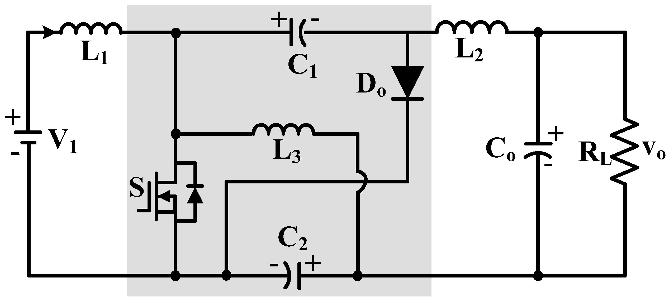
The developed Ćuk converter is depicted in Figure 1. A classical Ćuk converter was modified with an additional inductor (L3) and capacitor (C2). Figure 2a and b provides the equivalent circuit representation of the modified Ćuk converter with the semiconductor switch S turned ON and OFF, respectively.
When the switch S is turned ON and OFF, the following inductance voltage equations can be written to the circuit over one period for steady-state conditions. When the S is ON:
VL1 = V1, VL2 = Vo − VC2 − VC1, VL3 = − VC2
When the S is OFF:
VL1 = V1 − VC1, VL2 = − Vo + VC2, VL3 = VC1 + VC2
According to Faraday’s Law, the average voltage across an inductor is zero at steady-state. Hence, the voltage gain ratio of the converter can be obtained by starting the commonly used equation given below.
δ VL(ON) = (1 − δ)VL(OFF)
The term δ means the duty ratio of the switch S. Equation (3) will be written for L1, L2, and L3, and required voltage gain ratio equation will be obtained.
First, (3) is written for L1, and the equation given below is obtained;
δ V1 = (1 − δ)(V1 − VC)
The above Equation (4) can be simplified as:
(2 δ − 1)V1 = (δ − 1) VC1
Second, (3) can be written for L2 as given below:
δ (Vo − VC2 − VC1) = (1 − δ)(Vo + VC2)
Equation (6) can be arranged as given below:
Vo (2 δ − 1) = VC2 + δ VC1
Finally, (3) can be written for L3:
δVC2 = (1 − δ)(VC1 + VC2)
This simplifies to:
VC2 = (1 − δ)VC1
If (5), (7), and (9) are combined, the duty ratio of the converter can be obtained. If (9) is inserted into (7),
Vo (2 δ − 1) = VC1
If (10) is inserted into (5), the duty ratio of the system can be finalized.
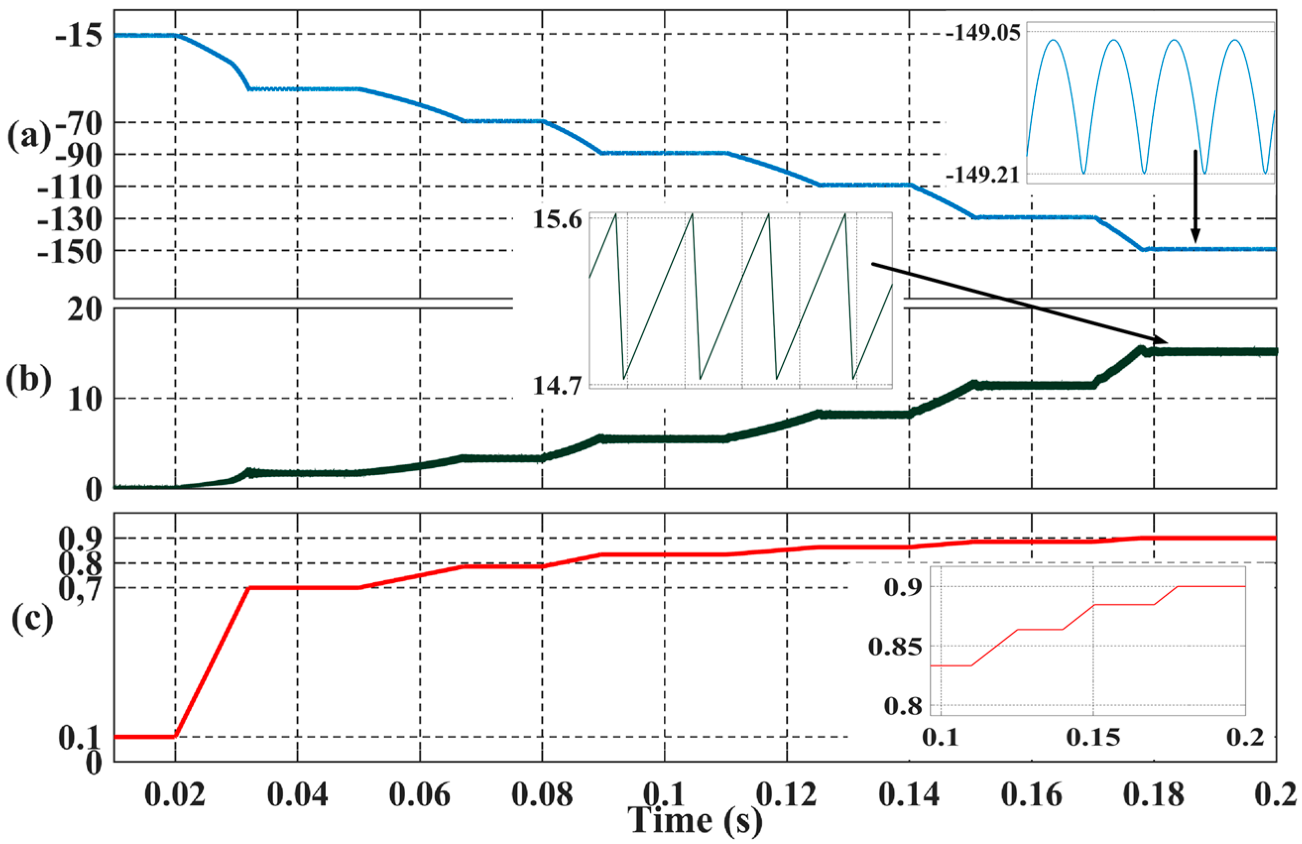
A sample design circuit can be conducted by using the circuit parameters given in Table 1 in MATLAB/Simulink. Different δ values are applied in the simulation, as shown in Figure 3c. Output voltage (Vo) and input current (ii) curves change accordingly, as shown in Figure 3a,b, respectively. Output voltage and input currents are zoomed; it is observed in simulations that the frequency of the ripples is equal to the SF (150 kHz).
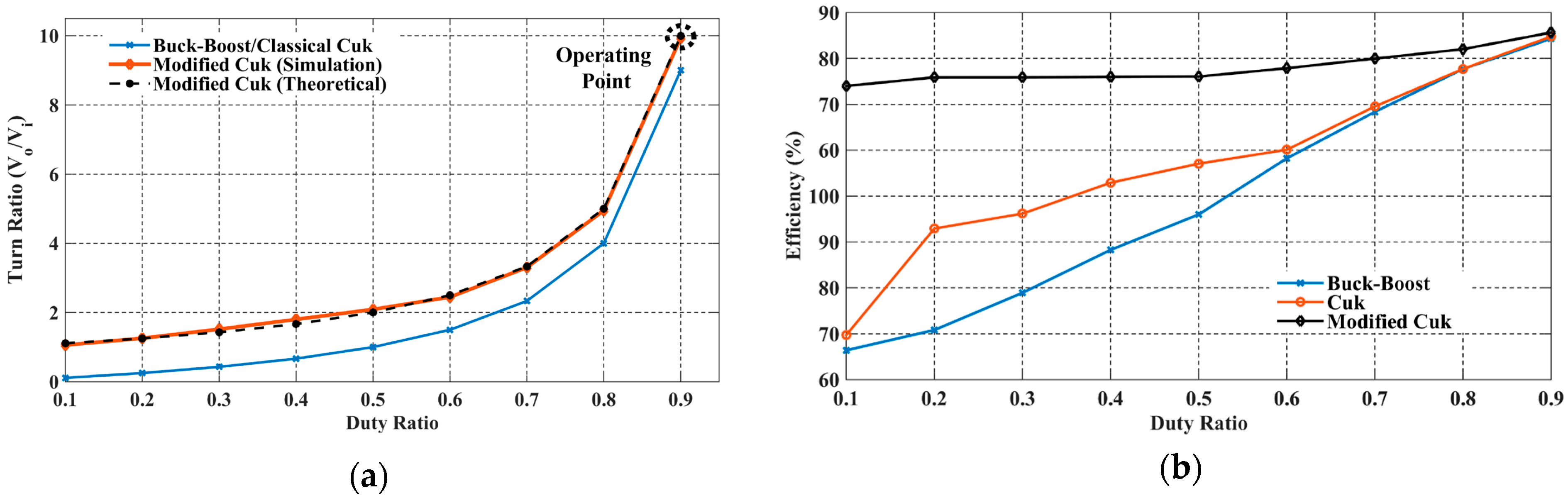
The performance of the modified Ćuk converter was compared to classical Ćuk and buck/boost converter circuits. Figure 4a shows δ comparison of converters. A simulation platform is constructed in MATLAB/Simulink with the same parameters given in Table 1. Theoretical and simulation values of the modified Ćuk converter validate the results. Efficiency comparison of simulated buck/boost, Ćuk, and modified Ćuk converter is depicted in Figure 4b. Modified Ćuk converter efficiency is higher than classical Ćuk and buck/boost converter. It can be stated that the proposed modified Ćuk converter produces higher efficiency due to the inclusion of additional passive elements. This reduces several parasitic effects and switching/conduction losses and increases voltage gain ratio, as emphasized in [37].
3. Equivalent Control of Modified Ćuk Converter
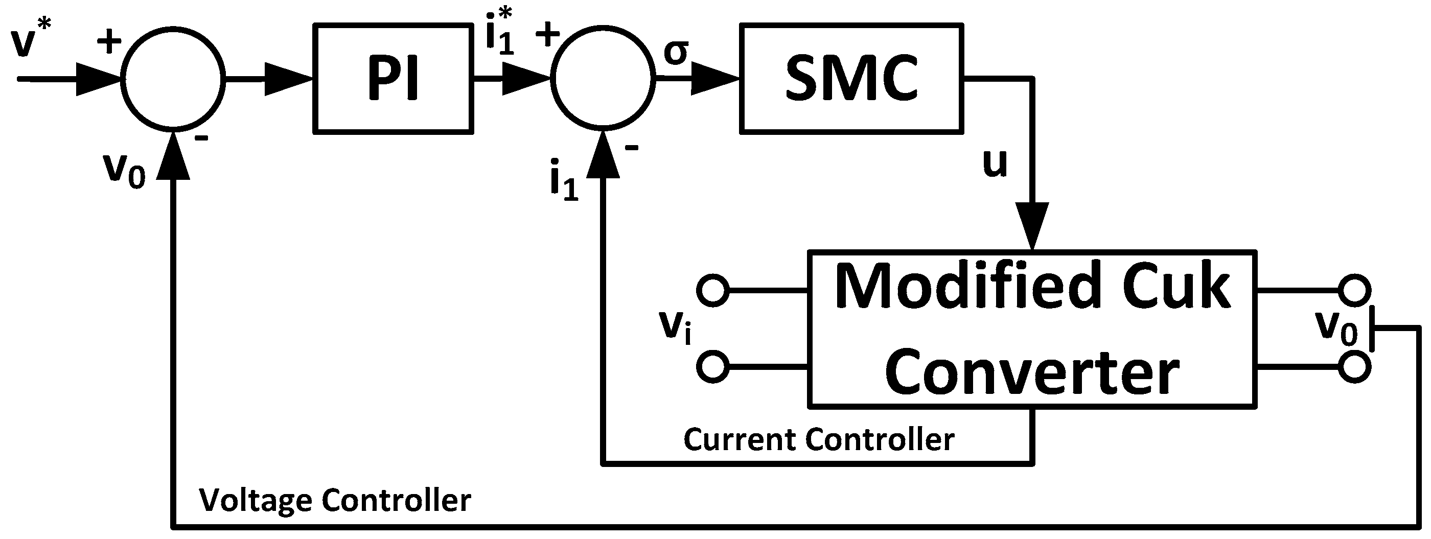
A cascaded PI+SMC controller structure could be used for ease of implementation to modified Ćuk converter as depicted in Figure 5. A simple external voltage controller can generate input current reference, while equivalent controller controls the input current [29,30].
Although the modified Ćuk converter is a third-order nonlinear model, only an input current equation is required to construct an equivalent controller. This is the main advantage of SMC-based equivalent controllers, since the performance is independent of all system dynamics and parameter variations. Input current of the modified Ćuk converter in terms of Kirchhoff’s voltage law can be written in the following form:
The terms Vi and Vc1 are input C1 voltages, and u is the switching signal of semiconductor switch as explained below.
The external PI controller aims to achieve the reference voltage target, and the output of the PI controller acts as reference current (i*). The internal SMC-based equivalent current controller aims to track current trajectory, and the analytical design procedure is detailed below. The switching surface can be given as [29,30]:
The time derivative of the switching surface is:
If the input current equation of the modified Ćuk converter in (12) is written to derivative of the switching surface in Equation (15), the following equation can be obtained:
If is assumed to be zero at steady-state, the equivalent control signal can be generated as given below.
The switching surface can be simplified as given below, considering is zero at steady-state. The continuous function ueq will be converted into discontinuous form as follows:
Closed loop control signal from switching surface can be given as:
The term K is positive definite control gain, and if (19) is inserted in (18), the switching surface can be written as follows:
where is the estimated equivalent control input. It can be written in steady-state that
Finally, stability and existing conditions for sliding mode control must be clarified [18]. The definition must be satisfied, and it can be derived from (21) that;
Thus, the stability of the sliding surface is satisfied. Controller structure can be constructed by estimating . Estimation of the equivalent control can be formed as:
Where the term l is the filter gain of the estimator. It is assumed that is constant, and the time derivative of (23) can be written as given below:
The time derivative of in (18) can be inserted into (23) as given below:
It can be stated that in steady state:
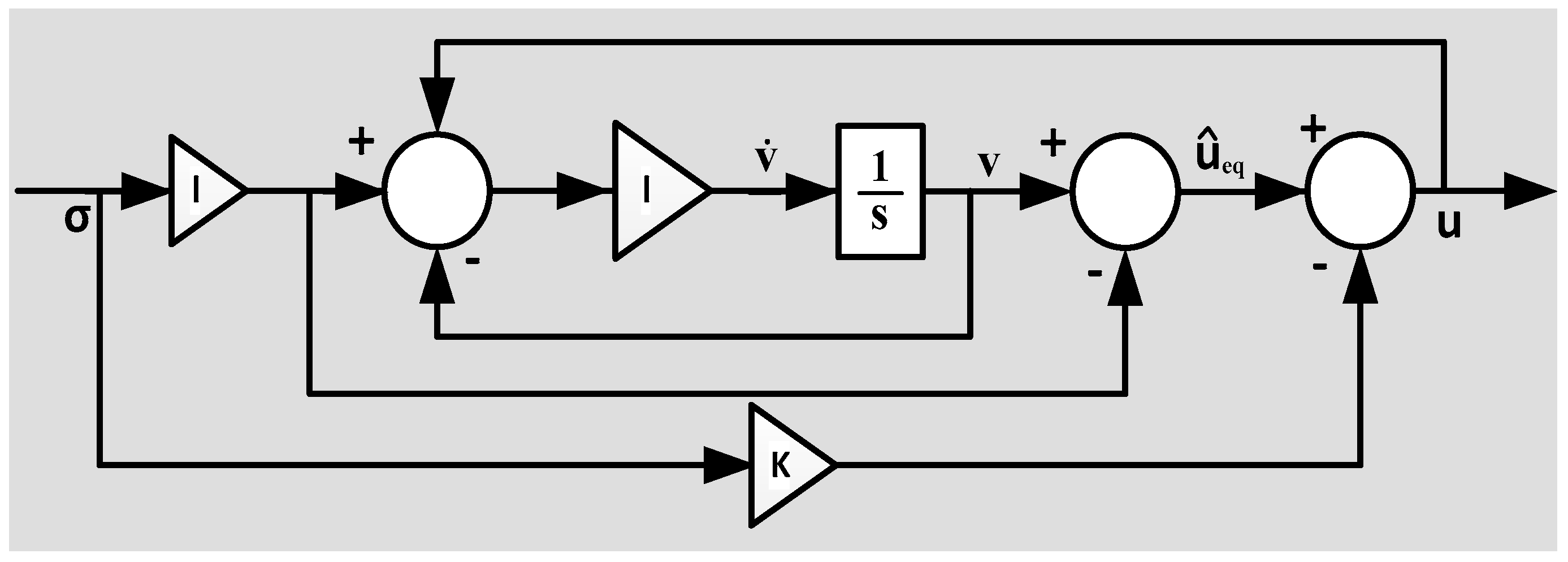
Finally, the simple equivalent controller structure in Figure 6 can be obtained from the definitions written above.
As detailed in [25,29,30], Figure 6 shows that a dynamic system can be formed as a series of integrators, and it can be assumed that the output of this system can be estimated by an upper bound of the integral. Finally, a dynamic relay with hysteresis function as given in Figure 7 can be applied to control a signal to generate a sliding surface which oscillates with the magnitude of M.
The main disadvantage of the SMC-based equivalent controller is variable switching frequency (SF), because the magnitude of oscillations in sliding surface is highly dependent on circuit parameters and operating conditions due to the nonlinear behavior of the converter. One of the methods that can constrain the sliding surface to constant SF operation can be a dynamic hysteresis controller [35] which dynamically changes the magnitude of sliding surface according to the desired switching frequency value. An additional PI controller which intermittently operates to bring back the SF to the desired value can be a simple and practical solution. The output of the PI controller dynamically changes the hysteresis of dynamic relay (M). Thus, SF can settle to a desired interval accordingly.
Another drawback of the method is the requirement of the SF measurement. A SF measurement algorithm could be implemented by counting the rising edge of the gate signals at certain instants. If the number of rising signals is divided into a predefined time interval, SF can be easily calculated. As a result, an intermittent PI controller structure can keep the SF constant at a specified interval as shown in Figure 8. The output of the intermittent PI controller is the resultant M value of the dynamic relay with hysteresis function.
4. Simulation Results
Four different scenarios are implemented in a single simulation in MATLAB/Simulink SimPowerSystem platform at different time instants. Variable Step Ode23tb (stiff/TR-BDF2) solver is used in simulations. Circuit parameters given in Table 1 are used in simulation. Stable gains for external PI controller and equivalent controller are given in Table 2.
Standard Routh–Hurwitz criterion for determination of PI gain values is omitted in this paper, and all gain values are determined using trial–error methods. For further details of Routh–Hurwitz criterion for external PI controllers, one can refer to [24]. The target SF value was selected as 150 kHz, and intermittent PI hysteresis controller was only enabled when the absolute value of error exceeded 10, as shown in Figure 8. It is not possible to realize a precise controller for SF control in all perturbations due to unexpected oscillations in M value.
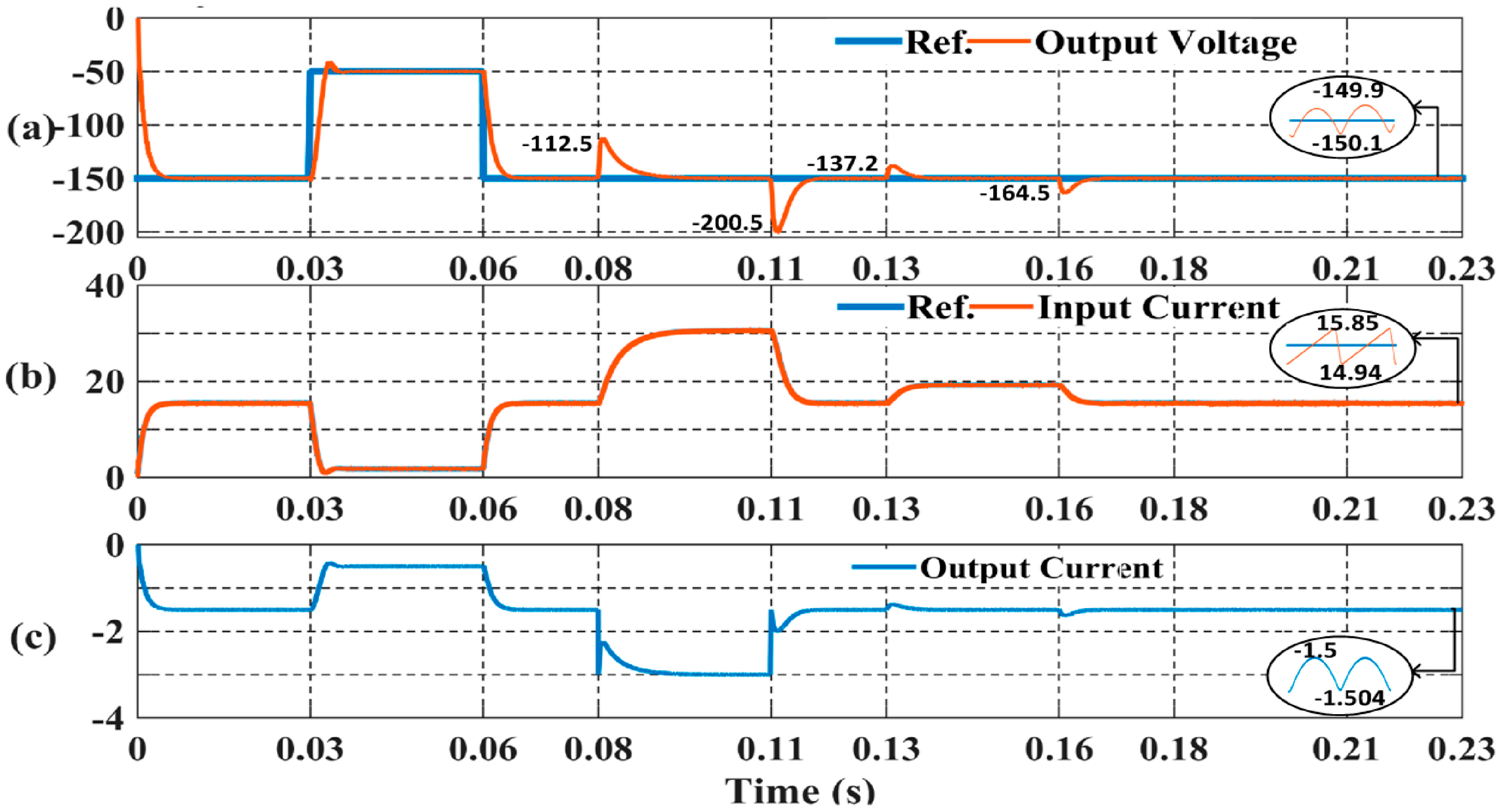
Applied step and disturbance instants are given below.
- 0.03–0.06 s: Output voltage reference is changed from −150 V to −50 V.
- 0.08–0.11 s: Load resistance is decreased from 100 Ω to 50 Ω (100% load increase)
- 0.13–0.16 s: Input voltage is decreased from 15 V to 12 V (20% input voltage dip)
- 0.18–0.21 s: Input inductor (L1) is decreased from 100 μH to 85 μH (15% L1 reduction)
Figure 9 shows the output voltage and input current response at different perturbations. Required trajectories are successfully tracked at all disturbances. Figure 9a shows the output voltage trajectory at all peak values at the instants of perturbations. The controller successfully passed all perturbations. Figure 9b,c shows the input and output currents of the converter. All ripple values are zoomed, and matches the design circuit results of Figure 3.
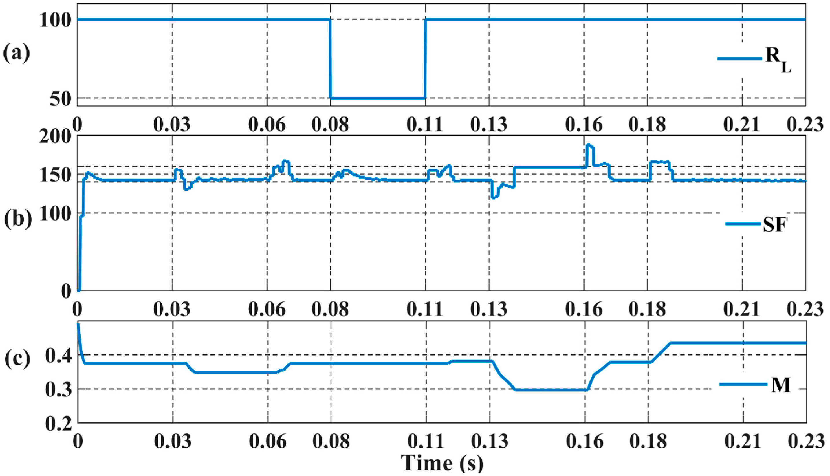
Figure 10 shows the performance of the intermittent hysteresis controller. Figure 10a shows the load resistance variation to validate the applied load variation. Figure 10b shows the SF variations at all perturbations. Target SF is achieved at all different perturbations by changing M value as shown in Figure 10c. SF exceeds the target value at transient conditions, but settles to target interval at all steady-state instants of perturbations. Figure 11 shows the output voltage and input current ripples at the instants of semiconductor ON and OFF states in simulation. Figure 11a shows the instants of the gate signal, and Figure 11b shows the control signal u generated by the SMC-based equivalent controller. Figure 11c,d show the ripple contents of output voltage and input current. The ripple values verify the ripple values at design circuit simulation in Figure 3.
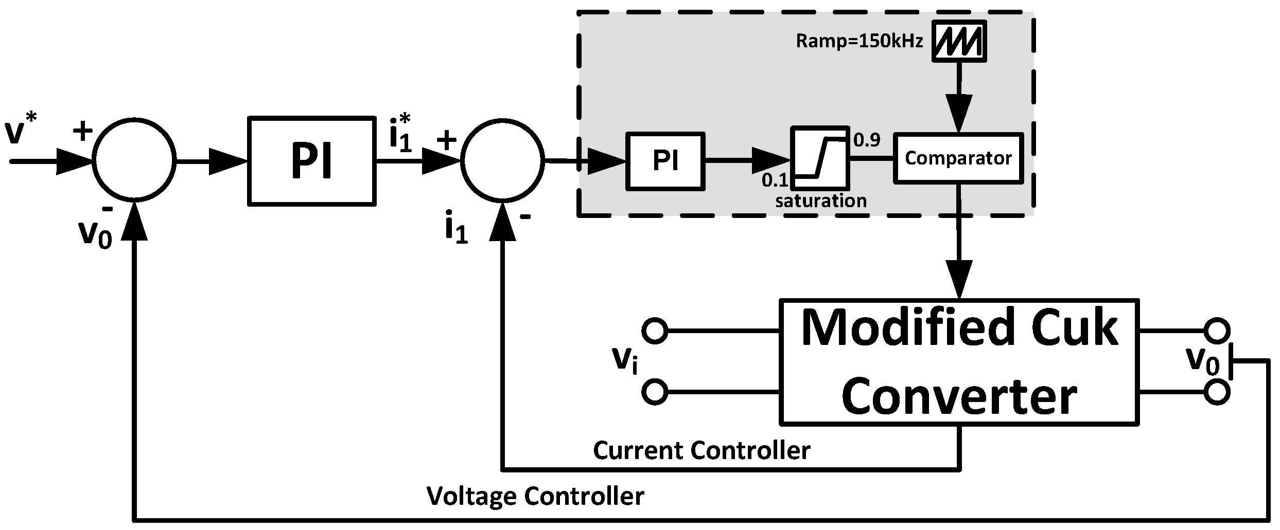
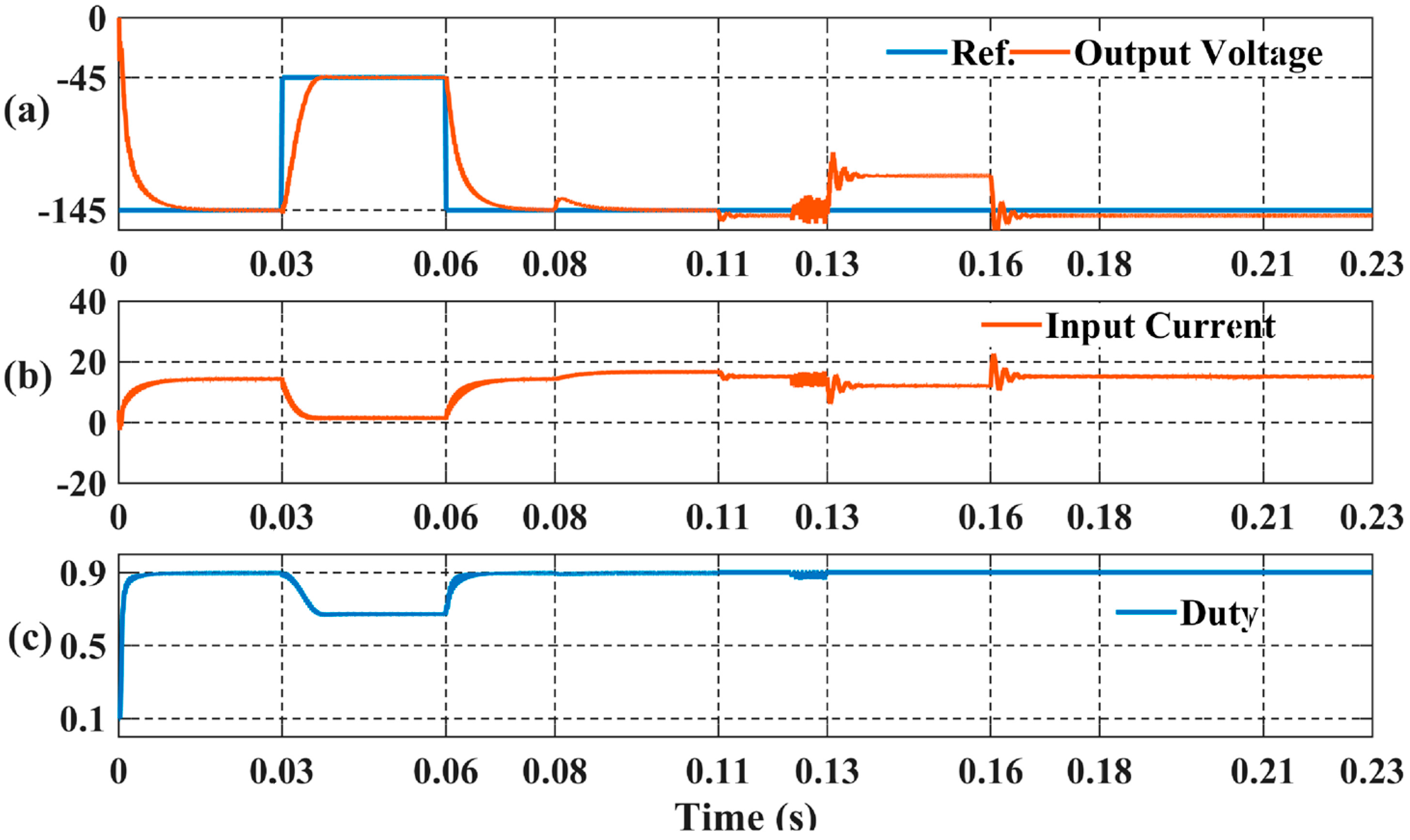
A comparison between classical linear control methods and the proposed equivalent controller was also attempted to show the effectiveness of proposed method. A cascaded controller structure which consists of voltage and current PI controllers is depicted in Figure 12. In particular, some studies use single voltage PI controllers to control a DC-DC converter. However, this type of controller has a very limited operational range, and comparison of a single PI controller would be inconsistent due to the cascaded controller structure of the proposed equivalent controller. An additional current controller introduces additional left half plane zeros to the controller and increases the performance of the controller structure. It is a difficult task to design a linear controller for a third-order modified Ćuk converter, and all states must be observed or measured. Perturbations applied to the controller are given below.
- 0.03–0.06 s: Output voltage reference is changed from −145 V to −45 V.
- 0.08–0.11 s: Load resistance is decreased from 100 Ω to 85 Ω (15% load increase)
- 0.13–0.16 s: Input voltage is decreased from 15 V to 12 V (20% input voltage dip)
- 0.18–0.21 s: Input inductor (L1) is decreased from 100 μH to 85 μH (15% L1 reduction)
Higher perturbations as applied to proposed SMC equivalent controller could not be accomplished due to stability problems. Maximum allowable δ is 0.9, and higher δ values could not be achieved. Therefore, −150 V output voltage reference could not be accomplished.
PI controller gain values are optimized with trial and error methods, which are given in Table 3. Controllers are tuned at maximum allowable proportional and integral coefficients to achieve the highest dynamic performance. Higher proportional and integral gains could not be achieved due to higher oscillations in voltage output.
Figure 12 shows the performance comparison of PI controller. Figure 12a shows that output voltage performance could not be achieved for all perturbations. Dynamic response is more sluggish compared to proposed SMC based equivalent controller, and load resistance change at 0.11th second causes steady state error and oscillations. Input voltage perturbation cannot be responded due to unavailability of higher δ than 0.9. Steady state error exists at the instant of input voltage perturbation due to sluggish dynamic performance and unavailability of higher δ. Figure 12b shows the responded input currents, and Figure 12c depicts the resultant δ.
Finally, performance indices of the proposed controller structure at PI controller. Figure 13a shows that output voltage performance could not be achieved for all perturbations. Dynamic response is more sluggish compared to the proposed SMC-based equivalent controller, and load resistance change at the 0.11th second causes steady-state error and oscillations. Input voltage perturbation cannot be responded due to the unavailability of higher δ than 0.9. Steady-state error exists at the instant of input voltage perturbation due to sluggish dynamic performance and unavailability of higher δ. Figure 13b shows the responded input currents, and Figure 13c depicts the resultant δ. All perturbations are summarized in Table 4. Maximum peak overshoots are outlined and it is shown that the controller passed high load impact values and other disturbances. The value of M is dynamically changed according to SF requirements at different conditions. Input current and output voltage ripples changed according to varying M value.
5. Conclusions
This paper proposed a modified high output gain Ćuk converter with an SMC-based equivalent controller. The efficiency and performance of a classical Ćuk converter was improved by the simple inclusion of a single inductor and capacitor. Moreover, a constant switching frequency cascaded equivalent controller structure is proposed. Simulation results show the effectiveness and robustness of the proposed method, and the constant switching frequency approach to the SMC-based controller provides the opportunity of simple application to real systems.
Acknowledgments
No source of funding for this project.
Author Contributions
All authors contributed and involved equally in framing the full version of the research article in its current form of decimation.
Conflicts of Interest
The authors declare no conflict of interest.
References
- Sanjeevikumar, P.; Grandi, G.; Wheeler, P.; Blaabjerg, F.; Loncarski, J. A simple mPPT algorithm for novel PV power generation system by high output voltage DC-DC boost Converter. In Proceedings of the 24th International Symposium on Industrial Electronics, Rio de Janeiro, Brazil, 3–5 June 2015; pp. 214–220. [Google Scholar]
- Mahajan, S.B.; Sanjeevikumar, P.; Blaabjerg, F. A Multistage DC-DC step-up self-balanced and magnetic component-free converter for photovoltaic application: Hardware implementation. Energies 2017, 10, 719. [Google Scholar]
- Mahajan, S.B.; Sanjeevikumar, P.; Blaabjerg, F.; Ojo, S.; Seshagiri, S.; Kulkarni, R. Inverting Nx and 2Nx non isolated multilevel boost converter for renewable energy application. In Proceedings of the 4th IET International Conference on Clean Energy and Technology, Kuala Lumpur, Malaysia, 14–15 November 2016; pp. 1–8. [Google Scholar]
- Sanjeevikumar, P.; Grandi, G.; Blaabjerg, F.; Wheeler, P.; Siano, P.; Hammami, M. A Comprehensive Analysis and Hardware Implementation of Control Strategies for High Output Voltage DC-DC Boost Power Converter. Int. J. Comput. Intell. Syst. 2017, 10, 140–152. [Google Scholar]
- Mahajan, S.B.; Sanjeevikumar, P.; Wheeler, P.; Blaabjerg, F.; Rivera, M.; Kulkarni, R. XY converter family: A new breed of buck boost converter for high step-up renewable energy applications. In Proceedings of the IEEE International Conference on Automatica, Curico, Chile, 19–21 October 2016; pp. 1–8. [Google Scholar]
- Bhaskar, M.S.; Sanjeevikumar, P.; Kulkarni, R.; Blaabjerg, F.; Seshagiri, S.; Hajizadeh, A. Novel LY converter topologies for high gain transfer ratio—A new breed of XY family. In Proceedings of the 4th IET International Conference on Clean Energy and Technology, Kuala Lumpur, Malaysia, 14–15 November 2016; pp. 4–8. [Google Scholar]
- Mahajan, S.B.; Kulkarni, R.; Sanjeevikumar, P.; Blaabjerg, F.; Fedák, V.; Cernat, M. Non-isolated and non-inverting Cockcroft Walton multiplier based hybrid 2Nx interleaved boost converter for renewable energy applications. In Proceedings of the IEEE Conference on 17th The Power Electronics and Motion Control, Varna, Bulgaria, 25–28 September 2016; pp. 146–151. [Google Scholar]
- Mahajan, S.B.; Kulkarni, R.; Sanjeevikumar, P.; Siano, P.; Blaabjerg, F. Hybrid Non-isolated and non-inverting Nx interleaved DC-DC multilevel boost converter for renewable energy applications. In Proceedings of the 16th IEEE International Conference on Environment and Electrical Engineering, Florence, Italy, 7–10 June 2016; pp. 1–6. [Google Scholar]
- Sanjeevikumar, P.; Kabalci, E.; Iqbal, A.; Abu-Rub, H.; Ojo, O. Control strategy and hardware implementation for DC-DC boost power conversion based on proportional-integral compensator for high voltage application. Eng. Sci. Tech. Int. J. 2014, 18, 163–170. [Google Scholar]
- Li, C.W.; He, X. Review of non-isolated high step-up DC/DC converters in photovoltaic grid-connected applications. IEEE Trans. Ind. Electron. 2011, 58, 1239–1250. [Google Scholar] [CrossRef]
- Costantino, N.; Serventi, R.; Tinfena, F.; D’Abramo, P.; Chassard, P.; Tisserand, P.; Fanucci, L. Design and test of an HV-CMOS intelligent power switch with integrated protections and self-diagnostic for harsh automotive applications. IEEE Trans. Ind. Electron. 2011, 58, 2715–2727. [Google Scholar] [CrossRef]
- Saponara, S.; Pasetti, G.; Tinfena, F.; Fanucci, L.; D’Abramo, P. HV-CMOS design and characterization of a smart rotor coil driver for automotive alternators. IEEE Trans. Ind. Electron. 2013, 60, 2309–2317. [Google Scholar] [CrossRef]
- Baronti, F.; Lazzeri, A.; Roncella, R.; Saletti, R.; Saponara, S. Design and characterization of a robotized gearbox system based on voice coil actuators for a Formula SAE Race Car. IEEE/ASME Trans. Mechatron. 2013, 18, 53–61. [Google Scholar] [CrossRef]
- Saponara, S.; Fanucci, L.; Bernardo, F.; Falciani, A. Predictive diagnosis of high-power transformer faults by networking vibration measuring nodes with integrated signal processing. IEEE Trans. Inst. Meas. 2016, 65, 1749–1760. [Google Scholar] [CrossRef]
- Zhu, M.; Luo, F.L. Enhanced self-lift Ćuk converter for negative to positive voltage conversion. IEEE Trans. Power Electron. 2010, 25, 2227–2233. [Google Scholar] [CrossRef]
- Sabzali, A.J.; Ismail, E.H.; Al-Saffar, M.A.; Fardoun, A.A. New bridgeless DCM Sepic and Ćuk PFC rectifiers with low conduction and switching losses. IEEE Trans. Ind. Appl. 2011, 47, 873–881. [Google Scholar] [CrossRef]
- Ćuk, S.; Middlebrook, R.D. Advances in switched-mode power conversion part I. IEEE Trans. Ind. Electron. 1983, 1, 10–19. [Google Scholar] [CrossRef]
- Ćuk, S.; Middlebrook, R.D. Advances in switched-mode power conversion part II. IEEE Trans. Ind. Electron. 1983, 1, 19–29. [Google Scholar] [CrossRef]
- Rashid, M.H. Power Electronics Handbook: Circuits, Devices and Applications; Elsevier: New York, NY, USA, 2010; pp. 249–265. [Google Scholar]
- Flores, J.L.; Avalos, J.; Espinoza, C.A.B. Passivity-based controller and online algebraic estimation of the load parameter of the DC-to-DC power converter Ćuk type. IEEE Lat. Am. Trans. 2011, 9, 50–57. [Google Scholar] [CrossRef]
- Mahdavi, J.; Nasiri, M.R.; Agah, A.; Emadi, A. Application of neural networks and state-space averaging to DC/DC PWM converters in sliding mode operation. IEEE/ASME Trans. Mechatron. 2005, 10, 60–67. [Google Scholar] [CrossRef]
- Safari, A.; Mekhilef, S. Simulation and hardware implementation of incremental conductance MPPT with direct control method using Ćuk converter. IEEE Trans. Ind. Electron. 2011, 58, 1154–1161. [Google Scholar] [CrossRef]
- Balestrino, A.; Landi, A.; Sani, L. Ćuk converter global control via fuzzy logic and scaling factors. IEEE Trans. Ind. Appl. 2002, 38, 406–413. [Google Scholar] [CrossRef]
- Chen, Z. PI and sliding mode control of a Ćuk converter. IEEE Trans. Power Electron. 2012, 27, 3695–3703. [Google Scholar] [CrossRef]
- Utkin, V.; Guldner, J.; Jingxin, S. Sliding Mode Control in Electro-Mechanical Systems; CRC Press: Boca Raton, USA, 2009; pp. 325–355. [Google Scholar]
- Venkataramanan, R.; Sabanovic, A.; Ćuk, S. Sliding mode control of DC–DC converters. In Proceedings of the 2012 IEEE 51st Annual Conference on Decision and Control, Maui, HI, USA, 10–13 December 2012. [Google Scholar]
- Venkataramanan, R. Sliding Mode Control of Power Converters. Ph.D. Thesis, California Institute of Technology, Pasadena, CA, USA, 1986. [Google Scholar]
- Tan, S.C.; Lai, Y.M.; Chi, K.T. General design issues of sliding-mode controllers in DC-DC converters. IEEE Trans. Power Electron. 2008, 55, 1160–1174. [Google Scholar]
- Ahmad, F.; Rasool, A.; Ozsoy, E.E.; Sabanovic, A.; Elitas, M. A robust cascaded controller for DC-DC boost and Ćuk converters. World J. Eng. 2017, 14. [Google Scholar] [CrossRef]
- Ahmad, F.; Rasool, A.; Ozsoy, E.E.; Sabanovic, A.; Elitas, M. Design of a robust cascaded controller for Cuk converter. In Proceedings of the IEEE International Power Electronics and Motion Control Conference, Varna, Bulgaria, 25–28 September 2016; pp. 80–85. [Google Scholar]
- Cardoso, B.J.; Moreira, A.F.; Menezes, B.R.; Cortizo, P.C. Analysis of switching frequency reduction methods applied to sliding mode controlled DC-DC converters. In Proceedings of the 7th Annual Applied Power Electronics Conference and Exposition, Boston, MA, USA, 23–27 February 1992; pp. 403–410. [Google Scholar]
- He, Y.; Luo, F.L. Sliding-mode control for dc–dc converters with constant switching frequency. IEEE Proc. Control Theory Appl. 2006, 153, 37–45. [Google Scholar] [CrossRef]
- Agostinelli, M.; Priewasser, R.; Marsili, S.; Huemer, M. Constant switching frequency techniques for sliding mode control in DC-DC converters. In Proceedings of the 2011 Joint 3rd Int’l Workshop on Nonlinear Dynamics and Synchronization (INDS) & 16th Int’l Symposium on Theoretical Electrical Engineering (ISTET), Klagenfurt, Austria, 25–27 July 2011; pp. 1–5. [Google Scholar]
- Tan, S.C.; Lai, Y.M.; Tse, C.K.; Cheung, M.K. A fixed-frequency pulse width modulation based quasi-sliding-mode controller for buck converters. IEEE Trans. Power Electron. 2005, 20, 1379–1392. [Google Scholar] [CrossRef]
- Leung, K.K.S.; Chung, H.S.H. Dynamic hysteresis band control of the buck converter with fast transient response. IEEE Trans. Circuits Syst. II Expr. Briefs 2015, 52, 398–402. [Google Scholar] [CrossRef]
- Ho, C.N.M.; Cheung, V.S.; Chung, H.S.H. Constant-frequency hysteresis current control of grid-connected VSI without bandwidth control. IEEE Trans. Power Electron. 2009, 24, 2484–2495. [Google Scholar] [CrossRef]
- Park, S.H.; Park, S.R.; Yu, J.S.; Jung, Y.C.; Won, C.Y. Analysis and design of a soft-switching boost converter with an HI-Bridge auxiliary resonant circuit. IEEE Trans. Power Electron. 2010, 25, 2142–2149. [Google Scholar] [CrossRef]
Figure 1.
Topology of proposed novel Ćuk converter.

Figure 2.
Circuit configuration (a) ON state; (b) OFF state.
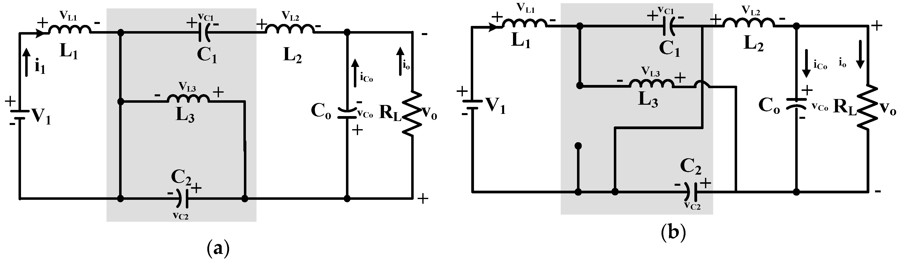
Figure 3.
Simulation of modified Ćuk converter. (a) Output Voltage (V); (b) Input Current (A); (c) δ.
Figure 3.
Simulation of modified Ćuk converter. (a) Output Voltage (V); (b) Input Current (A); (c) δ.

Figure 4.
Comparison of buck/boost, Ćuk, and modified Ćuk converter. (a) Duty Ratio; (b) Efficiency.
Figure 4.
Comparison of buck/boost, Ćuk, and modified Ćuk converter. (a) Duty Ratio; (b) Efficiency.

Figure 5.
Cascaded control of modified Ćuk converter. PI: proportional integral; SMC: sliding mode controller.
Figure 5.
Cascaded control of modified Ćuk converter. PI: proportional integral; SMC: sliding mode controller.

Figure 6.
SMC-based equivalent controller.

Figure 7.
Dynamic relay with hysteresis function.
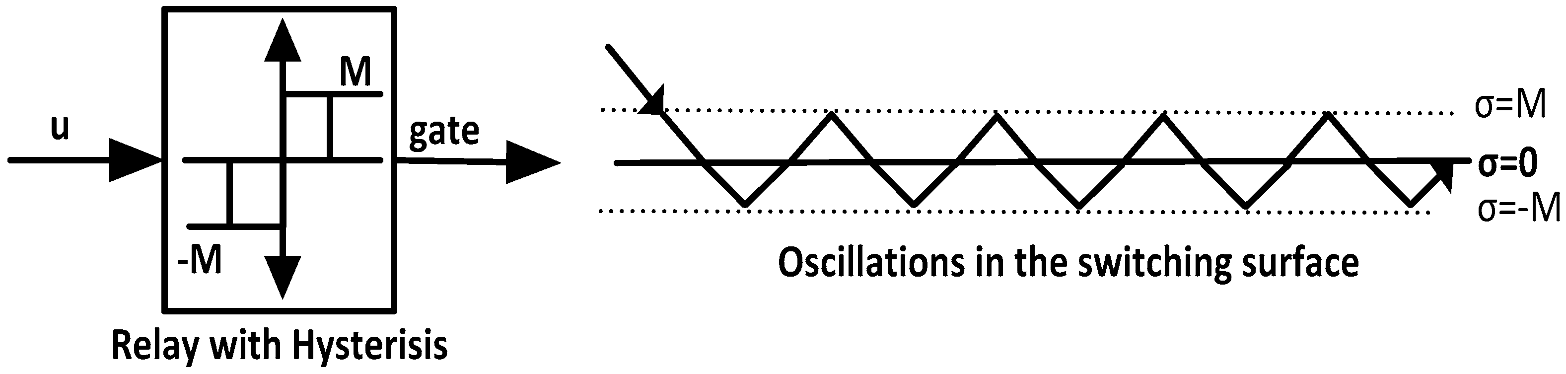
Figure 8.
Switching frequency (SF) measurement and intermittent PI controller.
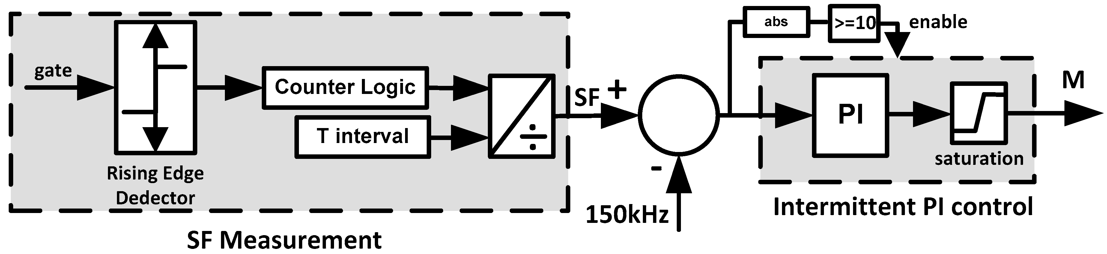
Figure 9.
Performance of proposed equivalent controller. (a) Output Voltage (V); (b) Input Current (A); (c) Output Current (A).
Figure 9.
Performance of proposed equivalent controller. (a) Output Voltage (V); (b) Input Current (A); (c) Output Current (A).

Figure 10.
Performance of the proposed equivalent controller. (a) RL; (b) SF; (c) M.

Figure 11.
Output voltage and current ripple transients. (a) Gate Signal; (b) Control Signal (u); (c) Input current; (d) Output voltage (Vo).
Figure 11.
Output voltage and current ripple transients. (a) Gate Signal; (b) Control Signal (u); (c) Input current; (d) Output voltage (Vo).
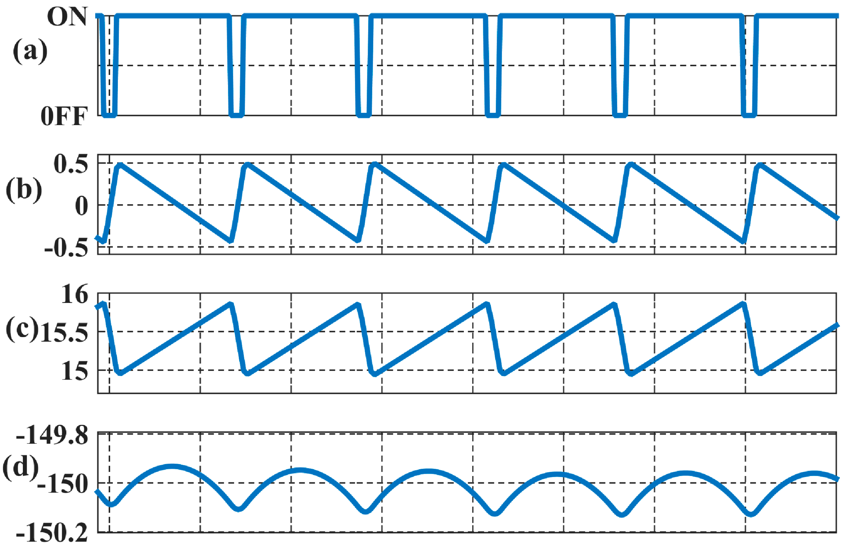
Figure 12.
Comparison controller structure.

Figure 13.
Comparison controller performance. (a) Output voltage; (b) Input current (u); (c) δ.


Table 1.
Design parameters of Modified Ćuk Converter.
| Symbol | Quantity | Unit |
|---|---|---|
| Input Voltage | 15 | V |
| Duty Ratio (∆) | 0.1–0.9 | – |
| Switching Frequency | 150 | kHz |
| Inductances (L1, L2, L3) | 100 | μH |
| Capacitors (C0, C1, C2) | 5 | μF |
| Load Resistance | 100 | Ω |
Table 2.
Controller parameters of modified Ćuk converter.
| Symbol | Quantity |
|---|---|
| Kp of voltage PI controller | 0.001 |
| KI of PI voltage controller | 90 |
| Target switching frequency | 140–160 kHz |
| K of equivalent controller | 0.01 |
| L of equivalent controller | 1 |
| Kp of hysteresis controller | 0.00005 |
| KI of hysteresis controller | 0.6 |
Table 3.
Controller parameters of comparison PI controller.
| Symbol | Quantity |
|---|---|
| Kp of PI voltage controller | 0.001 |
| KI of PI voltage controller | 50 |
| Kp of PI current controller | 0.001 |
| KI of PI current controller | 500 |
| Switching Frequency | 150 kHz |
Table 4.
Performance indices of modified Ćuk converter.
| Perturbation | Vo Peak Overshoot | M | ii Ripple (A) | Vo Ripple (V) |
|---|---|---|---|---|
| Steady State (No Perturbation) | N/A | 0.3750 | 0.9 | 0.15 |
| 0.03 s: Vo −150 to −50 V | 5.2 V | 0.3476 | 0.7 | 0.14 |
| 0.06 s: Vo −150 to −50 V | 0 | |||
| 0.08 s: RL 100 to 50 Ω | 37.5 V | 0.3748 | 0.9 | 0.17 |
| 0.11 s: RL 50 to 100 Ω | 50.5 V | |||
| 0.13 s: Vi 15 to 12 V | 12.8 V | 0.297 | 0.6 | 0.12 |
| 0.16 s: Vi 12 to 15 V | 14.5 V | |||
| 0.18 s: L1 100 to 85 μH | 0 | 0.435 | 1.8 | 0.16 |
| 0.21 s: L1 85 to 100 μH | 0 |
© 2017 by the authors. Licensee MDPI, Basel, Switzerland. This article is an open access article distributed under the terms and conditions of the Creative Commons Attribution (CC BY) license (http://creativecommons.org/licenses/by/4.0/).
Share and Cite
MDPI and ACS Style
Padmanaban, S.; Ozsoy, E.; Fedák, V.; Blaabjerg, F. Development of Sliding Mode Controller for a Modified Boost Ćuk Converter Configuration. Energies 2017, 10, 1513. https://doi.org/10.3390/en10101513
AMA Style
Padmanaban S, Ozsoy E, Fedák V, Blaabjerg F. Development of Sliding Mode Controller for a Modified Boost Ćuk Converter Configuration. Energies. 2017; 10(10):1513. https://doi.org/10.3390/en10101513
Chicago/Turabian StylePadmanaban, Sanjeevikumar, Emre Ozsoy, Viliam Fedák, and Frede Blaabjerg. 2017. "Development of Sliding Mode Controller for a Modified Boost Ćuk Converter Configuration" Energies 10, no. 10: 1513. https://doi.org/10.3390/en10101513
Note that from the first issue of 2016, this journal uses article numbers instead of page numbers. See further details here.