Modeling and Static Analysis of Primary Consequent-Pole Tubular Transverse-Flux Flux-Reversal Linear Machine

1
College of Automation Engineering, Nanjing University of Aeronautics and Astronautics, Nanjing 211106, Jiangsu, China
2
ESTUN AUTOMATION TECHNOLOGY Co., LTD, Nanjing 211106, Jiangsu, China
*
Authors to whom correspondence should be addressed.
Energies 2017, 10(10), 1479; https://doi.org/10.3390/en10101479
Submission received: 4 August 2017
/
Revised: 15 September 2017
/
Accepted: 18 September 2017
/
Published: 24 September 2017
(This article belongs to the Special Issue Emerging Power Electronics Technologies for Power Systems and Machine Drives)
Abstract
:A novel primary consequent-pole tubular transverse-flux flux-reversal linear machine (TTFFRLM) is proposed in this paper. The permanent magnets (PMs) of the machine are located on the inner surface of the short teeth of the primary iron cores for reducing the amount of PM in long stroke drive systems, and the primary is easily manufactured. The structure and principle of this machine are analyzed in detail. Based on the unit machine, a no-load equivalent magnetic circuit model is established by using the magnetic circuit method. Then, the equations of the no-load back electromotive force (back-EMF) and the electromagnetic thrust force are deduced. The simulation models of the unit machine are established by equivalent 2D finite element method (FEM) for saving computation time, and the static characteristics, including the flux field, the no-load back-EMF, and the electromagnetic thrust force, are analyzed. Detailed simulation and experimental results of a three-phase 4-poles 12-slots machine are given. The results verify the correctness and effectiveness of topology, model, and analysis method of the proposed TTFFRLM. Compared with the conventional TTFFRLM, the proposed prototype has the advantages of a lower cost and smaller electromagnetic thrust force ripple.
1. Introduction
Permanent magnet linear machine (PMLM), which has the advantages of the high thrust density, high positioning accuracy, high response speed, low noise, low maintenance, and simple structure, is widely used in direct drive systems [1,2,3,4,5,6].
According to different mounting positions of permanent magnets (PM), the PMLM can be divided into the primary PM type and the secondary PM type. For the secondary PM type, the PMs have a disadvantage of heat dissipation due to the presence of induced eddy current. Therefore, the PMs are prone to irreversible demagnetization at a high ambient temperature. Furthermore, the machine used in the long stroke drive systems has a problem of high cost, thus engineering applications and popularization are limited [7]. For the primary PM type PMLM, armature winding and PMs are both located in the primary, and the secondary is only composed of magnetic iron cores. Thus, the above shortages can be overcame [8,9,10].
The PMLM can be divided into single-sided plate type, double-sided plate type, and tubular type according to different structures of primary and secondary. In the above topologies, the tubular PMLM has no transverse end effect and no unilateral magnetic pull. Therefore, it has been widely used in direct drive systems [11,12].
The primary PM tubular linear machine combines the advantages of primary PM type PMLM and tubular PMLM, hence, it has gotten more attention [13,14,15,16,17,18,19]. According to different mounting positions of PM on the primary iron core, the topologies of the primary PM tubular linear machine can be divided into: flux switching tubular linear machine (FSTLM), primary PM tubular vernier linear machine (PPMTVLM) and flux reversal tubular linear machine (FRTLM). The FSTLM is a combination of switched reluctance (SR) machine and PM machine. The secondary is simple and robust. However, the axially PMs are sandwiched between stator core modules, which is composed of soft magnetic composite (SMC) material, and the armature winding with a pan-cake structure is embedded in stator core modules. Therefore, the primary manufacturing process is relatively complex. In addition, the utilization rate of stator core modules is low because of the unipolar flux linkage in the armature winding, and the no-load back-EMF is asymmetrical [13]. Furthermore, in order to solve the problems of the unbalanced magnetic circuit in the end armature winding and bigger detent force of the FSTLM, the flux barrier is adopted in the primary, and the complexity of the primary structure is also increased [14]. When compared with the FSTLM, the PMs of the PPMTVLM are mounted on the primary iron core tooth surface, therefore, the PM fixing process is relatively simple. Based on the magnetic gearing principle, the force density is improved by increasing the number of PM poles. However, the armature winding is also a pan-cake structure. The tooth and yoke of the primary iron core are axially distributed alternately, which cannot be shaped by pressing die at once with silicon steel sheet. Therefore, the manufacturing of the armature winding and the primary iron core are also complex [15,16,17]. In order to simplify the manufacturing process of the primary in the conventional PM tubular linear machine, the FRTLM is investigated [18,19]. The primary iron core of the FRTLM is made of silicon steel sheet, and the tooth and yoke can be shaped by pressing die at once with silicon steel sheet. The armature winding adopts a concentrated winding structure. The PMs are mounted on the tooth surface of the primary iron core. Hence, the primary is easily manufactured. However, the PMs in the primary are not a consequent-pole distribution, the amount of PM is relatively large. In addition, the machine, which is a single-phase machine with a problem of self-starting, is not suitable for long stroke drive systems.
In this paper, a novel primary consequent-pole tubular transverse-flux flux-reversal linear machine (TTFFRLM) for long stroke drive systems is proposed. Based on the method of circumferential and axial dislocation distribution of secondary iron core units, the topologies of two-phase, three-phase, and multi-phase machines are realized. The PMs with consequent-pole distribution in the axis direction are located on the primary iron core tooth surface, hence the cost for long stroke drive systems can be reduced. The tooth and yoke of the primary iron core unit can be shaped by pressing die at once with the silicon steel sheet. The armature winding adopts a concentrated winding structure. Therefore, the manufacturing process of the primary is rather simple. When compared with conventional TTFFRLM, the proposed prototype has the advantages of less PM consumption and a smaller thrust force ripple.
This paper is organized as follows: in Section 2, the structure features and the working principle are described. In Section 3, a no-load equivalent magnetic circuit model is established by the magnetic circuit method. The equations of the no-load back-EMF and the electromagnetic thrust force are, respectively, deduced. In Section 4, based on the equivalent 2D FEM of the unit machine, the static characteristics are further studied, and some comparisons between the primary consequent-pole TTFFRLM topology and conventional TTFFRLM are made as well. In Section 5, experimental results from a three-phase 4-poles 12-slots TTFFRLM are given. Finally, conclusions are drawn in Section 6.
2. Structure and Principle
2.1. Structure of the Primary Consequent-Pole TTFFRLM
Figure 1a shows the structure diagram of the conventional TFFRLM. As shown, the armature winding and PMs are both placed on the primary [20]. The primary iron core tooth surface is all covered by PMs, therefore, the amount of PM is relatively large. In order to further reduce the amount of the primary PM, based on the conventional TFFRLM, the primary consequent-pole TFFRLM is proposed, as shown in Figure 1b. The PMs of the S pole have changed into a part of the primary iron core, thus the primary iron core tooth surface only has the PMs of the N pole, which are the consequent-pole distributed in axis direction. Furthermore, based on the primary consequent-pole TFFRLM, a novel primary consequent-pole TTFFRLM is designed and investigated. Figure 1c–f, show the structure diagram of the three-phase primary consequent-pole TTFFRLM, including the primary, the secondary, the sketch of evolution of primary iron core unit, and the primary iron core of the unit machine.
As shown in Figure 1c, the primary is composed of nm (m is the phase number of machine, and m ≥ 2; n is a natural number representing unit machine number of each phase) primaries of the unit machine. The primary of the unit machine consists of primary iron core units, armature winding, and PMs. As shown in Figure 1e, in order to achieve the primary iron core unit of the primary consequent-pole TFFRLM, the S pole PM in the primary iron core unit of the conventional TFFRLM is removed. The length of the tooth corresponding to the S pole PM is extended. The extended tooth is called the long tooth, and the tooth corresponding to the N pole PM is called the short tooth. The length ltl of the long tooth is equal to the sum of the length lts of the short tooth, and the thickness hpm of the N pole PM. The primary iron core unit is made of silicon steel sheet, and the tooth and yoke of the primary iron core unit can be shaped by pressing die at once with silicon steel sheet. The primary iron core of the unit machine is laminated by 2p (p is the pole pairs of the machine) primary iron core units in accordance with the long and short teeth alternately, and then the number of the primary iron core units is 2pnm. The armature winding of the unit machine is composed of two coils, respectively, wound on the long tooth and the short tooth, thus the number of the coils in the machine is 2nm. The PMs are arranged on the inner surface of the short tooth of the primary iron core units, then the number of the PMs is the same as the primary iron core units. The PMs have the same polarity (all of the N poles or all of the S poles, this paper selects N pole type), and the magnetization direction of the PMs is radial. The secondary is composed of the secondary iron core units, which are made of silicon steel sheet as well, and the nm columns secondary iron core units are distributed in circumferential direction. An axial groove is arranged on the outer surface of each secondary iron core unit. The groove is aligned with the notch of the primary iron core unit. The large circumferential direction detent force between the secondary and the primary would be produced, which can limit the relative circumferential rotation motion between the secondary and the primary.
The circumferential distribution of the secondary iron core units adopt a continuous ladder structure. The m columns correspond to a group. The n groups are set along the circumference, and there are nm columns secondary iron core units in circumferential direction.
Taking m = 3 and n = 2 for example, Figure 2 shows the circumferential outspread diagram of the secondary. The L is the axial length of the primary iron core unit. The axial center lines ladder spacing of the m columns secondary iron core units is La = L/mp.
2.2. Working Principle and Topology Structure of the Primary PM Consequent-Pole TTFFRLM
Considering the unilateral magnetic pull, the manufacturability, and the universality of the three-phase machine in engineering application, this paper takes a three-phase 4-poles 12-slots machine as an example, the working principle and topology of the continuous ladder type primary PM consequent-pole TTFFRLM are analyzed.
Figure 3 shows the outspread diagram of the machine topology. As shown, A phase consists of two groups of coils A1 and A2; B phase consists of two groups of coils B1 and B2; C phase consists of two groups of coils C1 and C2. The subscript “1” represents that the coil is wound around the teeth in a clockwise direction. The subscript “2” represents that the coil is wound around the teeth in a counterclockwise direction. Two coils of the primary of unit machine are connected in series, and the coils between two unit machines corresponding to any phase can be connected in series or in parallel. The axial length of PM is τ (pole pitch). In the axial direction, the PMs are alternately distributed by a single N pole type. In the circumferential direction, the PMs are alternately distributed by dual N poles type or by single N pole type, as shown in Figure 3 and Figure 1a, respectively. However, the arrangement of single N pole type PMs will cause leakage between the adjacent primary of the unit machines, and reduce the utilization ratio of PMs. Therefore, the arrangement PMs dual N poles type is adopted in this paper, and the magnetic circuit between the adjacent primary of the unit machines is independent of each other. The secondary is composed of two groups of secondary iron core units. In each group, the three columns of secondary iron core units are corresponding, respectively, to A phase, B phase, and C phase, in the circumferential direction. The ladder spacing of the axial center lines of the secondary iron core units of the three columns is La = 2τ/3. The axial distance between the axial center lines of each column adjacent secondary iron core units is 2τ.
When the secondary moves along the axial direction by movement velocity v, because of the alternating distribution of PMs, an alternating flux linkage that is perpendicular to the direction of motion is generated in the primary iron cores, therefore, the machine has the same characteristics with transverse-flux machine [20]. As shown in Figure 4, the working principle of A phase is given. When the axial center lines of the secondary iron core units are aligned with the axial center lines of the N pole corresponding to the coil A2, the flux linkage is maximum and the direction is counterclockwise, as shown in Figure 4a. When the axial center lines of the secondary iron core units are aligned with the axial center lines of the N pole corresponding to the coil A1, the flux linkage is maximum and the direction is clockwise, as shown in Figure 4c. When the secondary is in the position of b or d, the flux linkage is zero, as shown in Figure 4b,d. When the secondary is moving between the above four positions, the flux linkage ψpm and back-EMF e are alternating, as shown in Figure 4e,f, indicating that the primary iron core is better used [18]. When the axial distance between the axial center lines of the adjacent secondary iron core units is 2τ/3, the phase position difference of the three-phase back-EMF is 120 electrical degrees. The magnitude of the three-phase back-EMF is the same, and the frequency is f = v/2τ. When the three-phase alternating current with the same amplitude and phase position difference of 120 electrical degrees are fed into the three-phase symmetrical armature winding, if the secondary is fixed, the primary will move along the axial direction according to the principle of least resistance.
To sum up, for the three-phase 4-poles 12-slots primary PM consequent-pole TTFFRLM, the optimal topology has the following characteristics, the axial direction distribution of the PMs is the alternating distribution of single N pole type, the secondary is suitable for the continuous ladder structure, and the machine can be simplified as a unit machine for analysis. The following sections of this paper will do further research on this topology and unit machine.
3. Mathematical Model Analysis based on Magnetic Circuit Method
3.1. Equivalent Magnetic Circuit Model of the Unit Machine and No-Load Back-EMF
Figure 5 shows the structure of the unit machine of the three-phase 4-poles 12-slots primary PM consequent-pole TTFFRLM. As shown, considering the circumferential and axial magnetic flux leakage, the equivalent magnetic circuit model of the unit machine is given, as shown in Figure 6, Fm and Rm are the equivalent magnetomotive force source and equivalent internal reluctance of PM. Rp, Rδ, and Rs are equivalent reluctance of primary iron core unit, airgap reluctance, and equivalent reluctance of secondary iron core unit. Rpσ, Rtσ and, Rlσ are leakage reluctance of primary iron core unit, circumferential, and axial leakage reluctance of PM.
According to the equivalent magnetic circuit model of the unit machine, a set of magnetic flux loop Equation (1) are listed. As shown in Equation (1), Φm, Φp, Φpσ, Φδ, Φs, Φtσ, and Φlσ sequentially represent the total magnetic flux, the main magnetic flux, the leakage magnetic flux of the primary iron core unit, the airgap magnetic flux, the magnetic flux of the secondary iron core unit, the circumferential, and axial leakage magnetic flux of the PM.
Figure 6 and Equation (1) give the equivalent magnetic circuit model and magnetic flux loop equations of the unit machine at any time. When the axial center lines of the secondary iron core units are aligned with the axial center lines of the N pole corresponding to the coil A2, the maximum of main magnetic flux is Φpm, then the expression of the main magnetic flux of the unit machine can be expressed in the following form:
where Kg is the wave coefficient of airgap magnetic flux. Φ is the function of time t. At this point, the maximum no-load magnetic flux of the unit machine is:
where Φp2 is the main magnetic flux of loop Rp2. Considering the airgap reluctance is much greater than the reluctance of the primary iron core and the reluctance of the secondary iron core, Φp, and Φp2 are simplified as Equations (4) and (5), according to Figure 6 and Equation (1):
Based on Figure 5, the expressions of the Rm, Rδ, Rδ2, Rlσ, Fm, in Equation (4) and (5) can be simplified as follows:
where μpm and μ0 are magnetic permeability of PM and vacuum, respectively. Hc is the intrinsic coercivity.
Assuming that the number of turns of the unit machine armature winding in series is N and each phase of the machine is composed of two unit machines with the same phase position, the no-load back-EMF of the phase is expressed in the following form:
Then root mean square (RMS) value of no-load back-EMF of the phase is:
Known by Equation (11), the RMS value of no-load back-EMF of the phase is directly proportional to the number N of the armature winding turns, the coefficient Kg of airgap magnetic flux, the amplitude Φpm of the main magnetic flux, and velocity v, but inversely proportional to the pole pitch τ. Based on the above analysis, a higher RMS value of no-load back-EMF can be obtained by increasing the pole pairs when the volume of the motor is certain.
3.2. Electromagnetic Thrust Force
Taking A phase as the research object, and assuming that the permanent magnetic flux linkage, the back-EMF and the armature current waveform are the ideal sine waves, the armature current of A phase is:
where Ia is the RMS value of the armature current of the A phase.
When the machine adopts id = 0 vector control algorithm, the phase position of phase back-EMF is the same as the phase position of phase current, and then the electromagnetic power Pema of the A phase is equivalent to:
where ea is the back-EMF of A phase, and ea = e.
The electromagnetic thrust force expression of A phase is expressed in the following form:
Similarly, the electromagnetic thrust force expression of B and C phase are obtained:
The three-phase electromagnetic thrust force is expressed as:
Known by Equation (17), the three-phase electromagnetic thrust force is directly proportional to the number of turns of the armature winding, the coefficient of air gap magnetic flux, the amplitude of the main magnetic flux, and the armature current, but inversely proportional to the pole pitch, which is equal to the sum of the electromagnetic thrust force generated by each phase. The magnitude value of the three-phase electromagnetic thrust force is 1.5 times that of single-phase. Based on the above analysis, a higher electromagnetic thrust force of the machine can be obtained by increasing the pole pairs when the volume of the motor is certain.
4. Equivalent Two-Dimensional Finite Element Method
The equivalent magnetic circuit model is useful when analyzing and studying the relationship between the machine performance and the structure size, which provides a theoretical basis for the optimal design of the motor. As the accuracy of the model is not high, in this paper, the FEM is used to analyze the machine further. Because the machine is a 3D magnetic structure, the simulation results are highly accurate if it is analyzed by 3D FEM. However, the simulation requires a large amount of calculation and takes much time, which is not conducive to the engineering application. This paper uses equivalent 2D FEM to analyze the static characteristics of the unit machine [19,21].
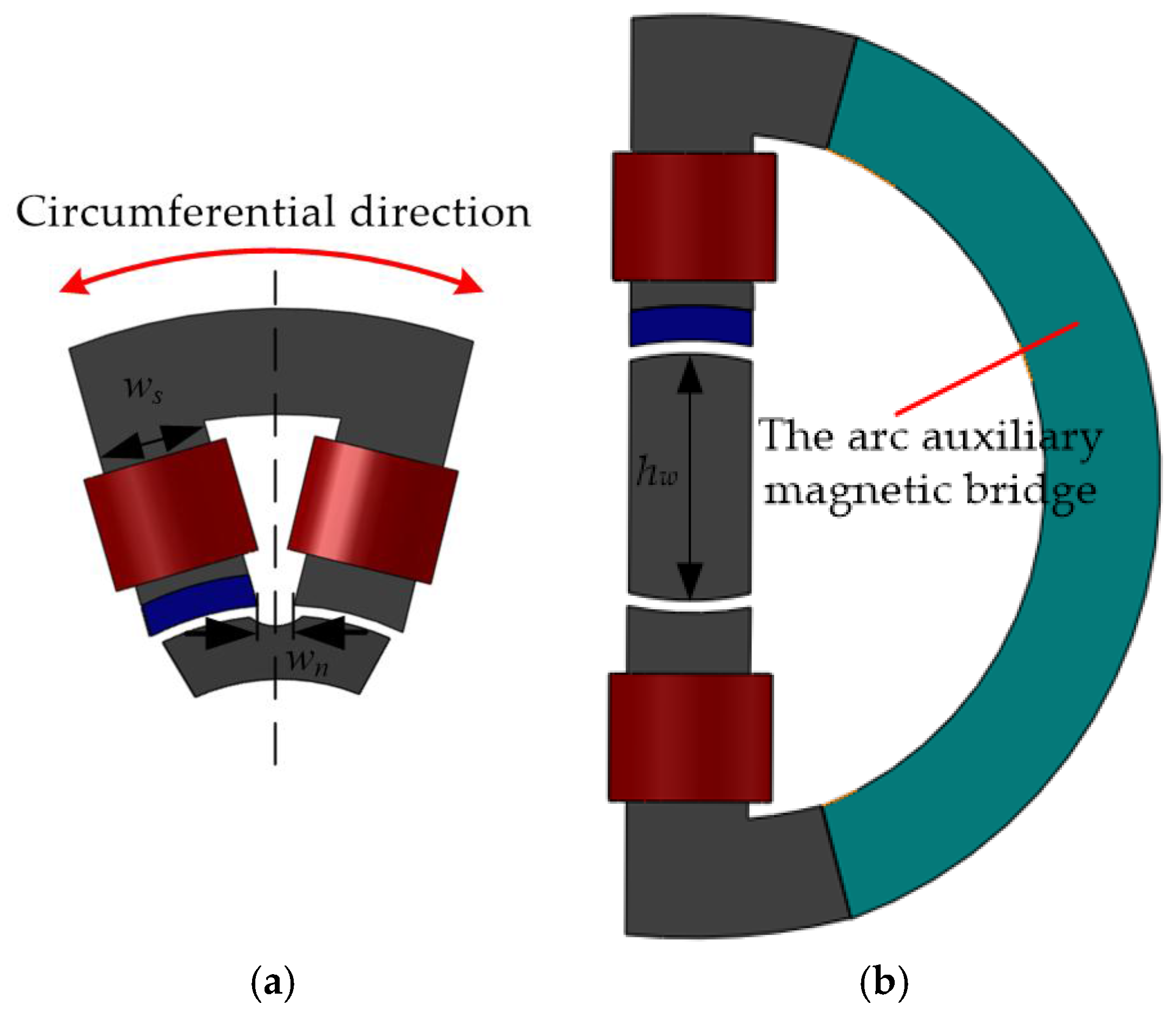
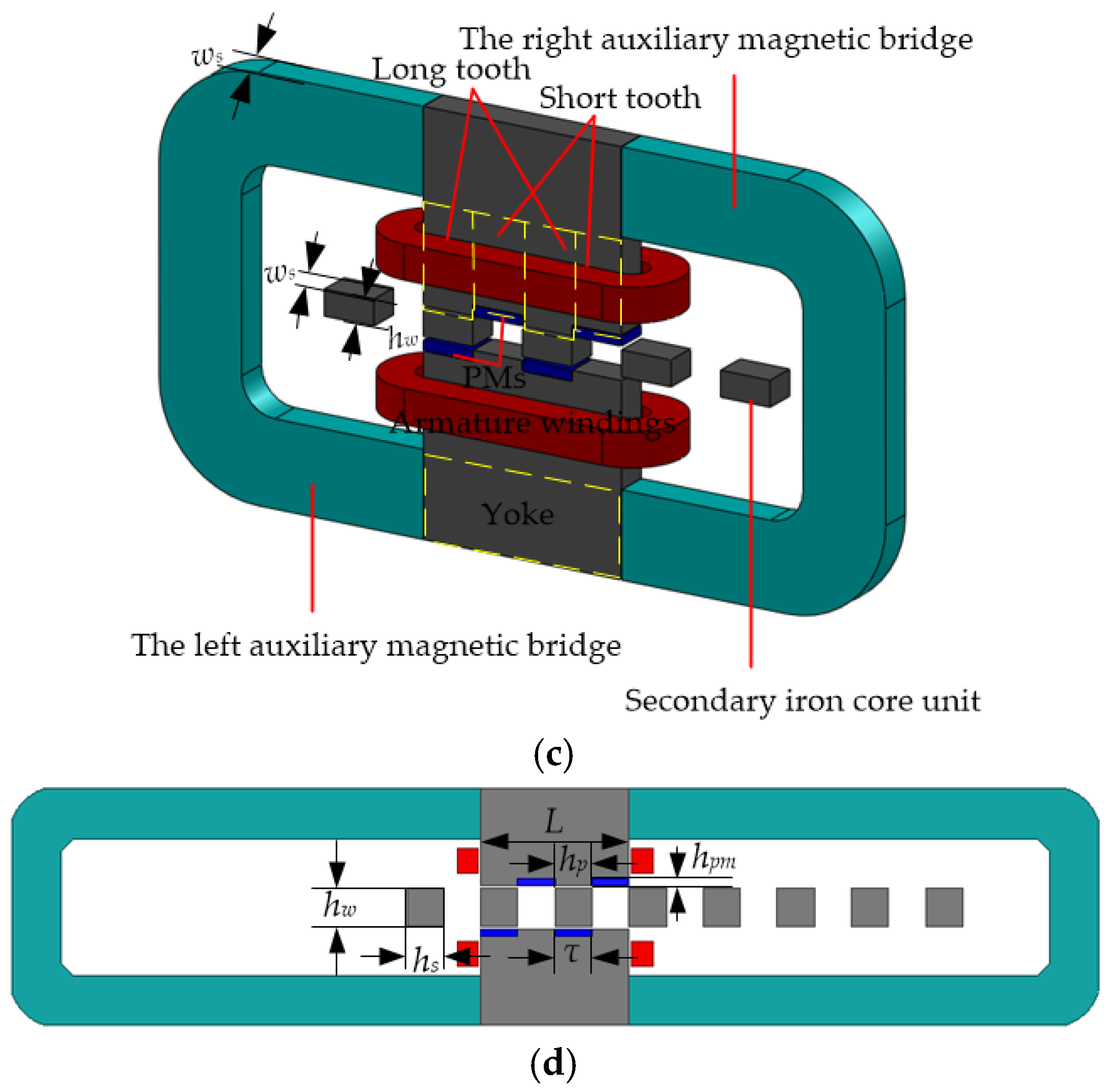
The equivalent methods are as follows, Figure 7a shows the axial diagram of unit machine. The yoke of the unit machine is stretched and extended along the circumferential direction, then, the circumferential stretching model is given, as shown in Figure 7b. The long and short tooth magnetic circuit is connected by an arc auxiliary magnetic bridge made of superconducting magnetic material. Furthermore, based on the circumferential stretching model, the equivalent 3D model of the unit machine is deduced, as shown in Figure 7c. The arc auxiliary magnetic bridge is divided into two parts, which are arranged at the left and right sides of the teeth, including the right auxiliary magnetic bridge and the left auxiliary magnetic bridge. Considering the circumferential leakage of the unit machine, in the equivalent process, the effective magnetic path length hw of the secondary iron core unit is equal to (wn + ws)/2, which improves the accuracy of the equivalent 3D model.
Based on the above equivalent method, the model of equivalent 2D FEM of the unit machine can be established, as shown in Figure 7d. The model depth De of the equivalent 2D FEM is the same as the width of the tooth ws. Table 1 shows the main design parameters of the unit machine and the model of equivalent 2D FEM.
4.1. Magnetic Field Analysis of the Unit Machine
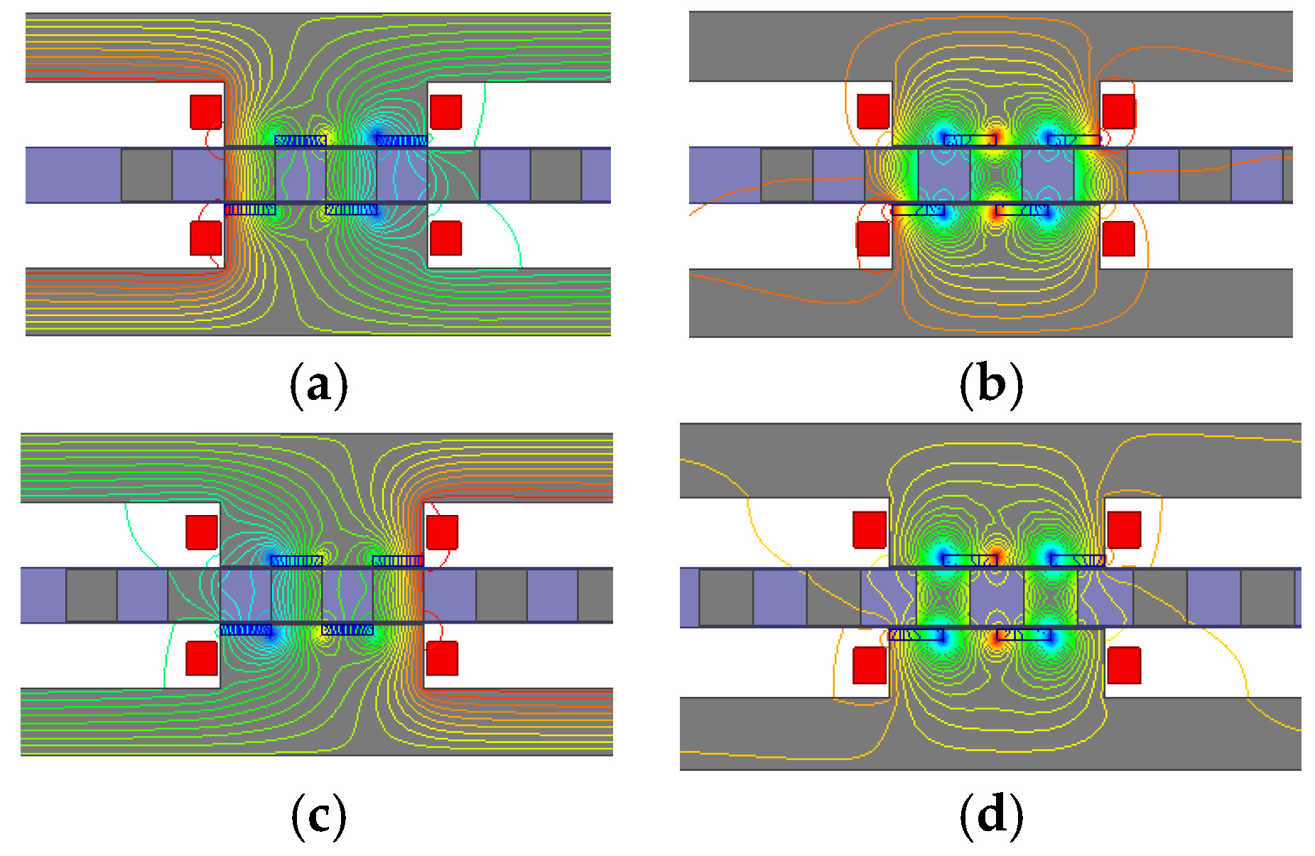
Figure 8 shows the magnetic field distribution diagram of the four typical electrical degrees positions of the unit machine under no-load condition. When the secondary iron core units are at the position of 0 electrical degrees, which is shown in Figure 8a, the main magnetic flux is the negative maximum. As shown in Figure 8c, at the position of 180 electrical degrees, the main magnetic flux is the positive maximum. As shown in Figure 8b,d, at the positions of 90 and 270 electrical degrees, the main magnetic flux is zero. As mentioned above, the magnetic flux is alternating from 0 to 270 electrical degrees positions. Therefore, the working principle of the unit machine is further verified. Meanwhile, as shown in Figure 8a,c, we can know that the leakage magnetic flux mainly consists of end leakage magnetic flux, circumferential, and axial leakage magnetic flux of PM. The axial leakage magnetic flux of PM is the largest proportion of all leakage magnetic flux, which is the main factor that influences the utilization ratio of the PM and the power factor of the machine.
4.2. Harmonic Analysis of the No-Load Back-EMF
The no-load back-EMF of the primary consequent-pole TTFFRLM can be obtained by changing the initial position of the secondary of the unit machine according to the principle of three-phase machine. Figure 9 shows the simulation waveform of the no-load back-EMF by the equivalent 2D FEM. As shown in Figure 9a, the phase difference of the phase no-load back-EMF is 120 electrical degrees and the amplitude of the phase back-EMF is equal. The amplitude of the line no-load back-EMF is 9.9 V when the movement velocity of the secondary is 1 m/s, as shown in Figure 9b.
Figure 10 shows the percentage of each harmonic components of back-EMF relative to the fundamental wave. As shown, the harmonic components of the phase back-EMF is mainly the third-order, the fifth-order, and the seventh-order harmonic. Because of the star connection type of the armature winding, the third-order harmonic of the line back-EMF is eliminated, but there are still the fifth-order and the seventh-order harmonic. The THD of the line back-EMF is 5.92%.
4.3. Detent Force and Electromagnetic Thrust Force
In order to illustrate the advantages of the primary consequent-pole TTFFRLM, the unit machine of the conventional TTFFRLM has been designed and modeled by the equivalent 2D FEM as according to the design parameters of Table 1. Figure 11 shows the model of equivalent 2D FEM of the unit machine of the conventional TTFFRLM.
Based on the models of the Figure 7d and Figure 11, the detent force, and the electromagnetic thrust force of the conventional TTFFRLM, and the primary consequent-pole TTFFRLM can be obtained according to the principle of three-phase machine.
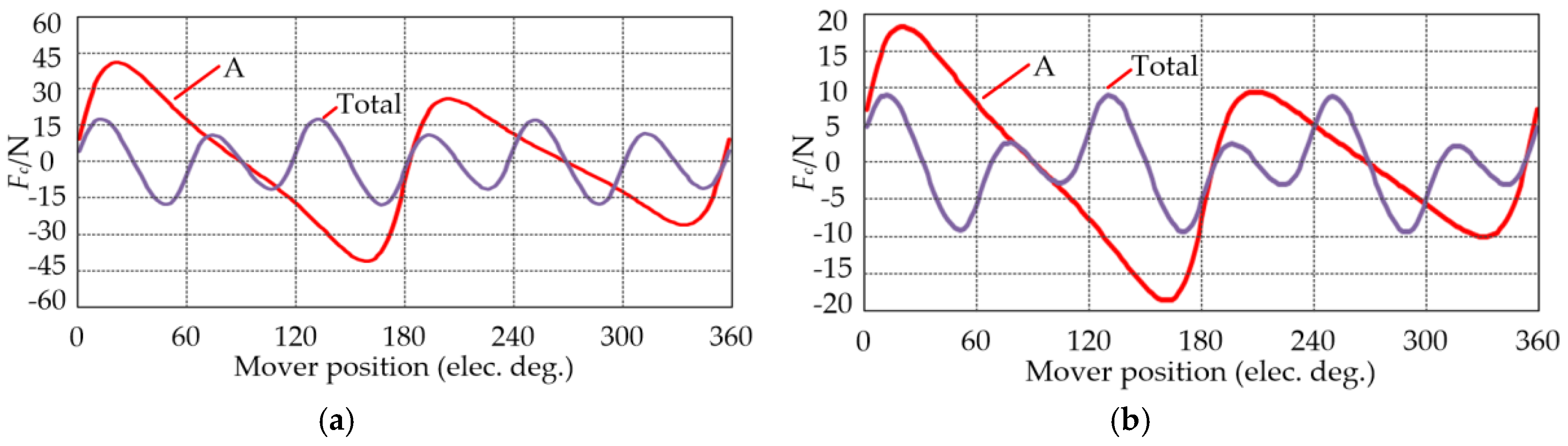
The detent force of the two machines are shown in Figure 12a,b. As shown, the periods of their A phase detent force are both τ, and the peak-peak values are 81.4 N and 35.7 N, respectively. However, the peak-peak value of the detent force in the first period is different from that in the second period, mainly due to the detent force at the end of the A phase [20]. The periods of the three-phase detent force are both τ/3, and the peak-peak values are 35 N and 17.4 N, respectively. Meanwhile, the peak fluctuation periods of the three-phase detent force are both 2τ/3.
Figure 13 shows the harmonic components of the three-phase detent force of the conventional TTFFRLM and the primary consequent-pole TTFFRLM. As shown, the harmonic components of the primary consequent-pole TTFFRLM are mainly the third-order and the sixth-order harmonic as same as the conventional TTFFRLM. The third-order harmonic and the sixth-order harmonic, respectively, correspond to the end detent force and the cogging detent force [20]. The end detent force of the two machines is almost the same, however, the cogging detent force of the primary consequent-pole TTFFRLM is much smaller than the conventional TTFFRLM, this is the main reason for the difference between the detent forces of the two machines.
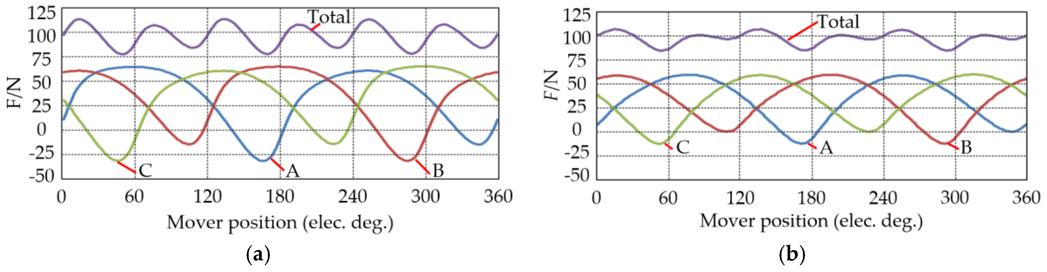
When the machine adopts id = 0 vector control algorithm, the phase of back-EMF is the same as the current. The electromagnetic thrust force of the conventional TTFFRLM and the primary consequent-pole TTFFRLM can be calculated by models of the equivalent 2D FEM of the two unit machines according to the principle of three-phase machine.
The electromagnetic thrust force of the two machines at rated current 7.5 A is shown in Figure 14. As shown, the phase electromagnetic thrust force of the two machines is negative in some areas because of the presence of the phase detent force. The three-phase electromagnetic thrust force of the two machines has six wave crests in an electric period because of the presence of the three-phase detent force. The average values of the three-phase electromagnetic thrust force of the conventional TTFFRLM and the primary consequent-pole TTFFRLM are 93.4 N and 95.4 N, respectively. Therefore, the primary consequent-pole TTFFRLM can save half of the amount of PMs than the conventional TTFFRLM. In addition, the peak-peak values of the three-phase electromagnetic thrust force of the conventional TTFFRLM and the primary consequent-pole TTFFRLM are 34.6 N and 21.7 N, respectively. The three-phase electromagnetic thrust force ripple of the two machines are 37% and 23%, respectively. It indicates that the primary consequent-pole TTFFRLM has smaller electromagnetic thrust force ripple.
5. Test Results and Analysis of the Prototype
In order to verify the correctness and effectiveness of topology, model, and analysis method of the proposed primary consequent-pole TTFFRLM, based on design parameters of Table 1, a three-phase 4-poles 12-slots primary consequent-pole TTFFRLM is designed and manufactured. The armature winding between the two unit machines in each phase is connected in series. The three-phase armature winding is star connected. The PMs are bonded to the inner surface of the short tooth by high strength and high temperature resistant structural adhesive.
Figure 15 shows the physical maps of the primary iron core unit and the secondary iron core unit. As shown in Figure 15a, the tooth and yoke of the primary iron core unit can be shaped by pressing die at once with silicon steel sheet, and the dovetail boss is used for mechanical fixing.
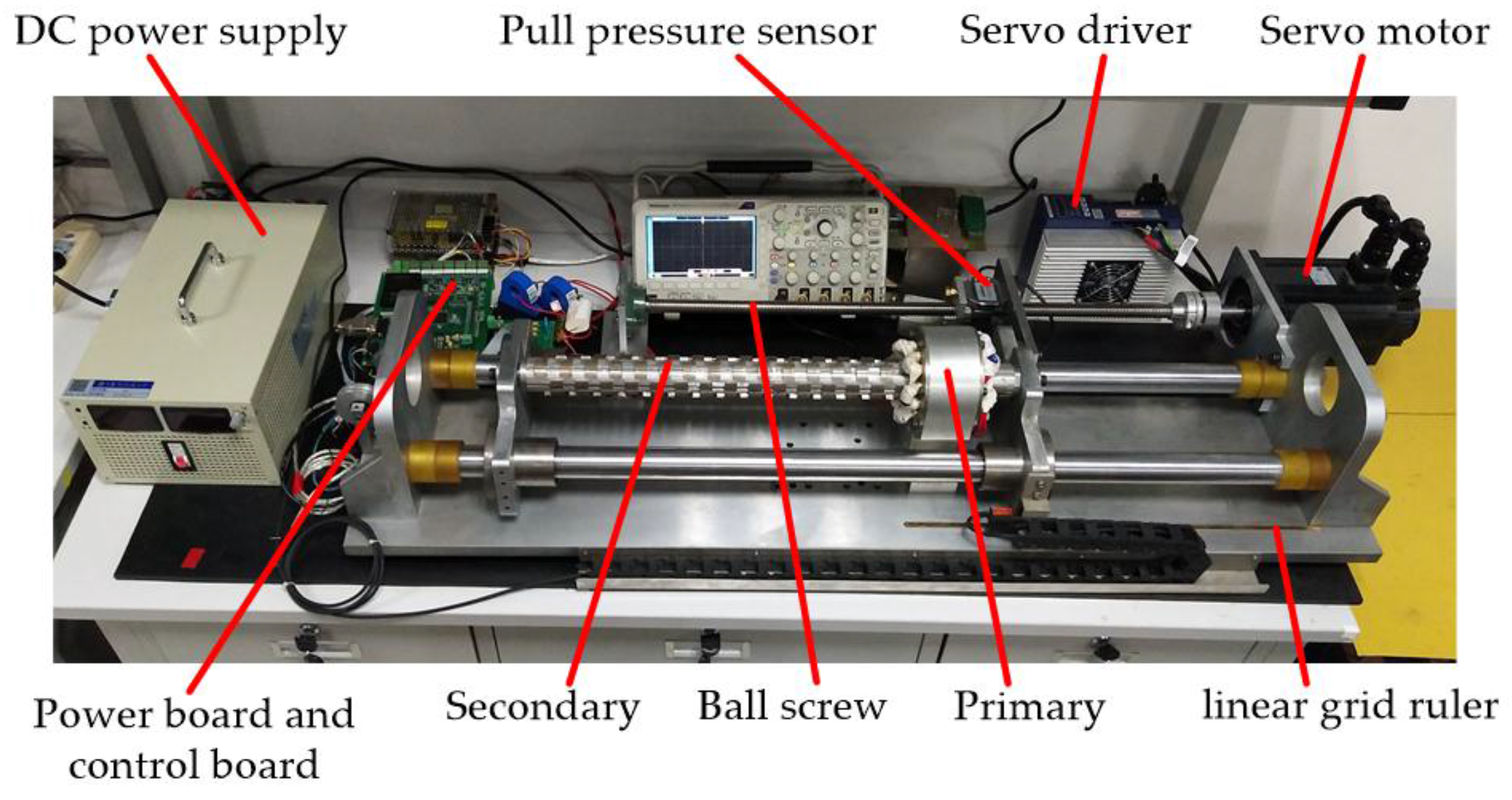
Figure 16 shows the sketch map of the experiment platform. As shown, the experiment platform mainly consists of DC power supply, pull pressure sensor, servo driver, servo motor, ball screw, linear grid ruler, power board, control board, the primary and the secondary. The primary is fixed on the base of the experiment platform. The secondary can be axially moved along the guide shaft by four linear bearings.
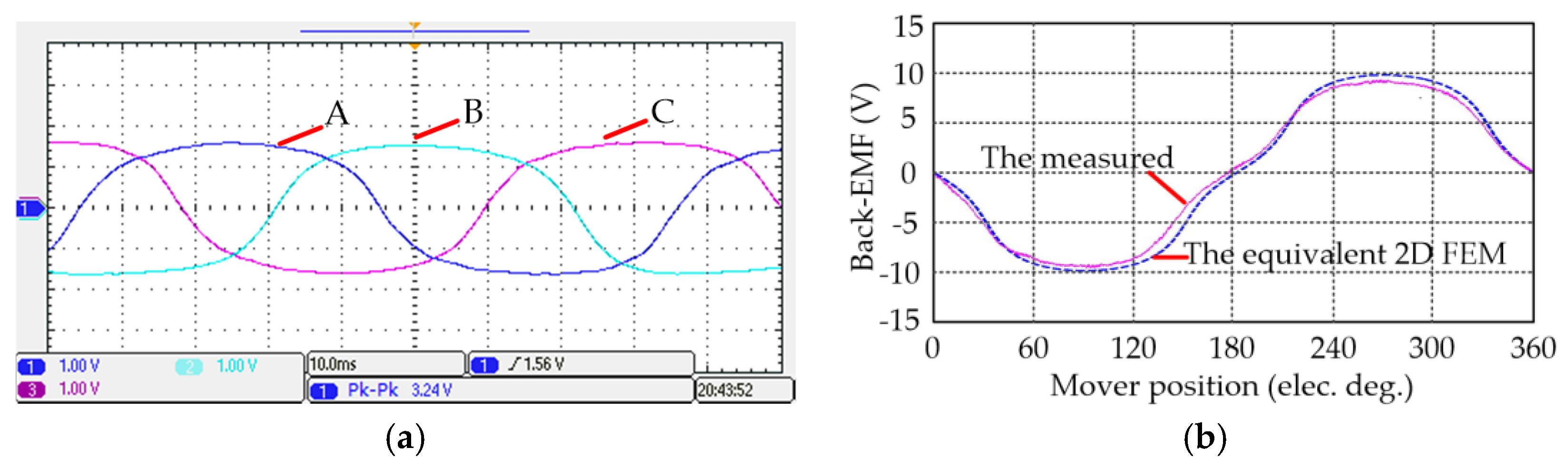
Figure 17 shows the measured waveform of the no-load back-EMF. As shown, the amplitude of the each phase no-load back-EMF is equal and the phase difference is 120 electrical degrees, the validity and correctness of the design method of the proposed primary consequent-pole TTFFRLM are verified. Figure 17b shows the measured value of the line no-load back-EMF at v = 1 m/s. As shown, the measured amplitude is about 9.2 V, the value is 7.1% less than the simulation value of the equivalent 2D FEM shown in Figure 9b.
Figure 18 shows the measured waveform of the total detent force of the primary consequent-pole TTFFRLM. As shown, the measured waveform is basically consistent with the trend of simulation waveform of the equivalent 2D FEM. The measured peak-peak value is 18.3 N, the value is 5% more than the simulation value 17.4 N of the equivalent 2D FEM shown in Figure 12b.
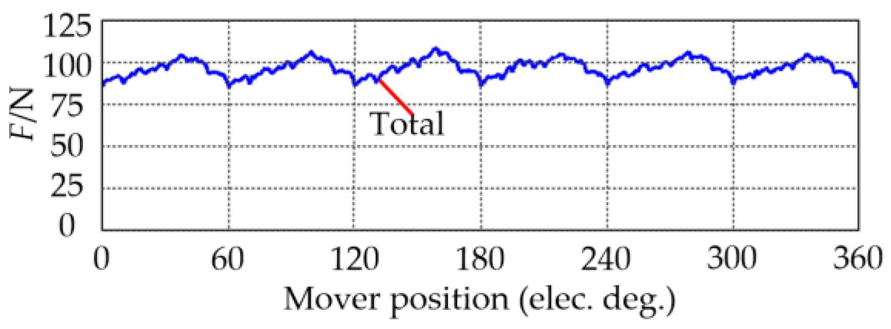
As shown in Figure 16, when the servo motor drives the ball screw at a certain speed, the secondary moves from right to left in a straight line. Meanwhile, a three-phase alternating current is fed into the three-phase armature winding by id = 0 vector control algorithm. Then the electromagnetic thrust force in opposition to the motion of the secondary to block secondary movement is produced, and the electromagnetic thrust force can be measured by the pull pressure sensor. Figure 19 shows the measured waveform of the total electromagnetic thrust force when the rated current is 7.5 A at v = 4.16 mm/s. As shown, the measured waveform of the total electromagnetic thrust force is basically consistent with the trend of simulation waveform. The measured average value of the total electromagnetic thrust force is 92.6 N, the value is 3% less than the simulation value 95.4 N shown in Figure 14b. The peak-peak value of the total electromagnetic thrust force is 22.4 N, then the total electromagnetic thrust force ripple is 24.1%, the value is 3.2% more than the simulation value 23% shown in Figure 14b.
6. Conclusions
In this paper, a novel primary consequent-pole TTFFRLM for long stroke drive systems is proposed. The structure and operating principle of the machine are researched. Based on the magnetic circuit method and the equivalent 2D FEM, the static characteristics are analyzed. The simulation and experimental results verify the correctness and effectiveness of the topology and design method of proposed machine. Through the study of this paper, the following conclusions are obtained:
- (1)
- The primary is easily manufactured, and the secondary is only composed of magnetically conductive iron cores, which can reduce the application cost of the long stroke drive systems.
- (2)
- The dual N poles type of the PMs distributed in the circumferential direction can reduce circumferential leakage magnetic flux and improve the utilization ratio of PM.
- (3)
- When compared with conventional TTFFRLM, the proposed machine can save half the amount of PMs. Meanwhile, the electromagnetic thrust force ripple is much smaller.
As a new machine, in future, there are many aspects deserved further investigation, such as detent force, electromagnetic thrust force ripple, and electromagnetic thrust force density, and so on.
Acknowledgments
This work was supported in part by the National Natural Science Foundation of China (51277095, 51507079, 51777096) and ESTUN AUTOMATION TECHNOLOGY Co., LTD.
Author Contributions
Dingfeng Dong and Wenxin Huang conceived and designed the experiments; Dingfeng Dong and Qi Wang performed the experiments; Feifei Bu and Wen Jiang analyzed the data; Xiaogang Lin contributed analysis tools; Dingfeng Dong wrote the paper.
Conflicts of Interest
The authors declare no conflict of interest.
References
- Kou, B.Q.; Wu, H.X.; Li, L.Y.; Zhang, L.L.; Zhao, Z.; Cao, H.C. The thrust characteristics investigation of double-side plate permanent magnet linear synchronous motor for EML. IEEE Trans. Magn. 2009, 45, 501–505. [Google Scholar]
- Hasanien, H.M.; Abd-Rabou, A.S.; Sakr, S.M. Design optimization of transverse flux linear motor for weight reduction and performance improvement using response surface methodology and genetic algorithms. IEEE Trans. Energy Convers. 2010, 25, 598–605. [Google Scholar] [CrossRef]
- Li, L.Y.; Pan, D.H.; Huang, X.Z. Analysis and optimization of ironless permanent-magnet linear motor for improving thrust. IEEE Trans. Plasma Sci. 2013, 41, 1188–1192. [Google Scholar] [CrossRef]
- Chen, M.Y.; Lu, J.S. High-precision motion control for a linear permanent magnet Iron core synchronous motor drive in position platform. IEEE Trans. Ind. Inform. 2014, 10, 99–108. [Google Scholar] [CrossRef]
- Chung, S.U.; Kim, J.M. Double-sided iron-core PMLSM mover teeth arrangement design for reduction of detent force and speed ripple. IEEE Trans. Ind. Electron. 2016, 63, 3000–3008. [Google Scholar] [CrossRef]
- Song, J.C.; Dong, F.; Zhao, J.W.; Lu, S.L.; Li, L.; Pan, Z.B. A new design optimization method for permanent magnet synchronous linear motors. Energies 2016, 9, 992. [Google Scholar] [CrossRef]
- Cao, R.W.; Cheng, M.; Mi, C.C.; Hua, W. Influence of leading design parameters on the force performance of a complementary and modular linear flux-switching permanent-magnet motor. IEEE Trans. Ind. Electron. 2014, 61, 2165–2175. [Google Scholar] [CrossRef]
- Chung, S.U.; Lee, H.J.; Hwang, S.M. A novel design of linear synchronous motor using FRM topology. IEEE Trans. Magn. 2008, 44, 1514–1517. [Google Scholar] [CrossRef]
- Zhu, Z.Q.; Chen, X.; Chen, J.T.; Howe, D.; Dai, J.S. Novel linear flux switching permanent magnet machines. In Proceedings of the 2008 11th International Conference on Electrical Machines and Systems (ICEMS), Wuhan, China, 17–20 October 2008; pp. 2948–2953. [Google Scholar]
- Lu, Q.F.; Li, Y.X.; Ye, Y.Y.; Fang, Y.T. A novel transverse-flux switched-flux PM linear motor. In Proceedings of the 2013 16th International Conference on Electrical Machines and Systems (ICEMS), Busan, Korea, 26–29 October 2013; pp. 1907–1912. [Google Scholar]
- Urban, C.; Gunther, R.; Nagel, T.; Richter, R.; Witt, R. Development of a bendable permanent-magnet tubular linear motor. IEEE Trans. Magn. 2012, 48, 2367–2373. [Google Scholar] [CrossRef]
- Bianchi, N.; Bolognani, S.; Corte, D.D.; Tonel, F. Tubular linear permanent magnet motors: An overall comparison. IEEE Trans. Ind. Appl. 2003, 39, 466–475. [Google Scholar] [CrossRef]
- Wang, J.B.; Wang, W.Y.; Atallah, K.; Howe, D. Design considerations for tubular flux-switching PM machines. IEEE Trans. Magn. 2008, 44, 4026–4032. [Google Scholar] [CrossRef]
- Yan, L.; Li, W.; J, Z.X.; Chen, C.Y.; Chen, I.M. Design and modeling of three-phase tubular linear flux-switching permanent magnet motor. In Proceedings of the 2014 IEEE Chinese Guidance, Navigation and Control Conference, Yantai, China, 8–10 August 2014; pp. 2675–2680. [Google Scholar]
- Du, Y.; Chau, K.T.; Cheng, M.; Fan, Y.; Wang, Y.B.; Hua, W.; Wang, Z. Design and analysis of linear stator permanent magnet vernier machines. IEEE Trans. Magn. 2011, 47, 4219–4222. [Google Scholar] [CrossRef] [Green Version]
- Du, Y.; Chau, K.T.; Cheng, M.; Fan, Y.; Zhao, W.; Li, F. A linear stator permanent magnet vernier HTS machine for wave energy conversion. IEEE Trans. Appl. Supercond. 2012, 22, 5202505. [Google Scholar] [CrossRef]
- Ji, J.H.; Zhao, J.X.; Zhao, W.X.; Fang, Z.Y.; Liu, G.H.; Du, Y. New high force density tubular permanent-magnet motor. IEEE Trans. Appl. Supercond. 2014, 24, 1–5. [Google Scholar] [CrossRef]
- Boldea, I.; Nasar, S.A.; Penswick, B.; Ross, B.; Olan, R. New linear reciprocating machine with stationary permanent magnets. In Proceedings of the 1996 Industry Applications Conference, 31th IAS Annual Meeting, San Diego, CA, USA, 6–10 October 1996; pp. 825–829. [Google Scholar]
- Boldea, I.; Wang, C.X.; Yang, B.; Nasar, S.A. Analysis and design of flux-reversal linear permanent magnet oscillating machine. In Proceedings of the 1998 Industry Applications Conference, 33th IAS Annual Meeting, St. Louis, MO, USA, 12–15 October 1998; pp. 136–143. [Google Scholar]
- Kou, B.Q.; Luo, J.; Yang, X.B.; Zhang, L. Modeling and analysis of a novel transverse-flux flux-reversal linear motor for long-stroke application. IEEE Trans. Ind. Electron. 2016, 63, 6238–6248. [Google Scholar] [CrossRef]
- Wang, Q.; Zou, J.M.; Zou, J.B.; Zhao, M. Analysis and computer-aided simulation of cogging force characteristic of a linear electromagnetic launcher with tubular transverse flux machine. IEEE Trans. Plasma Sci. 2011, 39, 157–161. [Google Scholar] [CrossRef]
Figure 1.
The structure diagram of the TTFFRLM: (a) The conventional TFFRLM; (b) The primary consequent-pole TFFRLM; (c) The primary; (d) The secondary; (e) The sketch of evolution of primary iron core unit; and, (f) The primary iron core of the unit machine.
Figure 1.
The structure diagram of the TTFFRLM: (a) The conventional TFFRLM; (b) The primary consequent-pole TFFRLM; (c) The primary; (d) The secondary; (e) The sketch of evolution of primary iron core unit; and, (f) The primary iron core of the unit machine.
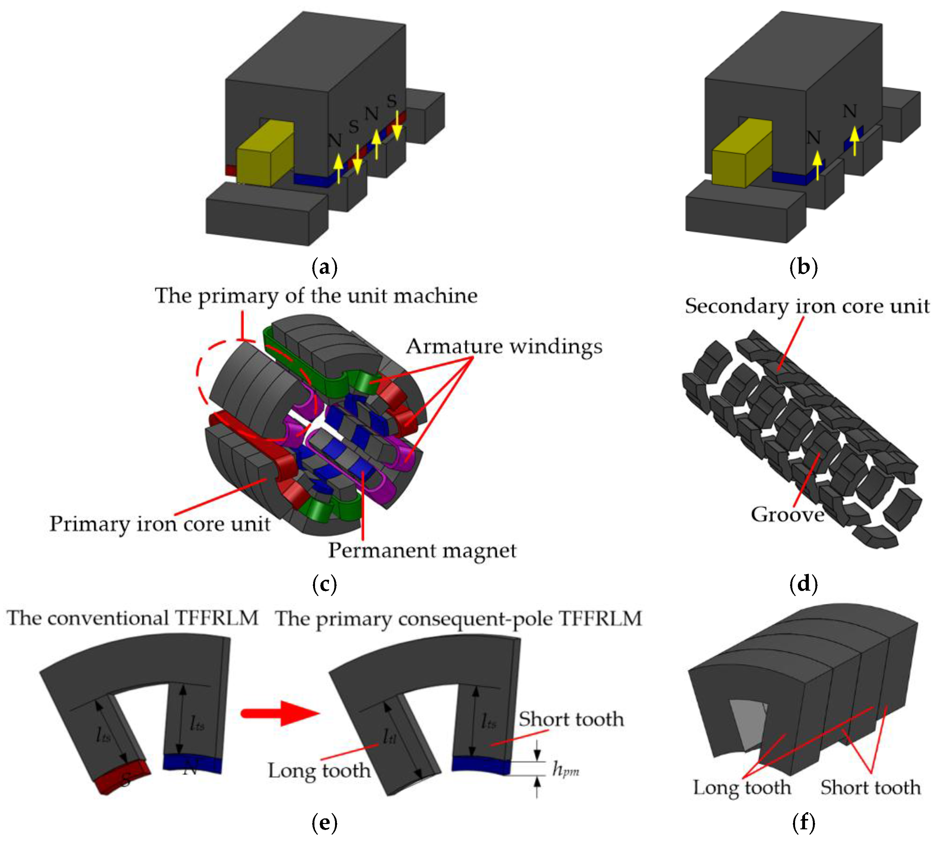
Figure 2.
The circumferential outspread diagram of the secondary.

Figure 3.
Outspread diagram of the machine topology.
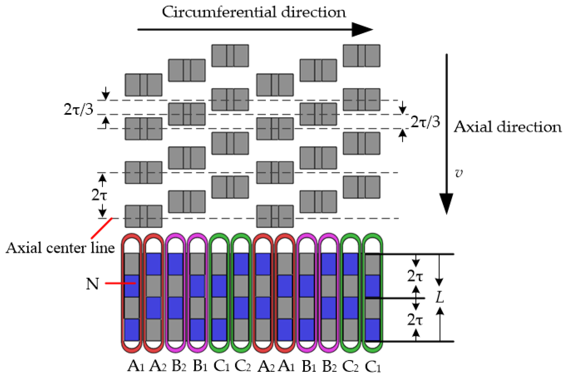
Figure 4.
Working principle of the A phase: (a) The secondary position a; (b) The secondary position b; (c) The secondary position c; (d) The secondary position d; (e) The flux linkage; and, (f) The back-EMF.
Figure 4.
Working principle of the A phase: (a) The secondary position a; (b) The secondary position b; (c) The secondary position c; (d) The secondary position d; (e) The flux linkage; and, (f) The back-EMF.
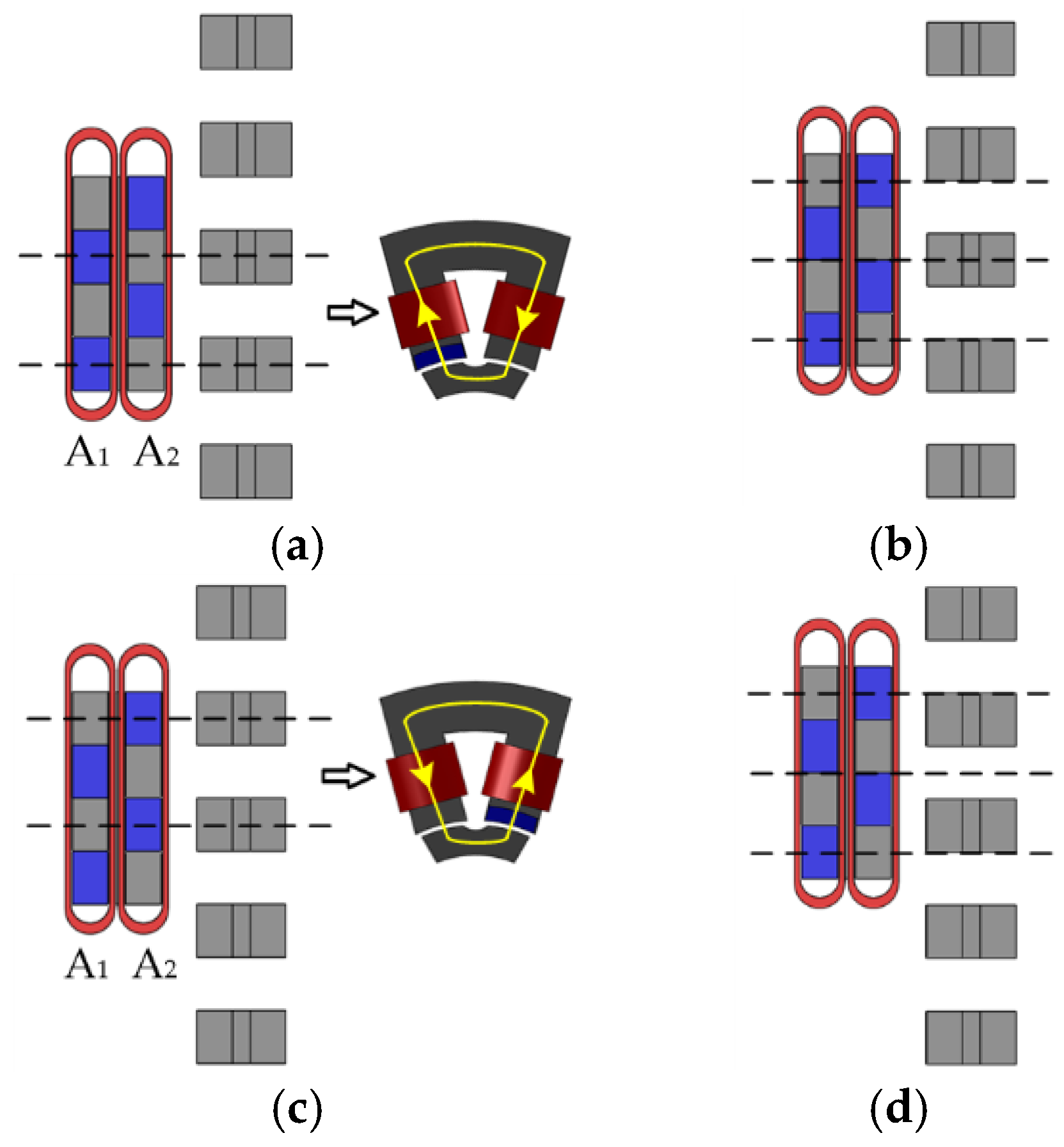

Figure 5.
Structure diagram of the unit machine.

Figure 6.
Equivalent magnetic circuit model of the unit machine.

Figure 7.
The equivalent model of the unit machine: (a) The axial diagram of unit machine; (b) The circumferential stretching model; (c) Equivalent 3D model; (d) The model of equivalent 2D finite element method (FEM).
Figure 7.
The equivalent model of the unit machine: (a) The axial diagram of unit machine; (b) The circumferential stretching model; (c) Equivalent 3D model; (d) The model of equivalent 2D finite element method (FEM).


Figure 8.
The distribution of magnetic flux lines: (a) The 0 electrical degrees position; (b) The 90 electrical degrees position; (c) The 180 electrical degrees position; and, (d) The 270 electrical degrees position.
Figure 8.
The distribution of magnetic flux lines: (a) The 0 electrical degrees position; (b) The 90 electrical degrees position; (c) The 180 electrical degrees position; and, (d) The 270 electrical degrees position.

Figure 9.
No-load back-EMF: (a) The three-phase; (b) The line.
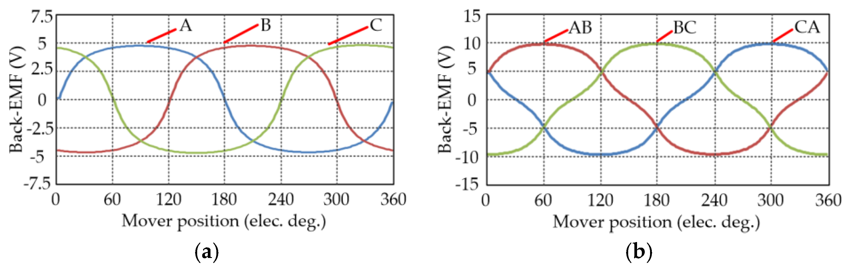
Figure 10.
The percentage of each harmonic components of back-EMF relative to the fundamental wave.
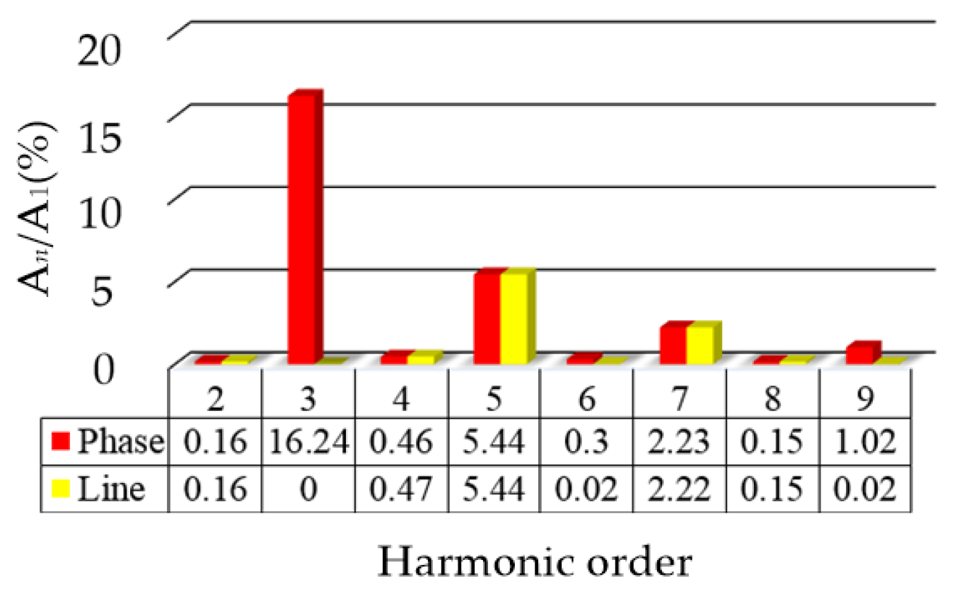
Figure 11.
The model of equivalent 2D FEM of the unit machine of the conventional TTFFRLM.

Figure 12.
The waveform of the detent force: (a) The conventional TTFFRLM; (b) The primary consequent-pole TTFFRLM.
Figure 12.
The waveform of the detent force: (a) The conventional TTFFRLM; (b) The primary consequent-pole TTFFRLM.

Figure 13.
Harmonic components of the three-phase detent force of the two machines.
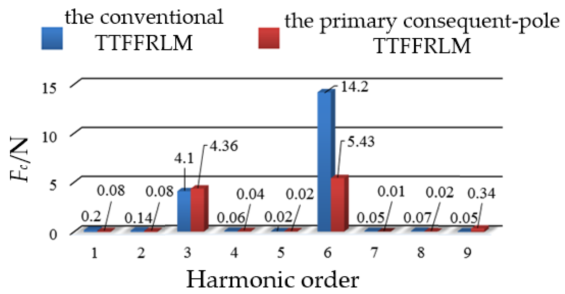
Figure 14.
The waveform of the electromagnetic thrust force at 7.5 A: (a) The conventional TTFFRLM; and, (b) The primary consequent-pole TTFFRLM.
Figure 14.
The waveform of the electromagnetic thrust force at 7.5 A: (a) The conventional TTFFRLM; and, (b) The primary consequent-pole TTFFRLM.

Figure 15.
Iron core units: (a) The primary; (b) The secondary.
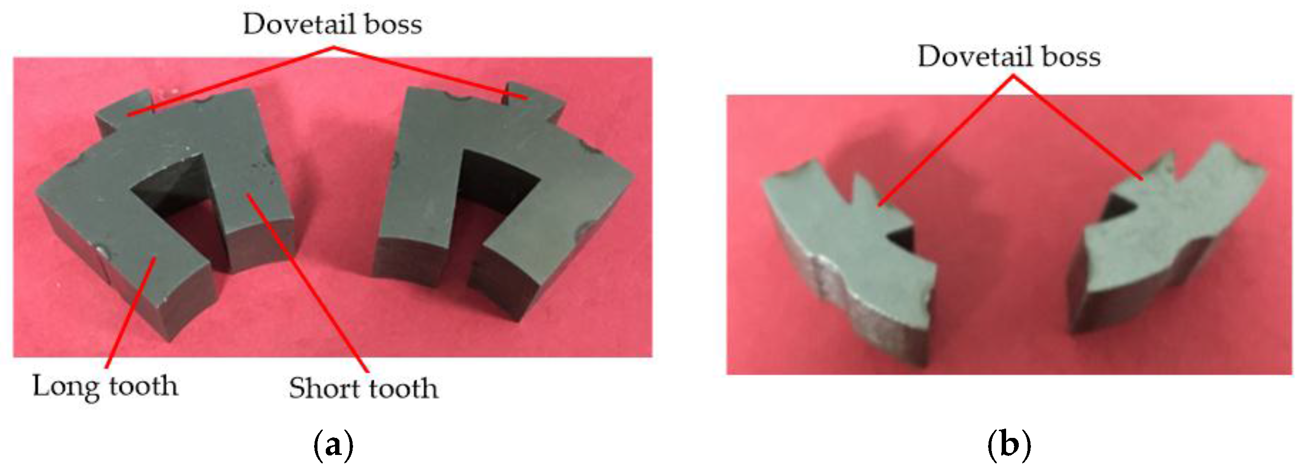
Figure 16.
Experiment platform.

Figure 17.
The measured no-load back-EMF: (a) The phase; (b) The line.

Figure 18.
The measured waveform of the total detent force.
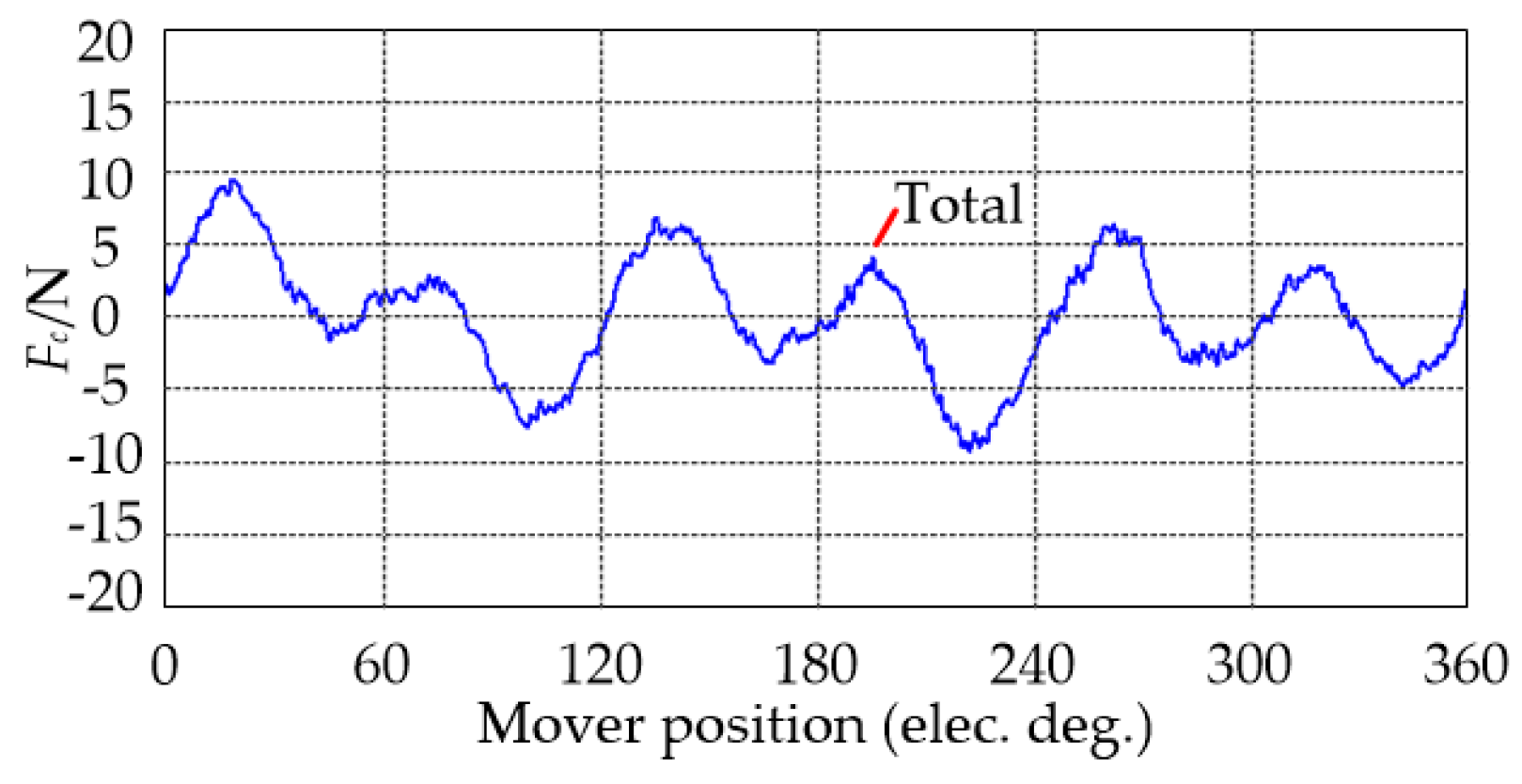
Figure 19.
The measured waveform of the total electromagnetic thrust force.


Table 1.
The design parameters of unit machine and model of equivalent 2D FEM.
| Parameter(Unit) | Symbol | Value |
|---|---|---|
| Outer diameter (mm) | Do | 100 |
| Internal diameter (mm) | Di | 54 |
| Primary iron core length (mm) | L | 60 |
| Minimum mechanical airgap (mm) | g | 1 |
| Pole-pitch (mm) | τ | 15 |
| PM thickness (mm) | hpm | 3 |
| PM width (mm) | wpm | 10 |
| Primary iron core unit thickness (mm) | hp | 15 |
| The width of the tooth (mm) | ws | 10 |
| The length of the short tooth (mm) | lts | 15.2 |
| The length of the long tooth (mm) | ltl | 18.2 |
| The width of the notch (mm) | wn | 4 |
| The bottom width of the slot (mm) | wb | 13 |
| Secondary iron core unit thickness (mm) | hs | 15 |
| The effective magnetic path length (mm) | hw | 7.5 |
| The model depth of the equivalent 2D FEM (mm) | De | 10 |
| The number of turns of the unit machine armature winding in series | N | 150 |
| PM residual flux density (T) | Br | 1.3 |
| Rated current (A) | - | 7.5 |
© 2017 by the authors. Licensee MDPI, Basel, Switzerland. This article is an open access article distributed under the terms and conditions of the Creative Commons Attribution (CC BY) license (http://creativecommons.org/licenses/by/4.0/).
Share and Cite
MDPI and ACS Style
Dong, D.; Huang, W.; Bu, F.; Wang, Q.; Jiang, W.; Lin, X. Modeling and Static Analysis of Primary Consequent-Pole Tubular Transverse-Flux Flux-Reversal Linear Machine. Energies 2017, 10, 1479. https://doi.org/10.3390/en10101479
AMA Style
Dong D, Huang W, Bu F, Wang Q, Jiang W, Lin X. Modeling and Static Analysis of Primary Consequent-Pole Tubular Transverse-Flux Flux-Reversal Linear Machine. Energies. 2017; 10(10):1479. https://doi.org/10.3390/en10101479
Chicago/Turabian StyleDong, Dingfeng, Wenxin Huang, Feifei Bu, Qi Wang, Wen Jiang, and Xiaogang Lin. 2017. "Modeling and Static Analysis of Primary Consequent-Pole Tubular Transverse-Flux Flux-Reversal Linear Machine" Energies 10, no. 10: 1479. https://doi.org/10.3390/en10101479
Note that from the first issue of 2016, this journal uses article numbers instead of page numbers. See further details here.