Flexibility-Based Reserve Scheduling of Pumped Hydroelectric Energy Storage in Korea


Department of Energy System Engineering, Chung-Ang University, 84 Heukseok-ro, Dongjak-gu, Seoul 06974, Korea
*
Author to whom correspondence should be addressed.
Energies 2017, 10(10), 1478; https://doi.org/10.3390/en10101478
Submission received: 28 August 2017
/
Revised: 15 September 2017
/
Accepted: 22 September 2017
/
Published: 24 September 2017
(This article belongs to the Special Issue Risk-Based Methods Applied to Power and Energy Systems)
Abstract
:The high penetration of renewable energy resources has made it harder to secure a flexible power system. Accordingly, this has become an issue in operating power systems. As a possible solution, pumped hydroelectric energy storage (PHES) has received much attention because of its fast start-up and ramp characteristics. This study proposes a flexibility-based reserve scheduling method for PHES. In this method, the reserve scheduling of PHES was conducted to improve flexibility; the associated risk index was termed the ramping capability shortage expectation (RSE). The peak-load days in 2016 and 2029 were selected to examine the applicability and performance of the proposed method. Results indicate that the proposed method can improve the flexibility by 4.45% for 2016 and 0.9% for 2029, respectively.
1. Introduction
In Korea, due to the post-2020 international climate regime and environmental issues related to air pollution or fine dust, the expansion of renewable energy has become a matter of some urgency [1,2]. However, integrating more renewable energy resources may deteriorate the flexibility of the power system. It has been reported that the intermittency and the variability of renewable energy resources can adversely affect flexibility [3]. To address this problem, the role of pumped hydroelectric storage (PHES) has received attention as a flexible resource; it has a fast start-up and ramping characteristics [4,5,6,7]. In Korea, the PHES start-up is 4 min, while those for a hot-start combined cycle gas turbine and hot-start coal steam turbine are 57 and 197 min, respectively. The PHES ramp rate is ten to twenty times higher than that of the combined cycle units [8]. Many countries have pursued this technology to cope with the flexibility issue [9]. For example, in the USA, the federal energy regulatory commission (FERC) has recently granted over 30 pre-permits totaling over 22,000 MW for PHES [10].
The PHES energy production cannot be greater than its reservoir energy, which may crucially affect power system reliability [11]. For example, on 15 September, 2011, PHESs were stopped because of the depletion of water in the upper reservoir, which resulted in cascading load shedding (i.e., a rolling blackout) in Korea [12,13]. This was due to the faster increase in temperature-sensitive loads than the response of reserve resources. The hourly increase was >4000 MW, and larger than the stand-by reserve of 2500 MW. The frequency dropped under 59.5 Hz, notwithstanding the continuous operation of reserve resources. Cheongsong PHES was exhausted; the first load shedding then occurred. The exhaustion of Samnyangjin PHES and the failure of the Daesan combined-cycle unit #1 resulted in a sharp decline of frequency, which caused the third and fourth load shedding. Muju and Yangyang PHESs were exhausted, and Sancheong PHES was also expected to be depleted in 30 min; finally, the fifth load shedding was enforced. The reserve capacity was regarded as always available, irrespective of the reservoir energy.
Since the 2011 outage event in Korea, a reserve scheduling method for PHES that considers the decrease in reservoir energy according to reserve capacity has been proposed [8]; the so-called uniform allocation method is applied to distribute the reserve capacity. This method has been used in some countries adopting centralized-operation [14,15]. The method may enhance the system reliability; however, it is limited in securing system flexibility because it does not account for the ramping capability requirement, which is essential for flexibility. Non-flexible generation and renewable energy resources are expected to reach 70% of the total installed capacity in Korea [16]. In this situation, a reserve scheduling method that can account for reservoir energy and also improve flexibility may be helpful.
Research has been conducted on PHES self-scheduling to maximize power generation company profits in energy and reserve markets [17,18,19,20,21]. These methods can reflect the decrease and increase in reservoir energy in accordance with pumping and generation. However, most of these studies did not fully consider system aspects, such as the ramping capability or related risk in their formulation. Accordingly, they are limited in reflecting the power system flexibility, although the reserve capacity is interlocked with the reservoir energy in their scheduling.
This study proposes a flexibility-based reserve scheduling method for PHES. This method is capable of securing the ramping capability requirement, and thereby improving the flexibility. The flexibility is evaluated using a risk index, termed the ramping capability shortage expectation (RSE), which captures the risk of a ramping capability shortage [22]. The peak-load days for 2016 and 2029 in Korea were selected for the case study. The simulation was used to compare the flexibility of the previous and proposed methods. The results for both years were compared.
The remainder of this paper is organized as follows. In Section 2, the RSE flexibility index is explained. Section 3 describes a reserve scheduling method for PHES. In Section 4, the case study for peak-load days in Korea is used to confirm the performance of the proposed method. The conclusions and future research perspectives are provided in Section 5.
2. Flexibility Index: Ramping Capability Shortage Expectation
Power system flexibility can be defined as the ability to cover the changes in net load. The ramping capability (RC), which is defined as the ability of a generator to change its power output in the targeted period, is an important component of providing flexibility [23]; larger RC values of the power system results in a greater flexibility. In this paper, a flexibility index, RSE, is used to capture the flexibility of the power system. The RSE calculation process is described as follows [22].
The system ramping capability (SRC) is calculated as the sum of RCs of all generators, and it is given by:
where Ai,t−Δt reflects the uncertainty in the generator; its value is computed using a Markov-chain-based generator model. This model calculates the probability that a generator will be unavailable, using transition rates between generator’s states and the probability matrix [24]. The evaluation target of SRCi is a generation schedule; each value of Oi,t−Δt, Pmax,i, and Pi,t−Δt is determined using a generation schedule. rri is a characteristic of each generating unit. Δt may differ with the time interval of the generation schedule in each system.
The RC requirement (RCR) in the net load side can be represented as follows:
where the net load forecasting error (NLFE) is:
FNLt is a deterministic value for each time t, while NLFEt, LFEt, and VGFEt, are stochastic values. The NLFEt, LFEt, and VGFEt are assumed to follow a Gaussian distribution. The inclusion of Ai,t−Δt in Equation (2) implies that RCRt is affected by generator failures; that is, unexpected failures of loading generators requires more ramping capability.
If RCRt is not satisfied by SRCt, a power imbalance occurs. This is called the ramping capability shortage, which accompanies load shedding. The RSPt is defined as the probability that the ramping capability shortage will occur at time t, and it is given by:
The RSE is calculated as follows:
where FNLt, Oi,t−Δt, and Pi,t−Δt are determined using a generation schedule. NLFEt and Ai,t−Δt are random variables; their values depend on uncertainty scenarios. Ci,t−Δt and Ei,t are sets representing uncertainty scenarios for generator failure and NLFEt, respectively. The forecast error information for the variable generation (VG) and load are factored in the uncertainty scenarios for NLFEt, i.e., Ei,t in Equation (4). Likewise, the generator failure states and their probability information are reflected in the uncertainty scenarios for generator failure, i.e., Ci,t−Δt in Equation (4).
The RSE has the following two characteristics: (1) the risk regarding increasing net load is only considered, and (2) the RSE calculation is applied to the worst case in time. The latter is useful for reducing the computational time in large power systems. Please refer to [22] for further information on the RSE.
3. Reserve Scheduling for Pumped Hydroelectric Storage
PHES pumps the water in a lower reservoir to an upper reservoir to store energy; the pumping action is considered as one of the power system loads. PHES cannot pump the water exceeding its reservoir energy. Likewise, it cannot also generate power exceeding its reservoir energy. The efficient use of the limited reservoir energy is of high importance. Two approaches are used for efficiently operating a PHES in a power system: energy and reserve scheduling [14,15]. For reference, some research has addressed these two types of scheduling together using co-optimizing techniques [20,25].
3.1. PHES Energy Scheduling
In a power system, PHES energy scheduling determines when and how much to pump and generate energy for a considered period. The operational costs of a power system can be reduced by cost-based PHES energy scheduling, which stores the energy produced from low-cost generators and produces energy instead of high-cost generators. For this energy scheduling to be effective, the following inequality should be satisfied:
Pumping cost ($/MWh) < energy price ($/MWh) × total efficiency of PHES
PHES may be operated even if the inequality above is not satisfied, for instance, when the system is expected to be unreliable. The PHES energy is then scheduled from highest to lowest demand. This is termed the reliability-based energy scheduling of PHES.
3.2. PHES Reserve Scheduling
PHES reserve scheduling determines the hourly reserve capacity for the supply period. Different from scheduled energy, the reserve capacity scheduling may or may not be used depending on conditions of the power system, although it is necessary to maintain reliability. Meanwhile, the PHES hourly reserve capacity directly relates to the water level in its upper reservoir. If the water level is not explicitly considered, then the reserve capacity of PHES may be false and may a cause serious outage in an emergency condition. The accident on 15 September, 2011 in Korea was an example of this type of mistake; the depletion of water led to load shedding. Therefore, PHES reserve scheduling should conducted based on reservoir energy.
3.2.1. Uniform Allocation Method
As a reserve scheduling method, allocating the same amount of reserve energy every hour is called the uniform allocation method. The supply period in this method is calculated based on the heavy-load duration, which is a period when the reserve capacity may be scarce, i.e., the system may be unreliable. The calculation procedure is as follows:
- A 24 h load profile for every month is calculated by averaging load values for every hour for every month, except for weekends and holidays.
- For every month, the heavy-load duration corresponds to the period when the hourly load is greater than a threshold value, here, this is determined as an average load value.
- The average value of the heavy-load duration for each season is applied to the PHES supply period.
For winter and summer periods in the latest year without demand-side management in Korea, the heavy-load duration, the period length when hourly load level is larger than its average value, for January, February, August, and December was 13 h; for July, September, and November it was 14 h; and, for March it was 15 h. The average value for the summer period, July, August, and September, it was 13.7 h, and that for the winter period, January, February, March, November, and December, it was 13.6 h. When rounding those values, the PHES supply period for both periods was 14 h.
The hourly reserve capacity is determined for the supply period. Under the given water level, the reserve energy of PHES i can be calculated as follows:
RCPi,t is then calculated by equally allocating REPi to each hour; it can be represented as follows:
Table 1 provides basic PHES information in Korea. The maximum available energy for every PHES is represented as the difference between its energy at full and minimum water levels. For reference, the PHES water level should be kept over the minimum water level for a black start. According to the uniform allocation method, if the REPi is 10% of the maximum available PHESi energy and the supply period is 12 h, i.e., Ts is 12 h, for a 24 h day, then the hourly reserve capacity of each PHES, i.e., RCPi,t, is calculated as in Table 2.
However, the result only reflects the reserve requirement of the system. This can improve the system reliability; however, this cannot reflect flexibility, which is a critical issue given the high penetration of renewable energy resources.
3.2.2. The Proposed Method
The supply period in the proposed method is computed based on the duration of high-ramping, which is a period when the ramping capability may be insufficient, i.e., the system may be inflexible. The supply period in the proposed method is described as follows:
- A 24 h load profile for every month is calculated by averaging load values for every hour of every month, except for weekends and holidays; this is identical to the uniform allocation method.
- For every month, the high-ramping duration corresponds to the period when the RSPt is greater than a threshold value; here, this is determined as an average RSPt value.
- The average high-ramping duration value for each season is applied to the PHES supply period.
Under the assumption that the water level is full, RCPi,t is then calculated by allocating REP to each hour in proportion to RSPt, which can be represented as follows:
Using Equation (9), the total reserve energy for all PHESs can then be allocated to improve flexibility.
A set of example RSPt values for a 24 h period is given in Table 3. The average value for the supply period is 0.35; accordingly, the high-ramping duration occurs between hours 7 and 18, i.e., Ts is 12 h. If 10% of the maximum available energy for all PHESs in Korea is allocated based on the proposed method, then the RCPi,t for the supply period is calculated as in Table 4.
4. Case Study
4.1. Basic Information
The main purpose of this simulation is to confirm the effect of the proposed PHES reserve scheduling on the flexibility of the Korean power system. A peak-load day in 2016 was used for the simulation; it was the last peak-load day in the year [26]. The installed PHES capacity is 4700 MW, which is 5% of the total installed capacity. For simplicity, it is assumed that the water level of PHES is full. The generator information and their failure and repair rates can be referenced in [16,24], respectively. The generators in Korea are divided into dispatchable and non-dispatchable units; the former are categorized into the following types: Cogeneration, combined-cycle (using both gas and steam turbines), hydraulic/pumped hydraulic, nuclear-power, and steam-turbine units. The latter are classified into VG and Non-VG, which include new-energy units, biofuel, fuel cell, and waste power, with <20 MW capacity and units owned by the community energy service provider [27]. The NLFE is represented with a Gaussian distribution, with a standard deviation of 5%. The generation schedule was solved using M-CoreS, which is a commercial simulation program for the Korean electricity market [28]. The latest regulations for the Korean electricity market were applied for this simulation [15]. The reliability-based energy scheduling of PHES is used for the simulation. The RSE for the generation schedule was calculated using the MATLAB program (R2012b version) [29]. The simulation programs were run on a PC with a 3.70 GHz Intel Core i3-6100 CPU, 16 GB of RAM, and 64-bit Windows 7.
4.2. Result for the Peak-Load Day in 2016
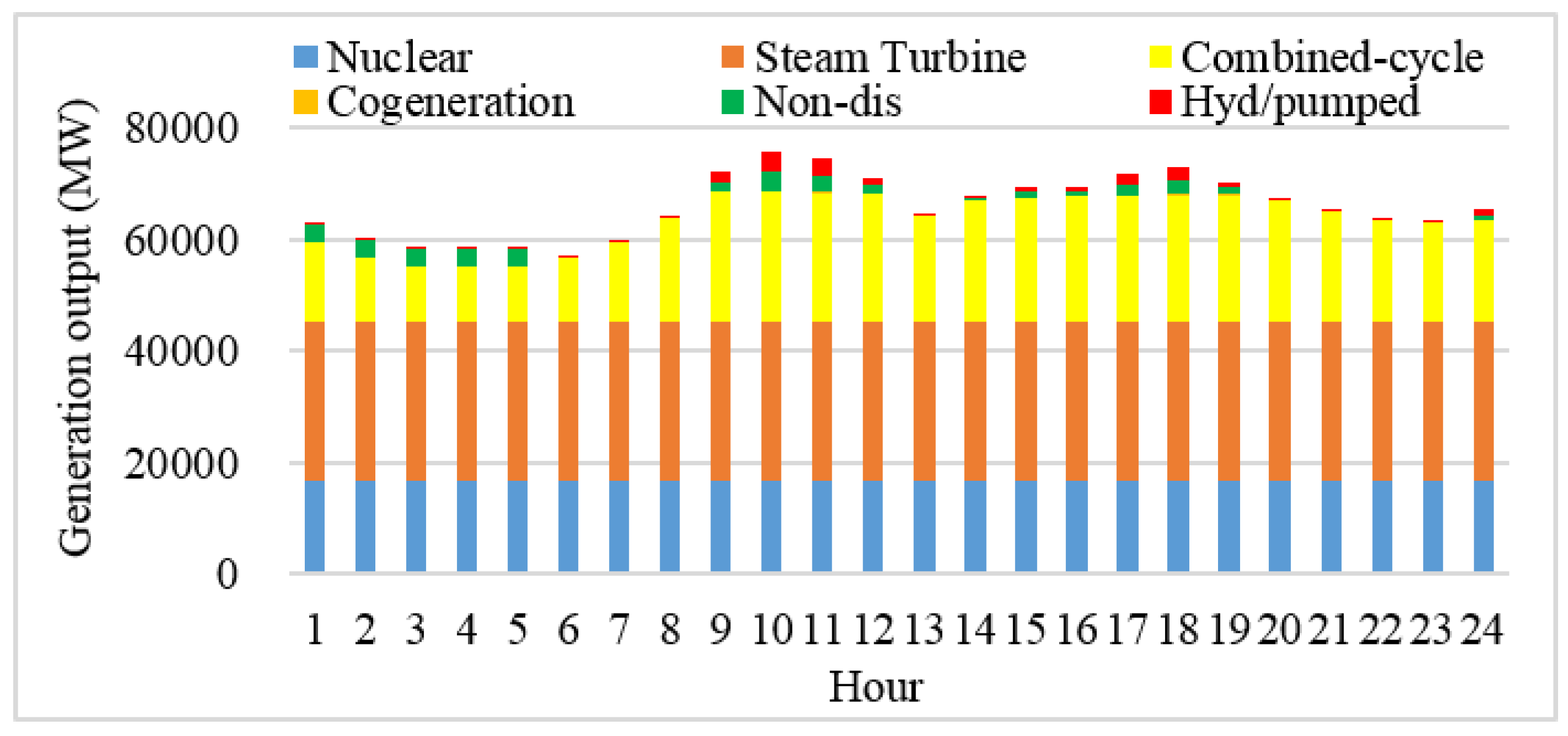
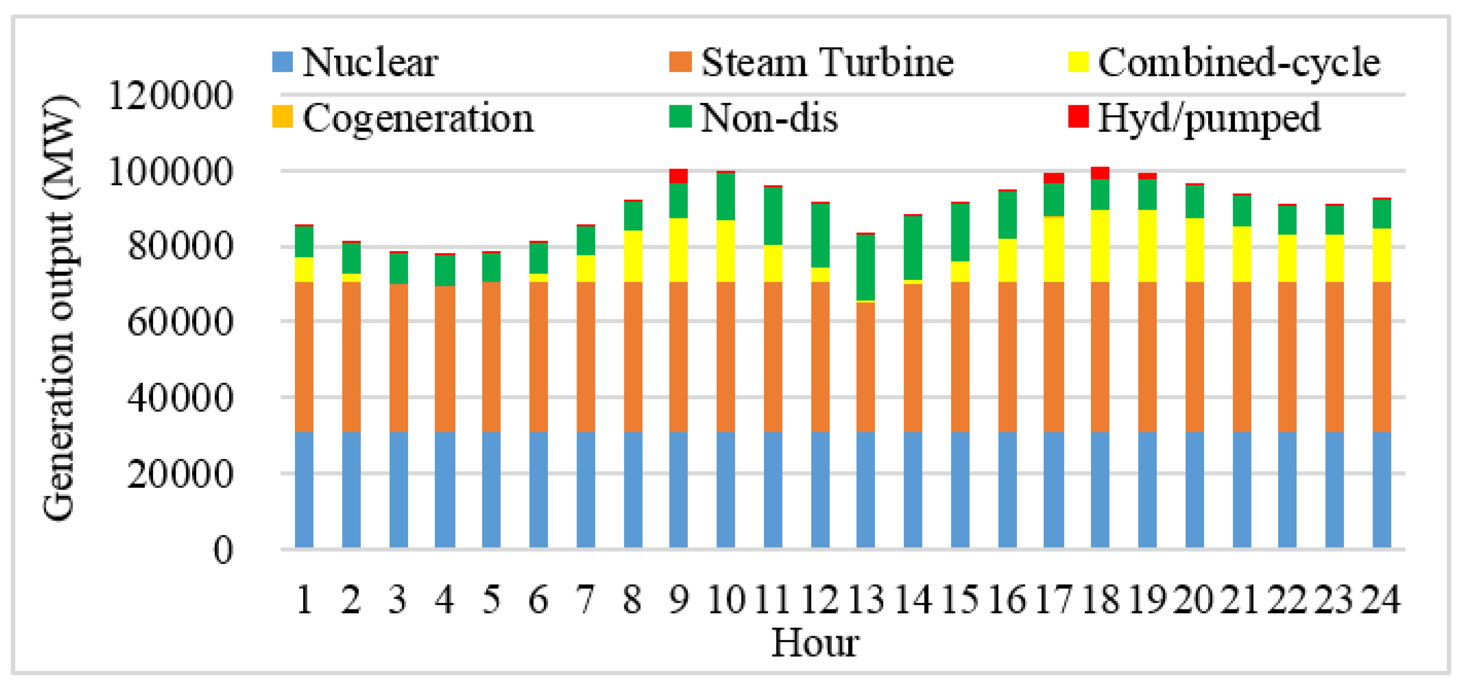
On the peak-load day in 2016, the available capacity of the dispatchable units, excluding those with scheduled maintenance and failed units, is 86,297 MW. Figure 1 shows the generation schedule for the peak-load day in 2016, where “Hyd/pumped” and “Non-dis” are the abbreviations for “hydraulic/pumped hydraulic unit” and “non-dispatchable unit”, respectively. The combined-cycle units covered the net-load variation and Hyd/pumped units are used for peak shaving.
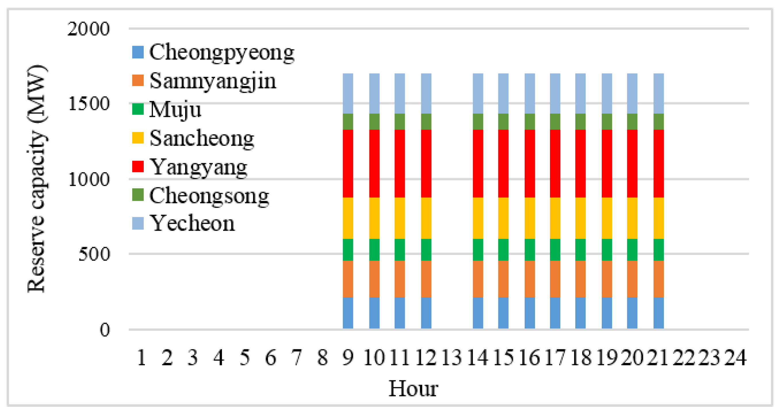
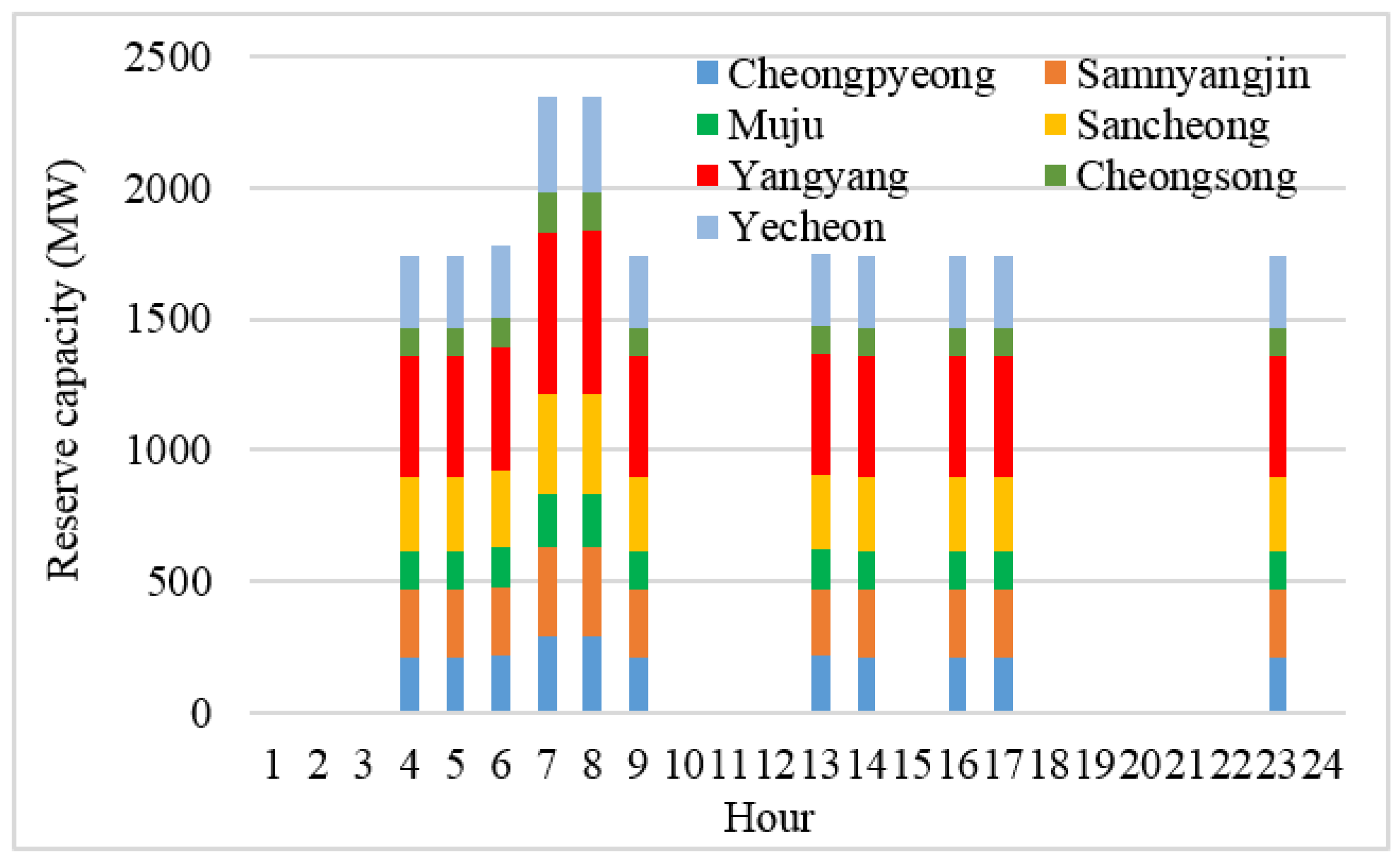
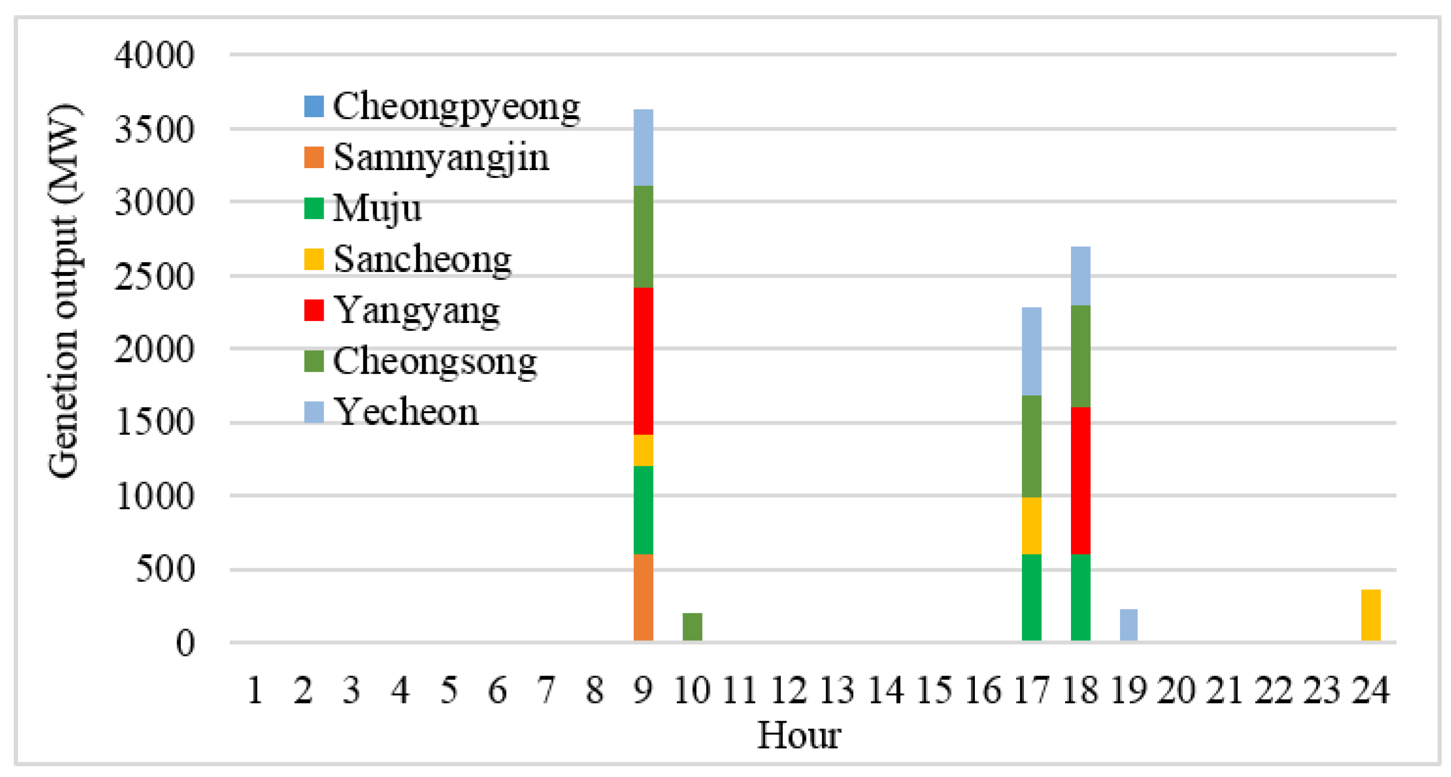
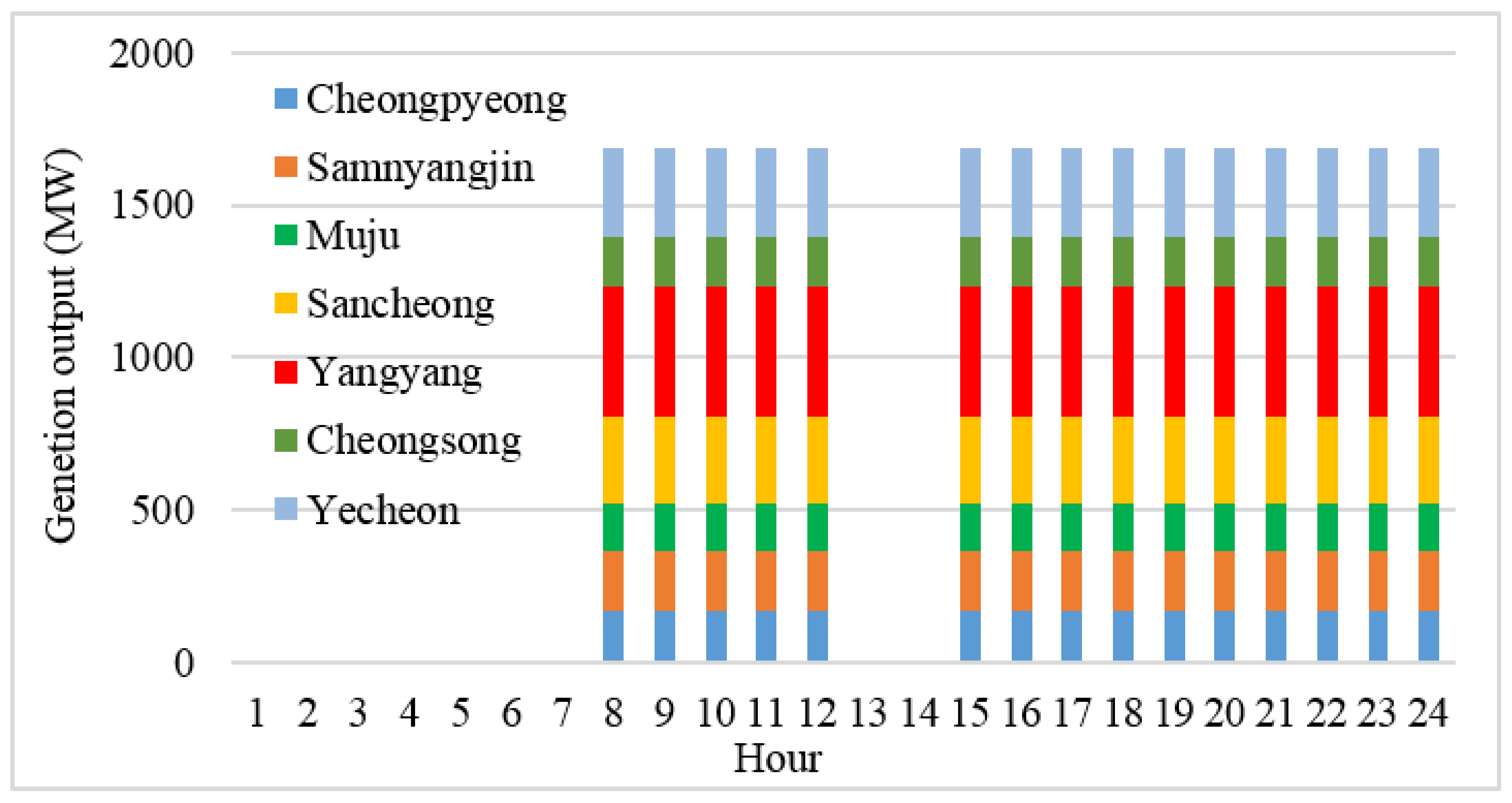
First, the 12 h supply period, i.e., hours 9–12 and 14–21, was calculated using the uniform allocation method. The Pi,t−Δt for every PHES is shown in Figure 2. The EPi, ∑Pi,t−Δt, REPi, and REP are provided in Table 5; the EPi is given as the maximum available energy in Table 1, and the REPi was calculated using Equation (7). The hourly reserve capacity for every PHES, i.e., RCPi,t, is shown in Figure 3. The calculated RSE using this method is 9.8119 [hours/day].
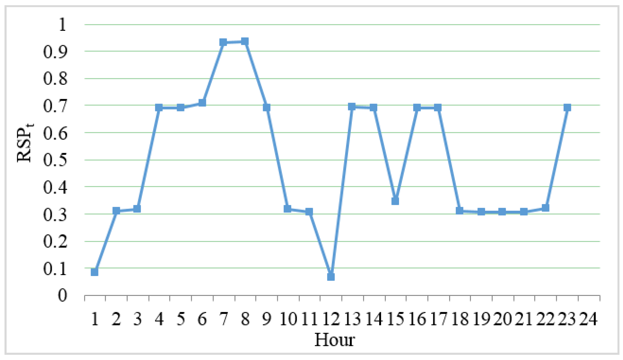
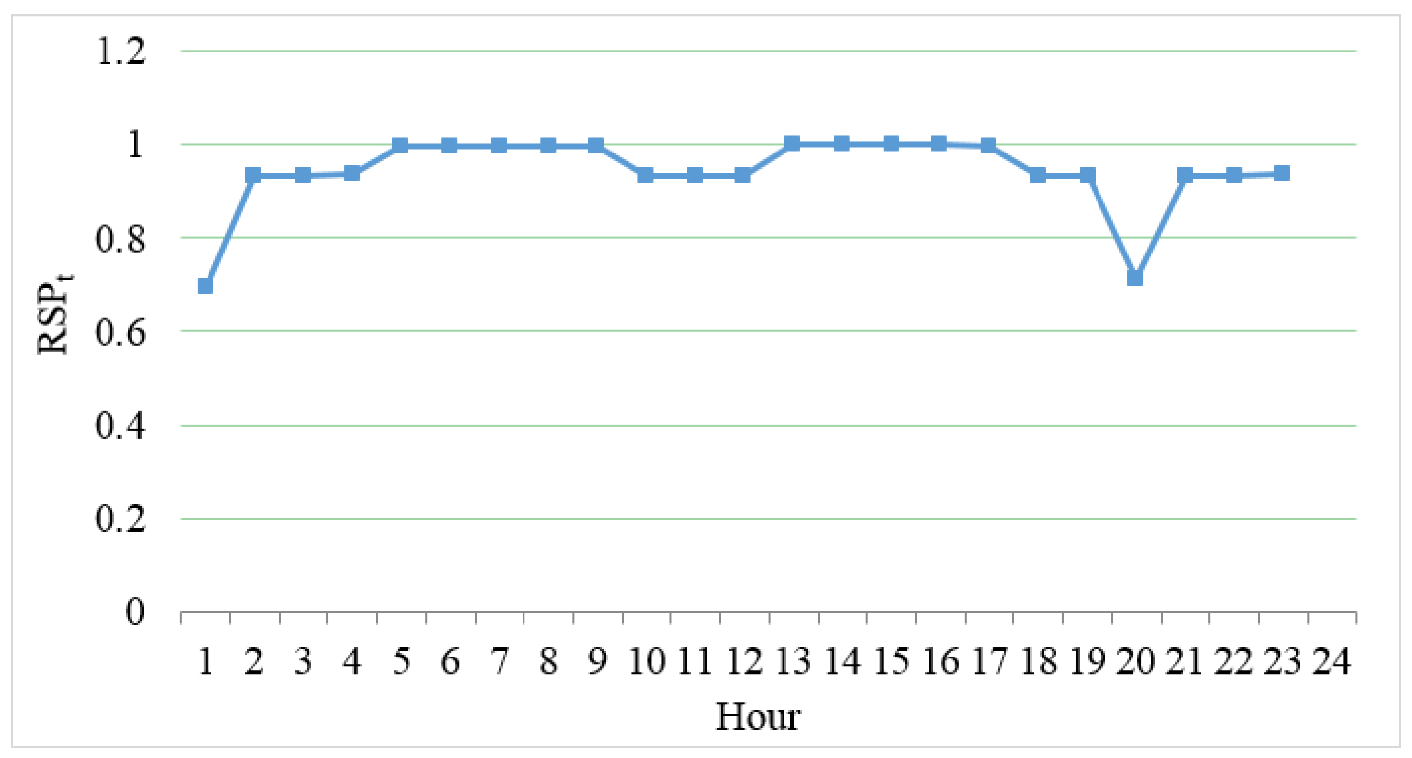
Based on the generation schedule, the RSPt is shown in Figure 4. The average RSPt value is 0.4966; the supply period of the proposed method is 15 h, i.e., hours 4–9, 13, 14, 16, 17, and 23. Using Equation (9), the RCPi,t for every PHES was computed, and the result is shown in Figure 5. The RSE is 9.3748 [hours/day], which is 4.45% smaller than that found from the uniform allocation method; the improvement of flexibility is confirmed by the decrease in RSE.
4.3. Result for the Peak-Load Day in 2029
The goal of this simulation is to examine the effect of the proposed reserve scheduling under the high VG penetration level. The VG penetration level in 2029 is planned to increase to 22%. For reference, the VG penetration level is approximately 3.6% in 2016. Under the assumption that the installed capacities of renewable energy resources are proportionally increased to their planned capacity for 2029, the output patterns of the VG and non-VG on the peak day in 2029 are adjusted to be the same as that in 2016. The technical information of newly installed generators from 2017 to 2029 is assumed to be the same as that of the latest generators (refer to [16] for more details). The available capacity of dispatchable units is 116,712 MW. Figure 6 shows the generation schedule for the peak-load day in 2029.
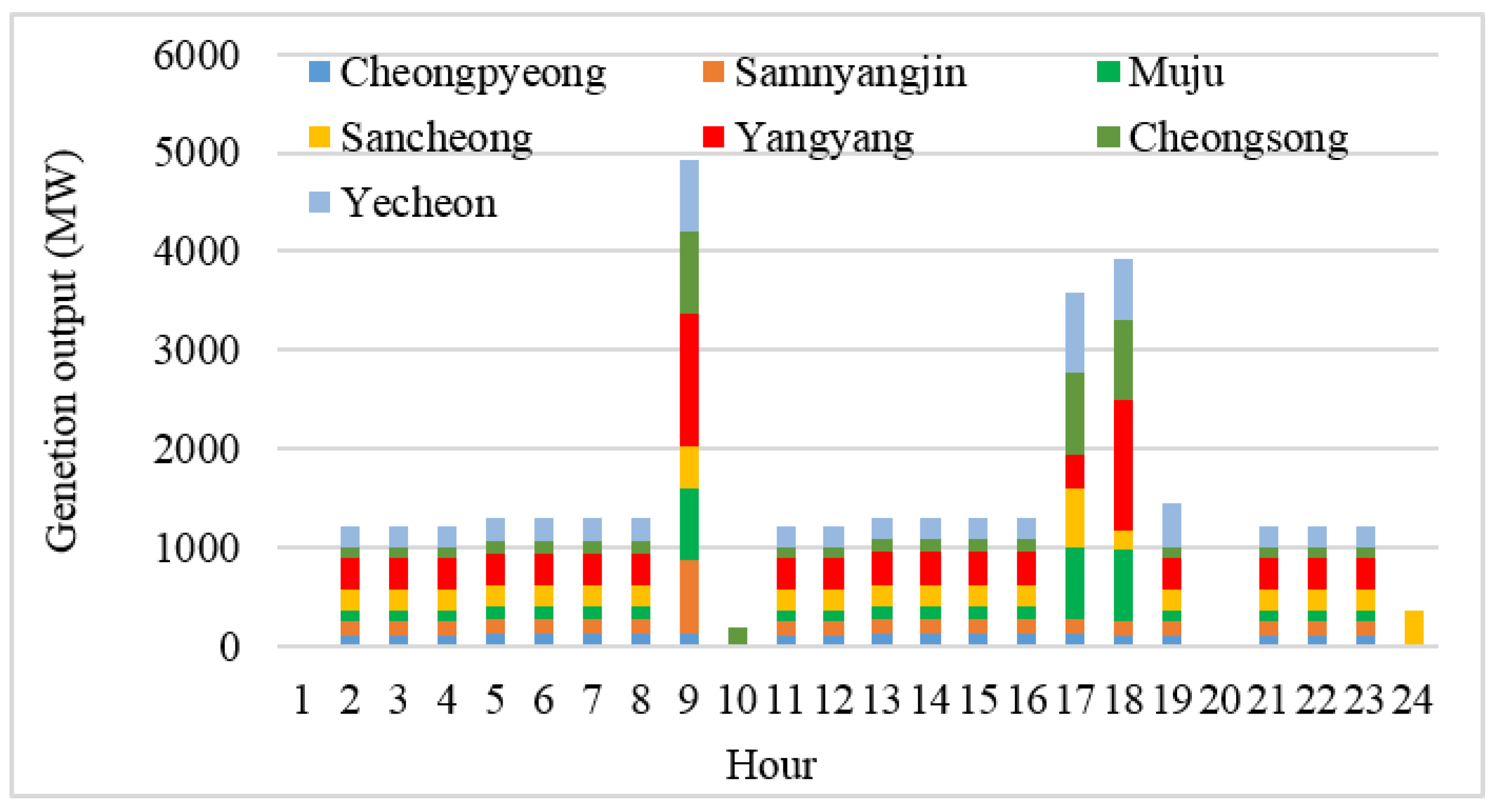
The 15 h supply period, i.e., hours 8–12 and 15–24, was computed using the uniform allocation method. Figure 7 shows the Pi,t−Δt for each PHES. Table 6 lists the EPi, ∑Pi,t−Δt, REPi, and REP. Figure 8 shows the hourly reserve capacity for every PHES, i.e., RCPi,t. The RSE value from the uniform allocation method is 20.7691 [hours/day].
Figure 9 shows the RSPt value. The RCPi,t for every PHES was computed, and the result is shown in Figure 10. The RSE is 20.5875 [hours/day], which is 0.9% smaller than the result from the uniform allocation method. In the case of small VG penetration level (i.e., 2016), the effect of the proposed method on the flexibility improvement is larger than that of the uniform allocation method. It may be mainly because the ratio of PHES to the available capacity in 2029 is smaller than that in 2016.
5. Conclusions
This study proposed a flexibility-based reserve scheduling method for PHES. In this method, the flexibility is quantified using a risk index, termed the ramping capability shortage expectation (RSE). The PHES reserve energy is allocated to each hour in proportion to the RSPt. The peak-load days for 2016 and 2029 were selected to examine the applicability and performance of the proposed method. We compared the difference in flexibility between the previous and proposed methods. The results show that the flexibility for the peak-load days in 2016 and in 2029 can be improved by 4.45% and 0.9%, respectively. In the future, more improvements could be made by examining the impact of other flexible resources on flexibility. It would be also interesting to examine the effect of the co-optimization of reserve and energy scheduling on the flexibility.
Acknowledgments
This research was supported by the Korea Electric Power Corporation through the Korea Electrical Engineering & Science Research Institute (grant number: R15XA03-55) and Basic Science Research Program through the National Research Foundation of Korea (NRF) funded by the Ministry of Education (2017R1D1A1B03029308).
Author Contributions
Chang-Gi Min conducted the main body of research and Mun-Kyeom Kim reviewed the work continuously.
Conflicts of Interest
The authors declare no conflict of interest.
Nomenclature
| Ai,t | Random variable representing availability of unit i at time t (1 if available, 0 otherwise) |
| c | Element of Ct−Δt |
| Ct−Δt | Set of combination of Ai,t−Δt when Oi,t−Δt is non-zero for all i |
| e | Element of Et−Δt |
| Et−Δt | Set of NLFEt |
| EPi | PHES i’s total energy at a given water level |
| FNLt | Forecast net load at time t |
| i | Index of generating unit |
| I | Set of generating unit |
| LFEt | Random variable representing load forecast error at time t |
| NLFEt | Random variable representing net load forecast error at time t |
| Oi,t | Value representing whether unit i is on-line at time t (1 if online, 0 otherwise) |
| Pi,t | Generation output of unit i at time t |
| Pmax,i | Maximum generation level of unit i |
| PHESi | Pumped hydroelectric storage i |
| Probc[·] | Probability in the brackets. |
| Probc[·] | Probability of c if condition [∙] is satisfied, 0 otherwise. |
| RCPi,t | Reserve capacity of PHESi at time t |
| RCRt | Ramping capability requirement at time t |
| REP | Reserve energy of all PHESs |
| REPi | Reserve energy of PHESi |
| rri | Ramp rate of unit i |
| RSPt | Ramping capability shortage probability at time t |
| SRCt | System ramping capability at time t |
| t, t’ | Index of time |
| Ts | Length of supply period |
| Δt | Minimum time interval between operating points |
| VG | Variable generation |
| VGFEt | Random variable representing variable generation forecast error at time t |
References
- Deobooleoh Democratic Party. Presidential Election Pledge. Available online: http://theminjoo.kr/autoalbum/page/minjoo/view.html?extweb=true (accessed on 20 August 2017).
- The Ministry of Trade, Industry and Energy. The 4th New & Renewable Energy Basic Plan; MOTIE: Sejong-si, Korea, 2014.
- Lund, P.D.; Lindgren, J.; Mikkola, J.; Salpakari, J. Review of energy system flexibility measures to enable high levels of variable renewable electricity. Renew. Sustain. Energy Rev. 2015, 45, 785–807. [Google Scholar] [CrossRef]
- Pérez-Díaz, J.I.; Jiménez, J. Contribution of a pumped-storage hydropower plant to reduce the scheduling costs of an isolated power system with high wind power penetration. Energy 2016, 109, 92–104. [Google Scholar] [CrossRef]
- Ming, Z.; Kun, Z.; Daoxin, L. Overall review of pumped-hydro energy storage in China: Status quo, operation mechanism and policy barriers. Renew. Sustain. Energy Rev. 2013, 17, 35–43. [Google Scholar] [CrossRef]
- Deane, J.; McKeogh, E.; Gallachoir, B. Derivation of intertemporal targets for large pumped hydro energy storage with stochastic optimization. IEEE Trans. Power Syst. 2013, 28, 2147–2155. [Google Scholar] [CrossRef]
- Pavesi, G.; Cavazzini, G.; Ardizzon, G. Numerical analysis of the transient behaviour of a variable speed pump-turbine during a pumping power reduction scenario. Energies 2016, 9, 534. [Google Scholar] [CrossRef]
- Korea Power Exchange. The PHES Operation Strategy Considering Power System Reliability; KPX: Naju-si, Korea, 2013. [Google Scholar]
- Yao, E.; Wang, H.; Liu, L.; Xi, G. A novel constant-pressure pumped hydro combined with compressed air energy storage system. Energies 2014, 8, 154–171. [Google Scholar] [CrossRef]
- Deane, J.P.; Gallachóir, B.Ó.; McKeogh, E. Techno-economic review of existing and new pumped hydro energy storage plant. Renew. Sustain. Energy Rev. 2010, 14, 1293–1302. [Google Scholar] [CrossRef]
- Borges, C.L.; Pinto, R.J. Small hydro power plants energy availability modeling for generation reliability evaluation. IEEE Trans. Power Syst. 2008, 23, 1125–1135. [Google Scholar] [CrossRef]
- Shim, K.; Kim, S.; Lee, J.; Choi, E.; Choi, J. Detection of low-frequency oscillation using synchrophasor in wide-area rolling blackouts. Int. J. Electr. Power Energy Syst. 2014, 63, 1015–1022. [Google Scholar] [CrossRef]
- The Korean Institute of Electrical Engineers. An Investigation Report on a Rolling Blackout Accident on Sep. 15, 2011 in Korea; KIEE: Seoul, Korea, 2011. [Google Scholar]
- Organization for Cross-regional Coordination of Transmission Operator. The Electricity Supply and Demand Plan. Available online: https://www.occto.or.jp/kyoukei/teishutsu/files/kaisetu.pdf (accessed on 15 September 2017).
- Korea Power Exchange. Electricity Market. Operation Rules; KPX: Naju-si, Korea, 2017. [Google Scholar]
- The Ministry of Trade, Industry and Energy. The 7th Basic Plan on Electricity Demand and Supply; MOTIE: Sejong-si, Korea, 2015.
- Black, M.; Strbac, G. Value of bulk energy storage for managing wind power fluctuations. IEEE Trans. Energy Convers. 2007, 22, 197–205. [Google Scholar] [CrossRef]
- Borghetti, A.; D’Ambrosio, C.; Lodi, A.; Martello, S. An MILP approach for short-term hydro scheduling and unit commitment with head-dependent reservoir. IEEE Trans. Power Syst. 2008, 23, 1115–1124. [Google Scholar] [CrossRef]
- Kazempour, S.J.; Moghaddam, M.P.; Haghifam, M.; Yousefi, G. Risk-constrained dynamic self-scheduling of a pumped-storage plant in the energy and ancillary service markets. Energy Convers. Manag. 2009, 50, 1368–1375. [Google Scholar] [CrossRef]
- Varkani, A.K.; Daraeepour, A.; Monsef, H. A new self-scheduling strategy for integrated operation of wind and pumped-storage power plants in power markets. Appl. Energy 2011, 88, 5002–5012. [Google Scholar] [CrossRef]
- Pérez-Díaz, J.I.; Chazarra, M.; García-González, J.; Cavazzini, G.; Stoppato, A. Trends and challenges in the operation of pumped-storage hydropower plants. Renew. Sustain. Energy Rev. 2015, 44, 767–784. [Google Scholar] [CrossRef]
- Min, C.; Park, J.; Hur, D.; Kim, M. A risk evaluation method for ramping capability shortage in power systems. Energy 2016, 113, 1316–1324. [Google Scholar] [CrossRef]
- Wang, Q.; Hodge, B.-M. Enhancing power system operational flexibility with flexible ramping products: A review. IEEE Trans. Ind. Inf. 2016, 13, 1652–1664. [Google Scholar] [CrossRef]
- Billinton, R.; Allan, R. Reliability Evaluation of Power Systems, 2nd ed.; Springer Science & Business Media: New York, NY, USA, 2013. [Google Scholar]
- Chazarra, M.; Pérez-Díaz, J.I.; García-González, J. Deriving optimal end of day storage for pumped-storage power plants in the joint energy and reserve day-ahead scheduling. Energies 2017, 10, 813. [Google Scholar] [CrossRef]
- Korea Power Exchange. Electric Power Statistics Information System. Available online: http://epsis.kpx.or.kr/epsis/ekesStaticMain.do?cmd=001001&flag=&locale=EN (accessed on 20 August 2017).
- Chung, M.; Lee, S.G.; Park, C.; Park, H.-C.; Im, Y.-H. Development of a combined energy-demands calculator for urban building communities in Korea. Environ. Plan. B 2013, 40, 289–310. [Google Scholar] [CrossRef]
- Master’s Space. M-Core User’s Manual; MS: Anyang-si, Korea, 2016. [Google Scholar]
- Li, L. Matlab User Manual; Matlab: Natick, MA, USA, 2001. [Google Scholar]
Figure 1.
The calculated generation schedule for the peak-load day in 2016.

Figure 2.
PHES Pi,t−Δt for the peak-load day in 2016.
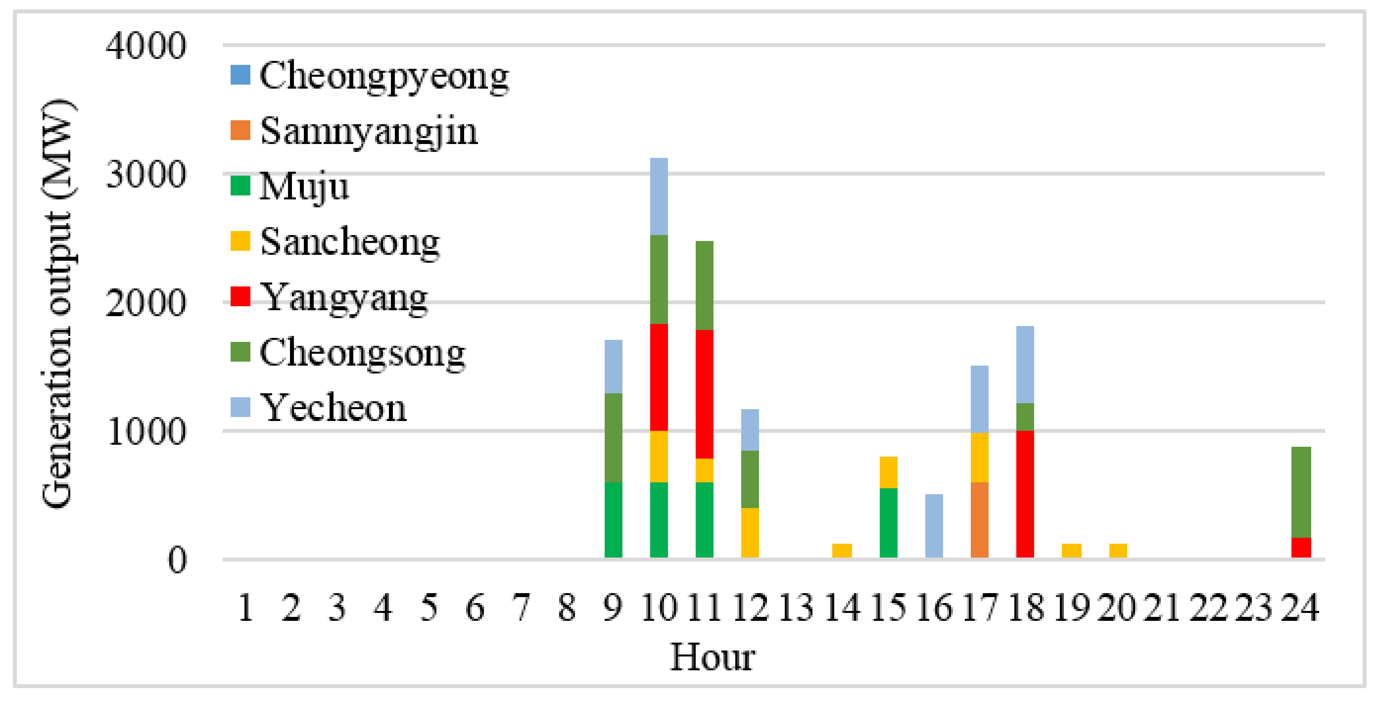
Figure 3.
RCPi,t using the uniform allocation method for 2016.

Figure 4.
RSPt on the peak-load day in 2016.

Figure 5.
Hourly reserve capacity in 2016 based on the proposed method.

Figure 6.
The calculated generation schedule for the peak-load day in 2029.

Figure 7.
PHES Pi,t−Δt for the peak-load day in 2029.

Figure 8.
RCPi,t using the uniform allocation method for 2029.

Figure 9.
RSPt on the peak-load day in 2029.

Figure 10.
Hourly reserve capacity in 2029 based on the proposed method.

Table 1.
Basic pumped hydroelectric storage (PHES) information in Korea.
| Name | Generation Power (MW) | Energy at Full Water Level (MWh) | Energy at Minimum Water Level (MWh) | Maximum Available Energy (MWh) |
|---|---|---|---|---|
| Cheongpyeong | 200 × 2 | 2680 | 168.7 | 2511.3 |
| Samnyangjin | 360 × 2 | 3900 | 320.6 | 3579.4 |
| Muju | 300 × 2 | 4440 | 336.6 | 4103.4 |
| Sancheong | 350 × 2 | 5670 | 393.4 | 5276.6 |
| Yangyang | 260 × 4 | 8500 | 128.9 | 8371.1 |
| Cheongsong | 300 × 2 | 5100 | 360.3 | 4739.7 |
| Yecheon | 400 × 2 | 6580 | 434 | 6146.0 |
Table 2.
PHES hourly reserve capacity. 10% of the maximum available energy is allocated based on the uniform allocation method (unit: MWh).
Table 2.
PHES hourly reserve capacity. 10% of the maximum available energy is allocated based on the uniform allocation method (unit: MWh).
| Hour | Cheong -Pyeong | Samnyang-Jin | Muju | Sancheong | Yangyang | Cheong -Song | Yecheon |
|---|---|---|---|---|---|---|---|
| Hour 1 | 20.93 | 29.83 | 34.20 | 43.97 | 69.76 | 39.50 | 51.22 |
| Hour 2 | 20.93 | 29.83 | 34.20 | 43.97 | 69.76 | 39.50 | 51.22 |
| Hour 3 | 20.93 | 29.83 | 34.20 | 43.97 | 69.76 | 39.50 | 51.22 |
| Hour 4 | 20.93 | 29.83 | 34.20 | 43.97 | 69.76 | 39.50 | 51.22 |
| Hour 5 | 20.93 | 29.83 | 34.20 | 43.97 | 69.76 | 39.50 | 51.22 |
| Hour 6 | 20.93 | 29.83 | 34.20 | 43.97 | 69.76 | 39.50 | 51.22 |
| Hour 7 | 20.93 | 29.83 | 34.20 | 43.97 | 69.76 | 39.50 | 51.22 |
| Hour 8 | 20.93 | 29.83 | 34.20 | 43.97 | 69.76 | 39.50 | 51.22 |
| Hour 9 | 20.93 | 29.83 | 34.20 | 43.97 | 69.76 | 39.50 | 51.22 |
| Hour 10 | 20.93 | 29.83 | 34.20 | 43.97 | 69.76 | 39.50 | 51.22 |
| Hour 11 | 20.93 | 29.83 | 34.20 | 43.97 | 69.76 | 39.50 | 51.22 |
| Hour 12 | 20.93 | 29.83 | 34.20 | 43.97 | 69.76 | 39.50 | 51.22 |
| Total | 251.13 | 357.94 | 410.34 | 527.66 | 837.11 | 473.97 | 614.60 |
Table 3.
RSPt values for the numerical example
| t (h) | 1 | 2 | 3 | 4 | 5 | 6 | 7 | 8 | 9 | 10 | 11 | 12 |
| RSPt | 0.1 | 0.1 | 0.2 | 0.2 | 0.3 | 0.3 | 0.4 | 0.4 | 0.5 | 0.5 | 0.6 | 0.6 |
| t (h) | 13 | 14 | 15 | 16 | 17 | 18 | 19 | 20 | 21 | 22 | 23 | 23 |
| RSPt | 0.6 | 0.6 | 0.5 | 0.5 | 0.4 | 0.4 | 0.3 | 0.3 | 0.2 | 0.2 | 0.1 | 0.1 |
Table 4.
PHES hourly reserve capacity. 10% of the maximum available energy is allocated based on the proposed method (unit: MWh).
Table 4.
PHES hourly reserve capacity. 10% of the maximum available energy is allocated based on the proposed method (unit: MWh).
| Hour | Cheong -Pyeong | Samnyang -Jin | Muju | Sancheong | Yangyang | Cheong -Song | Yecheon |
|---|---|---|---|---|---|---|---|
| Hour 7 | 16.74 | 23.86 | 27.36 | 35.18 | 55.81 | 31.60 | 40.97 |
| Hour 8 | 16.74 | 23.86 | 27.36 | 35.18 | 55.81 | 31.60 | 40.97 |
| Hour 9 | 20.93 | 29.83 | 34.20 | 43.97 | 69.76 | 39.50 | 51.22 |
| Hour 10 | 20.93 | 29.83 | 34.20 | 43.97 | 69.76 | 39.50 | 51.22 |
| Hour 11 | 25.11 | 35.79 | 41.03 | 52.77 | 83.71 | 47.40 | 61.46 |
| Hour 12 | 25.11 | 35.79 | 41.03 | 52.77 | 83.71 | 47.40 | 61.46 |
| Hour 13 | 25.11 | 35.79 | 41.03 | 52.77 | 83.71 | 47.40 | 61.46 |
| Hour 14 | 25.11 | 35.79 | 41.03 | 52.77 | 83.71 | 47.40 | 61.46 |
| Hour 15 | 20.93 | 29.83 | 34.20 | 43.97 | 69.76 | 39.50 | 51.22 |
| Hour 16 | 20.93 | 29.83 | 34.20 | 43.97 | 69.76 | 39.50 | 51.22 |
| Hour 17 | 16.74 | 23.86 | 27.36 | 35.18 | 55.81 | 31.60 | 40.97 |
| Hour 18 | 16.74 | 23.86 | 27.36 | 35.18 | 55.81 | 31.60 | 40.97 |
| Total | 251.13 | 357.94 | 410.34 | 527.66 | 837.11 | 473.97 | 614.60 |
Table 5.
EPi and Pi,t−Δt on the peak-load day in 2016.
| PHES Name | EPi (MWh) | ∑Pi,t−Δt (MW) | REPi (MWh) |
|---|---|---|---|
| Cheongpyeong | 2511.3 | 0 | 2511.3 |
| Samnyangjin | 3579.4 | 600 | 2979.4 |
| Muju | 4103.4 | 2356 | 1747.4 |
| Sancheong | 5276.6 | 1968 | 3308.6 |
| Yangyang | 8371.1 | 3000 | 5371.1 |
| Cheongsong | 4739.7 | 3460 | 1279.7 |
| Yecheon | 6146.0 | 2974 | 3172.0 |
| - | - | - | REP: 20,369.5 (MWh) |
Table 6.
EPi and Pi,t−Δt on the peak-load day in 2029.
| PHES Name | EPi (MWh) | ∑Pi,t−Δt (MW) | REPi (MWh) |
|---|---|---|---|
| Cheongpyeong | 2511.3 | 0 | 2511.3 |
| Samnyangjin | 3579.4 | 600 | 2979.4 |
| Muju | 4103.4 | 1800 | 2303.4 |
| Sancheong | 5276.6 | 959.4 | 4317.2 |
| Yangyang | 8371.1 | 2000 | 6371.1 |
| Cheongsong | 4739.7 | 2300 | 2439.7 |
| Yecheon | 6146.0 | 1735.4 | 4410.6 |
| - | - | - | REP: 25,332.8 (MWh) |
© 2017 by the authors. Licensee MDPI, Basel, Switzerland. This article is an open access article distributed under the terms and conditions of the Creative Commons Attribution (CC BY) license (http://creativecommons.org/licenses/by/4.0/).
Share and Cite
MDPI and ACS Style
Min, C.-G.; Kim, M.-K. Flexibility-Based Reserve Scheduling of Pumped Hydroelectric Energy Storage in Korea. Energies 2017, 10, 1478. https://doi.org/10.3390/en10101478
AMA Style
Min C-G, Kim M-K. Flexibility-Based Reserve Scheduling of Pumped Hydroelectric Energy Storage in Korea. Energies. 2017; 10(10):1478. https://doi.org/10.3390/en10101478
Chicago/Turabian StyleMin, Chang-Gi, and Mun-Kyeom Kim. 2017. "Flexibility-Based Reserve Scheduling of Pumped Hydroelectric Energy Storage in Korea" Energies 10, no. 10: 1478. https://doi.org/10.3390/en10101478
Note that from the first issue of 2016, this journal uses article numbers instead of page numbers. See further details here.