Article

Energy Performance and Radial Force of a Mixed-Flow Pump with Symmetrical and Unsymmetrical Tip Clearances

State Key Laboratory of Hydroscience and Engineering, Tsinghua University, Beijing 100084, China
*
Author to whom correspondence should be addressed.
Energies 2017, 10(1), 57; https://doi.org/10.3390/en10010057
Submission received: 26 October 2016 / Revised: 28 December 2016 / Accepted: 29 December 2016 / Published: 5 January 2017

Abstract

:
The energy performance and radial force of a mixed flow pump with symmetrical and unsymmetrical tip clearance are investigated in this paper. As the tip clearance increases, the pump head and efficiency both decrease. The center of the radial force on the principal axis is located at the coordinate origin when the tip clearance is symmetrical, and moves to the third quadrant when the tip clearance is unsymmetrical. Analysis results show that the total radial force on the principal axis is closely related to the fluctuation of mass flow rate in each single flow channel. Unsteady simulations show that the dominant frequencies of radial force on the hub and blade correspond to the blade number, vane number, or double blade number because of the rotor stator interaction. The radial force on the blade pressure side decreases with the tip clearance increase because of leakage flow. The unsymmetrical tip clearances in an impeller induce uneven leakage flow rate and then result in unsymmetrical work ability of each blade and flow pattern in each channel. Thus, the energy performance decreases and the total radial force increases for a mixed flow pump with unsymmetrical tip clearance.

1. Introduction

Mixed-flow pumps are important devices with the advantage of a wide, high-efficiency operating region; these pumps are widely used in hydraulic engineering, petrochemical engineering, power supply, agricultural irrigation and other fields [1]. The impeller is the key component that performs energy conversion and exerts a marked effect on pump performance [2,3]. Turbulent flow in an impeller is highly complicated especially when there is blade tip clearance. The blade tip clearance is the gap between the blade tip and impeller shroud and is indispensable because of the impeller rotation. The extent of tip clearance is extremely small, usually 0.1–2 mm; however, this tip clearance causes leakage flow and vortex motion, which directly affect the flow of nearly 50% of the area in the impeller passage and thereby affect the efficiency and stability of the impeller.
Flow phenomena owing to blade tip clearance are extremely complicated and involve leakage flow, vortex shedding and cavitation. Gearhart [4] investigated the effect of tip clearance configuration on the flow pattern and cavitation performance of a turbomachine and found that a slightly divergent gap configuration provided poor gap cavitation performance. Laborde et al. [5] proposed an optimum clearance geometry by rounding the blade pressure side to eliminate clearance cavitation. You et al. [6] used a large eddy simulation to study the vortex structures, dynamics and associated low-pressure regions in tip clearance, and found that the end-wall groove can suppress tip leakage vortex. Wu et al. [7,8,9,10] performed a series of experiments by using particle image velocimetry measurements to study the flow structures in the tip region of a water-jet pump rotor, including the tip clearance flow, tip leakage vortex and cavitation flow; they found that the tip leakage vortex started to form near the suction-side edge of a blade tip and appeared as a swirling jet, migrating to the middle of the blade passage. The backward leakage flow penetrated into the passage and created a shear layer in the interface with the main flow. Zhang et al. [11,12,13] numerically and experimentally investigated the tip leakage cavitation pattern flow, including tip leakage vortex cavitation, tip corner vortex cavitation, shear layer cavitation, and blowing cavitation in an axial flow pump. The results showed that the low pressure in the corner vortex and the jet shear layer with high velocity were essential mechanisms for tip clearance cavitation. Owing to the complex flow pattern in tip clearance and its effect on the main flow in blade-to-blade passage, the characteristics of radial force are substantially influenced by tip clearance. Therefore, the relationship between tip clearance and radial force should be investigated in the present study.
Given the rotor stator interaction, the flow in the impeller is unsteady with secondary flow, jet wake, back flow, impact flow, and so on [14,15,16,17]. The unsteady flow in the impeller consequently induces uneven radial force. The radial force causes the vibration of the principal axis of the pump, and significantly affects the operational stability of pumps. Numerous studies investigated the characteristics of radial force theoretically, experimentally and numerically. Guo and Okamoto [18] simultaneously measured the radial fluid force acting on impellers, pressure fluctuations in volute and vibration of the shaft, and revealed their relationship under the rotor-stator interaction. Rodriguez et al. [19] conducted theoretical analysis on frequency and amplitude of non-uniform fluid radial force for centrifugal pumps, and analyzed the relationship between dominant frequency and the number of blades and guide vanes, and the sequence of interaction. Suzuki et al. [20] examined the characteristics of the rotor-dynamic fluid forces on the impeller, measured rotor-dynamic fluid forces in cases with and without whirling motion, and found that the rotor-dynamic forces become destabilizing in a wide range of positive whirls. Barrio et al. [21,22] studied the fluid-dynamic pulsations and the corresponding dynamic forces generated in a centrifugal pump with different outlet diameters due to blade volute interaction. They also estimated the dynamic radial forces and torque at the blade-passing frequency as a function of flow rate and blade-tongue radial gap, and determined that the dynamic load increased for off-design conditions. In rotating machinery, rotor-stator interaction is the main cause of operating instability. Most previous studies focused on radial force and rotor-stator interaction without considering of effect of tip clearance. Therefore, a comprehensive investigation of tip clearance, radial force, and rotor-stator interaction in a mixed-flow pump is needed.
The tip clearances mentioned in previous studies are all symmetrical; however, owing to the imperfect manufacturing accuracy and operating erosion, the tip clearances for different blades in an impeller are unsymmetrical. For a mixed flow pump, a blade with 2 mm tip clearance and other blades with 1 mm tip clearance are common when the pump runs for a certain time. Therefore, the characteristics of radial force for a mixed-flow pump with unsymmetrical tip clearance are investigated in the present study and compare with those without tip clearance and with symmetrical tip clearance.

2. Physical Model and Computational Domain

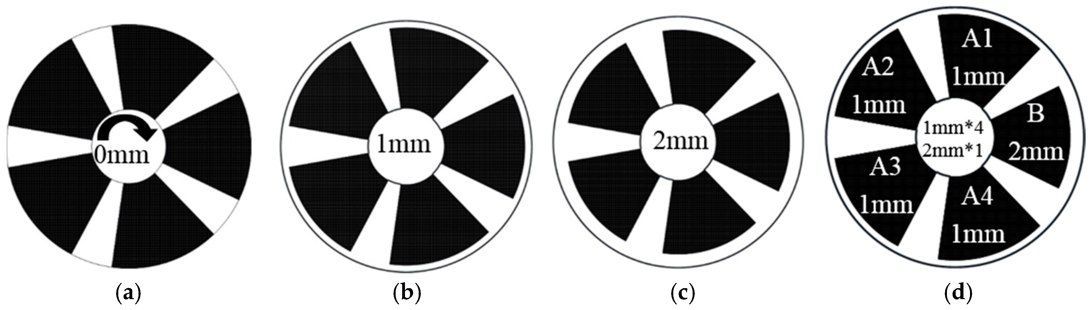
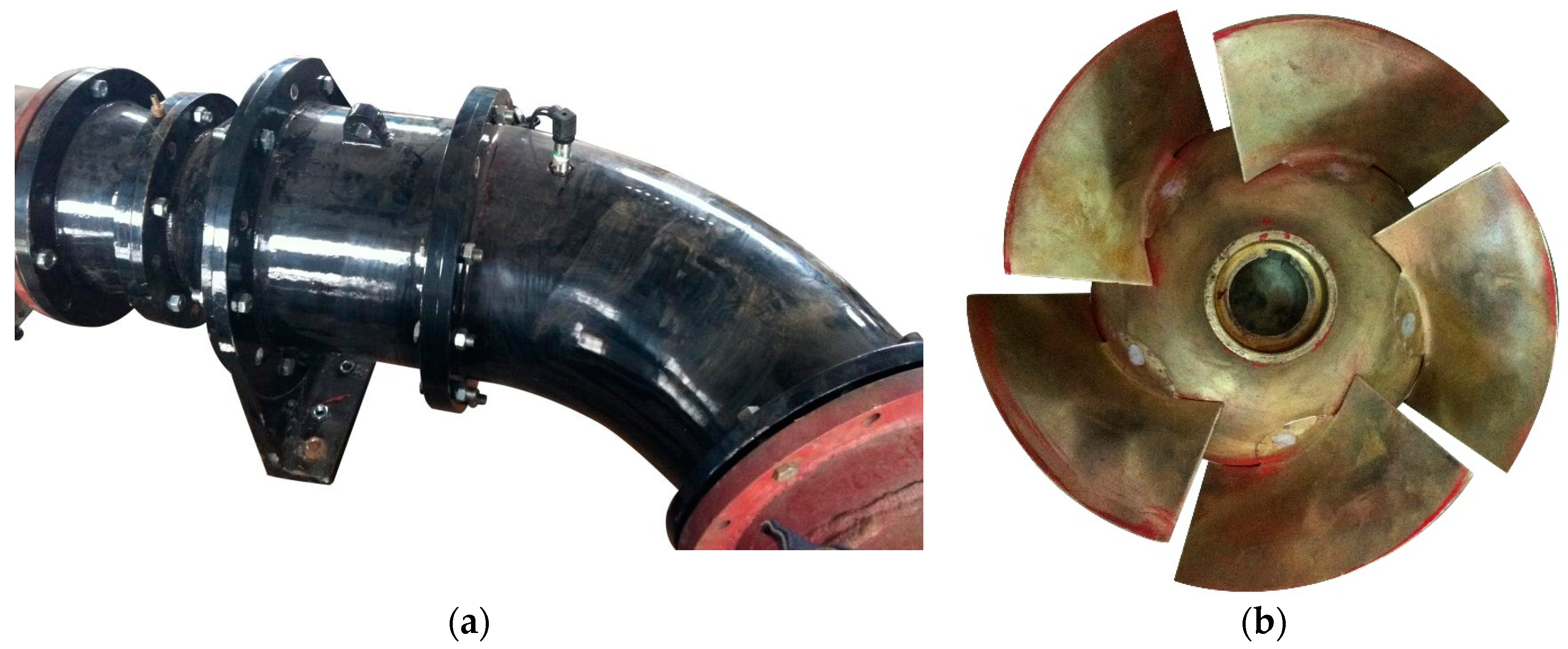
2.1. Parameters of the Mixed-Flow Pump

A single-stage mixed-flow pump with diffusers is investigated, and the design parameters are shown in Table 1. Figure 1 shows the pictures of the pump and impeller during experimental measurement.
Figure 2 shows the schematic of tip clearance types; (a–d) respectively indicate the impeller with 0 mm, 1 mm, 2mm, and unsymmetrical tip clearance. The impeller with unsymmetrical tip clearance includes 4 blades with 1mm tip clearance and 1 blade of 2 mm tip clearance.

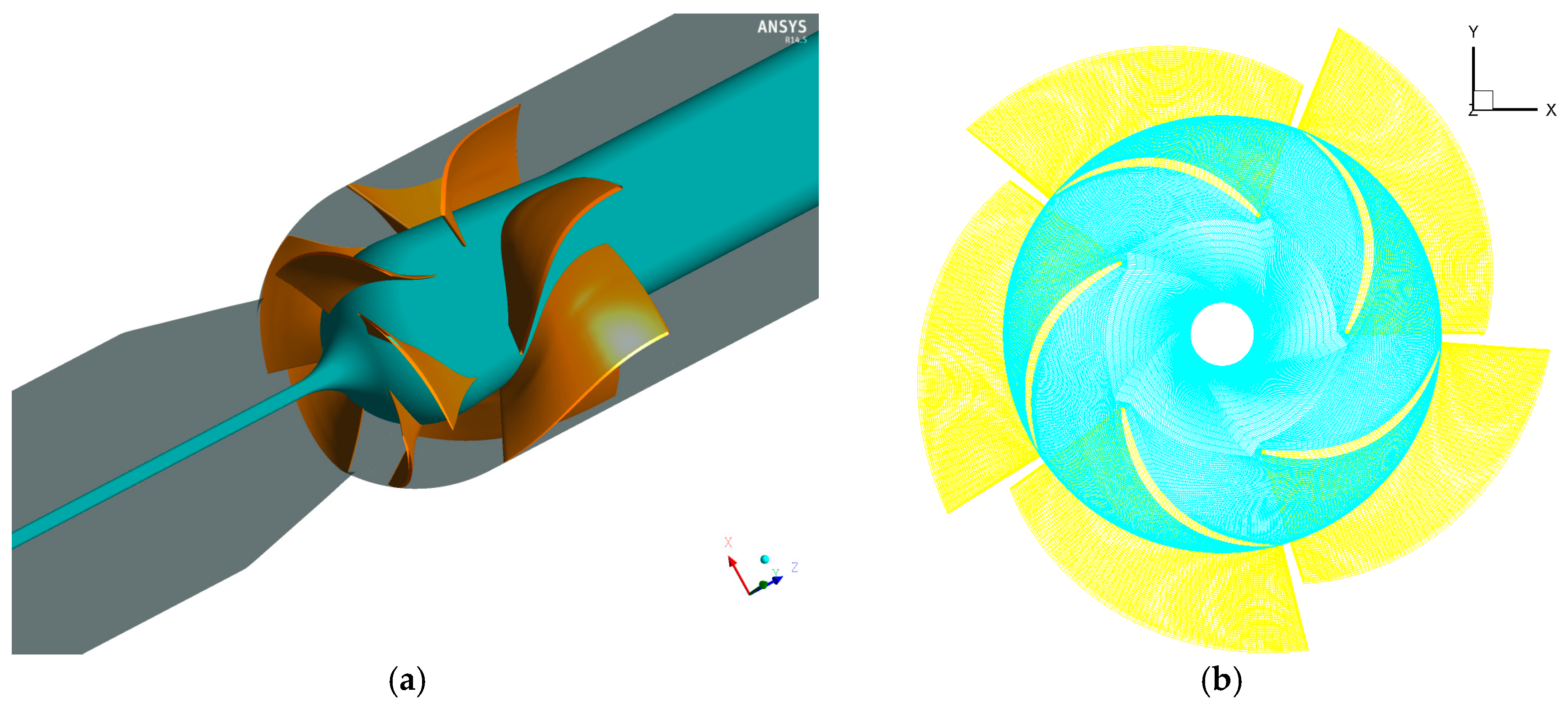
2.2. Computational Domain of the Mixed-Flow Pump

Figure 3 shows the computational domain and impeller mesh. To obtain high accuracy and capture unsymmetrical characteristics, the full computational domain is used, including inlet section, impeller, guide vane and outlet section, as shown in Figure 3a, and the inlet and outlet sections are lengthened to 5 times the pipe diameter in the present study. These sections are all meshed in structural hexahedral meshes, and the meshes near blade and guide vane surfaces are divided by O-block and then locally refined to get greater calculation accuracy. To study the radial force on the impeller, the force in of x and y directions of hub and blades is monitored, and the x and y directions are shown in Figure 3b.

3. Numerical Method and Settings

3.1. Mathematical Model and Method

Numerical simulation of the mixed flow pump is conducted by solving the Reynolds-Averaged Navier-Stokes equations with ANSYS CFX with the re-normalization group (RNG) k-ε model, which can accurately predict the rotating and curvature flow by making corrections to the model coefficients in the ε equation of standard k-ε turbulence model. The advantage of this method has been verified by Barrio et al. [22] and Tan et al. [23,24]. The no-slip boundary conditions are set at the flow near walls, and the pressure at the pump inlet and mass flow rate at the pump outlet are specified in accordance with the experimental measurement. To reduce the influence of inflow and outflow on the simulation, the inlet and outlet pipes are lengthened. The interfaces between the stationary and rotational domains are set by using frozen-rotor and transient rotor stator methods for steady and unsteady calculations, respectively.
In the steady calculation, the calculation is considered to be convergence when the root-mean-square residual is below 10−5. In the transient simulation, the timescale is determined by the rotation speed of the impeller, and three time steps; namely, 1.2931 × 10⁻⁴ s, 2.5862 × 10⁻⁴ s and 5.1724 × 10⁻⁴ s, are used to validate the independence of time step.

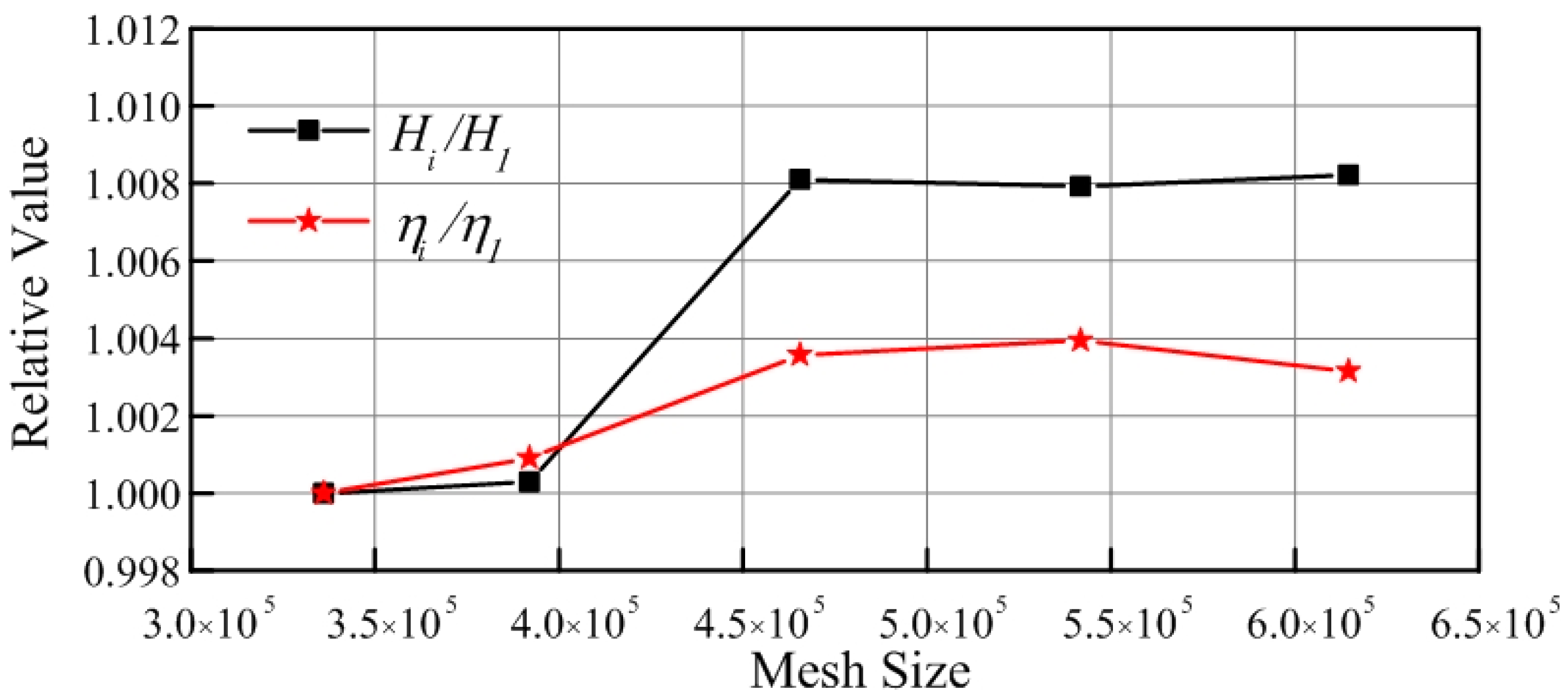
3.2. Mesh Independence Test

The meshes for the calculation domain are generated by ANSYS ICEM. In the simulation process, the grid number influences the calculation accuracy and computational efficiency. To validate the mesh element independence, 6 sets of meshes with elements from 3,732,680 to 5,558,720 are employed. In the mesh independence test, only the mesh number of the impeller is changed, and the mesh number of other parts are set as the fixed value according to experience. Figure 4 shows the influence of mesh elements on the calculation results. Evidently, the global performance shows variation with the increasing element number, but when the mesh number exceeds 4,500,000, the results show a slight difference. Therefore, the mesh containing 4,763,520 elements is selected as the final mesh in the following calculations.

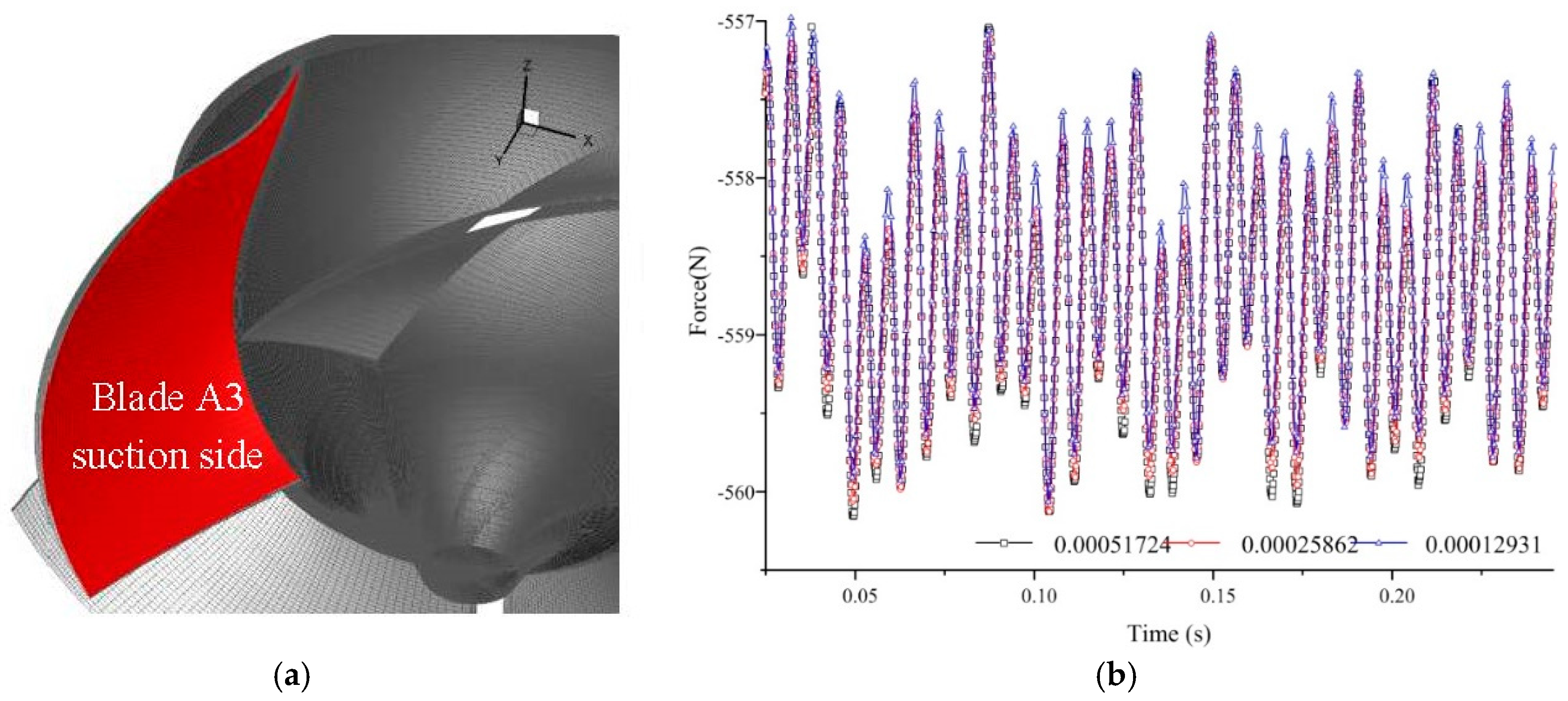
3.3. Time Step Independence Test

The influence of time step Δt on the evaluation of transient flow filed is also tested. Three different time steps, namely, 1.2931 × 10⁻⁴ s, 2.5862 × 10⁻⁴ s and 5.1724 × 10⁻⁴ s, which respond to 1/320, 1/160, and 1/80 of an impeller revolution T = 60/1450 = 0.414 s, are used in the calculation. Figure 5b shows the time histories of y-force component on blade A3 suction side for time steps of 1.2931 × 10⁻⁴ s, 2.5862 × 10⁻⁴ s and 5.1724 × 10⁻⁴ s. The location of blade A3 suction side is shown in Figure 5a. It can be observed that the fluctuation of force curves match perfectly at the y component force, which indicates that the influence of three time steps is negligible. Therefore, a time step of 2.5862 × 10⁻⁴ s was selected for transient calculation. Under this setting, the flow field is monitored 160 times in one revolution of the impeller.

4. Result and Discussion

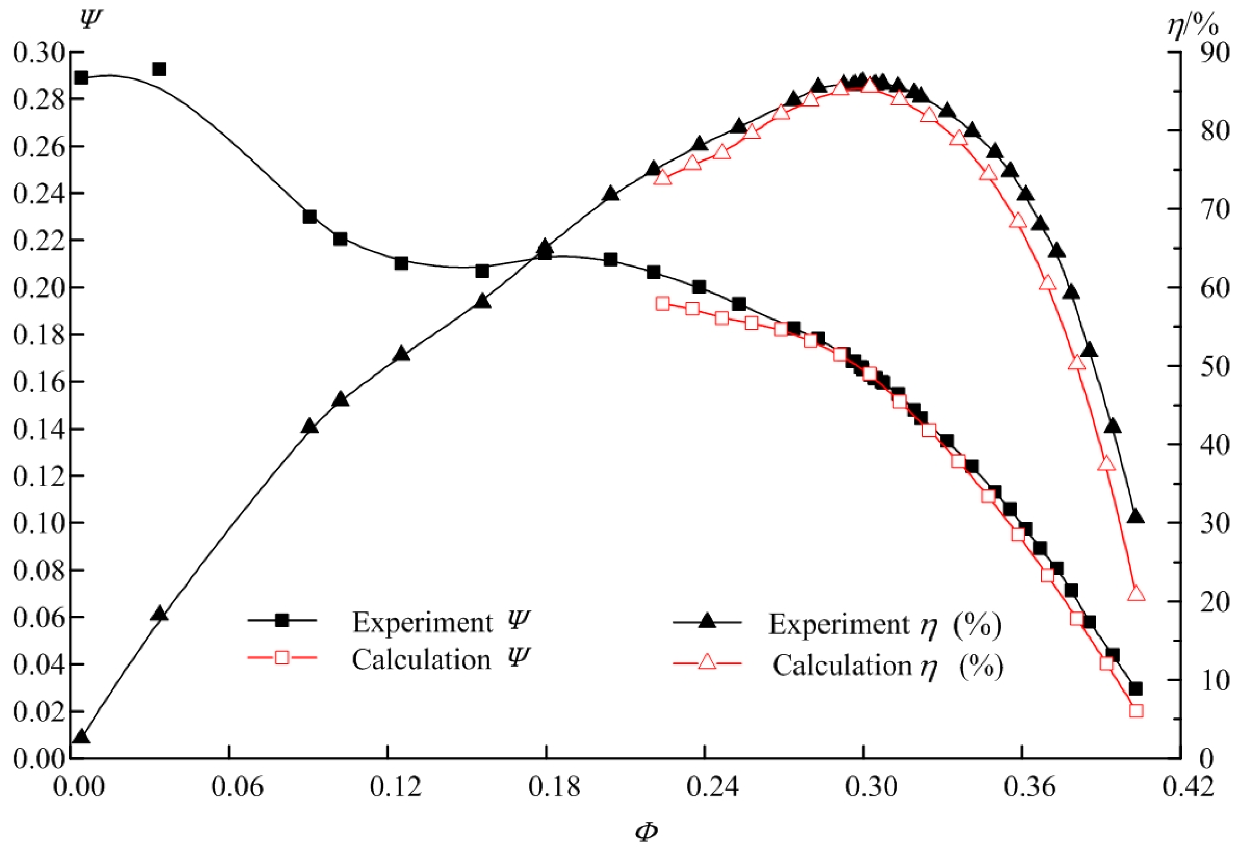
4.1. Energy Performance

Experimental measurement of the tested pump was conducted at Beifang Investigation, Design &Research Co., Ltd, Tianjin, China. The test loop mainly contained a water supply section, a pump section and an exhaust section. The main hydraulic performances of head and efficiency at different flow rates are tested in the test loop. After the experimental data were obtained, the numerical simulation was performed according to the experimental testing conditions. Figure 6 shows the pump performance comparison between experiment and calculation, and it can be conclude that the simulation results are accurate with experimental data both in the variation trend and the specific values at the tested points, especially around the design flow rate of 540 kg/s. This finding verifies the reliability of numerical simulation. The flow rate and head are normalized by specific flow rate Φ = Q / n D 2 3 and specific head Ψ = g H / u 2 2 , where u2 is the circumferential velocity of the impeller.
Then, the energy performances of pumps with different tip clearance types are investigated. Table 1 shows the pump head and efficiency with different tip clearance types, and the results illustrate that the pump head and efficiency both decrease as the tip clearance increases. For an unsymmetrical tip clearance of 1 mm × 4 + 2 mm × 1 at 5 blade end, the pump head and efficiency are between the pump with tip clearance of 1 mm × 5 and the pump with tip clearance of 2 mm × 5.

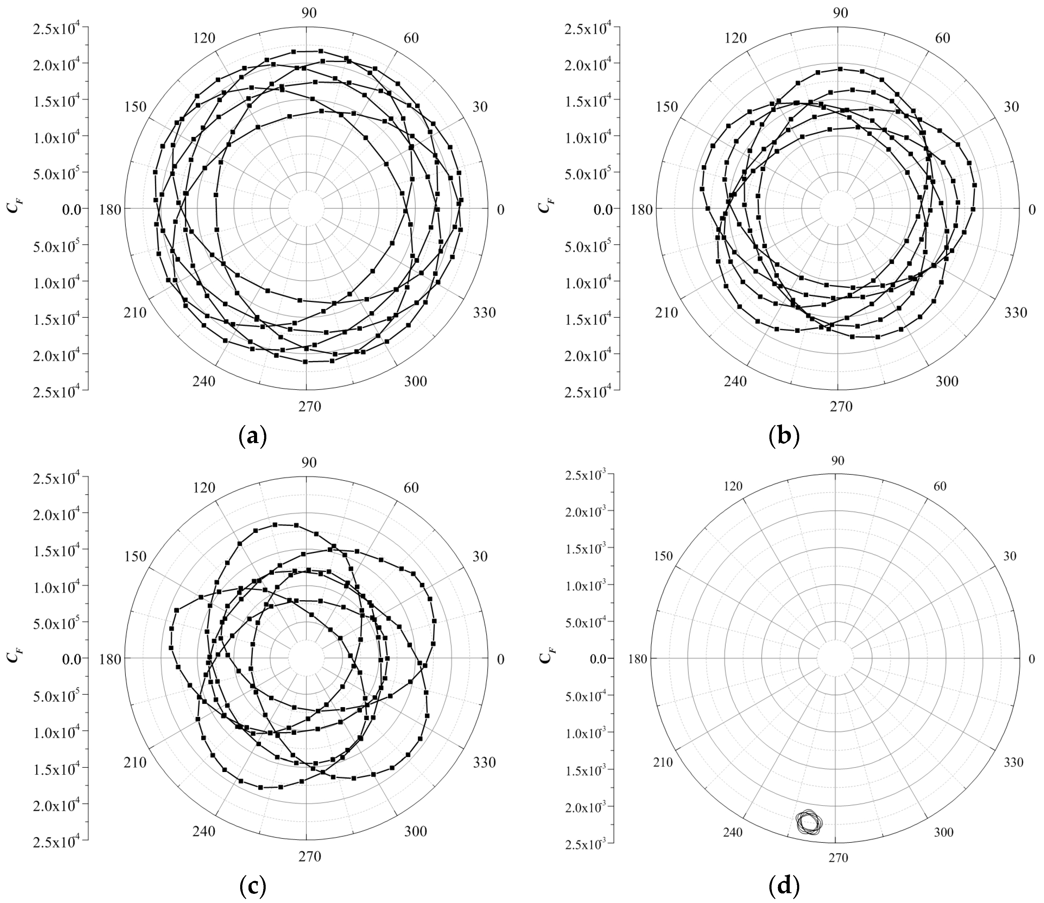
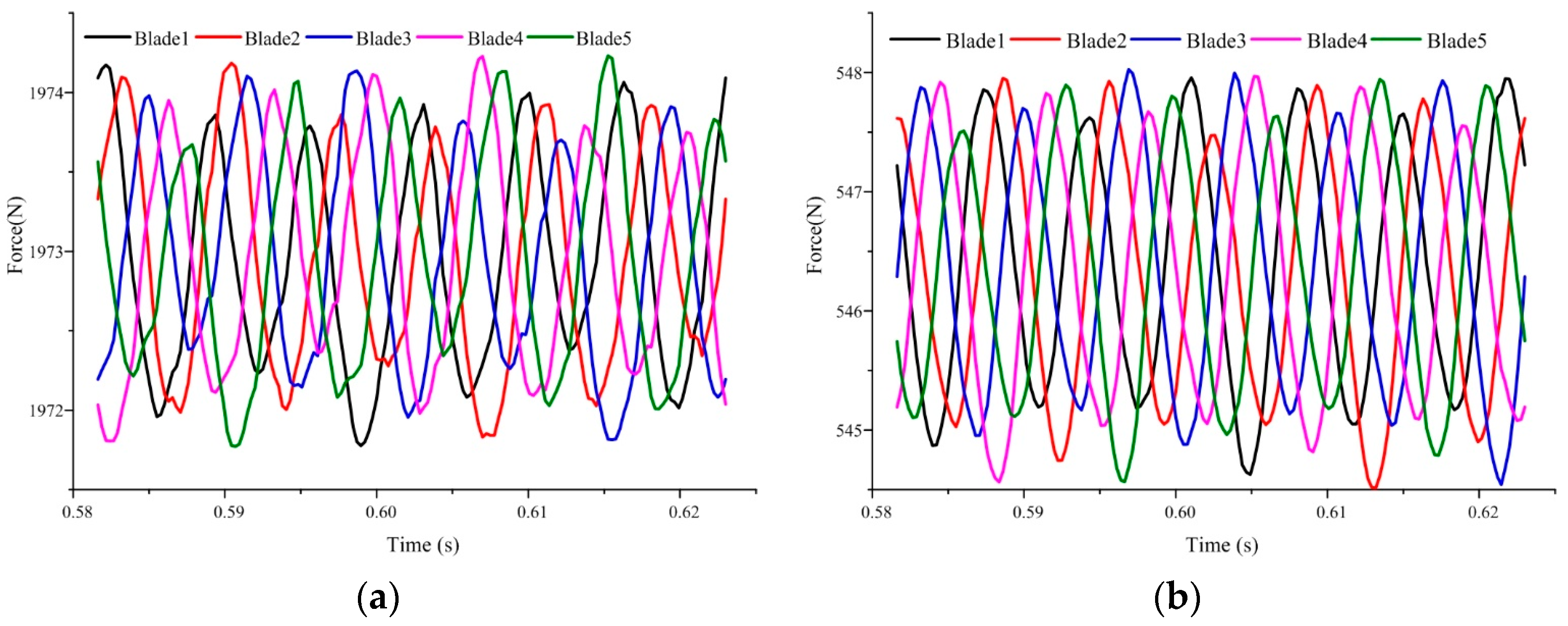
4.2. Radial Force on Principal Axis for Different Tip Clearances

Figure 7 shows the radial force vector on principal axis for 0mm tip clearance, 1 mm tip clearance, 2 mm tip clearance, and unsymmetrical tip clearance of 1 mm × 4 + 2 mm × 1, in a period of impeller revolution. The magnitude of the radial force on the principal axis is computed at each time step by means of a full integration of the pressure and shear stress on surfaces of hub and blades. Then, the polar coordinate system is used to show the radial force vector. The radial force F is normalized by the radial force coefficient, C F = F / ( 0.5 π D 2 b 2 ρ u 2 2 ) , where ρ is the fluid density and b2 is the blade width at the outlet.
Given that the time step is set to 1/160 period of impeller revolution in the transient calculation, 160 data points are in a period of impeller revolution as shown in Figure 7. Evidently, the radial force vector trace with 160 data points is a closed circle composed of 6 individual ellipses for four tip clearance types because in a period of impeller revolution, the phase difference of the radial force on blades periodically changes 6 times. Owing to the rotor stator interaction, the radial force vector on the principal axis completes a full trace with 6 individual ellipses. In symmetrical tip clearance, the trajectory center is located at (−0.000356, −0.002221), instead of the coordinate system center (0, 0).
Above all, the phenomenon of 6 individual ellipses for radial force in a period of impeller revolution is investigated. The radial force on the principal axis of a working pump mainly originates from the working fluid, especially the uneven flow field in the impeller. Thus, to study the relationship between flow characteristics and radial force on principal axis, the distribution of flow rate in 5 individual flow channels of the impeller is analyzed.
The volume center of each flow channel is calculated as follows:
x = C V x i d V C V d V ,   y = C V y i d V C V d V
where xi and yi are the coordinates of each mesh, and CV is the control volume of the individual flow channel between two adjacent blades. According to this formula, the x and y coordinates of the volume center for each flow channel can be calculated. The volume in 5 individual flow channels of the impeller is evenly distributed around the axis; therefore, the total vector of volume in the impeller is 0. However, the mass flow rates are uneven in 5 individual flow channels, therefore, the total vector of mass flow in an impeller does not equal 0 and varies with impeller rotation.
In general, the fluid water in the pump under normal working conditions is assumed to be incompressible, and therefore, in each flow channel the vector of mass flow is calculated by multiplying the vector of volume center and mass flow rate. Then, the total vector of the mass flow in an impeller is obtained. According to the preceding analysis, the mass flow rates in 5 individual flow channels are monitored by using a monitoring plane between two adjacent blades as shown in Figure 8.
Figure 9 shows the time revolution of vector angles for principal axis force and total mass flow rate. The results show that the two vector angles are nearly the same with 6 periods during a period of impeller revolution. Therefore, the conclusion can be made that the total radial force on principal axis is closely related to the fluctuation of mass flow rate in each single flow channel.
Figure 10 shows the fluctuation of the radial force on the blade pressure and suction sides in a period of impeller revolution. The results show that the radial force on the pressure sides of blade 1 to 5 is in a range of 1971 N to 1975 N, whereas radial force on the suction sides of blades 1–5 is in the range of 544 N and 548 N. The difference in radial force on the pressure and suction sides is derived from the uneven distribution of pressure in a flow channel and definitely influences the work ability of the impeller. In a period of impeller revolution, all the radial forces on the pressure and suction sides for blades 1 to 5 present 6 cycles, and correspond to the 6 individual ellipses of the radial force in a period of impeller revolution.

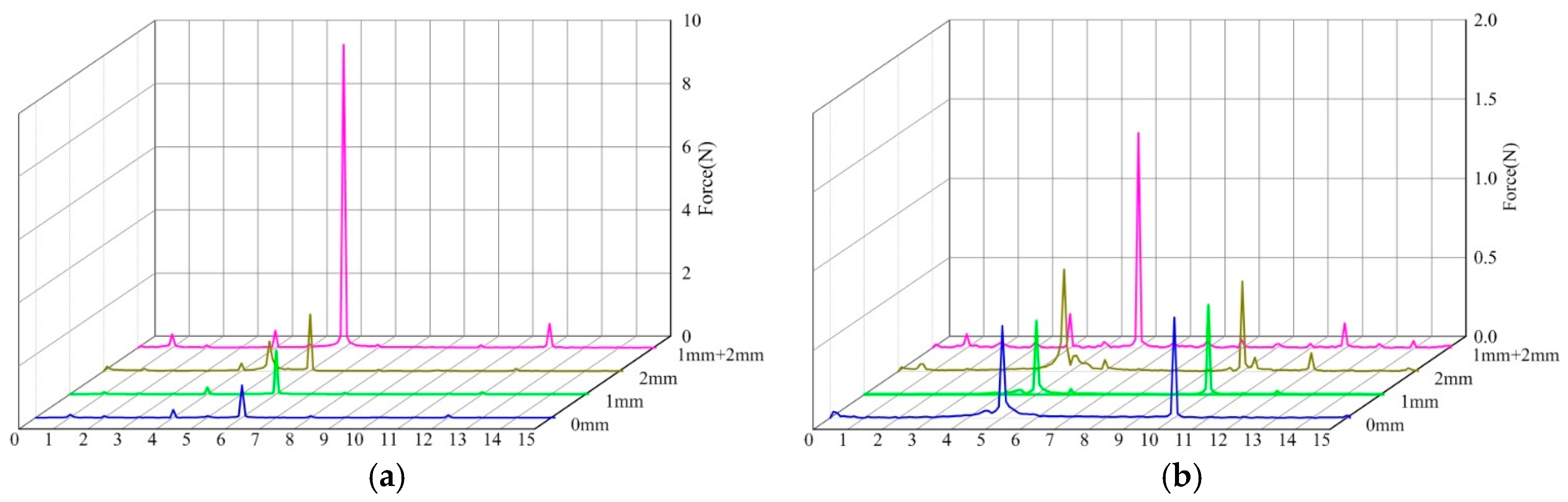
4.3. Spectral Analysis of Radial Force for Symmetrical and Unsymmetrical Tip Clearances

A Fast Fourier transform (FFT) is conducted to investigate the dominant frequency and corresponding amplitude of radial force fluctuations. Figure 11 shows the frequency spectra of the radial force on principal axis for different tip clearances. The impeller rotating frequency is fi = n/60 = 1450/60 = 24.17 Hz, and the blade passing frequency is fBPF = n × z/60 = 1450 × 5/60 = 120.83 Hz, which is five 5 times that of fi. In Figure 11, the horizontal coordinate is set as a multiple of fi.
The results show that the dominant frequencies of the radial force on the hub for 0 mm, 1 mm, 2 mm and 1 mm + 2 mm are all 6fi, and the maximum amplitudes on the dominant frequencies are 1.0 N, 1.4 N, 1.7 N, 9.6 N respectively. The dominant frequencies of the radial force on the suction side of blade for 0 mm, 1 mm, 2 mm and 1 mm + 2 mm are 10fi, 10fi, 5fi and 6fi respectively, and the maximum amplitudes on the dominant frequencies are 0.6 N, 0.6 N, 0.6 N and 1.4 N respectively.
It can be concluded that the dominant frequencies of the radial force on the hub and blade are 5fi, 6fi or 10fi, which correspond to the blade number, vane number or double blade number originating from the rotor stator interaction. On the hub and the blade, the maximum amplitudes for the unsymmetrical tip clearance of 1 mm + 2 mm exceed that for symmetrical tip clearances of 0 mm, 1 mm and 2 mm. Therefore, the unsymmetrical tip clearance strengthens the fluctuation of radial force and influence the operational stability of the mixed-flow pump.

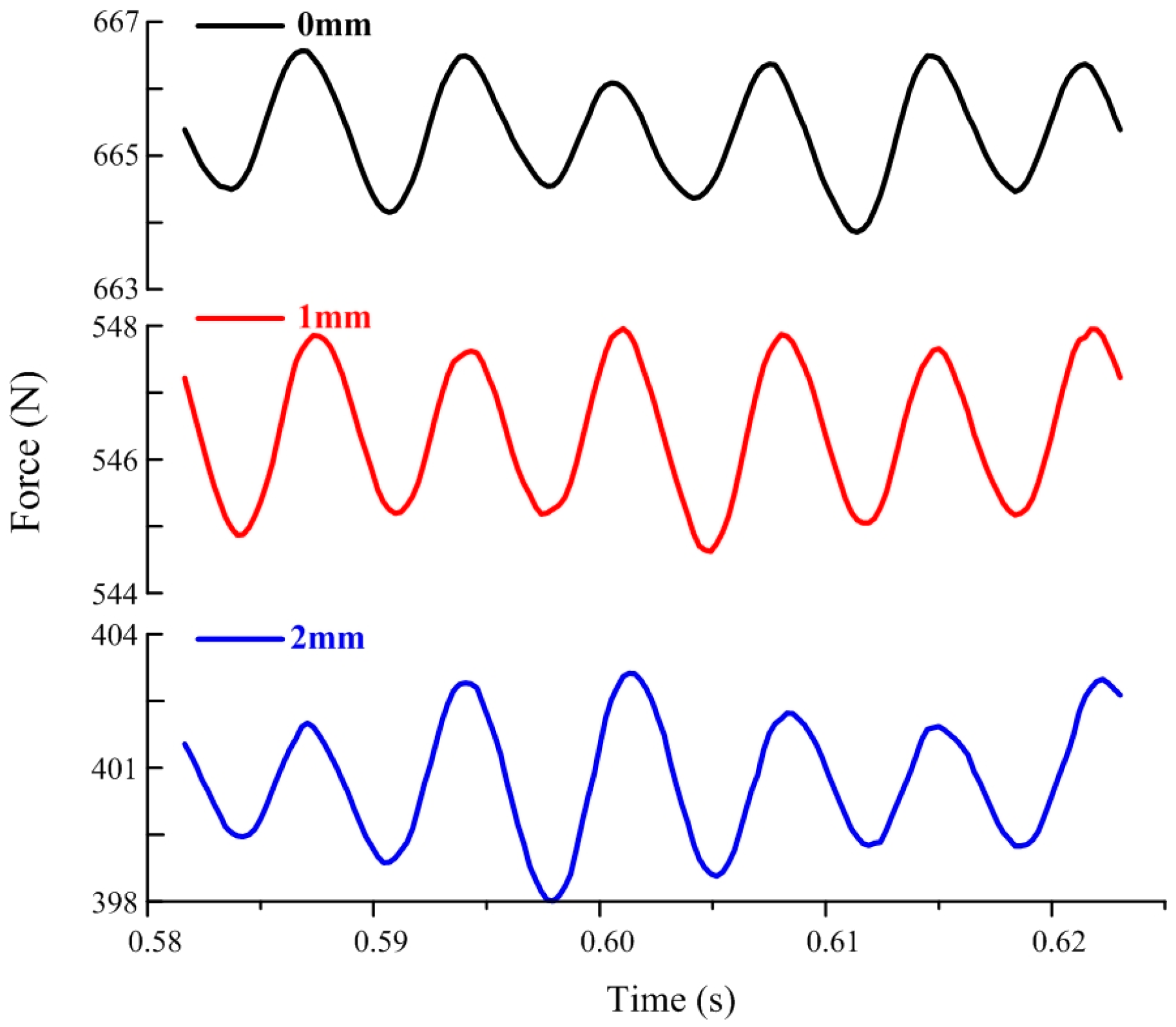
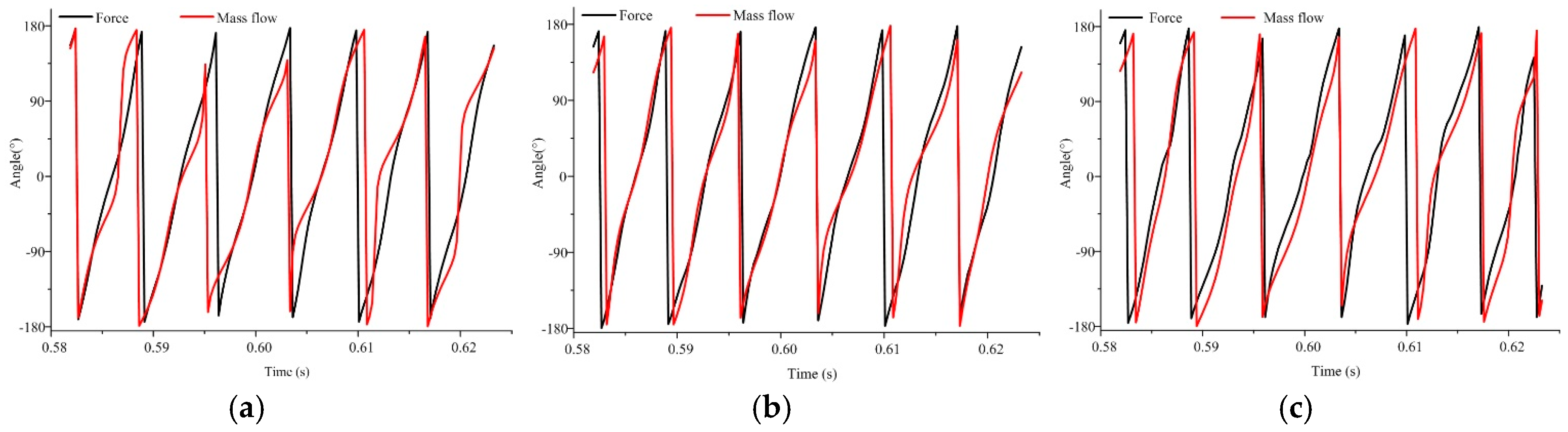
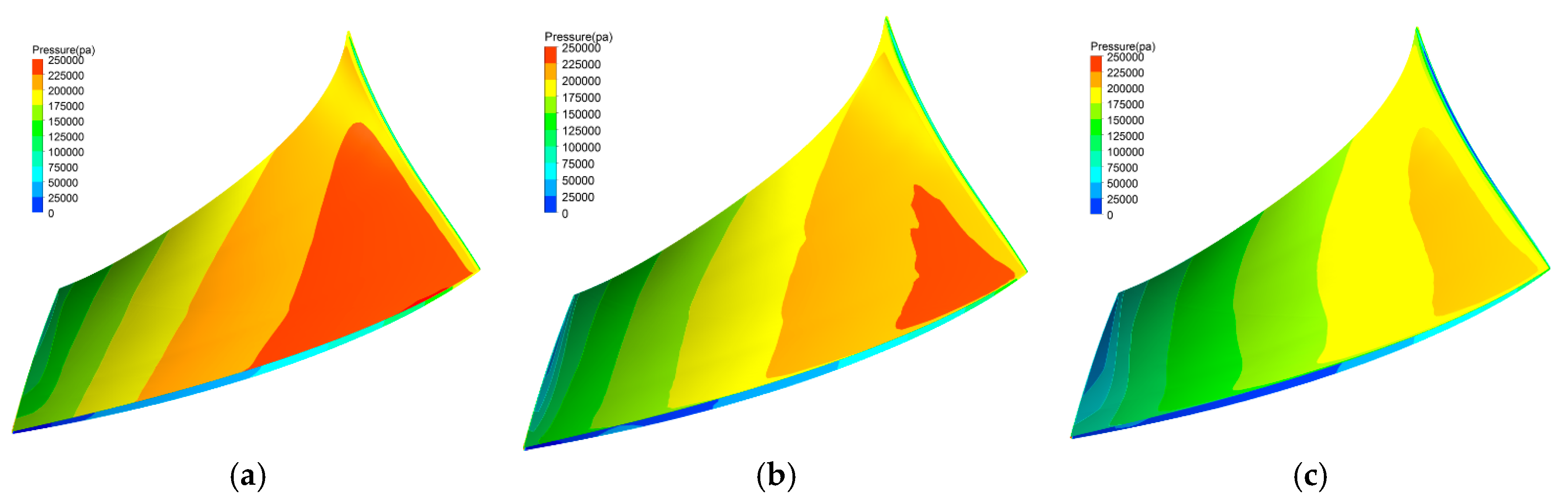
4.4. Analysis of Symmetrical Tip Clearance

Figure 12 shows the time revolution of the radial force on the blade suction side of pumps with 0 mm, 1 mm and 2 mm tip clearances. The fluctuation pattern of the radial force shows 6 cycles in a period of impeller revolution, which corresponds to the 6 guide vanes and flow rate variation in the impeller.
With the tip clearance increase from 0 mm and 1 mm to 2mm, the radial force on the blade suction side decreases. This phenomenon is related to leakage flow. Table 2 shows the leakage flow and radial force for different tip clearances. The plane between the blade tip and shroud is used to monitor the leakage flow rate. The last revolution with 160 time steps in the transient calculation is selected to record 160 values of radial force and leakage flow rate, and then the time-average radial force and leakage flow rate are calculated by 160 values. As the tip clearance increases from 0 mm, 1 mm to 2 mm, the leakage flow increases from 0 kg/s, 2.04 kg/s to 4.42 kg/s, and then the radial force decreases from 2174.96 N to 1687.52 N on the blade pressure side, from 665.34 N to 400.31 N on blade suction side.
Figure 13 shows the pressure distribution on the blade pressure side of the pumps with tip clearance of 0 mm, 1 mm and 2 mm. The results show that the pressure gradually increases from blade inlet to outlet for three cases because of the input power from the principal axis. With increasing tip clearance from 0 mm to 2 mm, the maximum pressure and high pressure region on the blade pressure side decrease, and the pressure gradient becomes more gradual. The pressure on the blade side is closely related to the radial force; therefore, the radial force decreases accordingly as the tip clearance increases, as shown in Table 2.
As shown in Table 3, the pump head also decreases with the increasing of tip clearance. The relationship between the head and radial force is nearly linear, which means that the head decreases with decreasing radial force on the blade. The reason is that the lower radial force represents weaker work capability and then results in lower head.

4.5. Analysis of Unsymmetrical Tip Clearance

As presented in Figure 7, a considerable difference in the radial force vector on the principal axis is observed for symmetrical and unsymmetrical tip clearances. This phenomenon is related to the uneven leakage flow rate for unsymmetrical tip clearances. Table 4 shows the leakage flow rate and radial force for different blades, and the naming scheme of each blade is shown in Figure 2. The results show that for blades A1 to A4 with 1 mm tip clearance, the leakage flow rates are nearly the same at about 2.00 kg/s, and the radial forces on the pressure and suction sides are also equally about 1940 N and 510 N. However, the leakage flow rate crossing the blade B increases to 4.59 kg/s because of the larger tip clearance size. As the leakage flow rate increases, the mass flow at the pressure side of blade B decreases and then the radial force on the pressure side decreases to 1873 N; meanwhile, the mass at the suction side of blade B increases, and then the radial force on the pressure side increases to 560 N.
Figure 14 shows the streamline near blade end for unsymmetrical tip clearance in an impeller. The difference of the tip clearance size can be clearly observed in the shaft section, and the streamlines around different tip clearances are also different. For blades A1 to A4 with a tip clearance of 1 mm, the regions influenced by the leakage vortex near the blade end are virtually the same. As the tip clearance of blade B increases to 2 mm, the influenced region by leakage vortex expands both at the blade pressure and suction sides. The larger the vortex region appears, the more complicated the flow pattern is. Therefore, the radial force on blade B is different from those of the other 4 blades because of the unsymmetrical tip clearance.

5. Conclusions

The energy performance and radial force characteristics of a mixed flow pump with symmetrical and unsymmetrical tip clearances are investigated by selecting four types of tip clearance as follows: 0 mm × 5, 1 mm × 5, 2 mm × 5 and 1 mm × 4 + 2 mm × 1. According to the numerical simulation and theoretical analysis, the following conclusions can be drawn:
(1)
Tip clearance markedly influences pump head and efficiency. The energy performance of the pump decreases as the tip clearance increases. In the comparison of symmetrical tip clearance, the pump head and efficiency of the unsymmetrical tip clearance 1 mm × 4 + 2 mm × 1 is between that of the symmetrical tip clearance 1 mm × 5 and tip clearance 2 mm × 5.
(2)
In the comparison of the symmetrical tip clearance, the magnitude of the radial force on the principal axis of the unsymmetrical tip clearance considerably increases, to approximately 15 times that of the symmetrical tip clearance, and the center of it moves from the coordinate origin to the third quadrant.
(3)
Spectrum analysis shows that the dominant frequencies of the radial force on the hub and the blade are 5fi, 6fi, or 10fi. In the comparison of the symmetrical tip clearance, the maximum amplitudes on the dominant frequency of the unsymmetrical tip clearance substantially increase to approximately 7 times that of the symmetrical tip clearance.
(4)
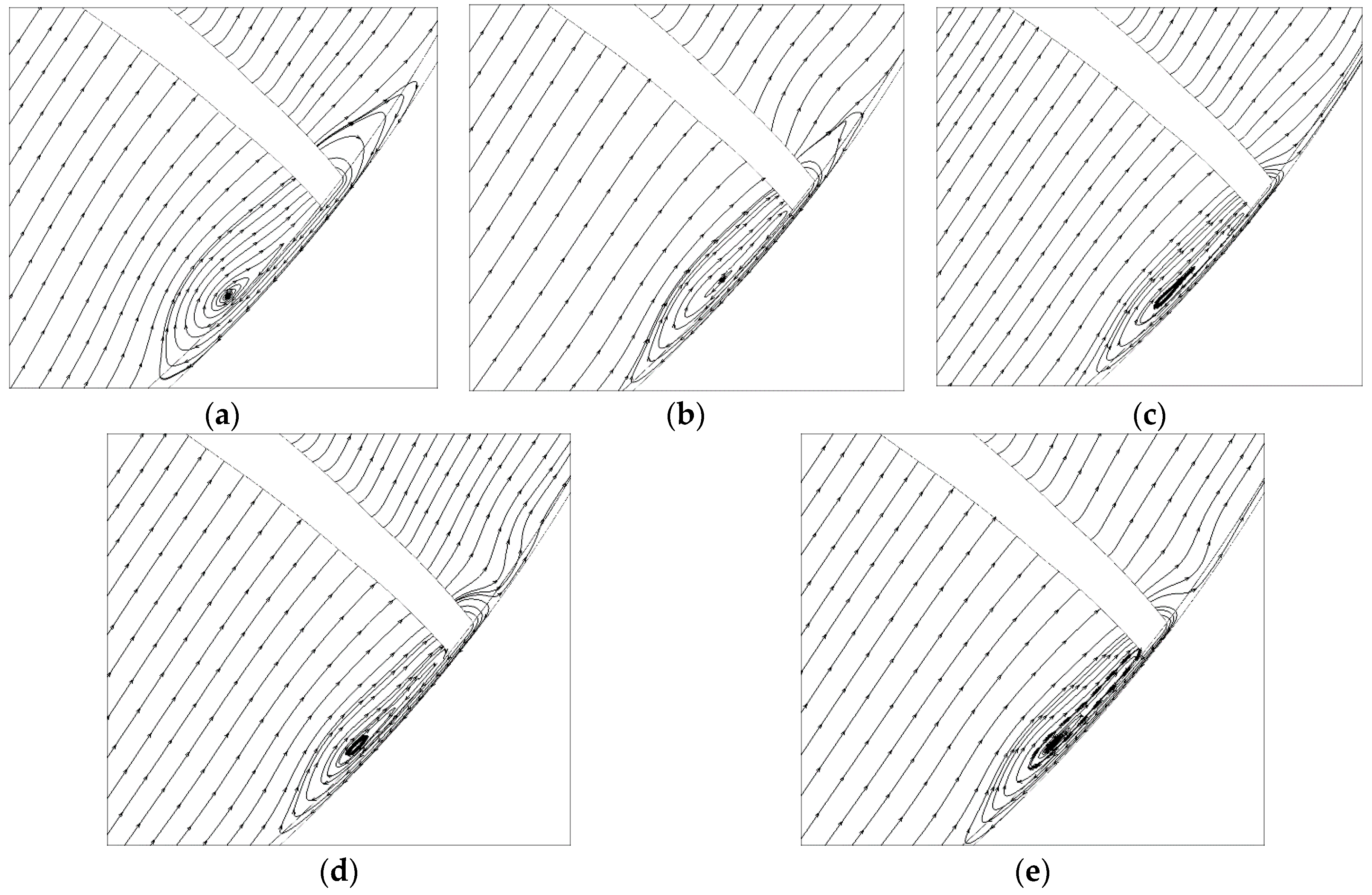
The leakage flow rates through blade tips vary in an impeller with unsymmetrical tip clearance, thereby making the flow pattern in each single channel uneven, generating a strong radial force on the principal axis, and thus affecting the operation stability of a mixed flow pump.

Acknowledgments

This work has been supported by the Tsinghua University Initiative Scientific Research Program (Grant number 2014z21041), the Beijing Natural Science Foundation (Grant number 3164045), and the National Natural Science Foundation of China (Grant numbers 51579006, 51679122).

Author Contributions

Yue Hao and Lei Tan conceived and designed the experiments and simulations; Yue Hao, Yabin Liu and Yun Xu performed the experiments and simulations; Lei Tan and Baoshan Zhu analyzed the data; Jinsong Zhang contributed analysis tools; Yue Hao and Lei Tan wrote the paper.

Conflicts of Interest

The authors declare no conflict of interest.

References

  1. Bing, H.; Tan, L.; Cao, S.L.; Lu, L. Prediction method of impeller performance and analysis of loss mechanism for mixed-flow pump. Sci. China Technol. Sci. 2012, 55, 1988–1998. [Google Scholar] [CrossRef]
  2. Tan, L.; Cao, S.L.; Wang, Y.M.; Zhu, B.S. Direct and inverse iterative design method for centrifugal pump impellers. Proc. Inst. Mech. Eng. Part A J. Power Energy 2012, 226, 764–775. [Google Scholar] [CrossRef]
  3. Tan, L.; Zhu, B.S.; Cao, S.L.; Wang, Y.M. Influence of blade wrap angle on centrifugal pump performance by numerical and experimental study. Chin. J. Mech. Eng. 2014, 27, 171–177. [Google Scholar] [CrossRef]
  4. Gearhart, W.S. Tip clearance cavitation in shrouded underwater propulsors. J. Aircr. 1966, 3, 185–192. [Google Scholar]
  5. Laborde, R.; Chantrel, P.; Mory, M. Tip clearance and tip vortex cavitation in an axial flow pump. J. Fluids Eng. 1997, 119, 680–685. [Google Scholar] [CrossRef]
  6. You, D.; Wang, M.; Moin, P.; Mittal, R. Study of tip-clearance flow in turbomachines using large-eddy simulation. Comput. Sci. Eng. 2004, 6, 38–46. [Google Scholar]
  7. Wu, H.X.; Miorini, R.L.; Katz, J. Measurements of the tip leakage vortex structures and turbulence in the meridional plane of an axial water-jet pump. Exp. Fluids 2011, 50, 989–1003. [Google Scholar] [CrossRef]
  8. Wu, H.X.; Tan, D.; Miorini, R.L.; Katz, J. Three-dimensional flow structures and associated turbulence in the tip region of a waterjet pump rotor blade. Exp. Fluids 2011, 51, 1721–1737. [Google Scholar] [CrossRef]
  9. Miorini, R.L.; Wu, H.X.; Katz, J. The internal structure of the tip leakage vortex within the rotor of an axial waterjet pump. J. Turbomach. 2012, 134. [Google Scholar] [CrossRef]
  10. Wu, H.X.; Miorini, R.L.; Tan, D.; Katz, J. Turbulence within the tip-leakage vortex of an axial waterjet pump. AIAA J. 2012, 50, 2574–2587. [Google Scholar] [CrossRef]
  11. Zhang, D.S.; Shi, W.D.; van Esch, B.P.M.; Shi, L.; Dubussion, M. Numerical and experimental investigation of tip leakage vortex trajectory and dynamics in an axial flow pump. Comput. Fluids 2015, 112, 61–71. [Google Scholar] [CrossRef]
  12. Zhang, D.S.; Shi, L.; Shi, W.D.; Zhao, R.J.; Wang, H.Y.; van Esch, B.P.M. Numerical analysis of unsteady tip leakage vortex cavitation cloud and unstable suction-side-perpendicular cavitating vortices in an axial flow pump. Int. J. Multiph. Flow 2015, 77, 244–259. [Google Scholar] [CrossRef]
  13. Zhang, D.S.; Shi, W.D.; Pan, D.Z.; Dubussion, M. Numerical and Experimental Investigation of Tip Leakage Vortex Cavitation Patterns and Mechanisms in an Axial Flow Pump. J. Fluids Eng. 2015, 137. [Google Scholar] [CrossRef]
  14. Tan, L.; Zhu, B.S.; Cao, S.L.; Wang, Y.C.; Wang, B.B. Numerical simulation of unsteady cavitation flow in a centrifugal pump at off-design conditions. Proc. Inst. Mech. Eng. Part C J. Mech. Eng. Sci. 2014, 228, 1994–2006. [Google Scholar]
  15. Tan, L.; Zhu, B.S.; Wang, Y.C.; Cao, S.L.; Gui, S.B. Numerical study on characteristics of unsteady flow in a centrifugal pump volute at partial load condition. Eng. Comput. 2015, 32, 1549–1566. [Google Scholar] [CrossRef]
  16. Wang, Y.C.; Tan, L.; Zhu, B.S.; Cao, S.L.; Wang, B.B. Numerical investigation of influence of inlet guide vanes on unsteady flow in a centrifugal pump. Proc. Inst. Mech. Eng. Part C J. Mech. Eng. Sci. 2015, 18, 3405–3416. [Google Scholar]
  17. Qu, W.S.; Tan, L.; Cao, S.L.; Wang, Y.C.; Xu, Y. Numerical investigation of clocking effect on a centrifugal pump with inlet guide vanes. Eng. Comput. 2016, 33, 465–481. [Google Scholar] [CrossRef]
  18. Guo, S.J.; Okamoto, H. An experimental study on the fluid forces induced by rotor-stator interaction in a centrifugal pump. Int. J. Rotating Mach. 2003, 9, 135–144. [Google Scholar] [CrossRef]
  19. Rodriguez, C.G.; Egusquiza, E.; Santos, I.F. Frequencies in the vibration induced by the rotor stator interaction in a centrifugal pump turbine. J. Fluids Eng. 2007, 129, 1428–1435. [Google Scholar] [CrossRef]
  20. Suzuki, T.; Prunieres, R.; Horiguchi, H.; Tsukiya, T.; Taenaka, Y.; Tsujimoto, Y. Measurements of rotordynamic forces on an artificial heart pump impeller. J. Fluids Eng. 2007, 129, 1422–1427. [Google Scholar] [CrossRef]
  21. Barrio, R.; Blanco, E.; Parrondo, J.; González, J.; Fernández, J. The effect of impeller cutback on the fluid-dynamic pulsations and load at the blade-passing frequency in a centrifugal pump. J. Fluids Eng. 2008, 130. [Google Scholar] [CrossRef]
  22. Barrio, R.; Fernándezb, J.; Blancoa, E.; Parrondoa, J. Estimation of radial load in centrifugal pumps using computational fluid dynamics. Eur. J. Mech. B/Fluids 2011, 30, 316–324. [Google Scholar] [CrossRef]
  23. Tan, L.; Cao, S.L.; Wang, Y.M.; Zhu, B.S. Numerical simulation of cavitation in a centrifugal pump at low flow rate. Chin. Phys. Lett. 2012, 29, 147021–147024. [Google Scholar] [CrossRef]
  24. Tan, L.; Zhu, B.S.; Cao, S.L.; Wang, Y.M. Cavitation flow simulation for a centrifugal pump at a low flow rate. Chin. Sci. Bull. 2013, 58, 949–952. [Google Scholar]
Figure 1. (a) Pump and (b) impeller in experimental measurement.
Energies 10 00057 g001
Figure 2. Schematic of tip clearance types: (a) 0 mm; (b) 1 mm; (c) 2 mm and (d) unsymmetrical tip.
Energies 10 00057 g002
Figure 3. Computational domain of the mixed-flow pump: (a) Computational domain and (b) Impeller mesh.
Energies 10 00057 g003
Figure 4. Mesh independence test.
Energies 10 00057 g004
Figure 5. Time step independence test: (a) Blade A3 Suction Side and (b) Time step independence test.
Energies 10 00057 g005
Figure 6. Comparison of pump performance between experiment and simulation.
Energies 10 00057 g006
Figure 7. Radial force vector on principal axis for different tip clearances: (a) 0 mm; (b) 1 mm; (c) 2 mm and (d) 1 mm + 2 mm.
Energies 10 00057 g007
Figure 8. Monitoring plane of mass flow rate.
Energies 10 00057 g008
Figure 9. Time revolution of vector angles for principal axis force and total mass flow rate: (a) 0 mm; (b) 1 mm and (c) 2 mm.
Energies 10 00057 g009
Figure 10. Time revolution of radial force on blade pressure and suction sides for 1 mm tip clearance: (a) Blade pressure side and (b) Blade suction side.
Energies 10 00057 g010
Figure 11. Frequency domain of radial force on hub and blade suction side: (a) Radial force spectral on hub and (b) Radial force spectral on blade suction side.
Energies 10 00057 g011
Figure 12. Time revolution of radial force on the blade suction side for different tip clearances.
Energies 10 00057 g012
Figure 13. Pressure distribution on blade pressure side for different tip clearances: (a) 0 mm; (b) 1 mm and (c) 2 mm.
Energies 10 00057 g013
Figure 14. Streamline near blade end for unsymmetrical tip clearance: (a) Blade B; (b) Blade A1; (c) Blade A2; (d) Blade A3 and (e) Blade A4.
Energies 10 00057 g014
Table 1. Energy performances of pumps with different tip clearances.
ParameterSymbolUnitValue
Rated Flow RateQdm3/s0.54
Rated HeadHm17
Rotational Speednrpm1450
Number of Guide VaneZg 6
Number of Impeller BladeZi 5
Diameter of Impeller InletD1mm278
Diameter of Impeller OutletD2mm420
Table 2. Leakage flow and radial force for different tip clearances.
Tip Clearance (mm)Average Leakage Flow Rate (kg/s)Average Pressure Side Radial Force (N)Average Suction Side Radial Force (N)
002174.96665.34
12.041972.96546.41
24.421687.52400.31
Table 3. Energy performances of pumps with different tip clearances.
Tip Clearance TypeHead (m)Efficiency
0 mm × 516.920.8552
1 mm × 515.260.8148
2 mm × 512.820.7536
1 mm × 4 + 2 mm × 114.790.8027
Table 4. Leakage flow rate for 5 unsymmetrical tip clearances in an impeller.
Tip NameTip Clearance (mm)Time Average Leakage Flow Rate (kg/s)Time Average Radial Force on Pressure Side (N)Time Average Radial Force on Suction Side (N)
Blade-B24.591873560
Blade-A112.111926518
Blade-A212.031948511
Blade-A312.051942518
Blade-A412.051932500

