Article

Coordinated Control of Superconducting Fault Current Limiter and Superconducting Magnetic Energy Storage for Transient Performance Enhancement of Grid-Connected Photovoltaic Generation System

1
School of Electrical Engineering, Wuhan University, Wuhan 430072, China
2
Hubei Energy Group Co., Ltd., Wuhan 430077, China
3
State Grid Shandong Electric Power Research Institute, Jinan 250000, China
4
State Key Laboratory of Advanced Electromagnetic Engineering and Technology, Huazhong University of Science and Technology, Wuhan 430074, China
*
Author to whom correspondence should be addressed.
Energies 2017, 10(1), 56; https://doi.org/10.3390/en10010056
Submission received: 23 September 2016 / Revised: 13 December 2016 / Accepted: 26 December 2016 / Published: 5 January 2017
(This article belongs to the Special Issue Grid-Connected Photovoltaic Systems)

Abstract

:
In regard to the rapid development of renewable energy sources, more and more photovoltaic (PV) generation systems have been connected to main power networks, and it is critical to enhance their transient performance under short-circuit faults conditions. This paper proposes and studies the coordinated control of a flux-coupling-type superconducting fault current limiter (SFCL) and a superconducting magnetic energy storage (SMES), to improve the fault ride through (FRT) capability and smooth the power fluctuation of a grid-connected PV generation system. Theoretical analyses of the device structure, operating principle and control strategy are conducted, and a detailed simulation model of 100 kW class PV generation system is built in MATLAB/SIMULINK. During the simulations of the symmetrical and asymmetrical faults, the maximum power point tracking (MPPT) control is disabled, and four different cases including without auxiliary, with SFCL, with SMES, and with SFCL-SMES, are compared. From the demonstrated results, the combination of without MPPT and with SFCL-SMES can more efficiently improve the point of common coupling (PCC) voltage sag, inhibit the DC-link overvoltage and alleviate the power fluctuation. Finally, a preliminary parameter optimization method is suggested for the SFCL and the SMES, and it is helpful to promote their future application in the real PV projects.

1. Introduction

Owing to the continuous increase in energy demands, black-outs, and environmental concerns regarding global warming, renewable energy sources have attracted more and more attention throughout the whole world to replace traditional fossil energy sources and achieve sustainable socio-economic development [1,2,3,4]. As a representative renewable energy source, photovoltaic (PV) generation technology will undoubtedly play an important role in the electricity conversion, and lots of grid-connected PV generation systems are expected to sell their generated power with advantageous price ratings fixed by governmental policies [5]. Moreover, considering the rapid development of computer and digital communication technologies [6,7,8,9,10,11,12,13,14,15,16,17,18], PV generation systems may be regarded as crucial components in the future energy internet.
From a number of practical engineering projects, PV generation systems are commonly connected to low-voltage and medium-voltage power distribution networks, and those established grid standards may focus on the issue of power quality, such as frequency and voltage stability [19]. In respect to the large-scale grid-connected PV systems, they are required to stay connected and contribute to the main power network in case of some severe voltage disturbances. A rough disconnection may cause many adverse conditions, and then negatively affect the security and stability of the network during and after faults [20,21,22]. It is also expected that the mentioned fault ride through (FRT) function will be extended for the large-scale low-voltage PV applications [23].
Currently, lots of scholars have put their attention to improving the low voltage ride through (LVRT) capability of a grid-connected PV generation system, and some useful solutions have been proposed [24,25,26,27,28,29,30,31,32,33,34,35,36,37]. Among them, software and hardware methods can be classified. Regarding software methods, an advanced or improved control strategy is commonly used. In respect to hardware method, an additional physical device will be generally adopted. If more specific classifications are performed in accordance with the difference in device materials, traditional and superconducting devices can be obtained. A brief introduction and analysis of them are stated as follows.
The advanced control strategies can be regarded as the software solutions. In [24], a coordinated control approach is to support the FRT function. This control approach is based on the large-scale two-stage power interface and can help to maintain the DC-link voltage, but the control performance may be seriously affected by the severity of a fault. In [25], a novel control strategy is suggested to achieve the FRT operation by use of the overload capability of grid-tied inverters. From the demonstrative results, this method’s performance will closely depend on the grid-tied inverters’ capacities. In [26], a flexible control of active power and reactive power is proposed for the stabilization of a grid-connected PV generation system. Although some contributions are obtained, the DC-link overvoltage is simply neglected. In [27,28], the control of single- and two-stage grid-connected voltage source inverters (VSIs) in PV power plants is developed to address the issue of inverter disconnecting under various grid faults. In [29], an adaptive DC-link voltage control method is proposed for achieving the FRT operation. The results show this control method can attenuate the double-line-frequency dc-link voltage ripple, and the dc-link voltage can be maintained within a safe operational range. Note that, although these advanced control strategies are effective to a certain extent, some severe short-circuit faults may be out of their control ranges, which will be mainly determined by the power inverters’ voltage grades and rated capacities.
Concerning the hardware solutions based on traditional devices, this paper mainly reviews chopper circuit, voltage restorer and fault current limiter (FCL). The chopper circuit with a resistor across the DC-link bus may be treated as the commonly used one [30,31]. Thus, the overvoltage induced in the DC-link capacitor is suppressed, and the overcurrents occurring on the AC-side of the grid inverter are limited, to realize the FRT operation. The main disadvantages of this approach are a lack of flexibility and controllability, and meanwhile, it does not fully consider the reactive current support. In [32], a dynamic voltage restorer (DVR) is used to enhance the PV generation system’s robustness against severe symmetrical/asymmetrical grid faults and voltage dips. For the DVR, it should consider the series transformer, converter, control system, and possible energy storage unit at the DC side. There may be a compromise on the capacity, cost and size of the DVR, and the ability of the DVR in limiting fault current can be improved further. In [33,34], a parallel-resonance bridge type FCL and a nonlinear control-based variable resistive type FCL are applied, respectively, and their contributions in a wind farm/PV/synchronous generator hybrid power system are assessed. From the results, both of the two FCLs may dissipate the surplus power and compensate the voltage sag, but they cannot play a more positive role in smoothing the power fluctuation. For the hardware solutions based on superconducting devices, the existing references are mainly related to the application of a superconducting magnetic energy storage (SMES) unit for the PV generation unit [35,36,37]. The SMES unit can adjust active power and reactive power to improve the power quality and assist the FRT operation. Nevertheless, the SMES unit’s performance in limiting the overcurrent is not appreciated.
Actually, two major applications of superconducting devices are superconducting fault current limiters (SFCLs) and SMES. They have many prominent advantages, such as lower loss, compacted size, fast response, high power density, and long life. SFCL is a very competitive countermeasure to protect an electrical power system from the damage due to short-circuit faults [38,39,40,41,42]. In the literature, different types of SFCLs have been suggested, and their performance in limiting the overcurrent and improving the voltage sag can be confirmed, but for the application of a SFCL in renewable energy sources, lots of works focus on wind turbines rather than PV generation units [43,44,45]. To ensure the power quality and operation stability of renewable energy, SMES can be appropriately applied because of its high power density, fast charging speed and flexible control strategy [46,47,48]. In addition, for an integrated utilization of the technical advantages of the two superconducting devices, some studies related to the coordinated control of SFCL and SMES have been performed, and the effects on improving the transient stability of a traditional power grid and enhancing the FRT capability of a wind farm have been verified in [49,50,51,52,53]. It is believed that, with the continuous development of economical high-temperature superconductors in the future, the combined use of SFCL and SMES can offer more competitiveness to be applied in the practical power industry. It should be specifically pointed out that few works study the application of SFCL and SMES in improving the FRT capability and smoothing the power fluctuation of a PV generation system.
According to the above-mentioned background, this paper proposes the coordinated control of a flux-coupling-type SFCL and a SMES unit to improve a grid-connected PV generation system’s transient performance under fault conditions. The article is organized in the following manner. Section 2, Section 3 and Section 4 present the theoretical model of a typical grid-connected PV system, state the structural principles of the flux-coupling-type SFCL and the SMES, and put forward the coordinated control scheme to enhance the FRT operation and smooth the power fluctuation. In Section 5, the detailed system modeling is carried out by use of the MATLAB software (R2012b, MathWorks, Natick, MA, USA), and digital simulation analyses are performed to assess the coordinated control’s effectiveness. Section 6 is devoted to suggesting a preliminary parameter optimization method for the SFCL and the SMES. In Section 7, conclusions are summarized and follow-up works are explored.

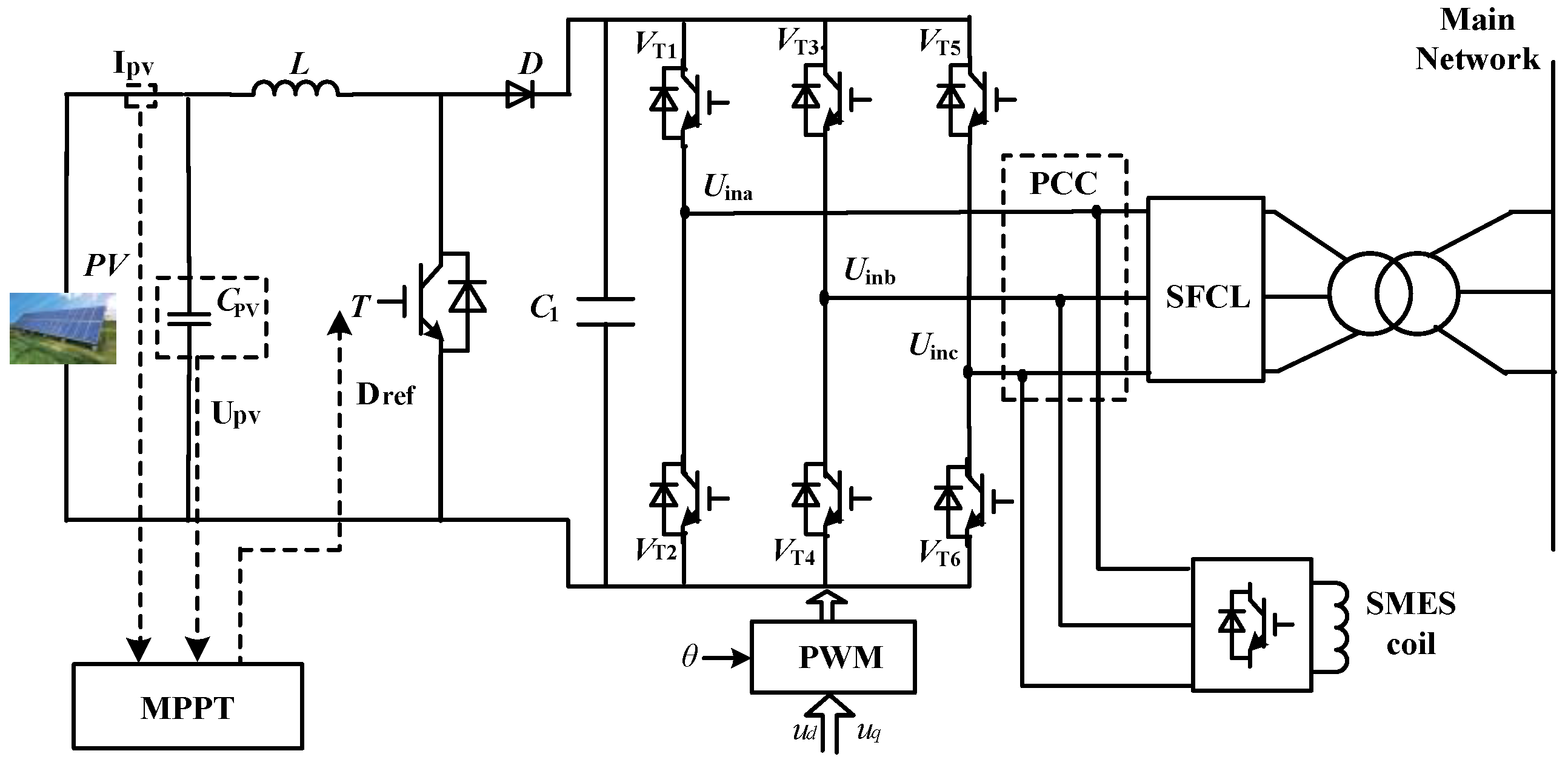
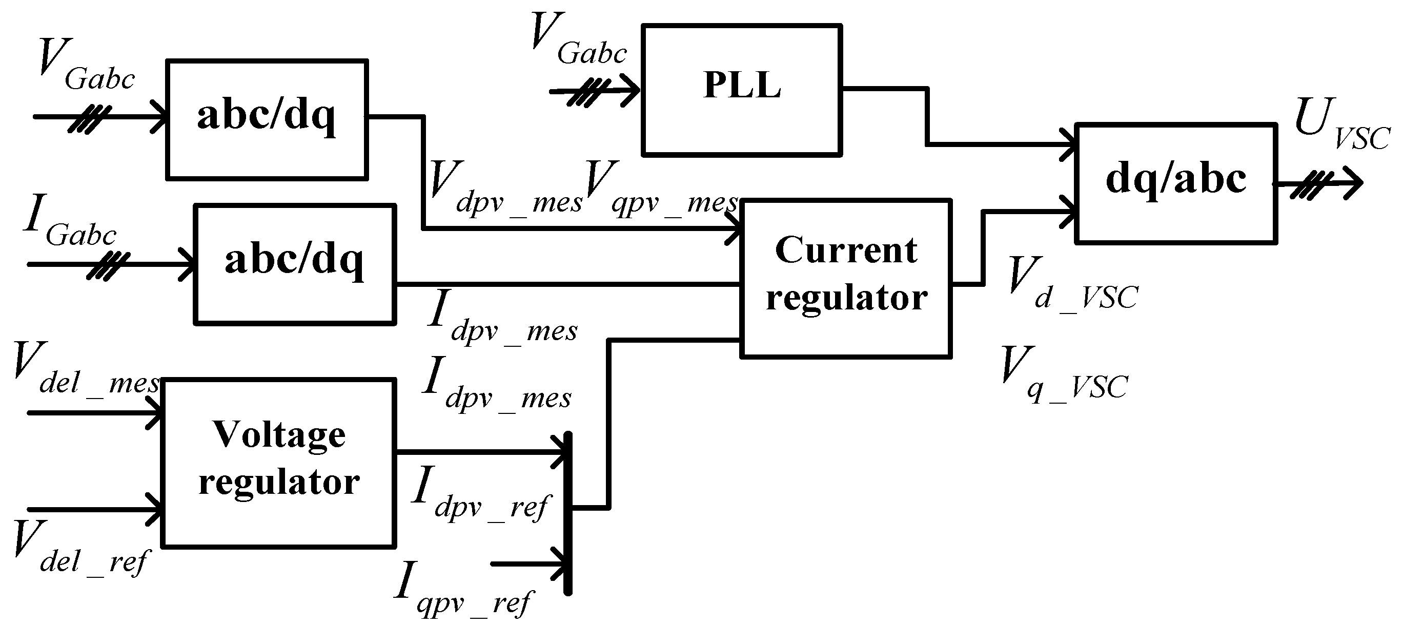
2. Theoretical Presentation of a Grid-Connected Photovoltaic Generation System

Figure 1 indicates the schematic configuration of a grid-connected PV generation system, which will be coupled to the main power network through a step-up transformer. The SFCL and the SMES unit are supposed to be installed at the point of common coupling (PCC) between the PV system and the set-up transformer for the main network.
Regarding the fault transient characteristics of the PV system, a brief analysis without SFCL and SMES is firstly presented in this section, and in the following sections, the two superconducting devices’ effects are analyzed in detail. Under normal condition, the maximum power point tracking (MPPT) control is used for the boost converter to ensure the PV system’s operating efficiency. The transistors VT1…VT6 denote the insulated gate bipolar transistors (IGBTs). The overall generated power from the PV system can be defined by:
P P V = P D C 1 + P g
where PDC1 is the power flowing through the DC-link capacitor C1; Pg is the power inserted by the inverter to the PCC; PPV is the PV array output. Supposing that the power electronic converter loss can be ignored under normal condition, PPV is approximately equal to Pg, and further it is obtained that PPV = Pg = 3VgIg, where Vg and Ig are recorded as the nominal root-mean-square (RMS) value of phase voltage and phase current, respectively.
When the short-circuit fault happens, the voltage over the PV generation unit will be dramatically affected, and the sudden voltage drop will reduce the grid-side power from Pg to Pgf. Note that, the current flowing in the fault resistance will include two components. One is from the PV generation unit, and the other is from the main network. If the fault resistance is relatively large and the high current is injected, the power maybe not reduced. If the fault resistance is relatively small (the most serious situation is Rg = 0), the power will enforcedly be reduced even though the high current is injected. In general, the power will decrease during faults. Meanwhile, the DC/DC converter proceeds to transmit the PV array’s maximum output power into the DC-link. In a mathematical method, the following equation can be obtained:
( P P V P g f ) Δ t = P D C 1 Δ t = 1 2 C D C 1 ( V D C 1 f 2 V D C 1 2 )
where VDC1 and VDC1-f denote the DC-link capacitance voltage before and after the fault, and ∆t is expressed as the duration of the fault. Because of Pgf = 3VgfIgf, the DC-link capacitor voltage under the fault is expressed as:
V D C 1 f = 2 ( P P V 3 V g f I g f ) Δ t C D C 1 + V D C 1 2
Owing to the drop of the PCC voltage, the power imbalance between PPV and Pgf will be inevitably caused, and the DC link voltage will be enforced to increase sharply.
In response to the PCC voltage sag, the inverter can adjust the reactive current for the voltage support. Thus, this section also suggests the control method of the inverter for the PV generation system. Regarding the VSI which plays a role in achieving the DC-AC power conversion for grid interface, it may use an external voltage regulator to generate the reactive current reference Iqpv-ref, and the reactive current’s mathematical characteristic can be expressed as [34]:
I q I n = { 0 ( 0.9 pu V P V 1.1 pu ) a a V P V ( 0.5 pu V P V 0.9 pu ) 1 ( V P V < 0.5 pu )
where the constant a is set as 2 and VPV is the PV voltage; Iq is the reactive current and In is the rated inverter current. In light of the required code, the VSI should provide full reactive current once the PV voltage is less than 50% of the nominal rating. The reference reactive current under the fault can be determined by Iqpv-ref = In × Iq/In, and then:
I q p v r e f = I n × I q I n = { 0 ( 0.9 pu V P V 1.1 pu ) I n ( a a V P V ) ( 0.5 pu V P V 0.9 pu ) I n ( V P V < 0.5 pu )
Further, the active current reference Idpv-ref can be expressed as [54]:
I d p v r e f = { I n ( 0.9 pu V P V 1.1 pu ) I n 2 I q p v r e f 2 ( 0.5 pu V P V 0.9 pu ) 0 ( V P V < 0.5 pu )
From the above-mentioned description and analysis, the control block diagram of the PV generation system’s VSI can be shown in Figure 2.

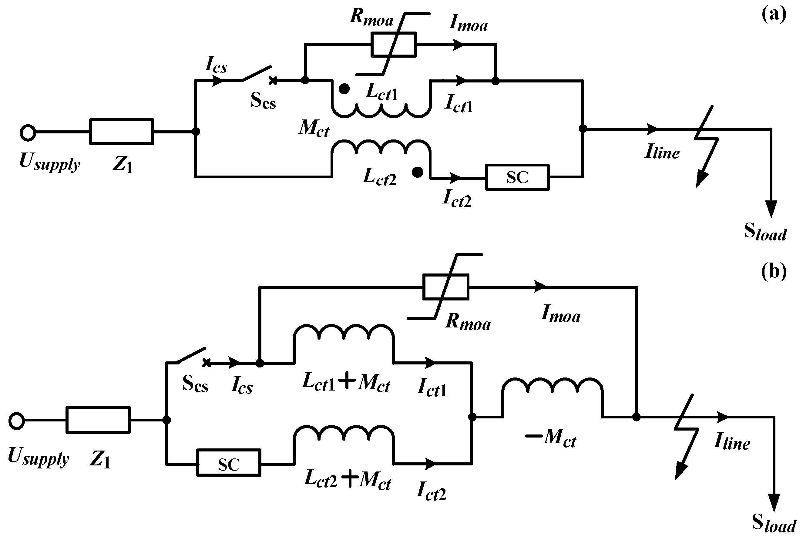
3. Configuration of the Superconducting Fault Current Limiter and Its Effects on the Photovoltaic Generation System

Figure 3a shows the schematic configuration of the flux-coupling-type SFCL [55,56,57]. This SFCL is mainly composed of a coupling transformer (CT), a controlled switch (CS) Scs, a superconducting coil (SC) and a metal oxide arrester (MOA). According to the CT’s equivalent circuit, Figure 3b shows the SFCL’s electrical equivalent structure. From this figure, the series and parallel connections among the coupling windings, SC, MOA and Scs become more intuitive.
In normal (no fault) condition, the CS is in the closed state and the SC is maintained in the zero-resistance state. Therefore, the CT’s operating impedance Zct will play a critical role on the SFCL’s performance characteristic, and Zct can be expressed as:
Z c t = j ω [ ( L c t 1 + M c t ) ( L c t 2 + M c t ) L c t 1 + L c t 2 + 2 M c t M c t ] = j ω ( L c t 1 L c t 2 M c t 2 ) / ( L c t 1 + L c t 2 + 2 M c t )
Supposing that k is the coupling coefficient with the expression of k = M c t / L c t 1 L c t 2 and n is the transformation ratio with the expression of n = L c t 1 / L c t 2 . Thus, the CT’s operating impedance can be rewritten as Zct = jωLct2(1 − k2)n2/(n2 + 2kn + 1). For k ≈ 1, Zct ≈ 0, and the non-inductive coupling is obtained. As the MOA is connected in parallel with the CT, it can be identified that the MOA is “short-circuited”. On this occasion, introducing the SFCL will have no influence on the main circuit and the PV generation system.
In the case of that the short-circuit fault happens, Scs will be opened rapidly, and meanwhile the MOA is able to suppress the switching overvoltage. The expected functions of the CS are to change the original electromagnetic property and invalidate the non-inductive coupling, and also the fault current in the SC will make the superconductor be quenching (The SC resistance is denoted as RSC). The current-limiting impedance ZSFCL can be denoted as:
Z S F C L = [ I . c t 2 ( R S C + j ω L c t 2 ) I . c t 1 j ω M c t ] / I . c t 2       = R S C + j ω L c t 2 I . c t 1 j ω M c t / I . c t 2
where Ict1 and Ict2 are the currents flowing through the CT’s primary and secondary coils, respectively, and the relationship between Ict1 and Ict2 can be derived as:
I . c t 1 I . c t 2 = j ω M c t R m o a + j ω L c t 1
From the Equations (8) and (9), ZSFCL is rewritten as ZSFCL = [RSC + jωLct2 + (knωLct2)2/(Rmoa + n2ωLct2). In view of Rmoa >> n2ωLct2, ZSFCLRSC + jωLct2 can be approximately obtained. According to the expression of the current-limiting impedance, the suggested SFCL is a resistive-inductive type (hybrid type) SFCL, and the combined use of the resistive and inductive components may bring more positive contributions, such as inhibiting active and reactive power fluctuations, providing critical assistance to reliabilities and securities of power systems more effectively [58,59]. In addition, considering the response speed of the CS will directly affect the rapidity of the current-limiting action, the conceptual design of a high-speed electromagnetic switch for the SFCL has been conducted, and this high-speed switch’s response time can be less than 0.5 ms [60].
For that the suggested SFCL is installed at the PCC, it will play its nature functions of suppressing the grid-side fault current and dissipating the surplus power, and considering the voltage compensation effects caused by the series current-limiting impedance, the PCC voltage during the fault can be enhanced to a relatively safe operation level. Therefore, the improvement of the PV generation’s FRT capability can be realized. With respect to the SFCL’s quantitative effects on the grid-side current, the following mathematical equations are obtained:
V g f d = R S C i d f + ( L f + L c t 2 ) ( d i d f d t ω f i q f ) + V P C C d
V g f q = R S C i q f + ( L f + L c t 2 ) ( d i q f d t + ω f i d f ) + V P C C q
where ωf is the angular frequency of the grid voltage; Lf is the filter inductance; subscripts d and q denote the d-axis and q-axis components; idf and iqf are the d-axis and q-axis components of the grid-side current. Based on the Equations (10) and (11), using the SFCL is able to suppress the AC currents flowing through the grid side. It should be noted that, introducing the SFCL can help to lower the demand of the reactive current provided by the VSI, and the SFCL’s specific performance will be constrained by the inductance parameters of the CT as well as the SC’s quench resistance and transient characteristic.

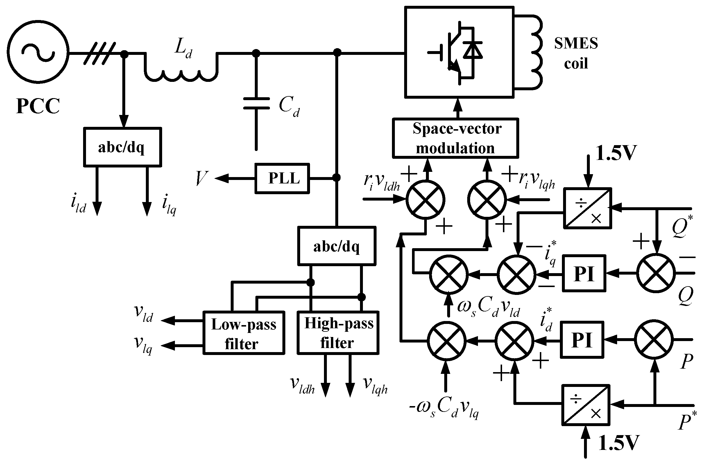
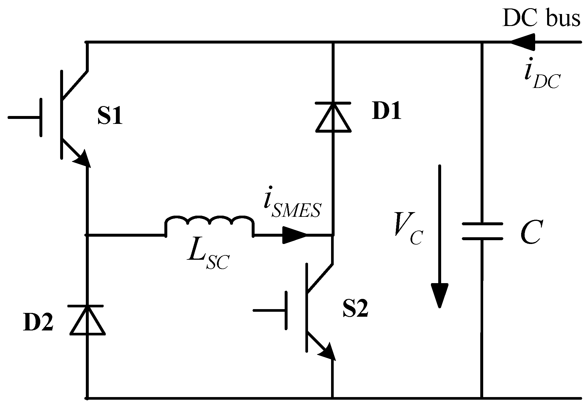
4. Structure, Control and Capacity Design of the Superconducting Magnetic Energy Storage for the Photovoltaic Generation

After the SFCL is controlled to play its role, the expected function of the SMES is to eliminate the unbalanced kinetic energy. As a result, the remaining power fluctuation during the process of the fault can be mitigated. The topology of bi-directional DC/DC converter for a superconducting magnet is shown in Figure 4. The average power of the SMES in one switching period is controlled by adjusting duty ratio (D) of the switch S1 and S2. The duty ratio can be calculated by:
P S M E S = V C ( 2 D 1 ) i S M E S
In respect to the control block diagram of the SMES unit, it is indicated in Figure 5. The power regulator section calculates the required active power and reactive power, which should be supported by the SMES unit. Then, it generates the referenced d-axis and q-axis currents for carrying out the energy compensation. From the figure, two closed-loop power controllers are used to generate the current references i d * and i q * , and the active power and reactive power tracking can be achieved. Additionally, for the grid-connected inverter which achieves the AC/DC power conversion between the SMES coil and the main network, one important issue is the voltage phase angle detection, and herein it is performed by phase locked-loop (PLL) technique based on a synchronous reference. The mathematical equations of i d * and i q * can be expressed as:
i d * = K p v ( V l d * v l d ) + K i v ( V l d * v l d ) d t
i q * = K p v ( V l q * v l q ) + K i v ( V l q * v l q ) d t
where Kpv and Kiv are the proportional and integral coefficients of the voltage controller; V l d * and V l q * denote the capacitor voltage’s d-axis and q-axis references. In Figure 5, the virtual impedance ri is constructed to generate the high-bandwidth damping currents [61]. Both the low-band width and high-bandwidth capacitor current compensation are added to the current references, namely ωsCdvld, rivldh, etc.
Since the role of the SMES is to stabilize the transient behaviors of the PV generation system, the following equations can be obtained:
P S F C L d t + P S M E S d t = P P V d t P g f d t
E S M E S > a f ( max ( P P V ( t ) P P V ( t Δ T ) ) Δ T
P S M E S > b f ( P P V , m a x P P V , m i n )
Δ P S M E S / Δ t > c f [ max ( P P V ( t ) P P V ( t Δ t ) / Δ t ]
where PSMES denotes the power being responded by the SMES; ESMES is the stored energy in the superconducting magnet; PPV is the PV generation’s output power at t; ΔT indicates the time interval of the power fluctuation; af is recorded as the coefficient of the SMES energy capacity constraint; PPV,max and PPV,min are respectively remarked as the maximum and minimum values of the PV fluctuation; bf is expressed as the coefficient of the SMES power capacity constraint; Δ P SMES is the change of the SMES power; Δ t is the time interval to assess the rate of change of the SMES power; and cf is the coefficient of the SMES power adjustment rate constraint [62]. Although the SMES is able to absorb or release energy during the transient process of the fault, the magnet current ISMES may not change abruptly, and the relationship among the magnet current, stored energy and DC bus voltage can be expressed as:
E S M E S = 0.5 L S C I S M E S 2
P S M E S = min { P * , V C I S M E S }
where P* is the power order; and LSC is the inductance of the superconducting magnet. The SMES unit’s maximum power will be also limited by the value of VCISMES. In the case of that the fault occurrence time is expressed as to, and the fault clearance time is remarked as tc, the energy which the SMES should absorb or release can be written as:
Δ E = t o t c P S M E S d t = t o t c P P V d t t o t c P g f d t t o t c P S F C L d t
According to Equation (21), the introduction of the SFCL can help to reduce the capacity requirement for the SMES. In other words, for the case that the SFCL is not applied to dissipate a certain active power, the required storage energy in the SMES which is used to reduce the power fluctuation will be relatively larger. This is a critical reason why the combined use of SFCL and SMES is selected. Otherwise, the increase of the SMES capacity means that both of the converter and the SMES coil should increase in size, and the increased cost may be more than the cost of introducing the SFCL. Assuming that the initial current in the superconducting magnet is defined as ISMES0, the magnet current’s mathematical expression will be indicated as:
I S M E S ( t ) = I S M E S 0 2 + 2 Δ E / L S C
In accordance with the Equation (19), the maximum power of the SMES can be calculated as:
P S M E S - m a x = V C I S M E S ( t ) = V C I S M E S 0 2 + 2 Δ E / L S C
To guarantee the operational efficiency of the SMES, the power PSMES at any time of the fault feeding process should meet the demand of PSMESPSMES-max. From the aforementioned theoretical derivation, the storage energy and power requirements for the SMES can be determined, and the superconducting inductance LSC can be obtained by the calculation of ΔE and ISMES-max (the critical current of the superconducting magnet).

5. Simulation Studies and Verification

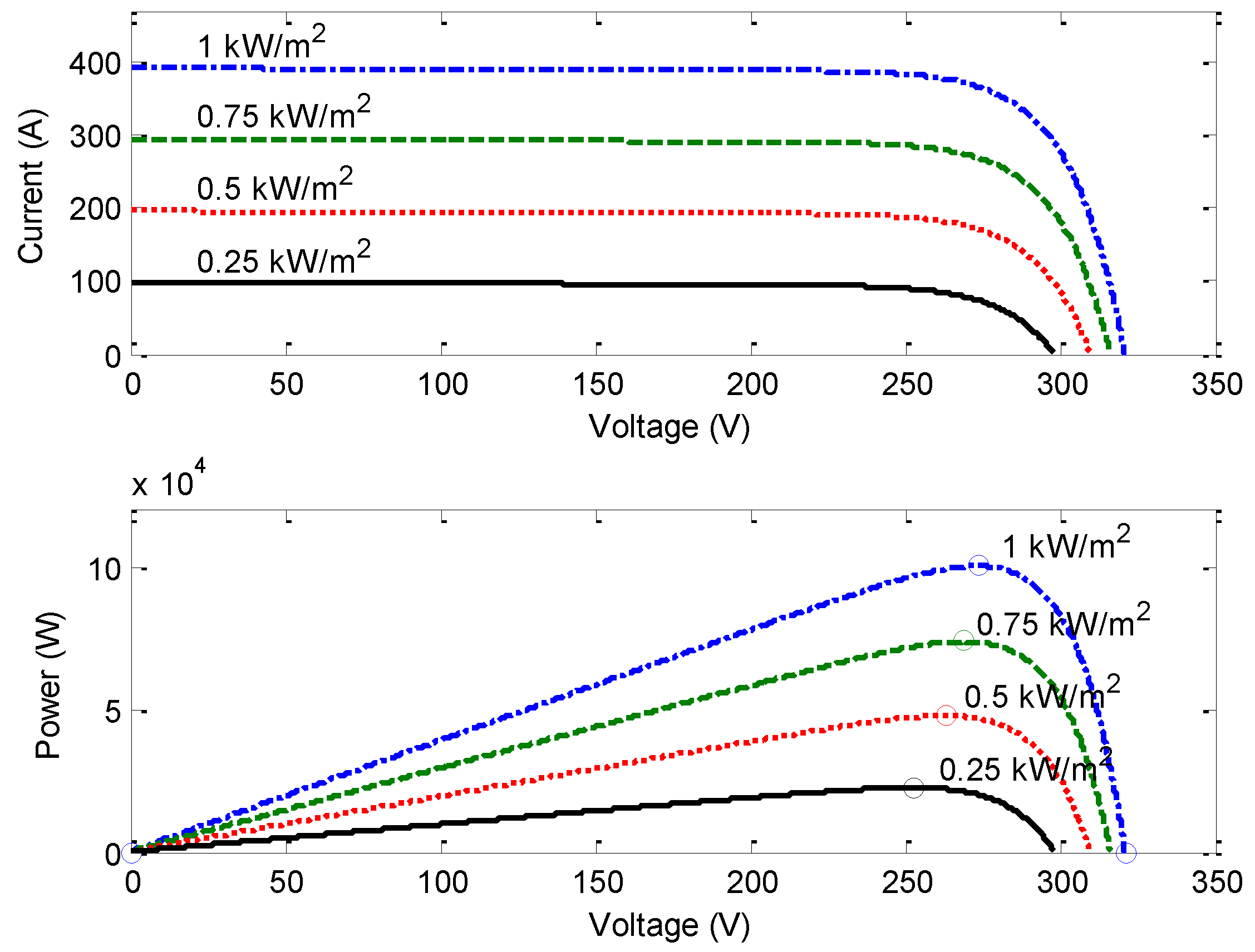
5.1. Modeling and Parameters

In order to verify the effectiveness of the coordination control and assess the transient performance of the PV generation system, a detailed simulation model corresponding to Figure 1 is built in MATLAB/SIMULINK, and the main parameters are indicated in Table 1.
In regard to the simulation model of the PV generation system [63], a description is shown as follows. The PV array is used to deliver the maximum value of 100 kW at 1000 W/m2 sun irradiance; the I-V characteristic and P-V characteristic can be shown in Figure 6; a boost converter (orange blocks) is used for increasing voltage from PV natural voltage (272 V DC at maximum power) to 500 V DC; Switching duty cycle is optimized by the MPPT controller; The voltage source converter (VSC) converts the 500 V DC to 260 V AC and keeps unity power factor; a 10 kvar capacitor bank is used for filtering harmonics produced by the VSC; a 200 kVA, 260 V/10.5 kV three-phase CT is used for connecting the PV generation system to the utility grid.
Concerning the parameters of the SFCL and the SMES, they have not been optimized further, and their selection is done according to [64,65]. From the literatures [64,65], the parameters of the two superconducting devices should have certain ranges, which are determined by their application voltage grade and current capacity. Thus, the parameters in Table 1 are mainly used to estimate the validity of the coordination control. In Section 6, a preliminary parameter optimization method is suggested for the SFCL and the SMES.
For the simulation modeling of the flux-coupling-type SFCL, the CS is simulated by an anti-parallel IGBT pairs, and the CT is simulated by a standard transformer model with self inductances and mutual inductance. As shown in Figure 7, it indicates the quench/recovery of the SC, and multiple operational segments of the SC resistance will be taken into account [66]. The SC’s operating characteristic can be expressed as:
R S C ( t ) = { 0 ( t < t 0 ) R n [ 1 exp ( t t 0 τ ) ] 1 2 ( t 0 t < t 1 ) a 1 ( t t 1 ) + b 1 ( t 1 t < t 2 ) a 2 ( t t 2 ) + b 2 ( t 2 t )
where Rn denotes the normal-state resistance of the SC; τ is the time constant. The SC’s time-domain characteristic is stated as that, t0, t1, and t2 indicate the quench-starting time, the first recovery-starting time, and the secondary recovery-starting time, respectively. a1, b1, a2 and b2 are the function coefficients, respectively. It is assumed that the SC will enter the quenching state within 4 ms, and after the fault is removed, the SC’s recovery time is set as 0.5 s to cooperate with the reclosing.
In respect to the modeling of the SMES unit, it includes the coordinated controller, LCL filter, three-phase half-bridge VSC, chopper and superconducting magnet, and its main structure can be according to [67]. The VSC and the chopper use the standard models from the MATLAB model library, and the superconducting magnet is simulated by a non-resistive inductance model.
For the specific FRT code which the PV generation system should follow, the Denmark code is selectively used in the simulations [68]. In the case of that the grid voltage drops to 20% of the nominal level, the PV generation system should remain the grid-connected state for a duration of 150 ms.

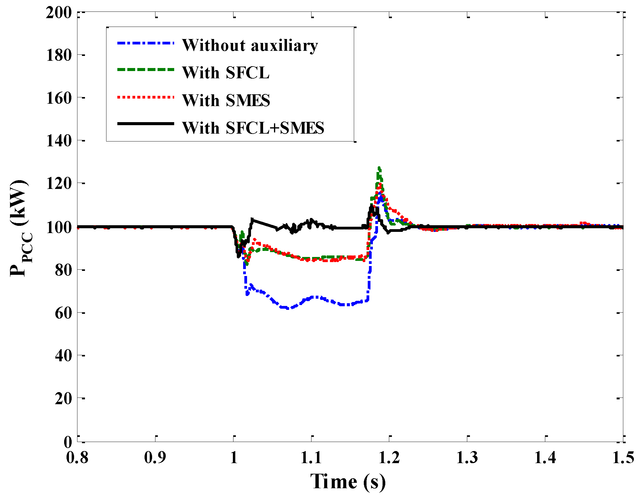
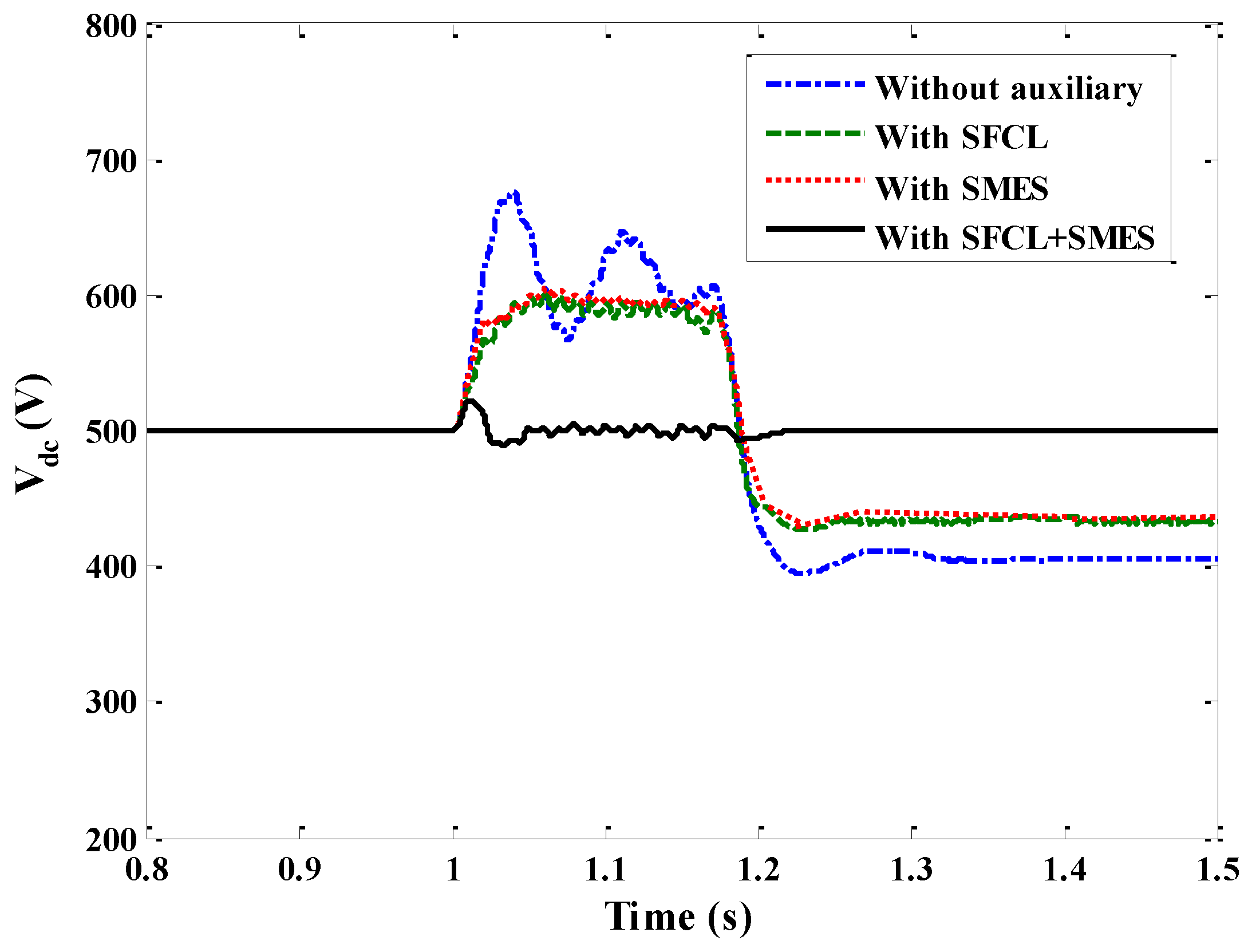
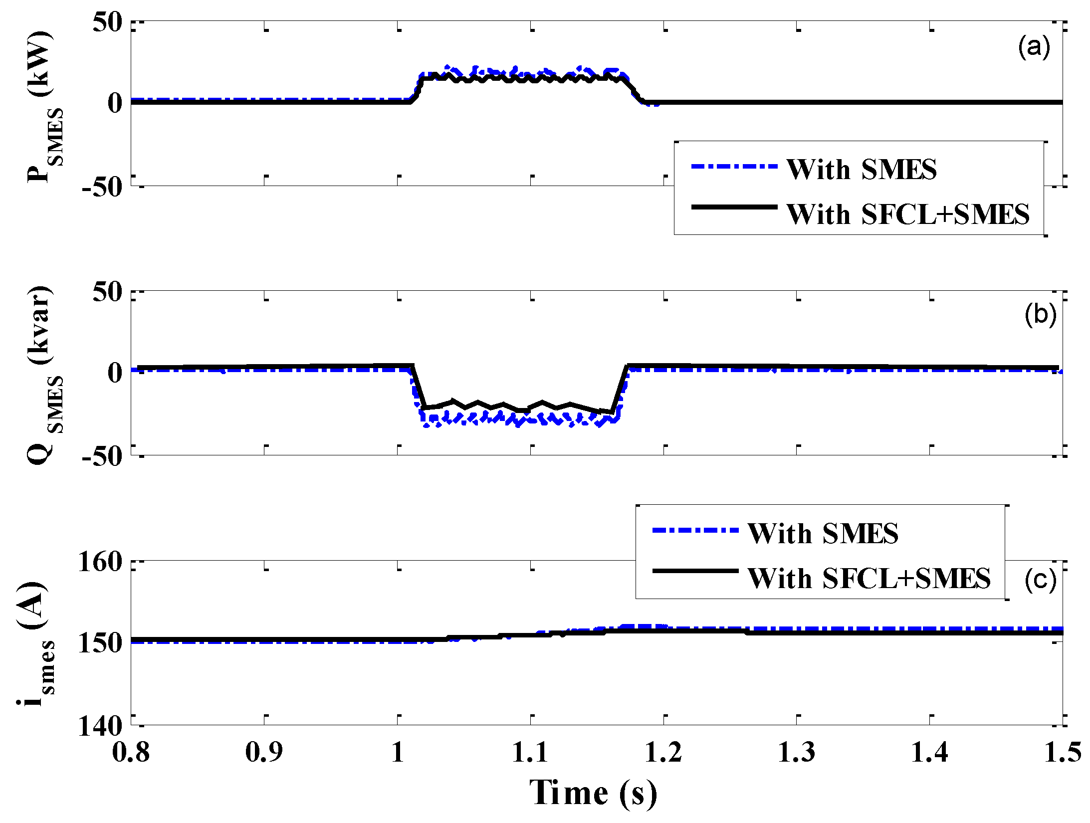
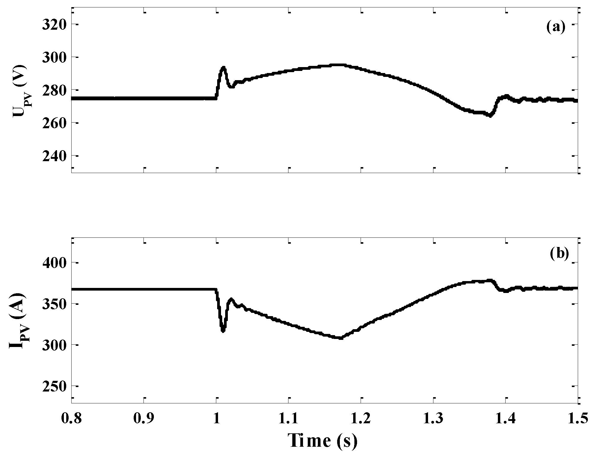
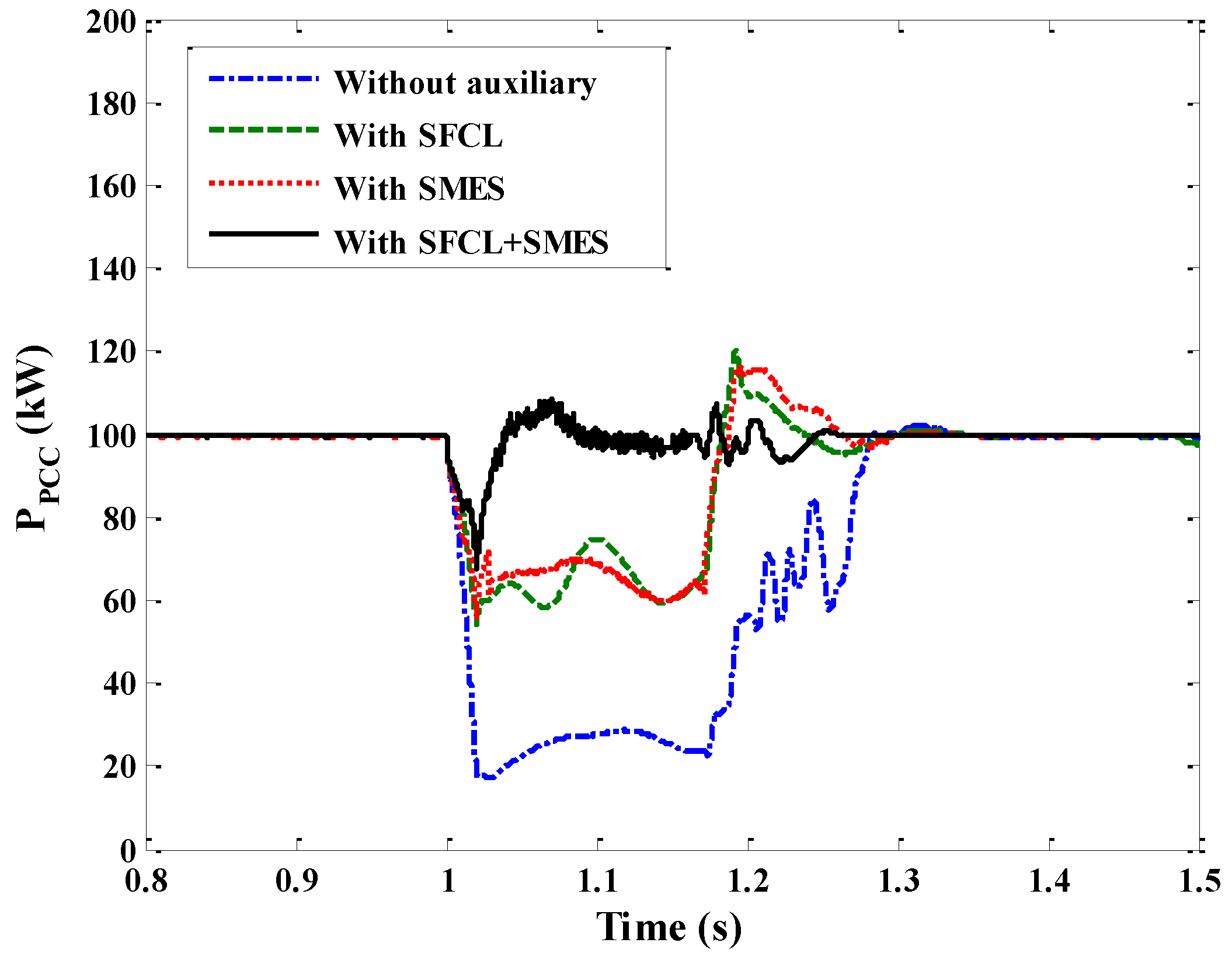
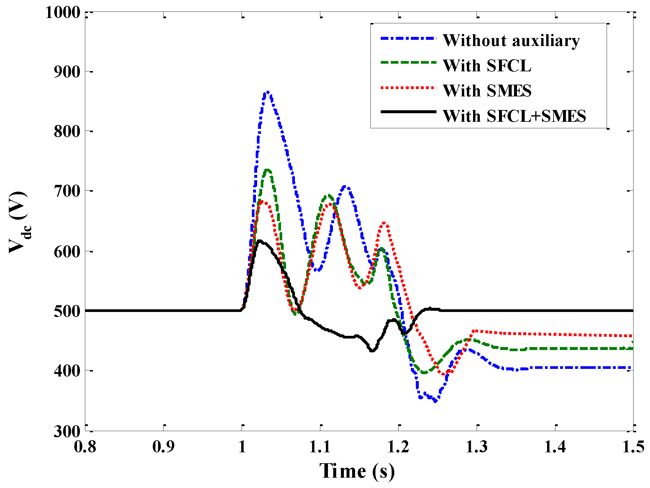
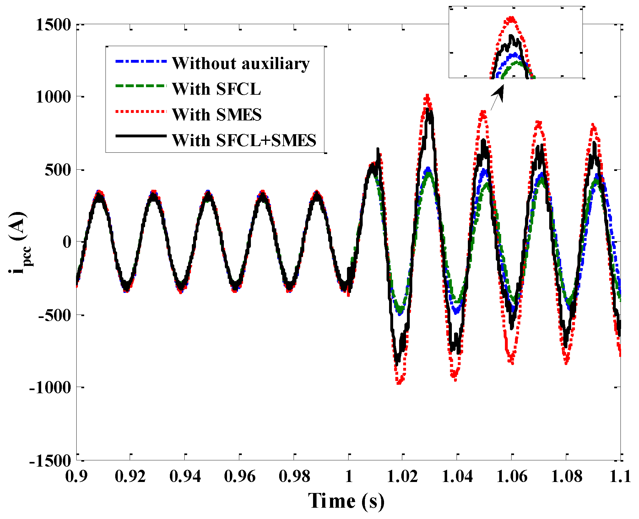
5.2. Simulation Study of the Symmetrical Fault

Supposing that a three-phase short-circuit fault happens on the main network, the detailed simulation conditions are defined as that: the fault occurrence time is set as t = 1 s; the fault resistance is Rg = 1.5 Ω; the fault duration is 170 ms.
Figure 8 shows the three-phase voltage characteristics of the PV system under symmetrical fault conditions. During the fault feeding process, the PV generation system’s output voltage coupled to the AC side will decrease from 200 V to 36 V (peak value), and the rate of decline in the voltage can reach to 82%. Concerning this fault case, the PV system cannot meet the FRT code, and it will be enforcedly separated from the main network.
Figure 9 shows the PV voltage and PV current profiles under the symmetrical fault. The PV voltage will slightly increase when the fault is feeding, and it will return to the nominal level after the fault is removed. The recovery time of the PV voltage is about 230 ms. Since the power of the PV panels is supposed to be constant during the time-scale of several seconds, the variation trend of the PV current is exactly reverse to that of the PV voltage.
To verify the capability of the proposed coordination approach more comprehensively, four different kinds of simulation cases are considered, corresponding to that without auxiliary, with SFCL, with SMES, and with SFCL-SMES, respectively. In the four simulation cases, MPPT control is disabled during the fault, and considering the combination of without MPPT control and with SFCL-SMES, the transient performance of the PV generation system may be improved more efficiently.
Note that, although the comparison of the SFCL-SMES and the other traditional devices is not specifically given, the comparison of the four cases can be still meaningful. From the viewpoint of introducing a real or an equivalent current-limiting impedance into the main circuit, the effect of a SFCL is similar to that of a traditional FCL or a series compensator, and their major differences include topological structure, operation loss, response speed and economics. From the viewpoint of achieving a fast control of active and reactive power, the function of a SMES is similar to that of the other energy storage device (such as SuperCapacitors), and their major differences include energy storage materials, device configuration, lift cycle, response time and economics.
Therefore, if only the essential functions such as the current-limiting impedance and power control are taken into account, the comparison results of this paper can provide certain reference significance. If a more comprehensive comparison should be done to get more specific conclusions, the structural design, parameter optimization, cost analysis and economic evaluation need to be carried out. In a sense, they may be out of the scope of this paper.
Figure 10 shows the characteristics of the exchange power at the PCC under the symmetrical fault. In the case of without auxiliary, the exchange power will decrease from 100 kW to 25 kW, and the 75% average drop in the exchange power can be obtained. From this figure, the power compensation effect of only using the SFCL is similar to that of only using the SMES, and the PCC power can be approximatively improved to the level of 70 kW. Obviously, the coordination control of the SFCL-SMES can cause the best compensation effect. During the symmetrical fault, the use of the SFCL-SMES can make the PCC exchange power be maintained at 96 kW, and the calculated drop rate is merely 4%. In addition, the use of the SFCL-SMES can help to accelerate the recovery of the PCC power, and the transient duration can be reduced. In consideration of these positive effects, the improvement of the exchange power can well enhance the utilization efficiency of the PV generation system.
Figure 11 shows the voltage fluctuation at the PCC (RMS value) under the symmetrical fault. According to the results, the single use of the SMES can just improve the PCC voltage to 35.2% of the nominal level, although it provides the reactive current support by injecting the reactive power. Since the working principle of the SFCL is to insert the series impedance, the voltage compensation effect of the SFCL is better that of the SMES, and the PCC voltage can return to 49.1% of the nominal level. Regarding the coordination control of the SFCL-SMES, it absorbs the two devices’ merits and makes the voltage be increased to 55.6% of the nominal level, and the PV generation system can undoubtedly achieve the FRT operation.
Figure 12 shows the overvoltage over the DC-link of the PV generation system. In corresponding to the conditions without auxiliary, with SFCL, with SMES, and with SFCL-SMES, the DC-link overvoltage’s peak value will respectively reach to 865, 734, 680 and 608 V. In practice, the over-voltage protection may trip the inverter when DC voltage exceeds a threshold, probably around 900 V. When the inverter is no longer able to control the DC voltage, the boost converter should limit the output DC voltage to a certain safe limit. Due to the use of the SFCL-SMES, not only the fluctuation range of the DC-link overvoltage, but also the fluctuation duration can be well suppressed. In other words, the whole fluctuation process can be smoothed, as a result of avoiding catastrophic failures to the capacitor.
Figure 13 indicates the PCC current under the symmetrical fault. From the demonstrated results, using the SFCL will limit the PCC current to a certain extent, but using the SMES will increase the PCC current due to the reactive current support. As the combination of these two opposing effects, the coordinated use of the SFCL and the SMES will play a compromising role in controlling the PCC current.
Regarding the SMES unit’s active power, reactive power and magnet current under the symmetrical fault, the simulation results are indicated in Figure 14. It is found that introducing the SFCL can reduce the capacity requirement for the SMES, and this simulation conclusion is in agreement with the theoretical analysis. The SMES unit will absorb the active power and release the reactive power under the fault, and the magnet current is maintained at a stable level. Considering these crucial operation characteristics of the PCC voltage, PCC power, PCC current and DC-link overvoltage, the coordinated control of the SFCL-SMES can be regarded as an efficient and feasible approach to improve the PV system’s transient performance under the symmetrical fault.

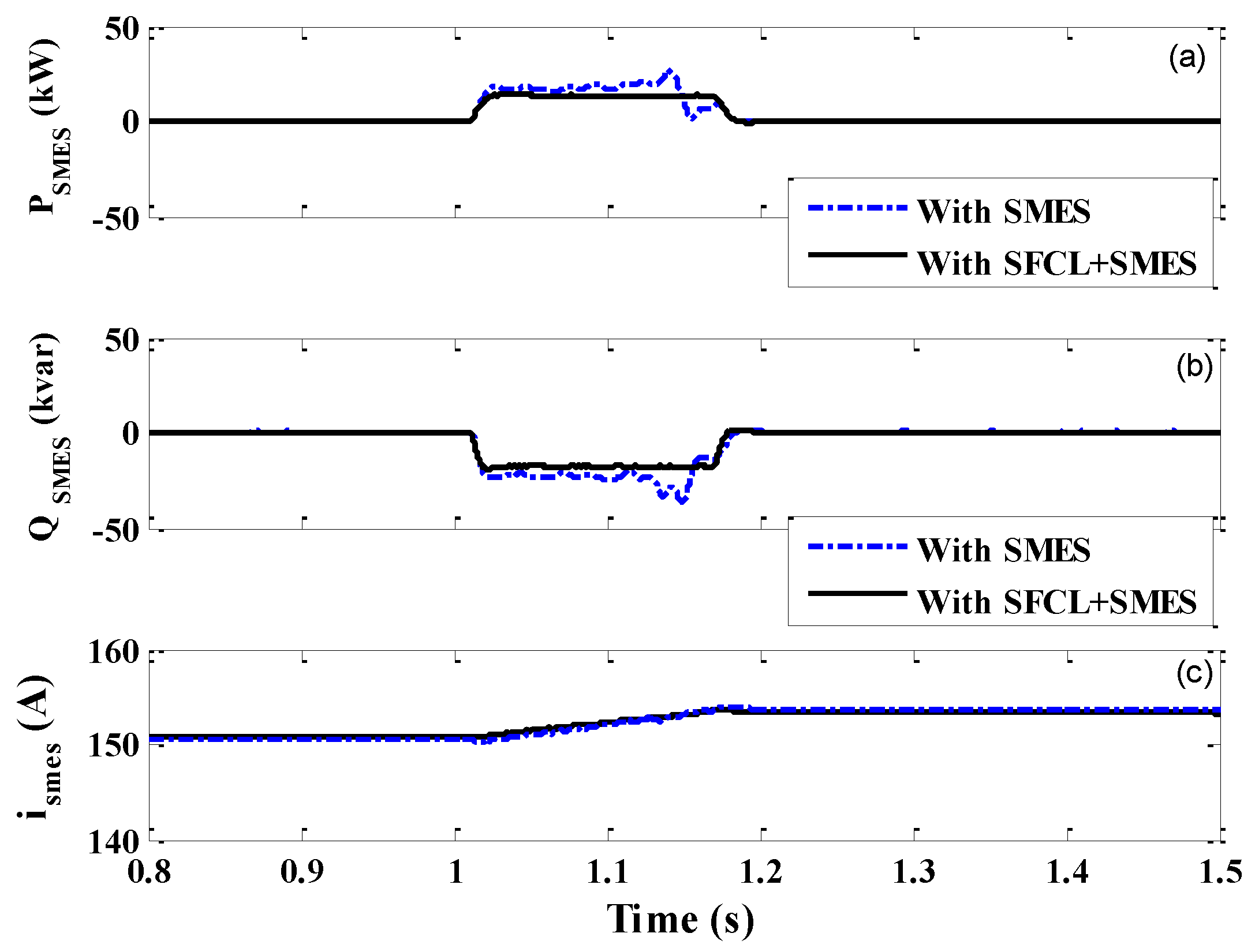
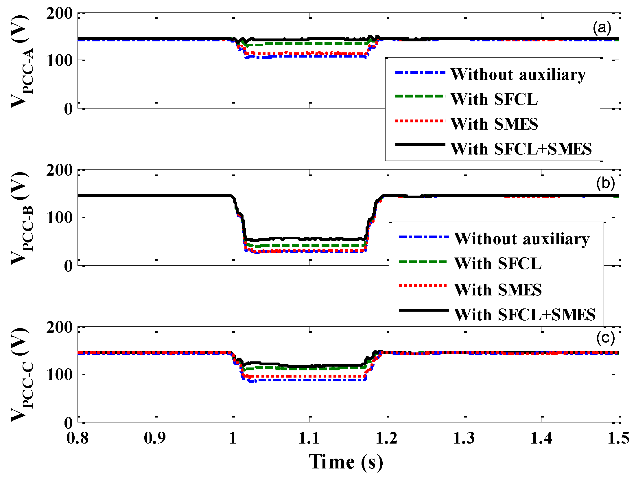
5.3. Simulation Study of the Asymmetrical Fault

In order to study the transient behaviors of the PV generation system under the asymmetrical fault, a double-phase (A-phase and B-phase) ground fault is supposed to happen on the main network. MPPT control is still disabled during the fault, and the other simulation conditions are the same as the symmetrical fault.
Figure 15 shows the PV generation system’s three-phase voltages under the asymmetrical fault. Based on the simulation results, the three-phase unbalance will be very obvious. Among the three phase voltages, the B-phase voltage will have the lowest amplitude level. As affected by the fault, the B-phase voltage’s peak value will decrease from 200 V to 40 V, and the calculated rate of decline in the voltage can reach to 80%. In respect to the A-phase and C-phase voltages, their rates of decline are about 17.5% and 32.6%, respectively.
Figure 16 shows the PV current and PV voltage profiles under the asymmetrical fault. As the asymmetrical fault is usually less serious than the symmetrical fault, the fluctuations of the PV voltage and PV current under the asymmetrical fault will be relatively smaller, and the recovery time of the PV voltage is reduced to 120 ms.
Figure 17, Figure 18 and Figure 19 show the PV generation system’s PCC power, PCC voltage and DC-link voltage under the asymmetrical fault. In a similar way, the four different cases are taken into consideration, and they are corresponding to that without auxiliary, with SFCL, with SMES, and with SFCL-SMES, respectively. In the event of without auxiliary, the PCC power will decrease from 100 kW to 70 kW, and the use of the SFCL-SMES can maintain the power balance and reduce the power fluctuation as best as it can.
In regard to the PCC voltage sag during the fault, the use of the SFCL-SMES can make the B-phase voltage sag be limited to 59% of the nominal level. Meanwhile, the A-phase and C-phase voltage sags can be also compensated to a certain extent. Note that, since the SMES unit’s major function is to adjust its active and reactive power for eliminating the power fluctuation in this study, its specific effect on reducing the imbalance in the three-phase voltages may have a margin for improvement. As one of the future works, the control of the positive, negative and zero sequence components of the reactive current may be appreciatively introduced, so as to make that the SFCL-SMES can deal with the asymmetrical fault and mitigate the three-phase imbalance more efficiently.
In light of the dynamic response characteristics of the DC-link overvoltage under the asymmetrical fault, its peak value will respectively increase to 680 V, 600 V, 598 V and 522 V in corresponding to the conditions without auxiliary, with SFCL, with SMES, and with SFCL-SMES. It is found that the DC-link voltage has the best smoothness properties when the SFCL-SMES plays its expected role.
Figure 20 indicates the operation characteristics of the SMES unit under the asymmetrical fault. In accordance with a similar way under the symmetrical fault, the SMES unit absorbs the active power and releases the reactive power under the asymmetrical fault. It should be noted that the specific power requirements for the SMES unit under the two faults are different. Regarding the symmetrical fault, the active and reactive power orders for the SMES unit are 24.9 kW and 40 kvar, respectively. Concerning the asymmetrical fault, the active and reactive power orders for the SMES unit will be reduced to 18 kW and 30 kvar, respectively. In a sense, the optimization design of the SMES capacity will be critical, and the power requirements under different fault conditions may be fully taken into account.

6. Optimization Method for the Superconducting Fault Current Limiter–Superconducting Magnetic Energy Storage

From the aforementioned simulation results, the coordinated control of the SFCL-SMES is able to play an efficient role in improving the PV generation system’s transient performance under the fault conditions. In principle, the introduction of these two superconducting devices will increase the investment costs, and meanwhile it should be noted that, the enhancement of the PV system’s transient performance can as well cause some considerable benefits, such as the reduction of the DC-link overvoltage for protecting the capacitor, improvement of the PCC power for ensuring the utilization efficiency of renewable energy, stabilization of the supply load for avoiding the energy outage. All of these benefits resulted from the SFCL-SMES can translate into economic values [69]. Therefore, it is meaningful and valuable to carry out the optimization design of the two superconducting devices, and studying how to guarantee the techno-economics of the SFCL-SMES may become critical. In this section, a preliminary parameter optimization method is suggested.
In respect to the SFCL optimization, it has two optimization objectives. One is the kinetic energy in the DC-link capacitance of the PV system during the faults, and the other is the energy loss of the flux-coupling-type SFCL. Therefore, the decrease of the fault current, the alleviation of the DC-link overvoltage, and the compensation of the PCC voltage sag can be obtained. The FRT capability enhancement of the PV generation can be expected.
As studied in the Equation (2), the stored kinetic energy of the DC-link capacitance during the fault can be expressed as:
E D C - l i n k = t 0 t c ( P P V P g f ) d t = t 0 t c P D C 1 d t = 1 2 C D C 1 ( V D C 1 f 2 V D C 1 2 )
From the expression of the SFCL’s current-limiting impedance, its energy loss during the fault can be calculated as:
E S F C L = t o t c P S F C L d t = t o t c i 2 ( t ) R S C d t
where i(t) is the current flowing through the SC.
After the suggested SFCL plays the role, the SMES unit is used to eliminate the unbalanced kinetic energy. Consequently, the remaining power fluctuation of the PV generation system can be mitigated. For the SMES unit, the minimization of the integral absolute error (IAE) of the power deviation at the PCC (ΔPPCC) is regarded as the optimization objective, and it can be expressed as:
I A E = t i t s | Δ P P C C | d t
where ti is the initial time of simulation analysis; ts is the stop time of simulation analysis.
Considering that the SMES unit’s initial stored energy is expressed as ESMES-ini = 0.5I2SMES-iniLSC, the initial magnet current ISMES-ini and the magnet inductance LSC can be optimized, so as to make the stored energy be enough to deal with all of the fault cases.
In combination of the aforementioned four optimization objectives, the completed optimization function of the SFCL-SMES can be defined as:
M i n i m i z e E D C - l i n k + E S F C L + t i t s | Δ P P C C | d t + E S M E S i n i
Subject to:
(1)
400 V ≤ VDC1-f ≤ 600 V (range of the DC-link voltage)
(2)
0.01 Ω≤ RSC ≤ 5 Ω (range of the SC resistance)
(3)
0.01 H≤ LSC≤ 10 H (range of the SMES coil inductance)
(4)
0.1 A≤ ISMES0 ≤ 2 kA (range of the SMES initial coil current)
(5)
0.5ISMES0ISMES ≤ 1.5ISMES0 (range of the SMES coil current)
(6)
0.0001 ≤ KPk, KQk ≤ 100 (range of the SMES power controller gain)
(7)
0.0001 ≤ TPk, TQk ≤ 1 (range of the SMES power controller time constant)
The control effect of the optimized SFCL and SMES can be compared to the optimized SFCL or the optimized SMES.
The optimized parameters of the SFCL are performed by:
M i n i m i z e α E D C - l i n k + E S F C L 0 α 1 Subject   to   constraints   ( 1 ) , ( 2 )
The optimized parameters of the SMES are conducted by:
M i n i m i z e ( 1 α ) E D C - l i n k + t i t s | Δ P P C C | d t + E S M E S i n i 0 α 1 Subject   to   constraints   ( 1 ) , ( 3 ) , ( 4 ) , ( 5 ) , ( 6 ) , ( 7 )
For the sake of solving the optimization problem, different intelligent algorithms [70,71,72,73] can be used to achieve the optimization results. The comparison of multiple intelligent algorithms can help to enhance the credibility of the optimization results, and further the assessment of the cost and economic performance will become more reliable. Note that, the expected purpose of this section is to show a preliminary optimization idea and provide a possible research direction for our follow-up works. In consideration of the capital and maintenance costs caused by the superconducting materials and cryocooler, it is significant to improve the economics of the SFCL-SMES and promote the real application. The detailed optimization and design will be carried out in the near future, and the related results will be reported in later articles.

7. Conclusions

This paper proposes and studies the coordinated control of a flux-coupling-type SFCL and a SMES unit, so as to improve the transient performance of a grid-connected PV generation system under the symmetrical and asymmetrical faults. Both of theoretical derivation and simulation analysis are carried out. On the basis of that MPPT control is disabled during the faults, four different cases including without auxiliary, only with SFCL, only with SMES, and with SFCL-SMES are compared in detail. Moreover, a preliminary parameter optimization method is suggested for the SFCL-SMES. According to the demonstrated results, the authors draw the following conclusions:
(1)
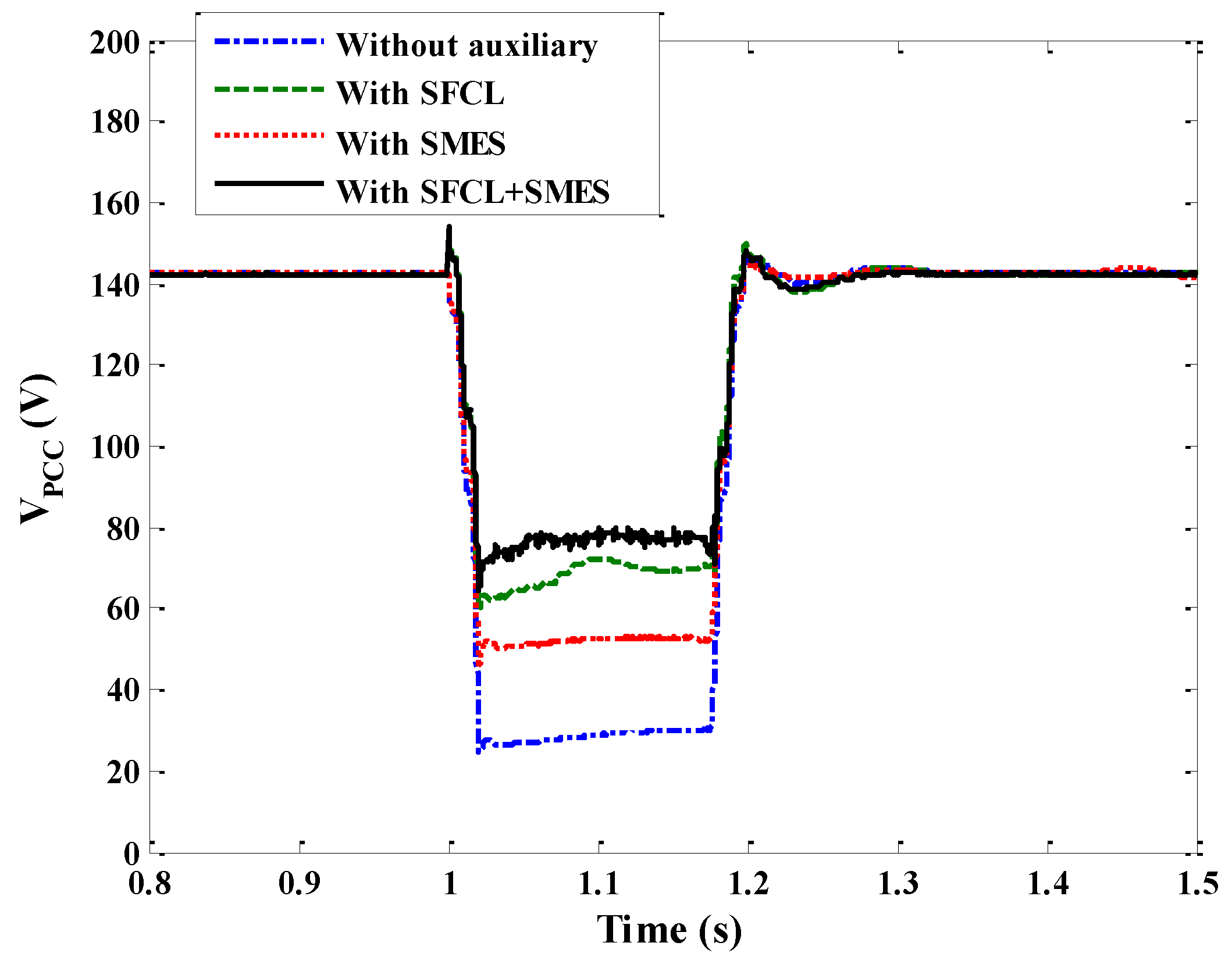
The single use of the SFCL has a better effect on limiting the fault current, but weaker effects on the power compensation and DC overvoltage inhibition. The single use of the SMES can provide flexible power compensation, but it has a larger capacity requirement and a weaker effect on improving the voltage sag. In contrast, the coordinated control of the SFCL and the SMES can offer the best comprehensive performance. The combination of without MPPT and with SFCL-SMES can more efficiently improve the PCC voltage sag, inhibit the DC-link overvoltage and alleviate the PV system’s power fluctuation. Thus, the PV system’s robustness against short-circuit faults can be well strengthened.
(2)
Regarding the SFCL-SMES, its specific effect on reducing the imbalance in the three-phase fault voltages may have a margin for improvement. As one of the future works, the control of the positive, negative and zero sequence components of the reactive current may be appreciatively introduced, so as to make the SFCL-SMES be able to deal with the asymmetrical fault and mitigate the three-phase imbalance more efficiently.
(3)
Since the transient characteristics of the PV generation system will be closely related to the fault type, no matter the SFCL’s effects on the fault current, DC-link overvoltage and PCC voltage sag, or the power requirements for the SMES unit under the symmetrical and asymmetrical faults are different. In the follow-up works, the detailed optimization design of the SFCL-SMES capacity will be carried out, and more different conditions including fault resistance, fault duration, and fault location will be taken into account.
In respect to the integrated use of the two superconducting power devices, the techno-economics will be carefully evaluated, and it is expected that the practical application of the SFCL-SMES in the renewable energy systems will come true in the near future.

Acknowledgments

This work was supported in part by the National Natural Science Foundation of China (51507117), and Wuhan Planning Projects of Science and Technology (2013072304010827).

Author Contributions

Lei Chen helped design the study, analyze the data, and write the manuscript. Hongkun Chen helped conduct the study. Jun Yang helped analyze the data. Yanjuan Yu helped draw the figure. Kaiwei Zhen helped draft the manuscript. Yang Liu helped conduct the simulation analysis. Li Ren helped edit the manuscript.

Conflicts of Interest

The authors declare no conflict of interest.

References

  1. Kies, A.; Schyska, B.U.; von Bremen, L. Curtailment in a highly renewable power system and its effect on capacity factors. Energies 2016, 9, 510. [Google Scholar] [CrossRef]
  2. Leccisi, E.; Raugei, M.; Fthenakis, V. The Energy and environmental performance of ground-mounted photovoltaic systems—A timely update. Energies 2016, 9, 622. [Google Scholar] [CrossRef]
  3. Elserougi, A.; Massoud, A.M.; Abdel-Khalik, A.S.; Ahmed, S. Three-wire bipolar high-voltage direct current line using an existing single-circuit high-voltage alternating current line for integrating renewable energy sources in multiterminal DC networks. IET Renew. Power Gener. 2016, 10, 370–379. [Google Scholar] [CrossRef]
  4. Baker, K.; Guo, J.; Hug, G.; Li, X. Distributed MPC for efficient coordination of storage and renewable energy sources across control areas. IEEE Trans. Smart Grid 2016, 7, 992–1001. [Google Scholar] [CrossRef]
  5. Miret, J.; Castilla, M.; Camacho, A.; de Vicuña, L.G.; Matas, G. Control scheme for photovoltaic three-phase inverters to minimize peak currents during unbalanced grid-voltage sags. IEEE Trans. Power Electron. 2012, 27, 4262–4271. [Google Scholar] [CrossRef]
  6. Gu, B.; Sheng, V.S.; Wang, Z.; Ho, D.; Osman, S.; Li, S. Incremental learning for ν-support vector regression. Neural Netw. 2015, 67, 140–150. [Google Scholar] [CrossRef] [PubMed]
  7. Zhang, Y.; Sun, X.; Wang, B. Efficient algorithm for k-barrier coverage based on integer linear programming. China Commun. 2016, 13, 16–23. [Google Scholar] [CrossRef]
  8. Fu, Z.; Sun, X.; Liu, Q.; Zhou, L.; Shu, J. Achieving efficient cloud search services: Multi-keyword ranked search over encrypted cloud data supporting parallel computing. IEICE Trans. Commun. 2015, 98, 190–200. [Google Scholar] [CrossRef]
  9. Ma, T.; Zhou, J.; Tang, M.; Tian, Y.; Al-Dhelaan, A.; Al-Rodhaan, M.; Lee, S. Social network and tag sources based augmenting collaborative recommender system. IEICE Trans. Inf. Syst. 2015, 98, 902–910. [Google Scholar] [CrossRef]
  10. Yan, B.; Wang, B.; Zhu, L.; Liu, H.; Liu, Y.; Ji, X.; Liu, D. A novel, stable, and economic power sharing scheme for an autonomous microgrid in the energy internet. Energies 2015, 8, 12741–12764. [Google Scholar] [CrossRef]
  11. Xia, Z.; Wang, X.; Sun, X.; Wang, Q. A secure and dynamic multi-keyword ranked search scheme over encrypted cloud data. IEEE Trans. Parallel Distr. Syst. 2015, 27, 340–352. [Google Scholar] [CrossRef]
  12. Fu, Z.; Ren, K.; Shu, J.; Sun, X.; Huang, F. Enabling personalized search over encrypted outsourced data with efficiency improvement. IEEE Trans. Parallel Distr. Syst. 2016, 27, 2546–2559. [Google Scholar] [CrossRef]
  13. Lee, G.; Kim, H. Green small cell operation of ultra-dense networks using device assistance. Energies 2016, 9, 1065. [Google Scholar] [CrossRef]
  14. Chen, X.; Yin, X.; Yu, B.; Zhang, Z. Communication channel reconstruction for transmission line differential protection: System arrangement and routing protocol. Energies 2016, 9, 893. [Google Scholar] [CrossRef]
  15. Fu, Z.; Wu, X.; Guan, C.; Sun, X.; Ren, K. Toward efficient multi-keyword fuzzy search over encrypted outsourced data with accuracy improvement. IEEE Trans. Inf. Forensics Secur. 2016, 11, 2706–2716. [Google Scholar] [CrossRef]
  16. Xia, Z.; Wang, X.; Zhang, L.; Qin, Z.; Sun, X.; Ren, K. A privacy-preserving and copy-deterrence content-based image retrieval scheme in cloud computing. IEEE Trans. Inf. Forensics Secur. 2016, 11, 2594–2608. [Google Scholar] [CrossRef]
  17. Yuan, C.; Sun, X.; Lv, R. Fingerprint liveness detection based on multi-scale LPQ and PCA. China Commun. 2016, 13, 60–65. [Google Scholar] [CrossRef]
  18. Zhou, Z.; Wang, Y.; Jonathan Wu, Q.M.; Yang, C.N.; Sun, X. Effective and efficient global context verification for image copy detection. IEEE Trans. Inf. Forensics Secur. 2017, 12, 48–63. [Google Scholar] [CrossRef]
  19. Yang, Y.; Blaabjerg, F.; Wang, H. Low-voltage ride-through of single-phase transformerless photovoltaic inverters. IEEE Trans. Ind. Appl. 2014, 50, 1942–1952. [Google Scholar] [CrossRef]
  20. Coster, E.J.; Myrzik, J.M.A.; Kruimer, B.; Kling, W.L. Integration issues of distributed generation in distribution grids. Proc. IEEE 2011, 99, 28–39. [Google Scholar] [CrossRef]
  21. Hudson, R.; Heilscher, G. PV grid integration—System management issues and utility concerns. Energy Procedia 2012, 25, 82–92. [Google Scholar] [CrossRef]
  22. Yang, Y.; Blaabjerg, F. Low voltage ride-through capability of a single-stage single-phase photovoltaic system connected to the low voltage grid. Int. J. Photoenergy 2013, 2013. [Google Scholar] [CrossRef]
  23. Zhang, W.; Remon, D.; Cantarellas, A.M.; Rodriguez, P. A unified current loop tuning approach for grid-connected photovoltaic inverters. Energies 2016, 9, 723. [Google Scholar] [CrossRef]
  24. Hao, T.; Feng, G.; Guoqing, H.; Li, G. Low voltage ride through of two-stage photovoltaic inverter with enhanced operational performance. In Proceedings of the 2012 Twenty-Seventh Annual IEEE Applied Power Electronics Conference and Exposition (APEC), Orlando, FL, USA, 5–9 February 2012.
  25. Moursi, M.S.E.; Xiao, W.; Jim, L.K.J. Fault ride through capability for grid interfacing large scale PV power plants. IET. Renew. Power. Gener. 2013, 7, 1027–1036. [Google Scholar] [CrossRef]
  26. Bae, Y.; Vu, T.K.; Kim, R.Y. Implemental control strategy for grid stabilization of grid-connected PV system based on German grid code in symmetrical low-to-medium voltage network. IEEE Trans. Energy Convers. 2013, 28, 619–631. [Google Scholar] [CrossRef]
  27. Mitra, M.; Josep, P.; Vassilios, G.A. Single- and two-stage inverter-based grid-connected photovoltaic power plants with ride-through capability under grid faults. IEEE Trans. Sustain. Energy 2015, 6, 1150–1159. [Google Scholar]
  28. Neves, F.A.S.; Carrasco, M.; Mancilla-David, F.; Azevedo, G.M.S.; Santos, V.S. Unbalanced grid fault ride-through control for single-stage photovoltaic inverters. IEEE Trans. Power Electron. 2016, 31, 3338–3347. [Google Scholar] [CrossRef]
  29. Ding, G.; Gao, F.; Tian, H.; Ma, C.; Chen, M.; He, G.; Liu, Y. Adaptive DC-link voltage control of two-stage photovoltaic inverter during low voltage ride-through operation. IEEE Trans. Power Electron. 2016, 31, 4182–4194. [Google Scholar] [CrossRef]
  30. Tian, H.; Gao, F.; Ma, C. Novel low voltage ride through strategy of single-stage grid-tied photovoltaic inverter with supercapacitor coupled. In Proceedings of the 2012 7th International Power Electronics and Motion Control Conference (IPEMC), Harbin, China, 2–5 June 2012.
  31. Yang, F.; Yang, L.; Ma, X. An advanced control strategy of PV system for low-voltage ride-through capability enhancement. Sol. Energy 2014, 109, 24–35. [Google Scholar] [CrossRef]
  32. Rauf, A.M.; Khadkikar, V. Integrated photovoltaic and dynamic voltage restorer system configuration. IEEE Trans. Sustain. Energy 2015, 6, 400–410. [Google Scholar] [CrossRef]
  33. Hossain, M.K.; Ali, M.H. Transient stability augmentation of PV/DFIG/SG-based hybrid power system by nonlinear control-based variable resistive FCL. IEEE Trans. Sustain. Energy 2015, 6, 1638–1649. [Google Scholar] [CrossRef]
  34. Hossain, M.K.; Ali, M.H. Transient stability augmentation of PV/DFIG/SG-based hybrid power system by parallel-resonance bridge fault current limiter. Electr. Power Syst. Res. 2016, 130, 89–102. [Google Scholar] [CrossRef]
  35. Kang, B.-K.; Kim, S.-T.; Bae, S.-H.; Park, J.-W. Effect of a SMES in power distribution network with PV system and PBEVs. IEEE Trans. Appl. Supercond. 2013, 23. [Google Scholar] [CrossRef]
  36. Kang, B.-K.; Kim, S.-T.; Bae, S.-H.; Park, J.-W. Application of SMES and grid code compliance to wind/photovoltaic generation system. IEEE Trans. Appl. Supercond. 2013, 23. [Google Scholar] [CrossRef]
  37. Kreeumporn, W.; Ngamroo, I. Optimal superconducting coil integrated into PV generators for smoothing power and regulating voltage in distribution system with PHEVs. IEEE Trans. Appl. Supercond. 2016, 26. [Google Scholar] [CrossRef]
  38. Ebrahimpour, M.; Vahidi, B.; Hosseinian, S.H. A hybrid superconducting fault current controller for DG networks and microgrids. IEEE Trans. Appl. Supercond. 2013, 23. [Google Scholar] [CrossRef]
  39. Chen, L.; Deng, C.; Guo, F.; Tang, Y.; Shi, J.; Ren, L. Reducing the fault current and overvoltage in a distribution system with distributed generation units through an active type SFCL. IEEE Trans. Appl. Supercond. 2014, 24. [Google Scholar] [CrossRef]
  40. Zheng, F.; Deng, C.; Chen, L.; Li, S.; Liu, Y.; Liao, Y. Transient performance improvement of microgrid by a resistive superconducting fault current limiter. IEEE Trans. Appl. Supercond. 2015, 25. [Google Scholar] [CrossRef]
  41. Xue, S.; Gao, F.; Sun, W.; Li, B. Protection principle for a DC distribution system with a resistive superconductive fault current limiter. Energies 2015, 8, 4839–4852. [Google Scholar] [CrossRef]
  42. Oliveira, F.; Amorim, A.; Encarnação, L.; Fardin, J.; Orlando, M.; Silva, S.; Simonetti, D. Enhancing LVRT of DFIG by using a superconducting current limiter on rotor circuit. Energies 2016, 9, 16. [Google Scholar] [CrossRef]
  43. Elshiekh, M.E.; Mansour, D.-E.A.; Azmy, A.M. Improving fault ride-through capability of DFIG-based wind turbine using superconducting fault current limiter. IEEE Trans. Appl. Supercond. 2013, 23. [Google Scholar] [CrossRef]
  44. Hossain, M.M.; Ali, M.H. Transient stability improvement of doubly fed induction generator based variable speed wind generator using DC resistive fault current limiter. IET Renew. Power Gener. 2016, 10, 150–157. [Google Scholar] [CrossRef]
  45. Zou, Z.C.; Chen, X.Y.; Li, C.S.; Xiao, X.Y.; Zhang, Y. Conceptual design and evaluation of a resistive-type SFCL for efficient fault ride through in a DFIG. IEEE Trans. Appl. Supercond. 2016, 26. [Google Scholar] [CrossRef]
  46. Rodríguez, A.; Huerta, F.; Bueno, E.J.; Rodríguez, F.J. Analysis and performance comparison of different power conditioning systems for SMES-based energy systems in wind turbines. Energies 2013, 6, 1527–1553. [Google Scholar] [CrossRef]
  47. Zhang, N.; Gu, W.; Yu, H.; Liu, W. Application of coordinated SOFC and SMES robust control for stabilizing tie-line power. Energies 2013, 6, 1902–1917. [Google Scholar] [CrossRef]
  48. Shi, X.; Wang, S.; Yao, W.; Waqar, A.; Zuo, W.; Tang, Y. Mechanism analysis and experimental validation of employing superconducting magnetic energy storage to enhance power system stability. Energies 2015, 8, 656–681. [Google Scholar] [CrossRef]
  49. Guo, W.; Xiao, L.; Dai, S. Enhancing low-voltage ride-through capability and smoothing output power of DFIG with a superconducting fault-current limiter–magnetic energy storage system. IEEE Trans. Energy Convers. 2012, 27, 277–295. [Google Scholar] [CrossRef]
  50. Ngamroo, I.; Vachirasricirikul, S. Coordinated control of optimized SFCL and SMES for improvement of power system transient stability. IEEE Trans. Appl. Supercond. 2012, 22. [Google Scholar] [CrossRef]
  51. Ngamroo, I.; Vachirasricirikul, S. Optimized SFCL and SMES units for multimachine transient stabilization based on kinetic energy control. IEEE Trans. Appl. Supercond. 2013, 23. [Google Scholar] [CrossRef]
  52. Ngamroo, I.; Karaipoom, T. Cooperative control of SFCL and SMES for enhancing fault ride through capability and smoothing power fluctuation of DFIG wind farm. IEEE Trans. Appl. Supercond. 2014, 24. [Google Scholar] [CrossRef]
  53. Guo, W.; Zhang, J.; Song, N.; Gao, Z.; Ma, T.; Zhu, Z.; Xu, X.; Li, L.; Wang, Y.; Dai, S.; et al. Overview and development progress of a 1-MVA/1-MJ superconducting fault current limiter-magnetic energy storage system. IEEE Trans. Appl. Supercond. 2016, 26. [Google Scholar] [CrossRef]
  54. Kou, W.; Wei, D.; Zhang, P.; Xiao, W. A direct phase-coordinates approach to fault ride through of unbalanced faults in large-scale photovoltaic power systems. Electr. Power Compon. Syst. 2015, 43, 902–913. [Google Scholar] [CrossRef]
  55. Chen, L.; Deng, C.; Zheng, F.; Li, S.; Liu, Y.; Liao, Y. Fault ride-through capability enhancement of DFIG-based wind turbine with a flux-coupling-type SFCL employed at different locations. IEEE Trans. Appl. Supercond. 2015, 25. [Google Scholar] [CrossRef]
  56. Chen, L.; Zheng, F.; Deng, C.; Li, S.; Li, M.; Liu, H.; Zhu, L.; Guo, F. Application of a modified flux-coupling type superconducting fault current limiter to transient performance enhancement of micro-grid. Physica C 2015, 518, 144–148. [Google Scholar] [CrossRef]
  57. Deng, C.; Zheng, F.; Chen, L.; Li, M.; Xia, P.; Li, S.; Long, Z.; Zhu, L.; Guo, F. Study of a modified flux-coupling-type superconducting fault current limiter for mitigating the effect of DC short circuit in a VSC-HVDC system. J. Supercond Nov. Magn. 2015, 28, 1525–1534. [Google Scholar] [CrossRef]
  58. Chen, L.; Tang, Y.; Shi, J.; Chen, N.; Song, M.; Cheng, S.J.; Hu, Y.; Chen, X.S. Influence of a voltage compensation type active superconducting fault current limiter on the transient stability of power system. Physica C 2009, 469, 1760–1764. [Google Scholar] [CrossRef]
  59. Didier, G.; Bonnard, C.H.; Lubin, T.; Lévêque, J. Comparison between inductive and resistive SFCL in terms of current limitation and power system transient stability. Electr. Power Syst. Res. 2015, 125, 150–158. [Google Scholar] [CrossRef]
  60. Chen, L.; Chen, H.K.; Yang, J.; Shu, Z.; He, H.; Shu, X. Conceptual design of a high-speed electromagnetic switch for a modified flux-coupling-type SFCL and its application in renewable energy system. SpringerPlus 2016, 5, 771–785. [Google Scholar] [CrossRef] [PubMed]
  61. Wiseman, J.; Wu, B. Active damping control of a high-power PWM current-source rectifier for line-current THD reduction. IEEE Trans. Ind. Electron. 2005, 52, 758–764. [Google Scholar] [CrossRef]
  62. Gao, S.; Chau, K.T.; Liu, C.; Wu, D.; Li, J. SMES control for power grid integrating renewable generation and electric vehicles. IEEE Trans. Appl. Supercond. 2012, 22. [Google Scholar] [CrossRef]
  63. Giroux, P.; Sybille, G.; Osorio, C.; Chandrachood, S. 100-kW Grid-Connected PV Array Demo Detailed Model; MathWorks File Exchange; MathWorks: Natick, MA, USA, 2012. [Google Scholar]
  64. Ying, X. Review on superconducting fault current limiters. South. Power Syst. Technol. 2015, 9, 1–9. (In Chinese) [Google Scholar]
  65. Liu, Y.; Tang, Y.; Shi, J.; Shi, X.; Deng, J.; Gong, K. Application of small-sized SMES in an EV charging station with DC bus and PV system. IEEE Trans. Appl. Supercond. 2015, 25. [Google Scholar] [CrossRef]
  66. Moon, J.F.; Lim, S.H.; Kim, J.C.; Yun, S.Y. Assessment of the impact of SFCL on voltage sags in power distribution system. IEEE Trans. Appl. Supercond. 2011, 21, 2161–2164. [Google Scholar] [CrossRef]
  67. Zhu, J.; Bao, X.; Yang, B.; Chen, P.; Yang, Y.; Qiu, M. Dynamic simulation test research on power fluctuation compensation using hybrid SMES of YBCO and BSCCO tapes. IEEE Trans. Appl. Supercond. 2012, 22. [Google Scholar] [CrossRef]
  68. Yang, Y.; Blaabjerg, F.; Zou, Z. Benchmarking of grid fault modes in single-phase grid-connected photovoltaic systems. IEEE Trans. Ind. Appl. 2013, 49, 2167–2176. [Google Scholar] [CrossRef]
  69. Chen, L.; Zheng, F.; Deng, C.; Li, Z.; Guo, F. Fault ride-through capability improvement of DFIG-based wind turbine by employing a voltage compensation type active SFCL. Can. J. Electr. Comput. Eng. 2015, 38, 132–142. [Google Scholar] [CrossRef]
  70. Zhou, T.; Sun, W. Optimization of battery–supercapacitor hybrid energy storage station in wind/solar generation system. IEEE Trans. Sustain. Energy 2014, 5, 408–415. [Google Scholar] [CrossRef]
  71. Moradi, M.H.; Eskandari, M.; Mahdi Hosseinian, S. Operational strategy optimization in an optimal sized smart microgrid. IEEE Trans. Smart Grid 2015, 6, 1087–1095. [Google Scholar] [CrossRef]
  72. Jiang, P.; Liu, F.; Song, Y. A hybrid multi-step model for forecasting day-ahead electricity price based on optimization, fuzzy logic and model selection. Energies 2016, 9, 618. [Google Scholar] [CrossRef]
  73. Ahmed, M.S.; Mohamed, A.; Homod, R.Z.; Shareef, H. Hybrid LSA-ANN based home energy management scheduling controller for residential demand response strategy. Energies 2016, 9, 716. [Google Scholar] [CrossRef]
Figure 1. Configuration of a grid-connected photovoltaic (PV) generation system with superconducting fault current limiter (SFCL) and superconducting magnetic energy storage (SMES). PCC: point of common coupling; MPPT: maximum power point tracking; and PWM: pulse width modulation.
Energies 10 00056 g001
Figure 2. Control block diagram of the voltage source inverter of the PV generation system. PLL: phase locked loop; and VSC: voltage source converter.
Energies 10 00056 g002
Figure 3. Schematic structure of the suggested flux-coupling-type SFCL. (a) Main connection and (b) electrical equivalent circuit. CS: controlled switch; CT: coupling transformer; SC: superconducting coil; and MOA: metal oxide arrester.
Energies 10 00056 g003
Figure 4. Schematic structure diagram of the bi-directional DC/DC converter for a superconducting magnet.
Energies 10 00056 g004
Figure 5. Control block diagram of the SMES unit for achieving energy compensation. PI: proportional integral.
Energies 10 00056 g005
Figure 6. I-V and P-V characteristics of the PV array model used in the simulation analysis.
Energies 10 00056 g006
Figure 7. Quench/recovery of the SC used in the SFCL.
Energies 10 00056 g007
Figure 8. Three-phase voltages of the PV generation system under the symmetrical fault.
Energies 10 00056 g008
Figure 9. Characteristics of the PV panels under the symmetrical fault. (a) PV voltage; and (b) PV current.
Energies 10 00056 g009
Figure 10. Characteristics of the PCC power under the symmetrical fault.
Energies 10 00056 g010
Figure 11. Characteristics of the PCC voltage under the symmetrical fault.
Energies 10 00056 g011
Figure 12. Characteristics of the DC-link voltage under the symmetrical fault.
Energies 10 00056 g012
Figure 13. Characteristics of the PCC current under the symmetrical fault.
Energies 10 00056 g013
Figure 14. Characteristics of the SMES unit under the symmetrical fault. (a) Active power; (b) reactive power; and (c) magnet current.
Energies 10 00056 g014
Figure 15. Three-phase voltages of the PV generation system under the asymmetrical fault.
Energies 10 00056 g015
Figure 16. Characteristics of the PV panels under the asymmetrical fault. (a) PV voltage; and (b) PV current.
Energies 10 00056 g016
Figure 17. Simulation results of the PCC power under the asymmetrical fault.
Energies 10 00056 g017
Figure 18. Simulation results of the PCC voltage (root-mean-square (RMS) value) under the asymmetrical fault. (a) A-phase voltage; (b) B-phase voltage; and (c) C-phase voltage.
Energies 10 00056 g018
Figure 19. Simulation results of the DC-link voltage under the asymmetrical fault.
Energies 10 00056 g019
Figure 20. Simulation results of the SMES unit under the asymmetrical fault. (a) active power; (b) reactive power; and (c) magnet current.
Energies 10 00056 g020
Table 1. Main simulation parameters of the demonstrated system. SC: superconducting coil.
SFCLPrimary/Secondary/Mutual inductance15 mH/15 mH/14.98 mH
SC Rsc3 Ω
SMESInductance/Initial current6 H/150 A
DC bus/Capacitor800 V/ 7500 µF
PV Generation SystemRated active power100 kW
DC-link voltage/Capacitor500 V/ 100 µF
Boost converter frequency5 kHz
VSI’s AC side260 V/ 50 Hz
Set-up transformer260 V/10.5 kV, 200 kVA

