Article

Power Control of Low Frequency AC Transmission Systems Using Cycloconverters with Virtual Synchronous Generator Control

by
Achara Pichetjamroen
* and
Toshifumi Ise
Graduate School of Engineering, Osaka University, 2-1 Yamada-oka, Suita, Osaka 565-0871, Japan
*
Author to whom correspondence should be addressed.
Energies 2017, 10(1), 34; https://doi.org/10.3390/en10010034
Submission received: 6 September 2016 / Revised: 28 November 2016 / Accepted: 19 December 2016 / Published: 28 December 2016

Abstract

:
This paper is focused on the application of a multi-terminal line-commutated converter-type low frequency AC transmission system (MTLF) using a cycloconverter by applying a new power control scheme for multi-terminal operation. With the virtual synchronous generator (VSG) control scheme, the transmitting power among the multi-terminal system can be accomplished without a communication link for frequency synchronization in each terminal. The details of the proposed control scheme are explained in order to understand the advantages of this method. The configuration of a two-phase low frequency AC transmission system (LFAC) is adopted to examine with the proposed control scheme. Simulation results are provided to illustrate the proposed control scheme with respect to the LFAC system’s performance.

1. Introduction

The low frequency AC transmission system (LFAC) can be considered as promising for a long distance, large scale transmission system using line-commutated converters. One of the promising applications of this system is the operation on a multi-terminal system [1]. The integration of other types of power plants such as offshore wind power, High Voltage Direct Current (HVDC) or multi-terminal HVDC transmission with the main power grid are subjects of ongoing research [2,3]. In the case of LFAC, it could be easier to integrate the existing AC power plant because it can be built with commercially available power system components such as transformers and cables designed for regular frequency [4]. The transformer could be derated by a factor of transmitting frequency, with the same rated current, but partially containing the original rated voltage [5]. Given this information, the installation of LFAC can be easily paralleled with the existing transmission line.
For the application on the multi-terminal system with line-commutated converters, the operation of multi-terminal HVDC is complicated [6]. It is difficult to control power flow directions among terminals without an extra DC power flow controller, which requires greater complexity, a greater number of devices and extra costs.
In terms of the power control scheme for this LFAC transmission system, to date only one reference can be found. The concept of the power control method for the two-terminal system has been briefly mentioned in [7]. However, no details on the power control scheme were presented. In addition, the cycloconverters do not have synchronizing power with respect to the low frequency side. Therefore, absolute phase reference on the low frequency side is required to synchronize power for the low frequency output assisted by the reference time signal from the global positioning system (GPS) or synchronous digital hierarchy (SDH), which is difficult to operate in the multi-terminal system application [8,9,10].
The goal of this paper is to present a new power control method for application on the multi-terminal LFAC transmission system. The controller is designed by using the advantages of a visual synchronous generator (VSG) with a governor control [
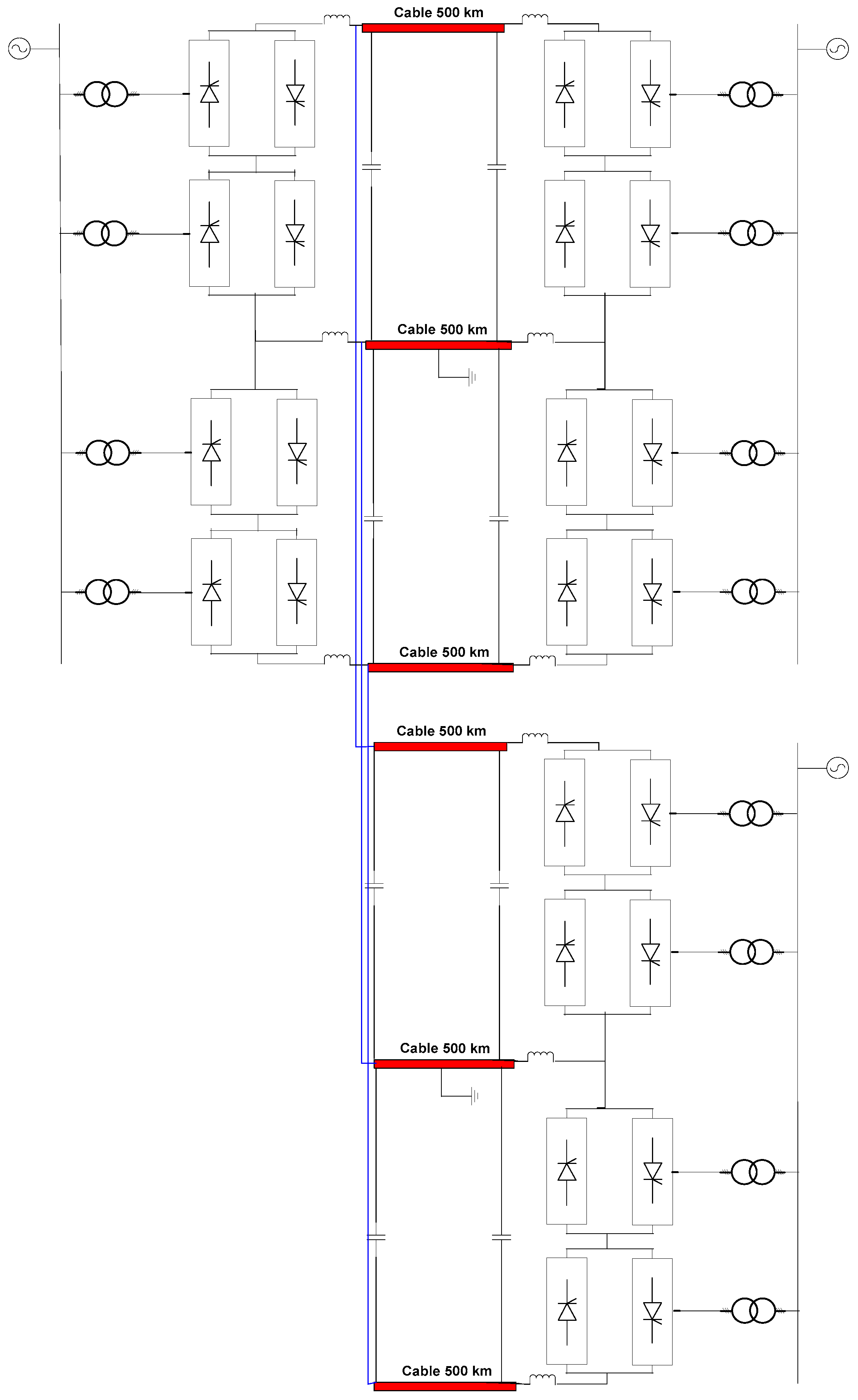
11]. The voltage control is introduced to generate firing angles to the cycloconverters. The current limiter and extinction angle control are included for overcurrent and commutation failure protection of the converters. VSG with a governor control is applied to control the amount of power transmission in the LFAC multi-terminal system application. Furthermore, the proposed control scheme is applied in a two-phase multi-terminal system of LFAC to perform and verify the control operation by PSCAD/EMTDC Software (version 4.2.1, Winnipeg, MB, Canada).

2. Control Strategies for LFAC for the Two-Terminal System

The basic operation of the LFAC transmission system can be described by considering two terminals: sending and receiving ends. A cycloconverter is applied to lower the line frequency from 50/60 Hz to a smaller amount. At the receiving end, another cycloconverter is operated to convert the fraction frequency back to the grid frequency. These two conversions obtain firing angle signals from the designed control scheme, which is achieved by the different phase angles of different terminals. This is one of the common control methods of the LFAC transmitting power control. The active transmitting power over transmission lines can be expressed by Equation (1).
P = V s V R X sin δ
where V S is the sending end voltage, V R is the receiving end voltage, X is line reactance, and δ is the transmitting angle.
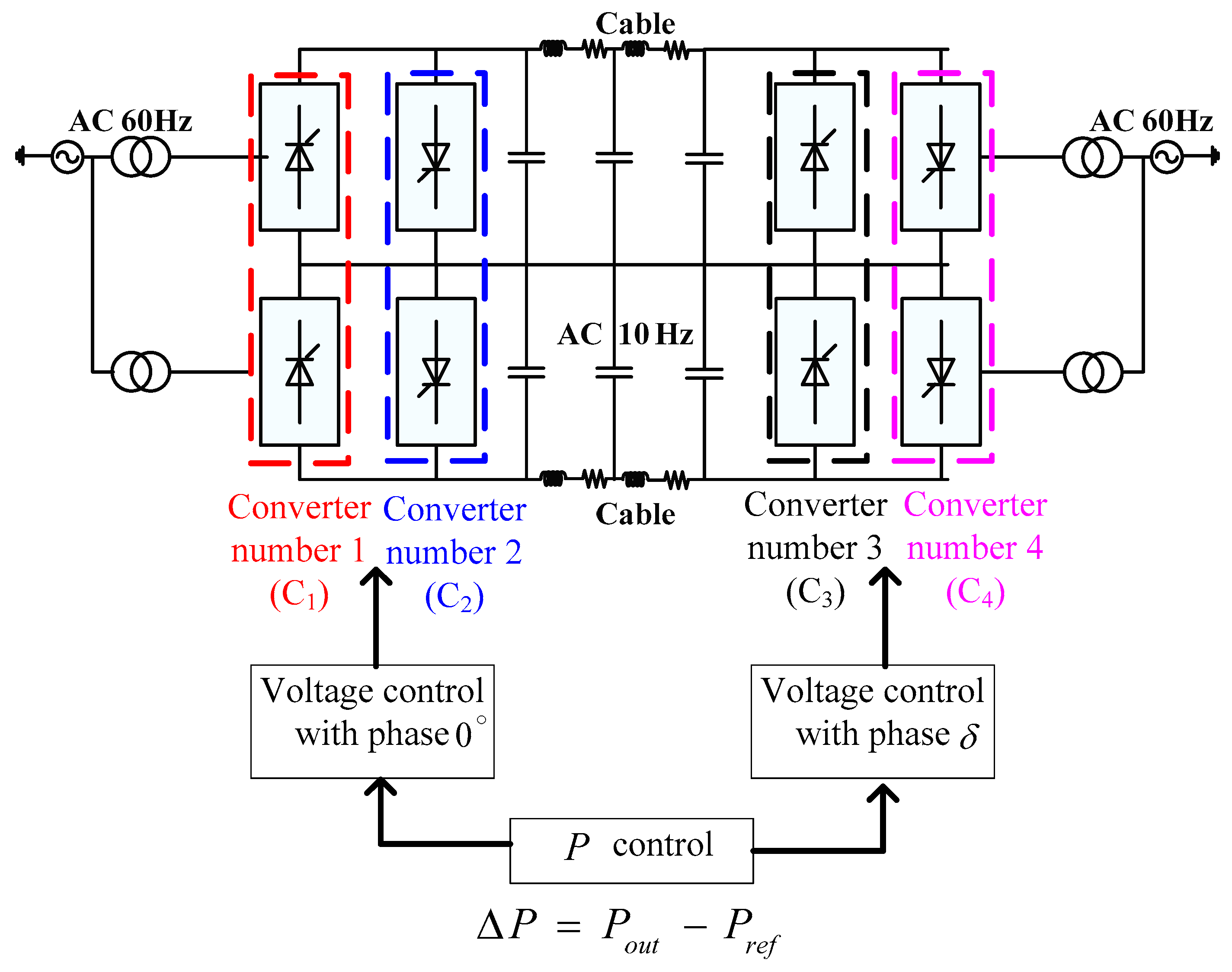
As indicated by Equation (1), the voltage control scheme concept with the LFAC transmission system can be described in Figure 1.
As shown in Figure 1, at the sending end, the phase is set to the constant value of 0° and the amount of transmitting power is determined by the phase difference from the receiving end.
A cycloconverter operates by following the modes in Table 1. On the low frequency side, a positive current waveform can be obtained from converter number 1 and number 4 operations. During the zero crossing point, all converters are blocked by the blocking signal from the controller. The negative current waveform can be received from converter number 3 and number 2 by reversing the current direction.

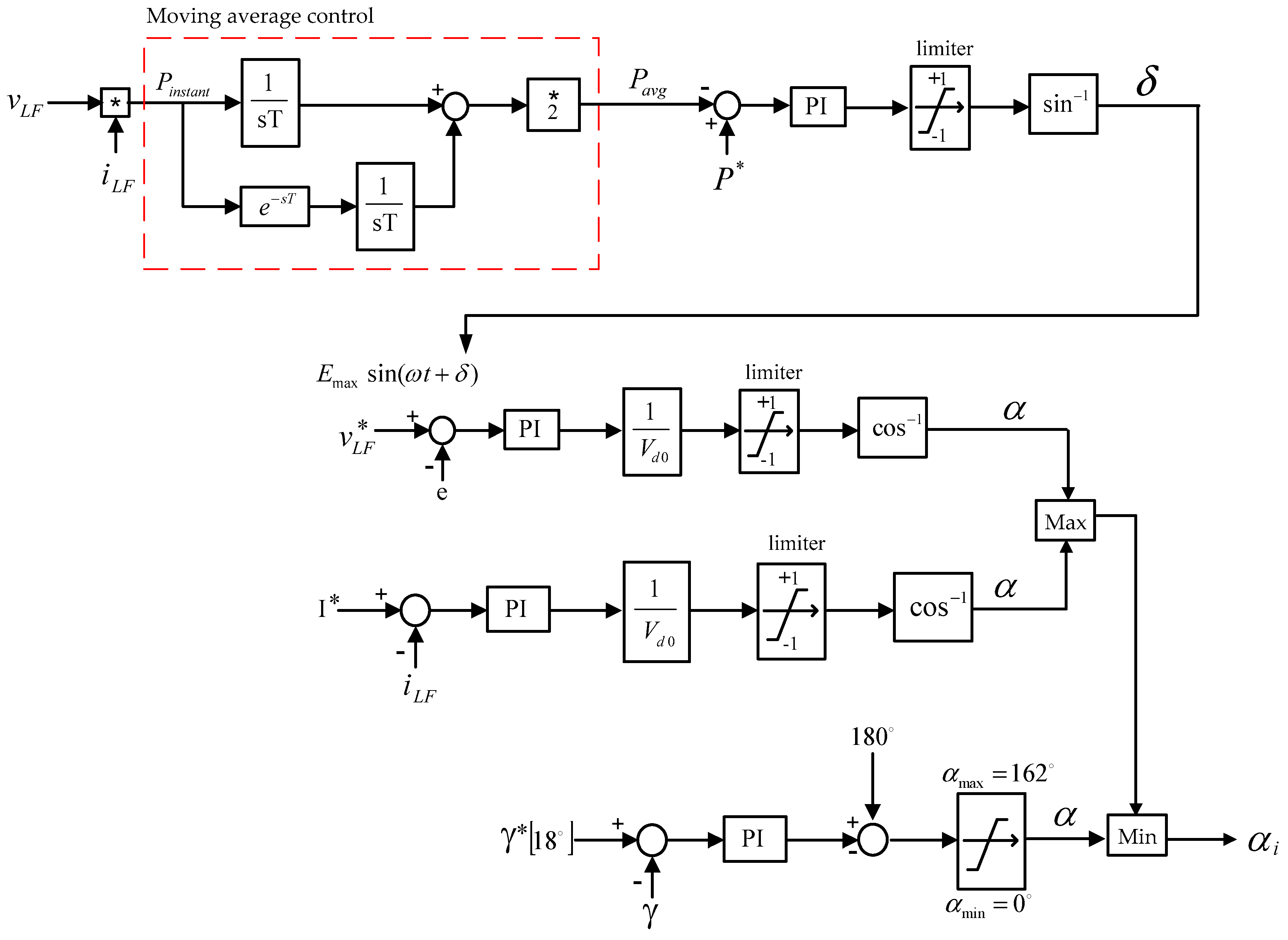
2.1. The Proposed Voltage Control Scheme

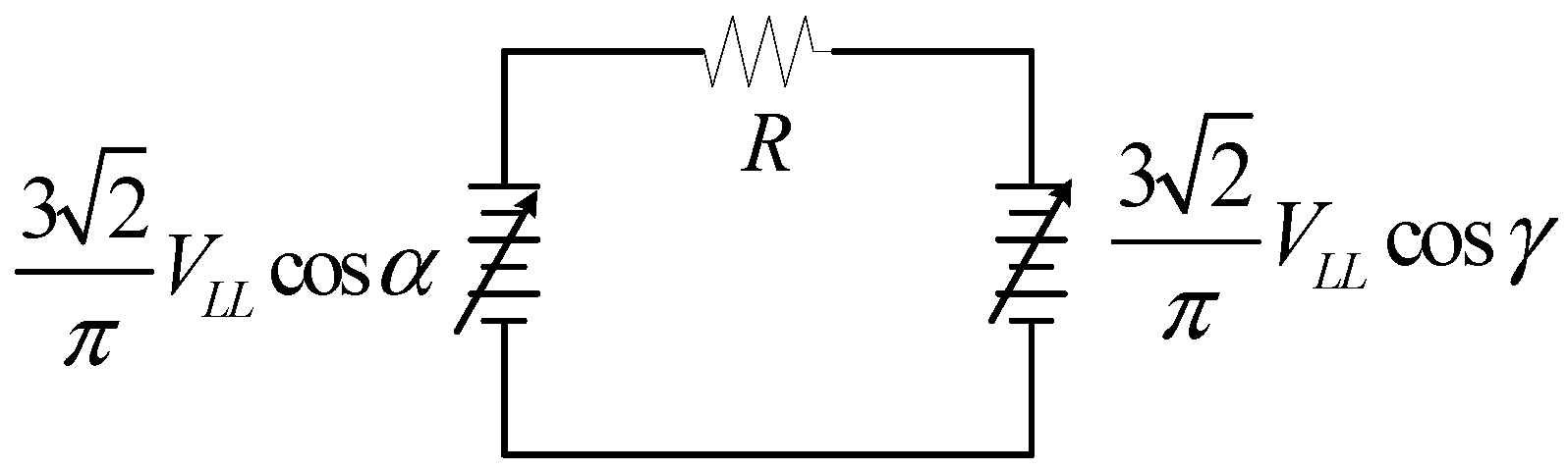
Considering the mode control of the cycloconverter, this converter works as a two-set of HVDC anti-parallel connections and their inputs are a sinusoidal waveform instead of a constant value. From this point of view, the voltage control scheme can be designed by using HVDC concepts, in which the operation is much easier to understand.
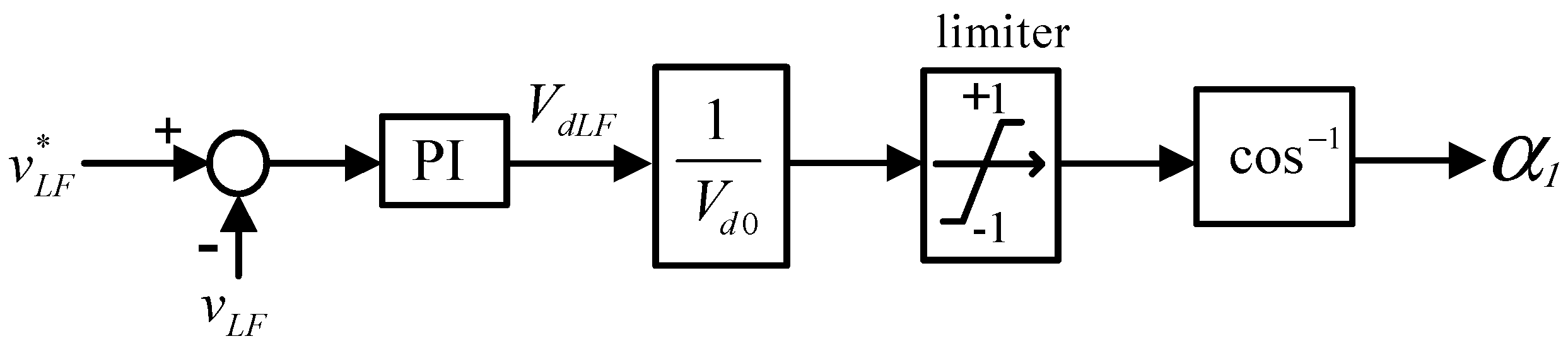
V d = 3 2 π V L L cos α 3 2 π V L L = V d 0 V d = V d 0 cos α
From Figure 2, the Equation (2) is obtained to design the voltage control scheme of the LFAC by substituting V d (DC voltage) with V d L F (voltage on low frequency side) in Figure 3, and V L L is the root mean square (RMS) value of 60 Hz-side AC line to line voltage. The designed control block diagram is shown in Figure 3, in which the voltage reference value of the low frequency side v L F = E m a x sin ( ω t + 0 ° ) is for reference angle side, E m a x sin ( ω t + δ ) is on another side and v L F is the measured instantaneous voltage on low frequency side.
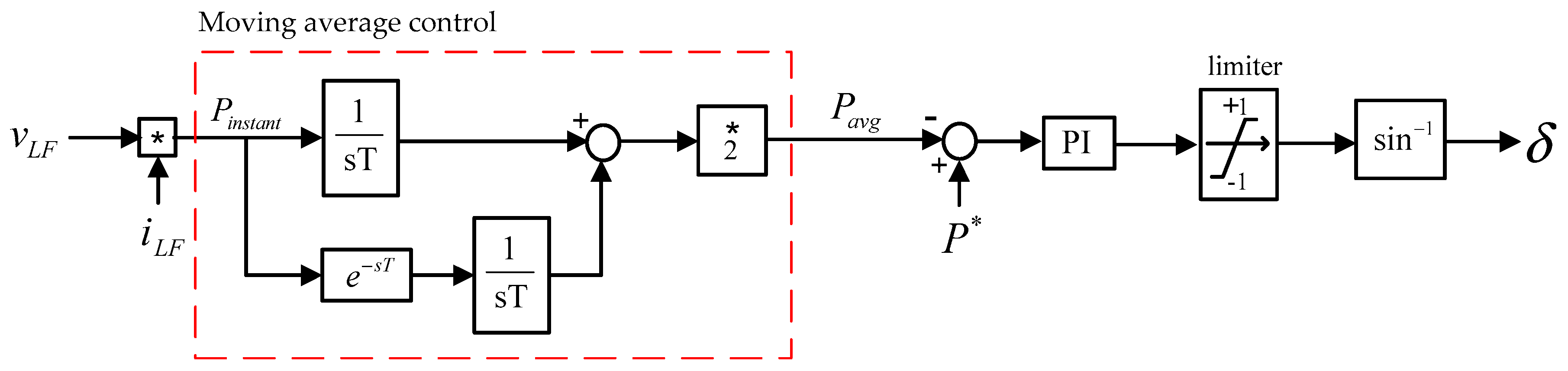
To obtain the phase reference ( δ ), the power control scheme needs to be considered. Equation (1) shows the amount of transmitting power between two terminals following the reference power. Furthermore, power on the low frequency side is not constant, thus the moving average control method is adopted to average the amount of power on the low frequency side. The power control block diagram can be achieved as shown in
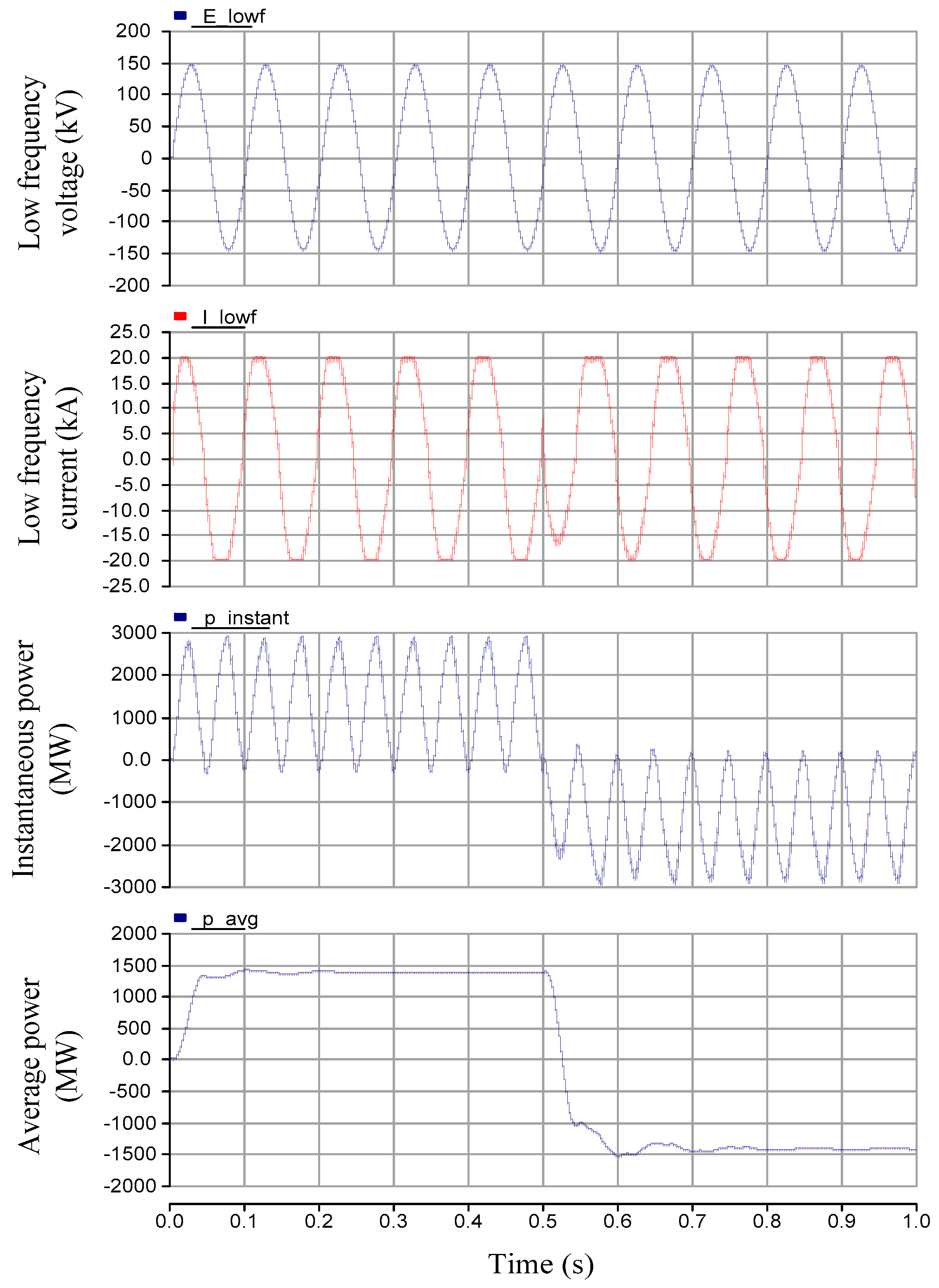
 Figure 4.
To control the amount of transmitting power between each terminal, the power control scheme is chosen for application to the cycloconverters in the LFAC transmission system. According to the system circuit mode and transmitting power in (1), power reference (P*) is compared with average power (Pavg) to obtain the phase difference ( δ ) for the voltage reference.

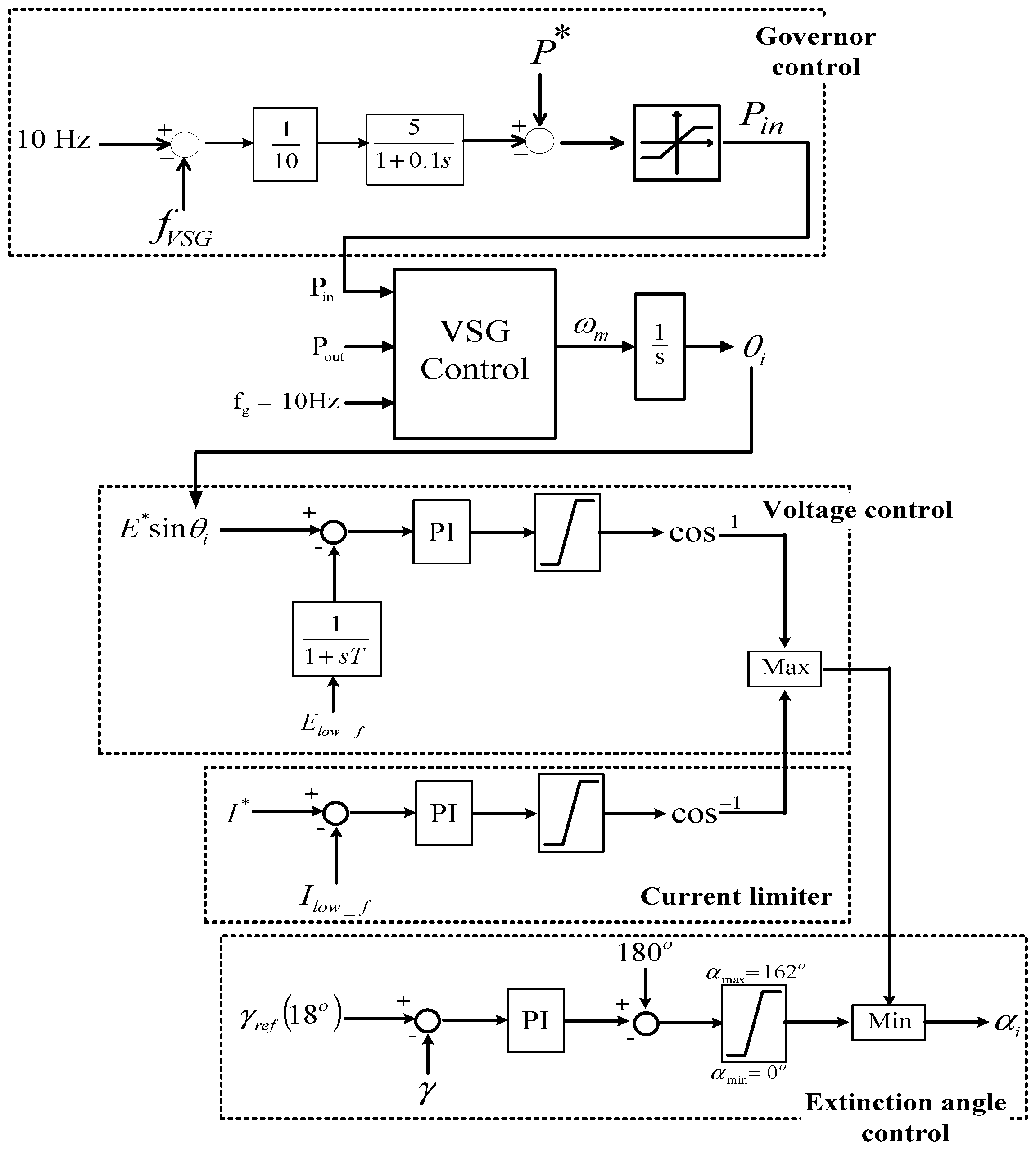
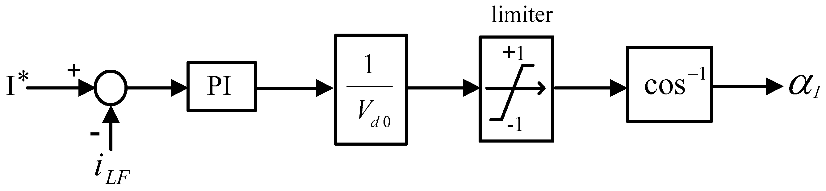
2.2. Proposed Frameworks for Current Limiter and Extinction Angle Control

For protection from overcurrent and commutation failure, a current limiter and extinction angle control are applied in this system. The current limiter is used to limit overcurrent during the transmission of power where i L F = the measured instantaneous current on the low frequency side. The current control scheme is shown in Figure 5.
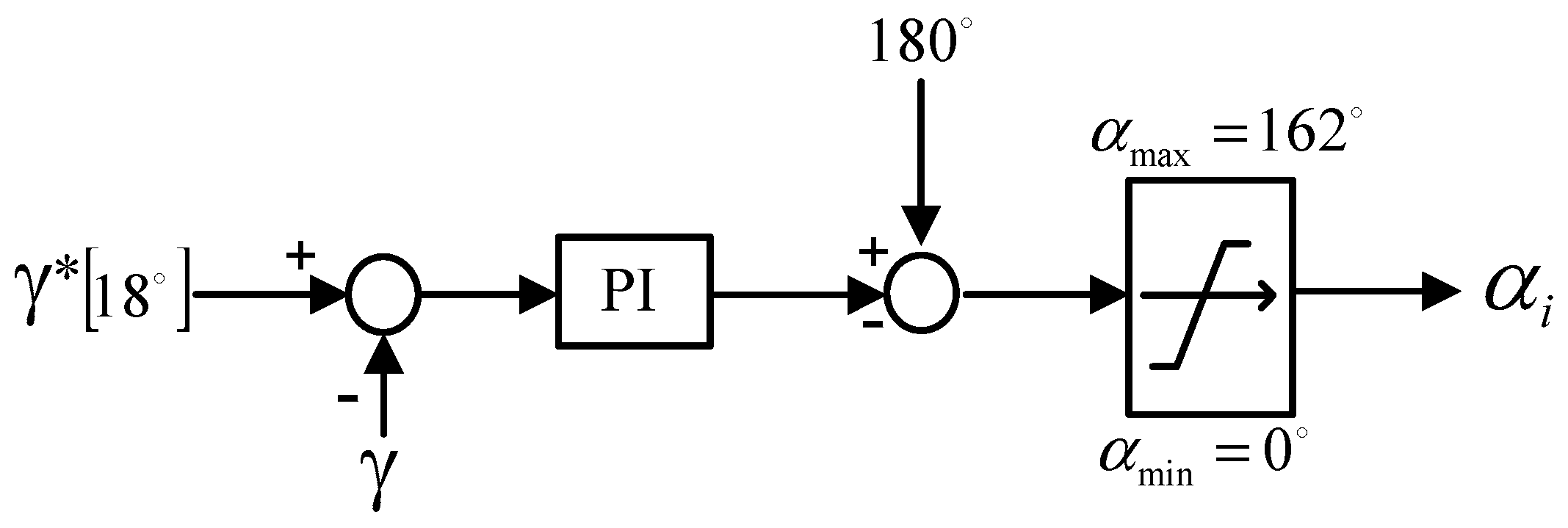
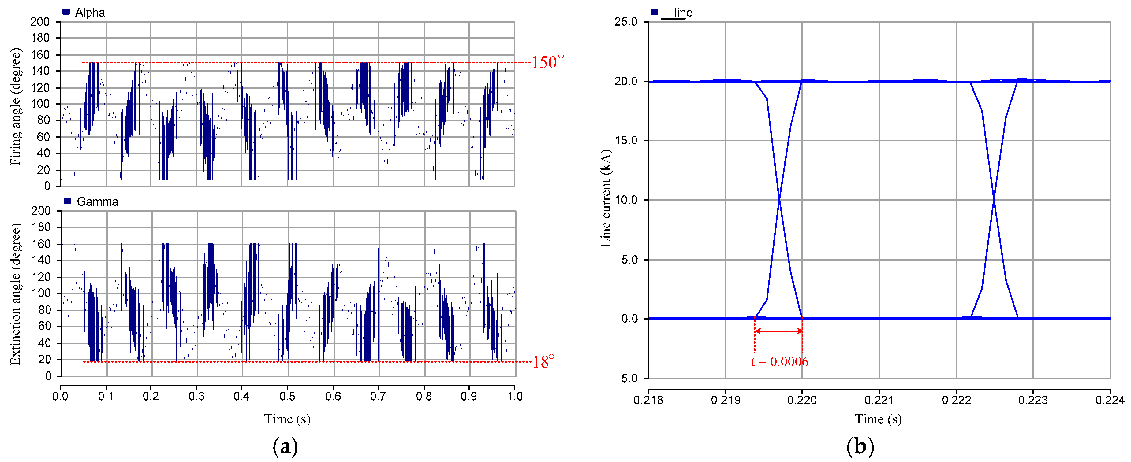
For line-commutated converters, in practice, there are some overlapping angles due to the commutation reactance. The constant extinction angle control (γ) is used to avoid commutation failure. As shown in Figure 6, this extinction angle control works by comparing gamma reference with gamma measure, then the minimum firing angle is chosen to be the gating pulse for cycloconverters. The typical value of extinction angle (γ) is set at 18° for 60 Hz of the AC system.
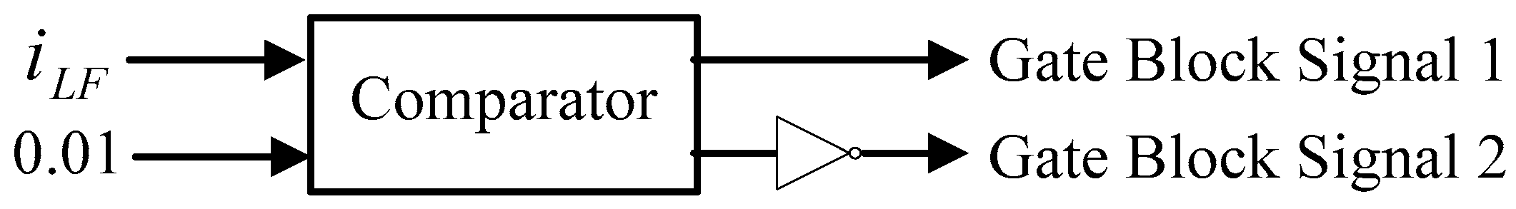
During the zero cross point current, a gate block control scheme is applied to every converter as shown in Figure 7.
In the complete developed control scheme of LFAC, as shown in Figure 8, the same control system is applied for every converter to control the amount of transmitting power between terminals. Following the converter operation mode, δ is set at 0 ° for one side of the converter. On another side of the converter, δ depends on the reference of transmitting power to control the amount and direction.

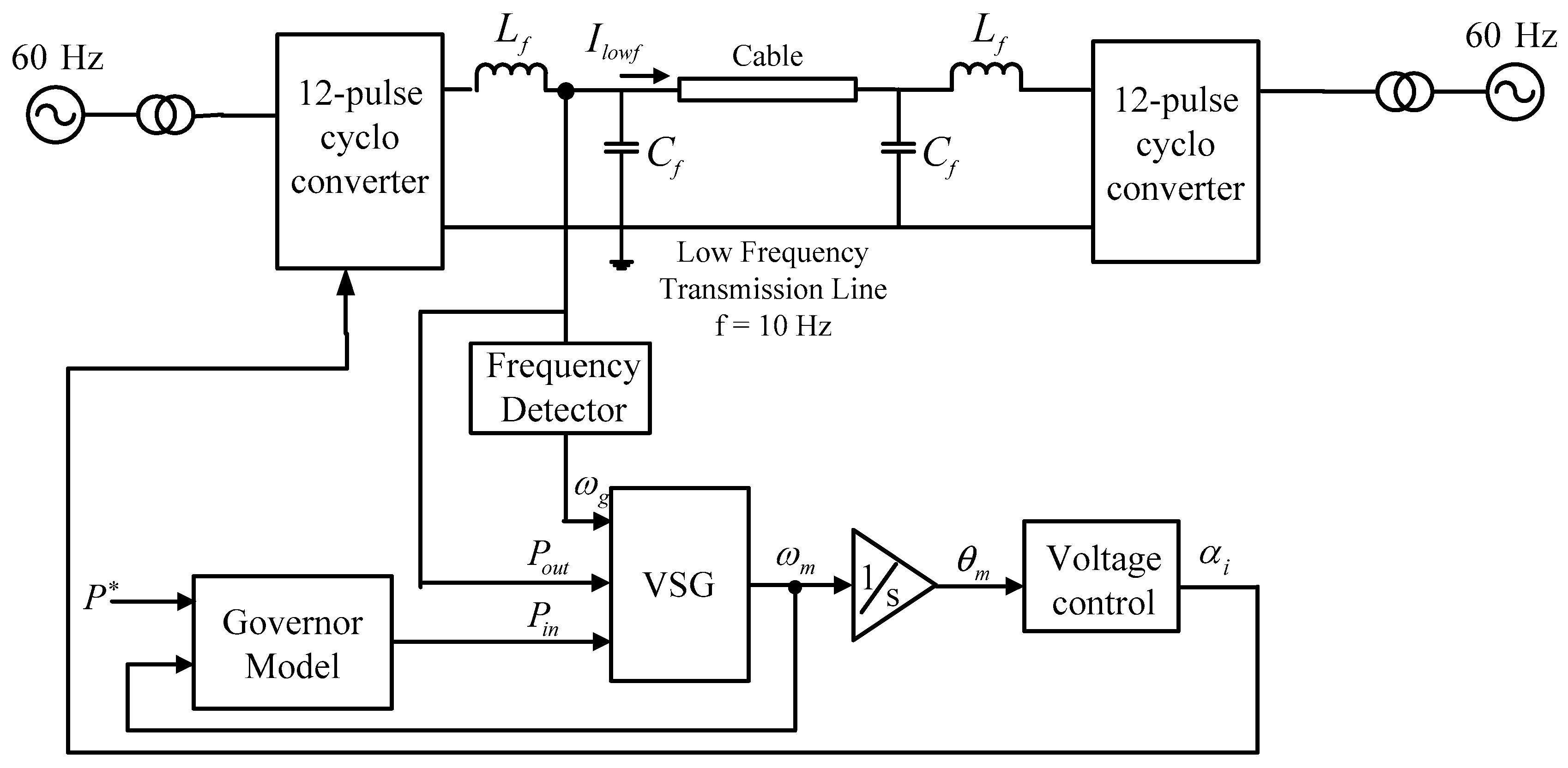
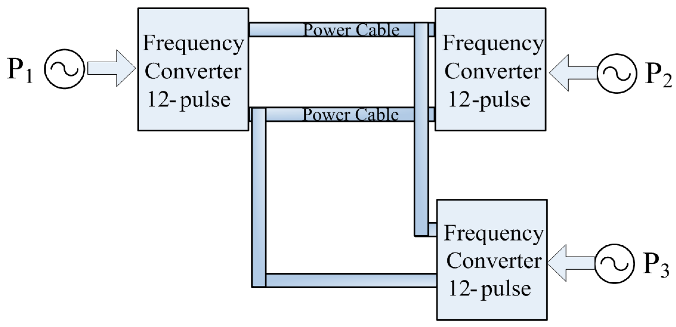
3. Control Strategies for Multi-Terminal LFAC

The proposed control scheme to control the amount of transmitting power and direction among several terminals is explained in this section. In a multi-terminal application of LFAC (LCC-MTLF), a VSG is introduced to synchronize the phase and frequency among terminals instead of a communication link or GPS. The VSG model is based on the swing equation of synchronous generators. Based on this equation, the relation between the output power P o u t and the input power P i n is shown in Equation (3).
P i n P o u t = J ω m d d t ω m + D ( ω m ω g )
where ω m is the virtual rotating angular frequency, ω g is the angular frequency, J is the moment of inertia of rotating mass, and D is the damping factor of the damping power introduced by the damp winding.
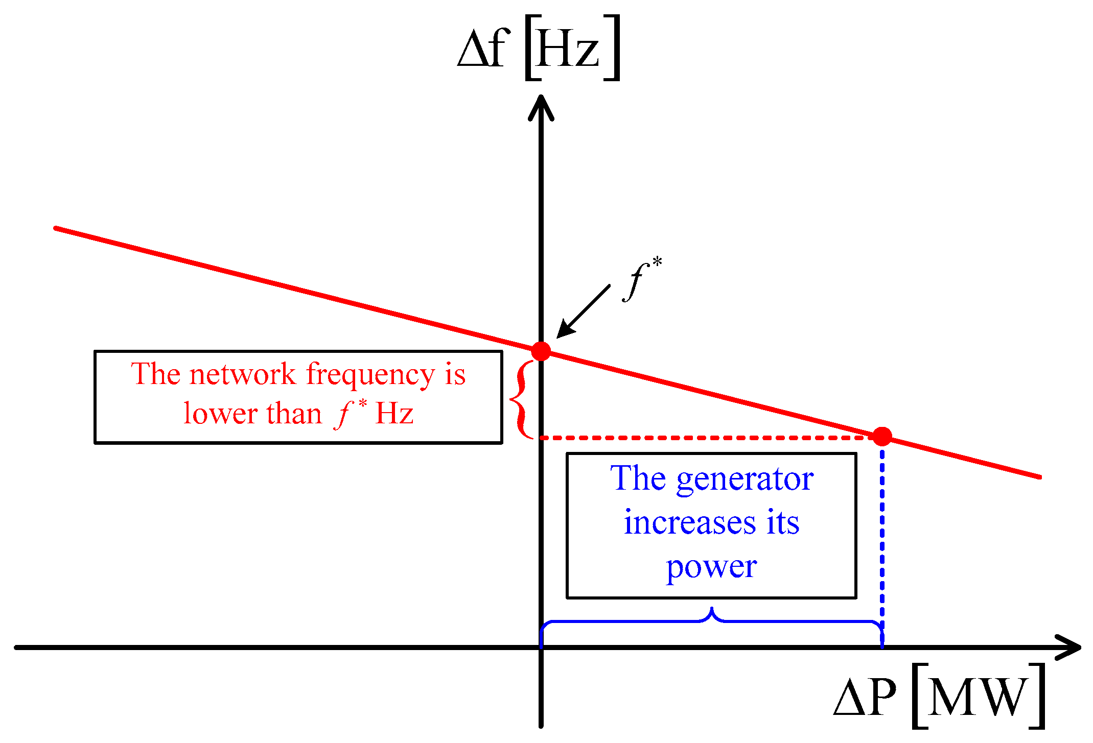
The concept of VSG control is shown in Figure 9. For the power balance between P i n and P o u t , according to the concept of VSG control, if the network frequency is lower than the reference frequency ( f ), then the generator increases its power into the network.
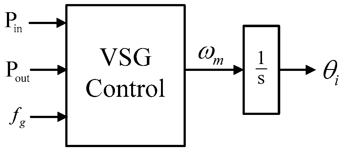
Figure 10 shows the VSG control scheme applied to the LFAC transmission system. The VSG control is emulated to the swing equation in the VSG block.
For simplification, the damping factor 
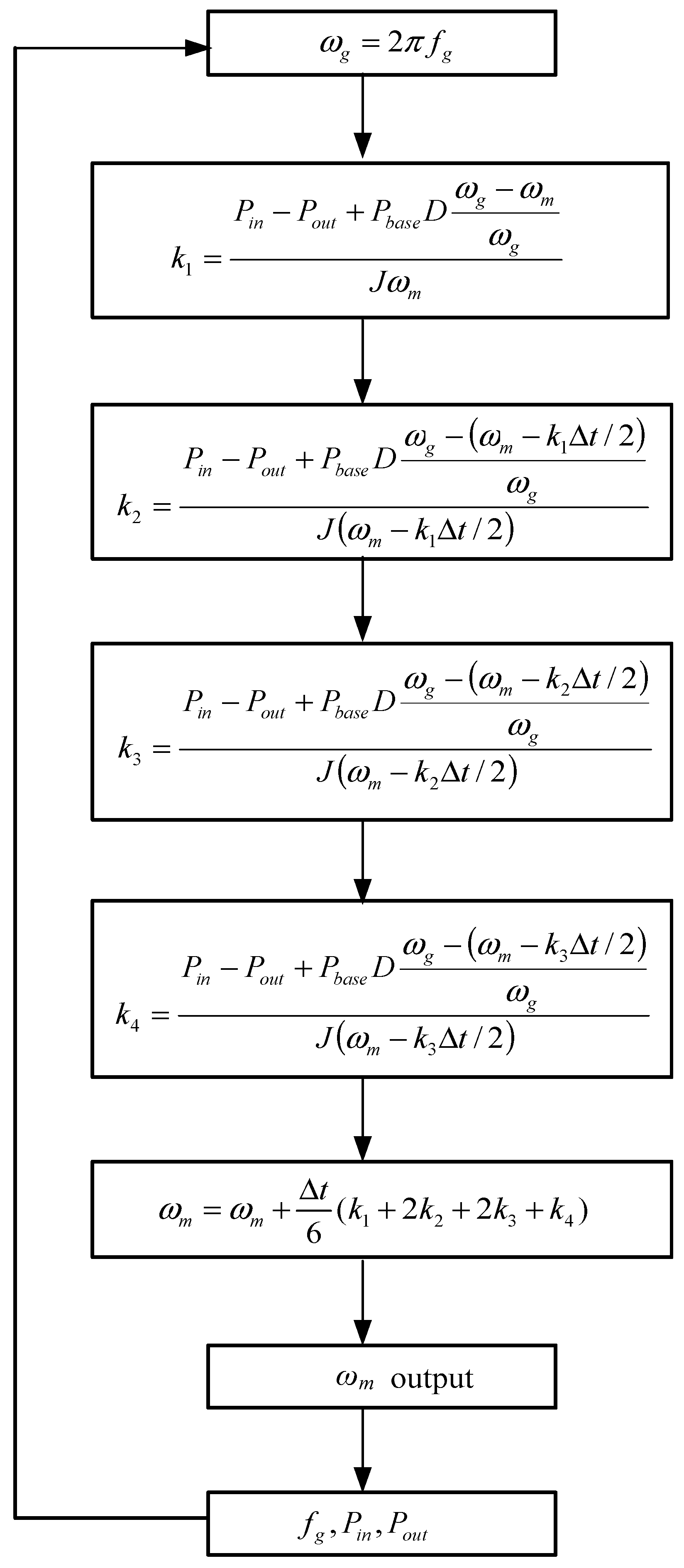
D is considered as a small constant parameter. As the swing equation is a differential equation, an algorithm based on the Runge–Kutta iterative method is used to solve the angular frequency ω m following the flow chart as shown in Figure 11. The calculated ω m provides the frequency reference for the governor model and phase reference θ m through an integrator. Pbase is the rated capacity of transmission power.
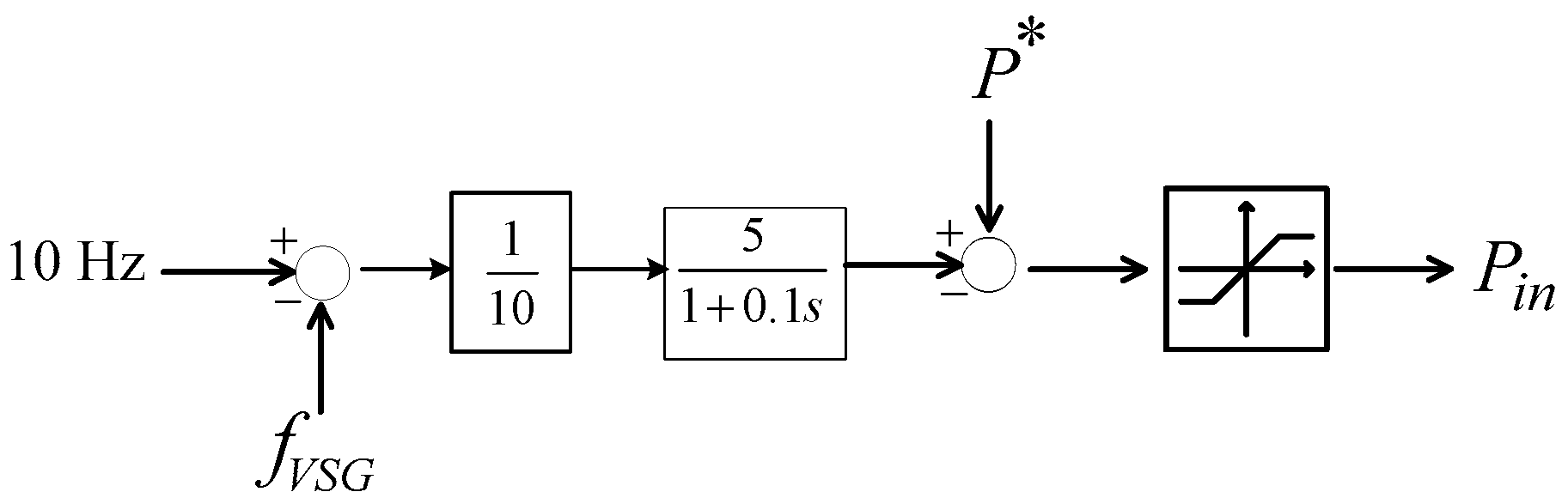
The block of the governor model is shown in Figure 12. The governor model is implemented to tune the input power command based on the frequency deviation. The transfer function of the governor control can be expressed as Equation (4), where Kp = 5, Td = 0.1.
P i n = P + K p 1 + T d s ( f f V S G )
In the VSG control part as shown in Figure 13, Pin, Pout and low frequency side frequency ( f g ) are inputs of the VSG control unit. In each control cycle, the momentary ω m is calculated via the application of the fourth-order Runge–Kutta iterative method inside the VSG block to generate the virtual phase angle θ i (i = 1, 2, 3) sent through the voltage control unit.
As for the voltage control scheme, the concept of the control operation is the same as the voltage control scheme as described in Section 2.1. When a disturbance occurs, or more load shares are added to the system, the system can stabilize itself by regulating voltage using this control.
The current limiter works by comparing the rating current with measured current from the low frequency side to generate the firing angle to the cycloconverter, which can limit overcurrent by limiting the firing angle to the cycloconverter. Also, extinction angle control (γ) is included to avoid commutation failure in a converter.
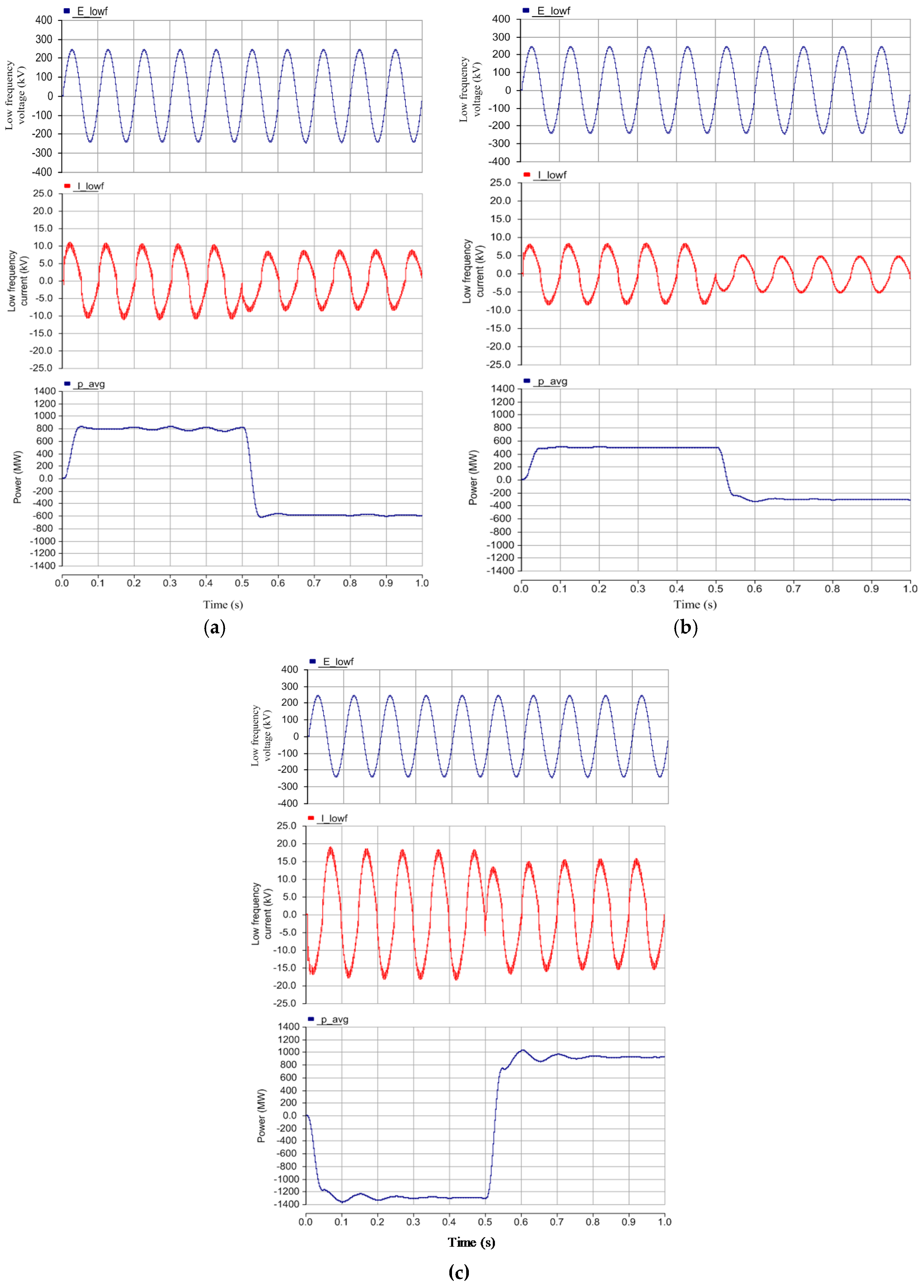
By combining each part of the control scheme, the complete control scheme of the multi-terminal LFAC transmission system is shown in Figure 14. The voltage control receives the virtual phase angle θ i from the VSG block to be the voltage reference, then the firing angle α i is generated and is sent to the cycloconverters.

4. Simulation Results

To demonstrate the validity of the proposed power control scheme for the multi-terminal LFAC application, the simulations have been carried out using the tool of the PSCAD/EMTDC simulation software. The transmitting power in this system is rated at 1400 MW, and the transmission distance is 500 km. The transmission power cable is modeled by cascading 10 km of cable; its model is shown in Figure 15.
For the simulation of the multi-terminal LFAC application, a three-terminal two-phase LFAC configuration [1] is applied with a proposed power control scheme as shown in Figure 16.

4.1. Current Limiter and Extinction Angle Control Operation

From the proposed control scheme in Section 2.2, some simulation results are performed to verify the control operation. Figure 17 shows the simulation result of the extinction angle control that cannot exceed the limit at the reference γ = 18 ° . An extinction angle γ is calculated from the equation γ = 180 ° ( α + u ) where u = 12 ° as shown in Figure 17b. The overlapping angle is around 12 ° for 60 Hz and γ is controlled at 18 ° . This can confirm the extinction angle control scheme works well.
During the period of transition, the mode of the cycloconverter may cause a spike current. This can malfunction with devices in the system so that the current limiter is used for protection. From the control scheme shown in Figure 5, the current limiter works by comparing the rating current with the measure current from the low frequency side to generate the firing angle to the cycloconverter. The current limiter can limit the overcurrent by limiting the firing angle to the cycloconverter. Figure 18 shows the result of the current limiter control that limits current at 20 kA on the low frequency side. The E_lowf waveform is transmitting low frequency AC voltage, following the reference value from the control scheme. The I_lowf waveform shows a transmitting current on the low frequency side, which is limited at 20 kA due to the current limiter. From the result, it can be confirmed that the current limiter control can work properly.

4.2. Multi-Terminal LFAC Response

The simulation results of the three-terminal two-phase LFAC system are explained in this section. In the performed multi-terminal configuration, as mentioned in Figure 16, the multi-terminal LFAC demonstrates the effectiveness of the proposed system and control method. The total amount of power in this system is 1400 MW. The power flow pattern is shown Figure 19 and the details are shown in Table 2. In the power flow schedule given in Table 2, terminals 1, 2 and 3 are desired to inject a power of 800 MW, 500 MW and −1300 MW into the grid. The minus signs show that the power flow is in the opposite direction. The simulation parameters are shown in Table 3.
Figure 20 depicts the results of a simulation where the transmitting power flows from terminals 1 at 800 MW, and 2 and 3 at 500 MW and 1300 MW, respectively. After 0.5 s, the power direction is reversed following power references (terminal 1 at 600 MW, terminal 2 at 300 MW and terminal 3 at 900 MW). The voltage (E_lowf), current (I_lowf), and average power (p_avg) are the results on the low frequency side. As can be seen from the simulation results, the amount of power in each terminal can be transferred following the power flow patterns given in Table 2. The transmitting power on the low frequency side is 10 Hz following the reference. Figure 19 shows the power that flows from terminal 1 at 800 MW and in the reverse direction at 0.5 s following the power control scheme command.
Figure 20b,c shows the result of the power transmission at terminals 2 and 3. The results show that the amount and direction of power can follow the power flow patterns. It can be confirmed that the proposed power control for the multi-terminal LFAC using the VSG control works properly.

5. Conclusions

This paper explains the proposed power control scheme of the multi-terminal LFAC application. A three-terminal two-phase LFAC cycloconverter configuration is applied to operate with the proposed control scheme. There are three main important points to be concluded as follows:
(1)
The proposed power control scheme which was explained in detail is feasible for synchronized frequency and regulated voltage by integrating VSG and the governor control to the control scheme;
(2)
A two-phase LFAC configuration was adopted to operate as a multi-terminal system LFAC. The simulation results confirm the operation of the current limiter and extinction angle control, which operated using this configuration;
(3)
The multi-terminal LFAC application was operated by using the proposed power control scheme to transmit power among three terminals following the reference power patterns. The simulation results verified the operation of the proposed control scheme with the given transmission system without a communication link.
This study can lead us to consider more details such as adding additional terminals to operate with the proposed control scheme and configuration. Comparing merits and drawbacks of the system with other existing multi-terminal transmission systems in the presence of various disturbance scenarios could be considered as the future steps for the present work.

Author Contributions

Achara Pichetjamroen conceived the proposed control strategy, performed calculation, simulation of the system and wrote the paper. Toshifumi Ise as research supervisor provided guidance and key suggestions, participated in proposing the ideas of the system configurations and control scheme, and helped in writing the paper.

Conflicts of Interest

The authors declare no conflict of interest.

References

  1. Achara, P.; Ise, T. A proposal on low frequency AC transmission as a multi-terminal transmission system. Energies 2016, 9, 687. [Google Scholar]
  2. Bozhko, S.; Asher, G.; Li, R.; Clare, J.; Yao, L. Large offshore DFIG based wind farm with line-commutated HVDC connection to the main grid: Engineering studies. IEEE Trans. Energy Convers. 2008, 23, 119–127. [Google Scholar] [CrossRef]
  3. Mau, C.N.; Rudion, K.; Orths, A.; Eriksen, P.B.; Abildgaard, H.; Styczynski, Z.A. Grid connection of offshore wind farm based DFIG with low frequency AC transmission system. In Proceedings of the Power and Energy Society General Meeting, San Diego, CA, USA, 22–26 July 2012.
  4. Tuan, N.; Min, L.; Surya, S. Steady-state analysis and performance of low frequency AC transmission lines. IEEE Trans. Power Syst. 2016, 31, 3873–3880. [Google Scholar]
  5. Slade, P.G.; Smith, R.K. A comparison of the short circuit interruption performance using transverse magnetic field contacts and axial magnetic field contacts in low frequency circuits with long arcing times. In Proceedings of the Discharges and Electrical Insulation in Vacuum International Symposium, Yalta, Crimea, 27 September–1 October 2004.
  6. Etienne, V.; Boon, T.O. Multiterminal HVDC with thyristor power-flow controller. IEEE Trans. Power Deliv. 2012, 27, 1205–1212. [Google Scholar]
  7. Funaki, T.; Matsuura, K. Feasibility of the low frequency AC transmission. In Proceedings of the Power Engineering Society Winter Meeting, Singapore, 23–27 January 2000.
  8. Cho, Y.; Cokkinides, G.J.; Meliopoulos, A.P. Time domain simulation of a three-phase cycloconverter for LFAC transmission systems. In Proceedings of the Transmission and Distribution Conference and Exposition, Orlando, FL, USA, 7–10 May 2012.
  9. Nakagawa, R.; Funaki, T.; Matsuura, K. Installation and control of cycloconverter to low frequency AC power cable transmission. In Proceedings of the Power Conversion Conference, Osaka, Japan, 2–5 April 2002.
  10. Chen, H.; Johnson, M.H.; Aliprantis, D.C. Low frequency AC transmission for offshore wind power. IEEE Trans. Power Deliv. 2013, 28, 2236–2244. [Google Scholar] [CrossRef]
  11. Bevrani, H.; Ise, T.; Miura, Y. Virtual synchronous generators: A survey and new perspectives. Int. J. Electr. Power Energy Syst. 2014, 54, 244–254. [Google Scholar] [CrossRef]
Figure 1. Concept of low frequency AC transmission system (LFAC) control scheme.
Energies 10 00034 g001
Figure 2. Equivalent circuit of High Voltage Direct Current (HVDC) link.
Energies 10 00034 g002
Figure 3. Voltage control of LFAC.
Energies 10 00034 g003
Figure 4. Power control of LFAC.
Energies 10 00034 g004
Figure 5. Current limiter of LFAC.
Energies 10 00034 g005
Figure 6. Extinction angle control of LFAC.
Energies 10 00034 g006
Figure 7. Gate block control scheme of LFAC.
Energies 10 00034 g007
Figure 8. The proposed overall control scheme of LFAC.
Energies 10 00034 g008
Figure 9. Concept of virtual synchronous generator (VSG) control.
Energies 10 00034 g009
Figure 10. Block diagram of the VSG control scheme for LFAC.
Energies 10 00034 g010
Figure 11. Flow chart of solving swing equation by Runge–Kutta method.
Energies 10 00034 g011
Figure 12. Governor control scheme.
Energies 10 00034 g012
Figure 13. VSG control scheme.
Energies 10 00034 g013
Figure 14. Complete control scheme of multi-terminal LFAC.
Energies 10 00034 g014
Figure 15. Cable model for the simulation.
Energies 10 00034 g015
Figure 16. Three-terminal two-phase LFAC.
Energies 10 00034 g016
Figure 17. Simulation result of extinction control. (a) Firing angle and extinction angle during operation at 20 kA; and (b) line current waveforms.
Energies 10 00034 g017
Figure 18. Simulation result for current limiter control.
Energies 10 00034 g018
Figure 19. Power flow patterns for simulation.
Energies 10 00034 g019
Figure 20. Low frequency side waveforms (voltage, current and power) on (a) terminal 1; (b) terminal 2; and (c) terminal 3.
Energies 10 00034 g020
Table 1. Mode operation of the cycloconverter.
Operating ConverterPositive CurrentZero Cross PointNegative Current
Rectifier No. of operating converterC1BlockC3
Inverter No. of operating converterC4BlockC2
Table 2. Power flow patterns.
Terminal No.P* (Power Reference, MW)
SendingReceiving
1800−600
2500−300
3−1300900
Table 3. Parameters of simulated system.
LFAC System500 kV, 10 Hz
Line frequency60 Hz
Transmitting frequency10 Hz
Transformer500 kV/110 kV
Maximum power transfer1400 MW
Maximum cable length500 km
Number of terminals3
Power reversalAfter 0.5 s

