
Experimental Study on Specific Heat of Concrete at High Temperatures and Its Influence on Thermal Energy Storage

Abstract
:1. Introduction
2. Test Method and Material
2.1. Specific Heat Test Method
2.1.1. Half-Open Dynamic Method Based on Mixing Principle
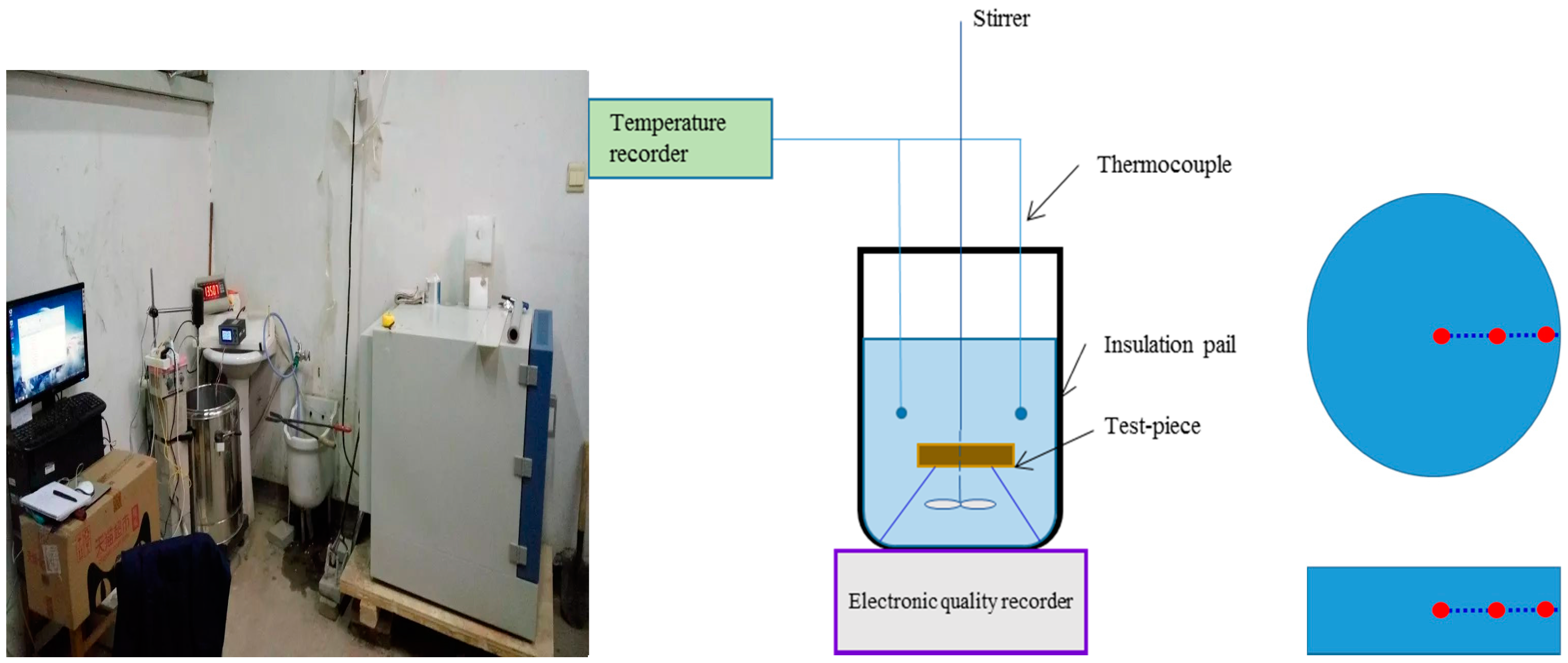
2.1.2. Test Device and Test Procedure
2.1.3. Formula Derivation
2.2. Test Materials
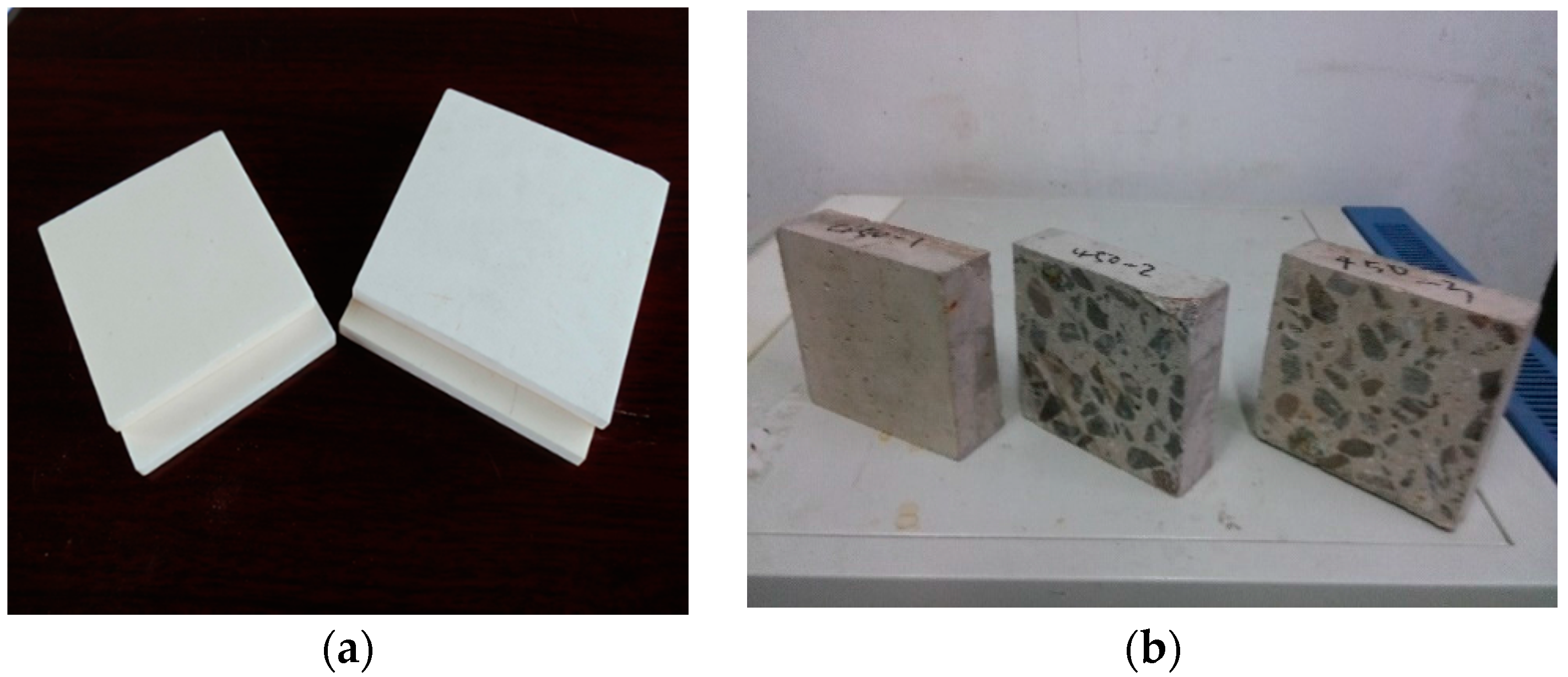
2.2.1. Corundum Blocks
2.2.2. Concrete Material
3. Test Results
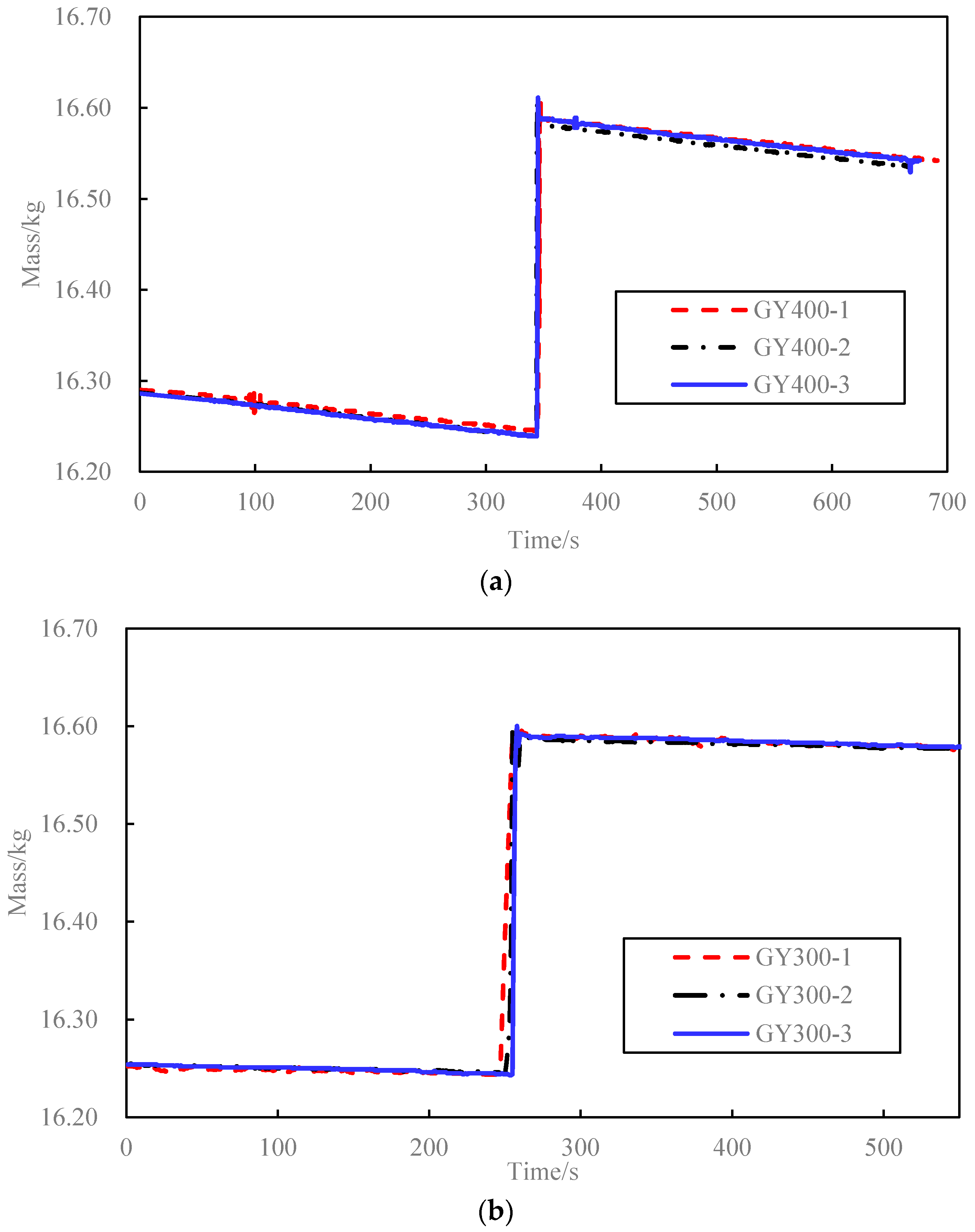
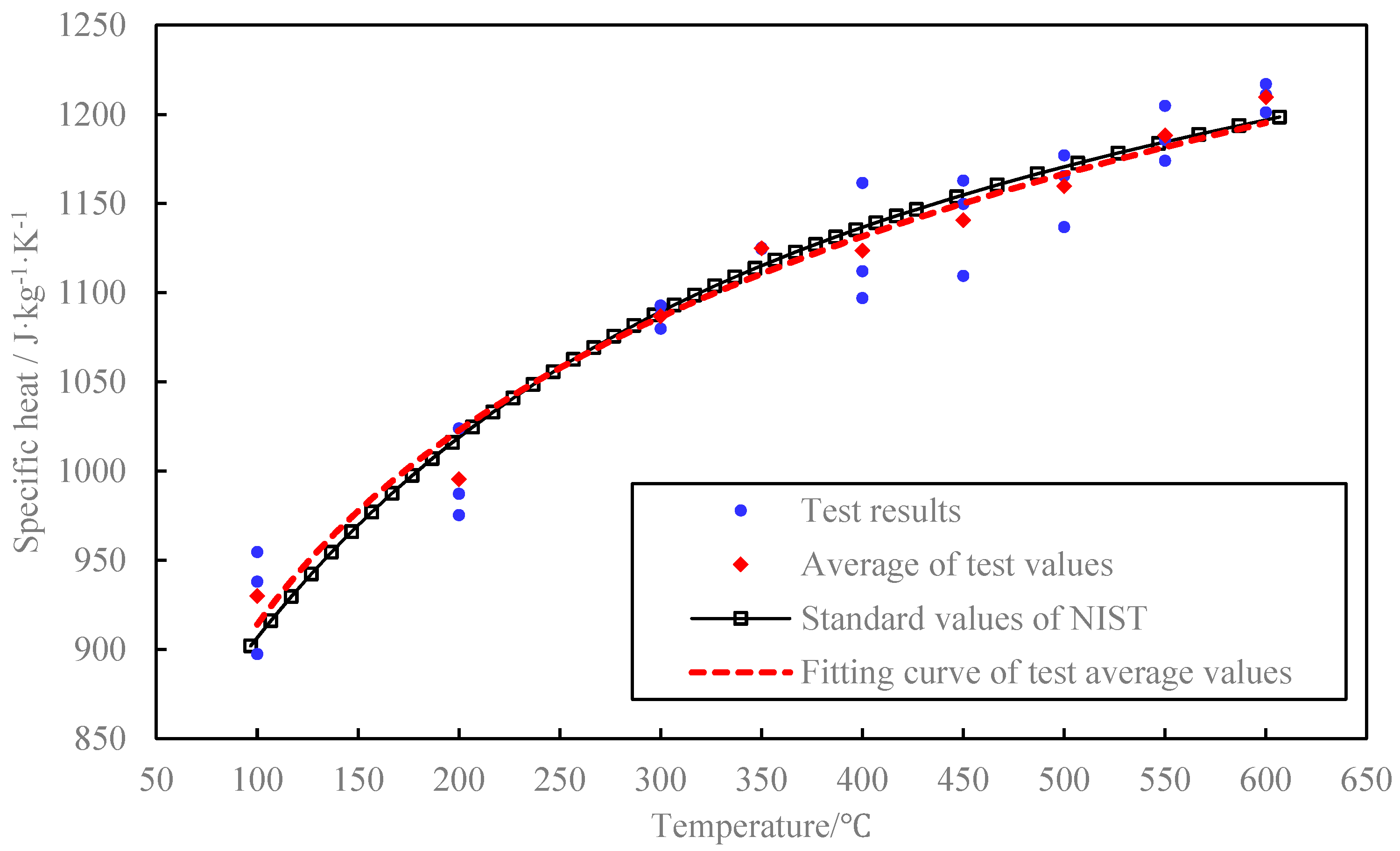
3.1. Corundum Blocks Test Result
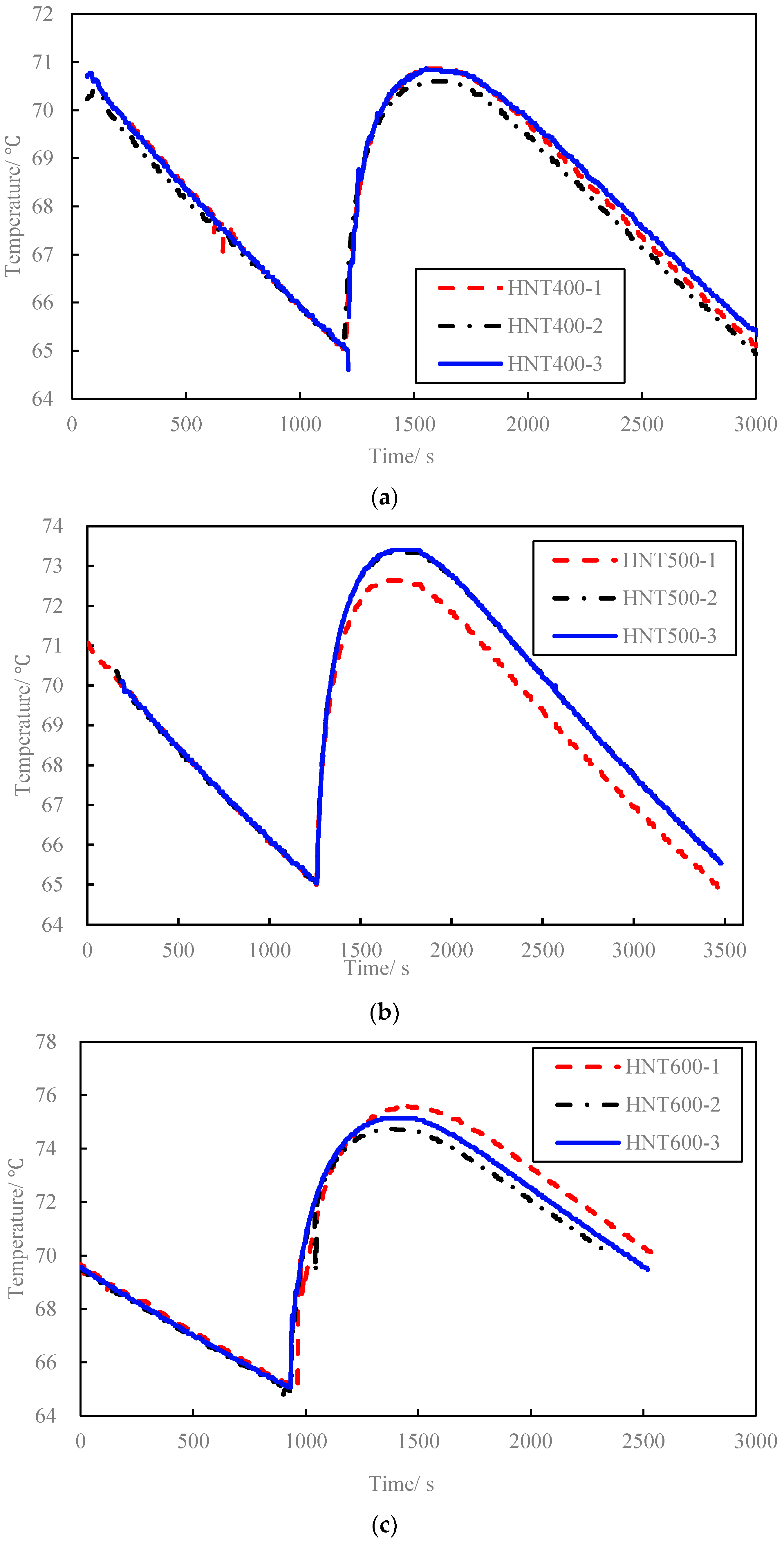
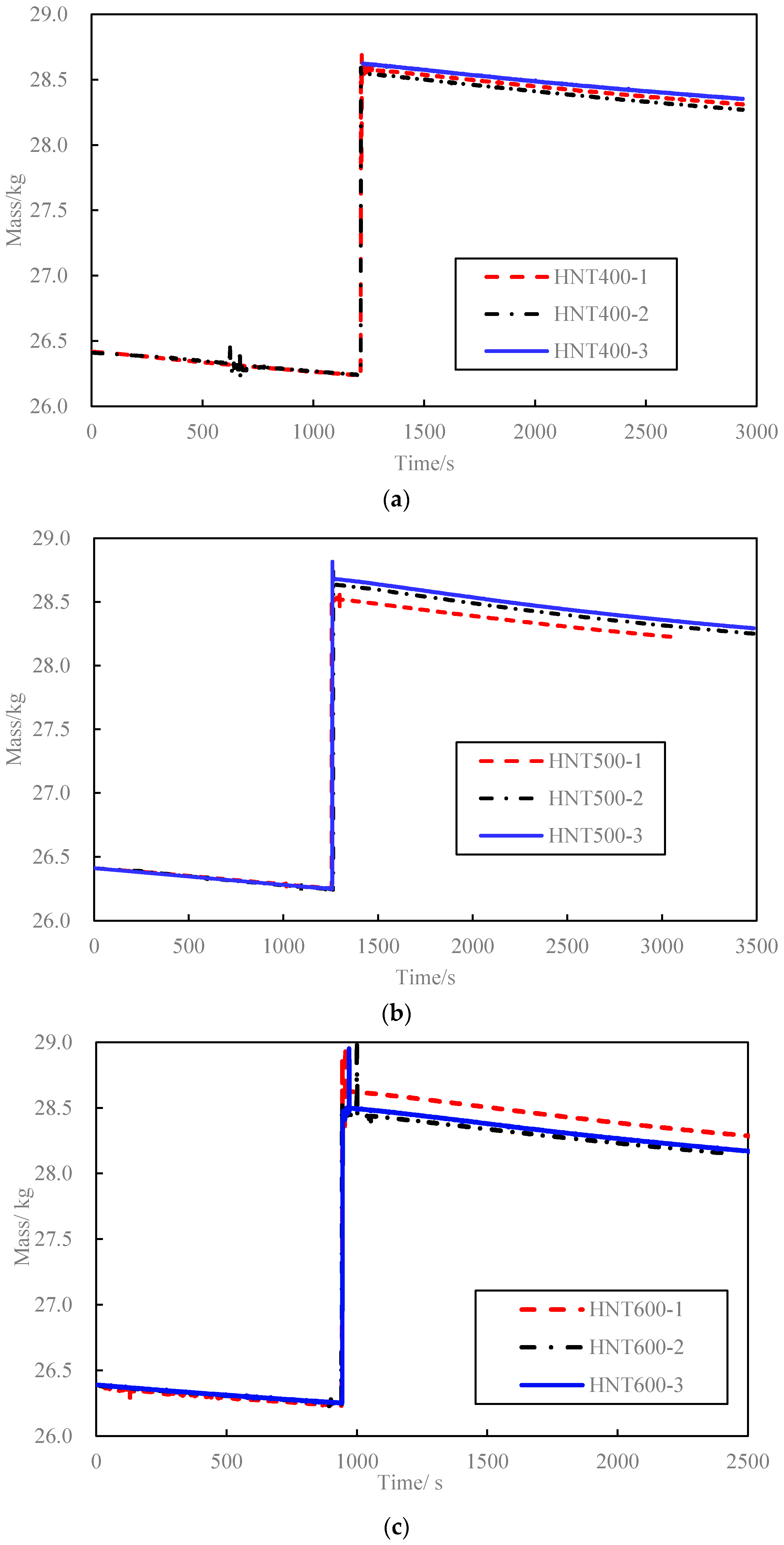
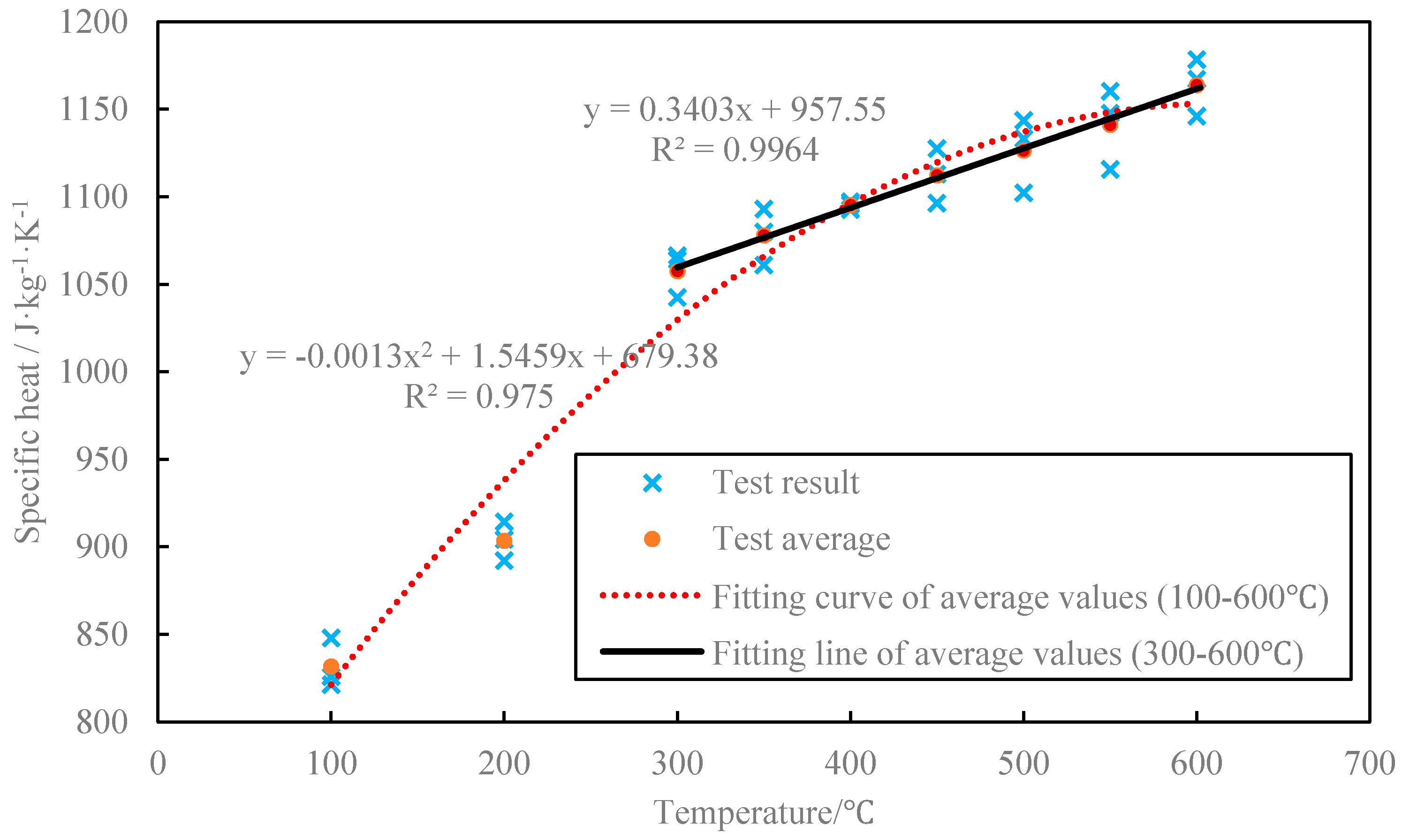
3.2. Concrete Blocks Test Result
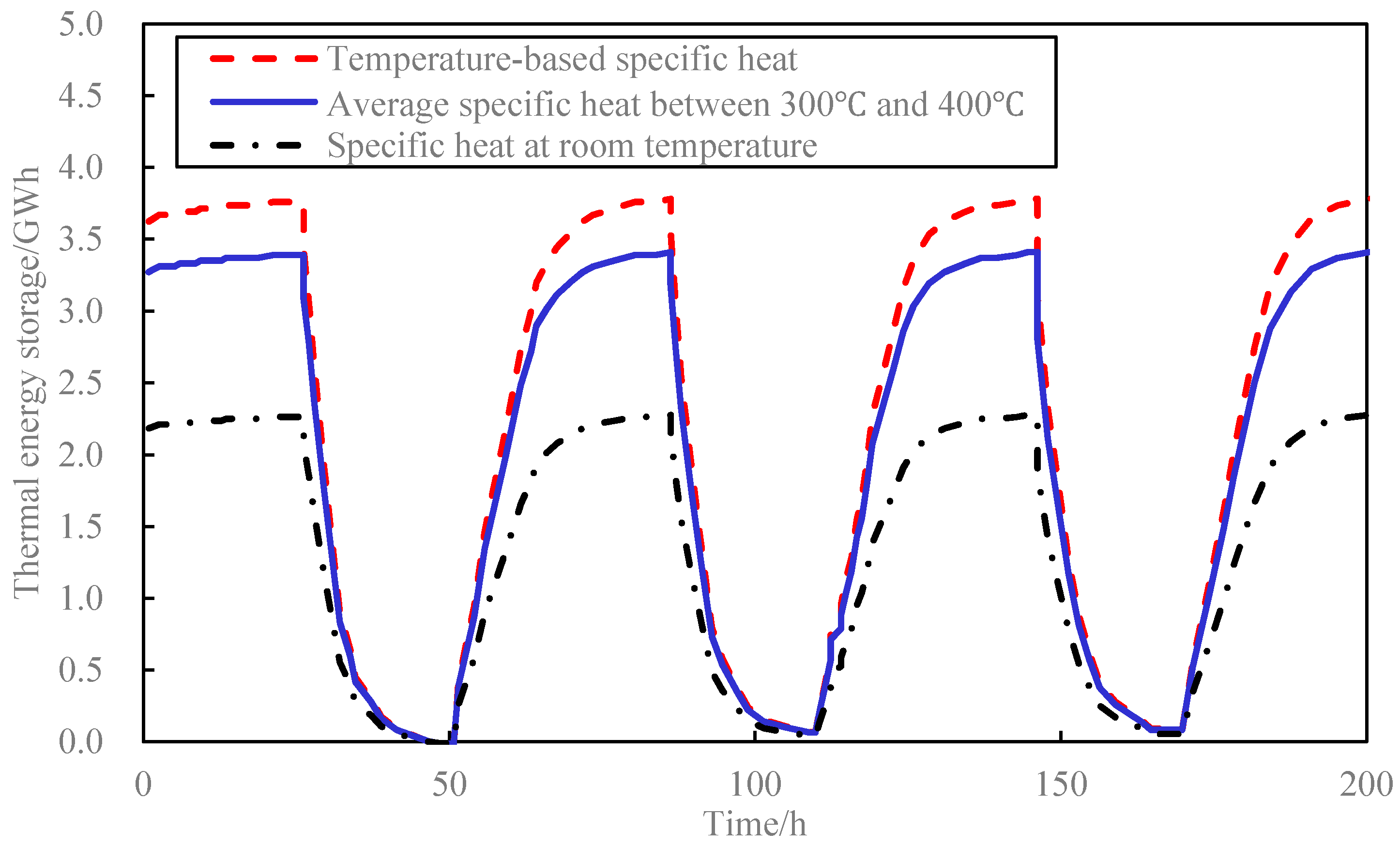
4. Influence of Concrete Specific Heat on TES Capacity
5. Conclusions
Acknowledgments
Author Contributions
Conflicts of Interest
References
- Laing, D.; Steinmann, W.; Tamme, R.; Richterb, C. Solid media thermal storage for parabolic trough power plants. Sol. Energy 2006, 80, 1283–1289. [Google Scholar] [CrossRef]
- Laing, D.; Steinmann, W.D.; Fiss, M.; Tamme, R.; Brand, T.; Bahl, C. Solid media thermal storage development and analysis of modular storage operation concepts for parabolic trough power plants. J. Sol. Energy Eng. 2008, 130, 1–5. [Google Scholar] [CrossRef]
- Laing, D.; Lehmann, D.; Fiss, M.; Bahl, C. Test Results of Concrete Thermal Energy Storage for Parabolic Trough Power Plants. J. Sol. Energy Eng.-Trans. ASME 2009, 131, 0410074. [Google Scholar] [CrossRef]
- Laing, D.; Bahl, C.; Bauer, T.; Fiss, M.; Breidenbach, N.; Hempel, M. High-Temperature Solid-Media Thermal Energy Storage for Solar Thermal Power Plants. Proc. IEEE 2012, 100, 516–524. [Google Scholar] [CrossRef]
- Gil, A.; Medrano, M.; Martorell, I.; Lázaro, A.; Dolado, P.; Zalba, B.; Cabeza, L.F. State of the art on high temperature thermal energy storage for power generation. Part 1—Concepts, materials and modellization. Renew. Sustain. Energy Rev. 2010, 14, 31–55. [Google Scholar] [CrossRef]
- Salomoni, V.A.; Majorana, C.E.; Giannuzzi, G.M.; Miliozzi, A.; di Maggio, R.; Girardi, F.; Mele, D.; Lucentini, M. Thermal storage of sensible heat using concrete modules in solar power plants. Sol. Energy 2014, 103, 303–315. [Google Scholar] [CrossRef]
- Skinner, J.E.; Strasser, M.N.; Brown, B.M.; Selvam, R.P. Testing of High-Performance Concrete as a Thermal Energy Storage Medium at High Temperatures. J. Sol. Energy Eng.-Trans. ASME 2014, 136, 0210042. [Google Scholar]
- John, E.; Hale, M.; Selvam, P. Concrete as a thermal energy storage medium for thermocline solar energy storage systems. Sol. Energy 2013, 96, 194–204. [Google Scholar] [CrossRef]
- Wu, C.; Pan, J.; Zhong, W.; Jin, F. Testing of high thermal cycling stability of low strength concrete as a thermal energy storage material. Appl. Sci. 2016, 6, 271. [Google Scholar] [CrossRef]
- Zhang, Y.P.; Jiang, Y.; Jiang, Y. A simple method, the T-history method, of determining the heat of fusion, specific heat and thermal conductivity of phase-change materials. Meas. Sci. Technol. 1999, 10, 201–205. [Google Scholar]
- Pomianowski, M.; Heiselberg, P.; Jensen, R.L.; Cheng, R.; Zhang, Y. A new experimental method to determine specific heat capacity of inhomogeneous concrete material with incorporated microencapsulated-PCM. Cem. Concr. Res. 2014, 22–34. [Google Scholar] [CrossRef]
- Choktaweekarn, P.; Saengsoy, W.; Tangtermsirikul, S. A model for predicting the specific heat capacity of fly-ash concrete. ScienceAsia 2009, 35, 178–182. [Google Scholar] [CrossRef]
- De Schutter, G.; Taerwe, L. Specific heat and thermal diffusivity of hardening concrete. Mag. Concr. Res. 1995, 47, 203–208. [Google Scholar] [CrossRef]
- Bentz, D.P.; Peltz, M.A.; Duran-Herrera, A.; Valdez, P.; Juarez, C.A. Thermal properties of high-volume fly ash mortars and concretes. J. Build. Phys. 2011, 34, 263–275. [Google Scholar] [CrossRef]
- Long, H.; Lu, Y.; Kang, J.; Nie, G.; Ma, B.; Fu, L. Measurement of specific heat capacity of insulating brick at high temperatures by a half-open dynamic method based on hybrid principle. Foundry 2011, 60, 1222–1225. [Google Scholar]
- National Bureau of Standards (NBS). National Bureau of Standards Certificate Standard Reference Material 720, Synthetic Sapphire (Al2O3); U.S. Department of Commerce: Washington, DC, USA, 1982.


| Symbol | Meaning |
|---|---|
| ci | Specific heat of specimen at temperature Ti, i = 1, 2 |
| m | Mass of specimen |
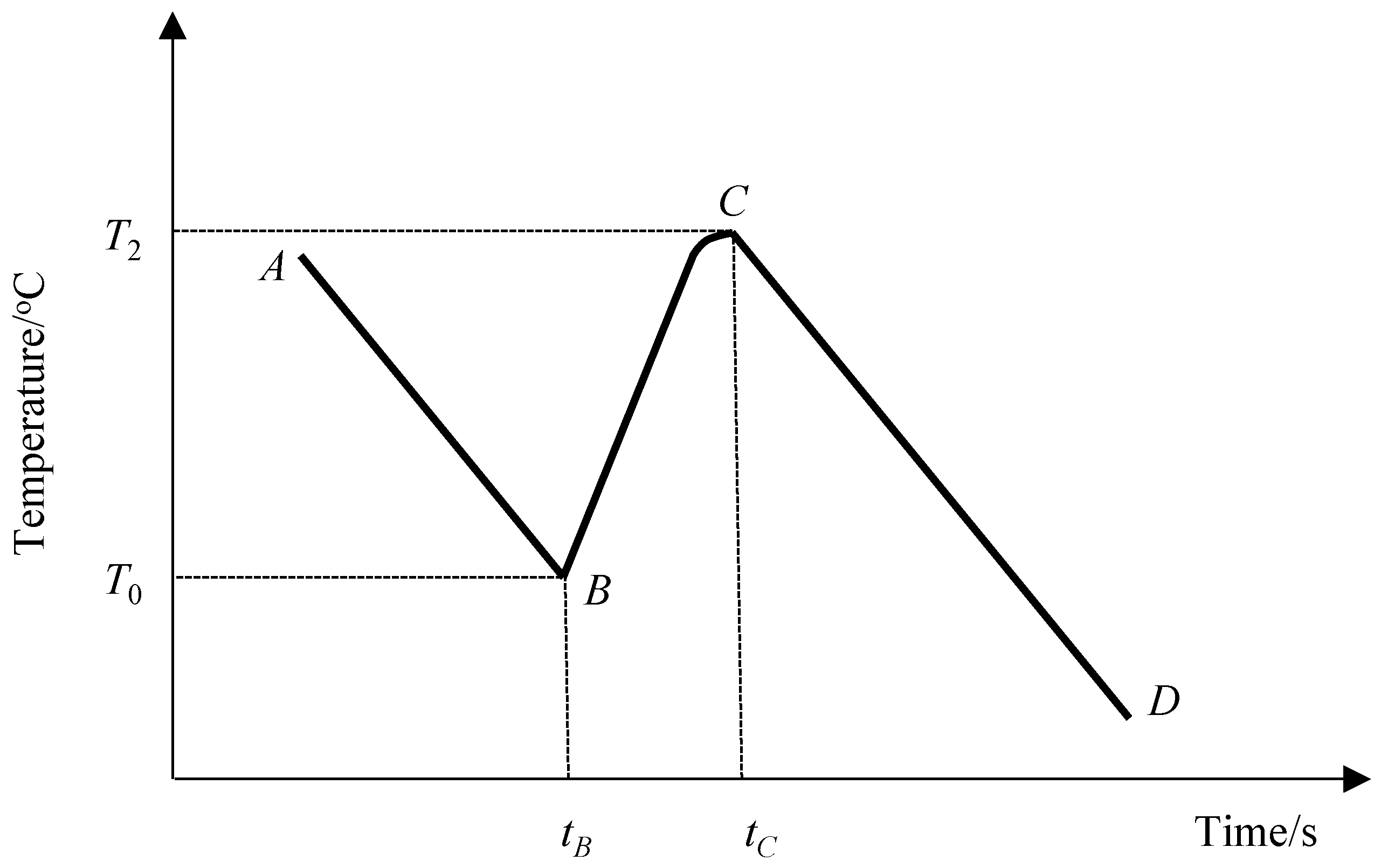
| T0 | Water temperature when specimen is put in |
| T1 | Specimen temperature when it is put into water |
| T2 | Maximum achieved temperature of the system |
| cwat | Specific heat of water, 4.2 × 10³ J/(kg·K) |
| mwat | Mass of liquid water |
| mb | Mass of vaporized water |
| Tb | Temperature of boiling water, 100 °C |
| kv | Vaporization heat of water at 100 °C, 2.57 × 10⁶ J/kg |
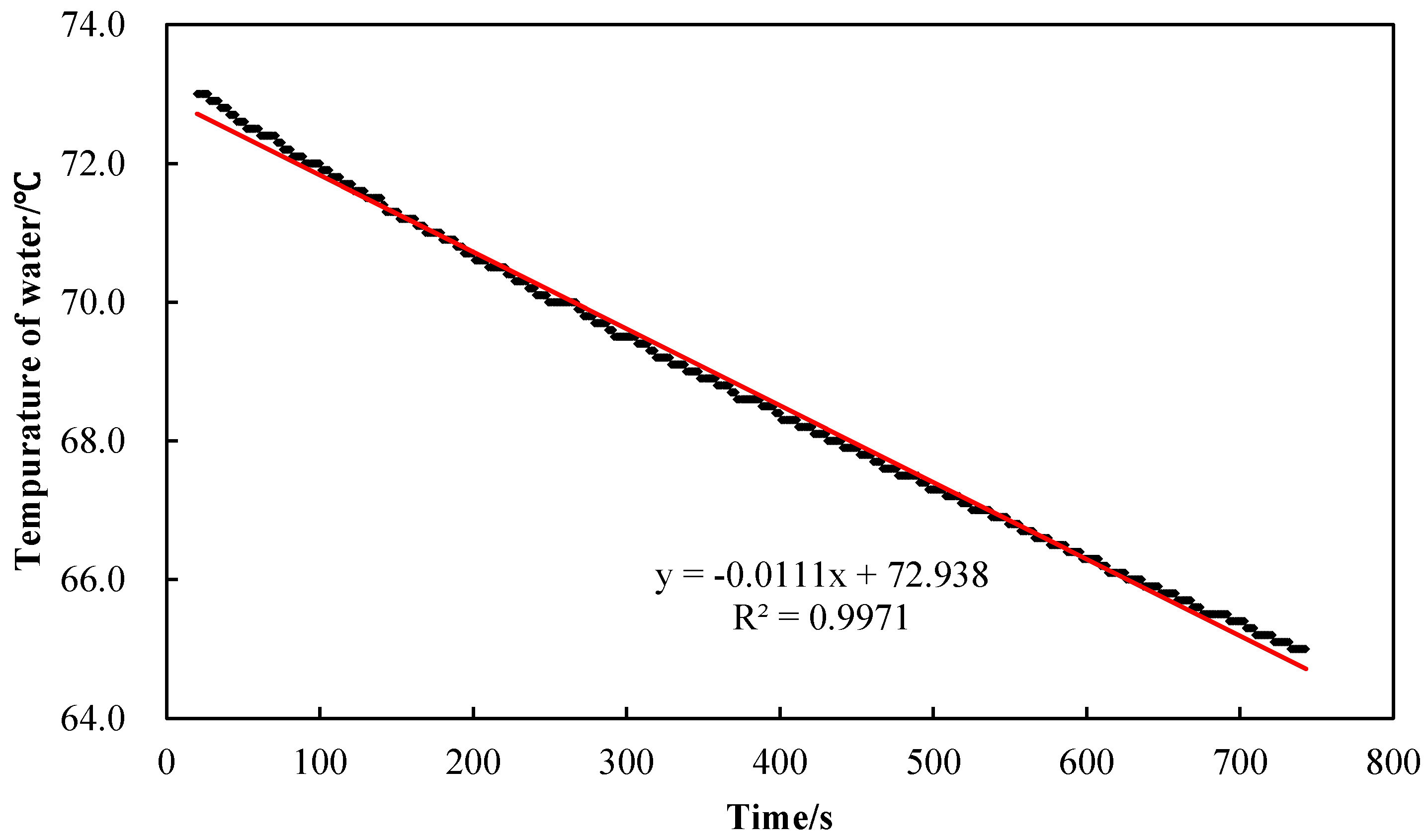
| k | Slope of range AB and range CD |
| tbc | Duration of range BC, tbc = tC − tB |
| Cement (kg) | Fly Ash (kg) | Sand (kg) | Aggregate (5–20 mm) (kg) | Aggregate (20–40 mm) (kg) | Water (kg) | Superplasticizer (kg) | Air Content | Slump (mm) |
|---|---|---|---|---|---|---|---|---|
| 210.00 | 160.00 | 996.00 | 340.00 | 509.00 | 170.00 | 2.16 | 2.10% | 95.0 |
| Specimen | m (g) | T1 (°C) | T0 (°C) | T2 (°C) | mwat (g) | mb (g) | k (°C/min) | c (J/(kg·K)) | (J/(kg·K)) | Relative Error (%) |
|---|---|---|---|---|---|---|---|---|---|---|
| GY100-1 | 353 | 100.0 | 64.5 | 64.9 | 3899 | 1 | 1.41 | 955 | 930 | 2.7 |
| GY100-2 | 346 | 100.0 | 64.5 | 64.5 | 3903 | 1 | 1.60 | 898 | 3.5 | |
| GY100-3 | 353 | 100.0 | 63.8 | 63.7 | 3919 | 1 | 1.31 | 938 | 0.8 | |
| GY200-1 | 354 | 200.0 | 64.8 | 66.4 | 5126 | 3 | 1.10 | 1024 | 995 | 2.9 |
| GY200-2 | 346 | 200.0 | 64.9 | 66.3 | 5118 | 2 | 1.02 | 975 | 2.0 | |
| GY200-3 | 353 | 200.0 | 64.8 | 66.2 | 5112 | 3 | 1.10 | 987 | 0.8 | |
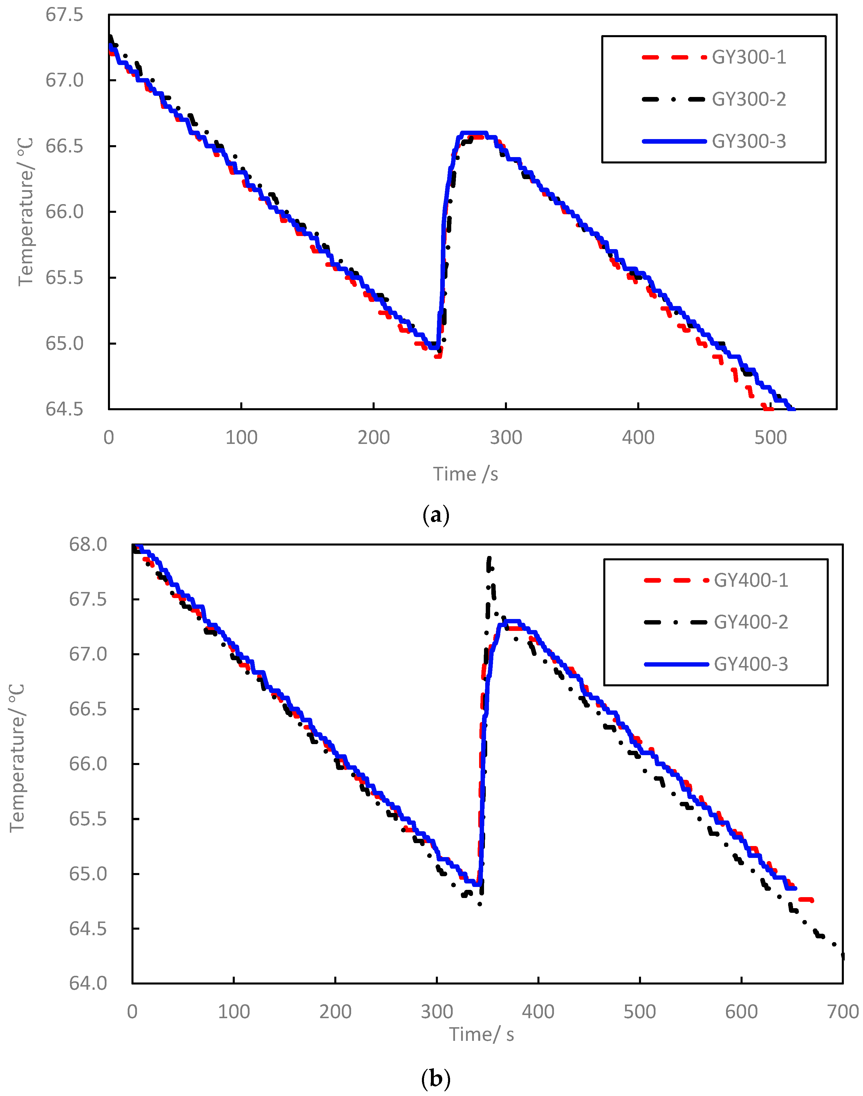
| GY300-1 | 347 | 300.0 | 64.9 | 66.6 | 9844 | 4 | 0.58 | 1093 | 1087 | 0.6 |
| GY300-2 | 344 | 300.0 | 64.9 | 66.6 | 9853 | 4 | 0.55 | 1088 | 0.1 | |
| GY300-3 | 342 | 300.0 | 65.0 | 66.6 | 9855 | 4 | 0.55 | 1080 | 0.6 | |
| GY350-1 | 353 | 350.0 | 64.6 | 66.7 | 9831 | 7 | 0.52 | 1125 | 1125 | 0.0 |
| GY350-2 | 352 | 350.0 | 64.5 | 66.5 | 9832 | 7 | 0.52 | 1125 | 0.0 | |
| GY350-3 | 348 | 350.0 | 64.4 | 66.3 | 9834 | 8 | 0.51 | 1125 | 0.0 | |
| GY400-1 | 343 | 400.0 | 65.0 | 67.2 | 9849 | 7 | 0.54 | 1097 | 1124 | 2.4 |
| GY400-2 | 341 | 400.0 | 64.7 | 67.2 | 9845 | 5 | 0.56 | 1112 | 1.0 | |
| GY400-3 | 349 | 400.0 | 64.9 | 67.3 | 9841 | 9 | 0.55 | 1162 | 3.4 | |
| GY450-1 | 354 | 450.0 | 64.9 | 67.3 | 9832 | 12 | 0.60 | 1109 | 1141 | 2.8 |
| GY450-2 | 353 | 450.0 | 65.0 | 67.8 | 9837 | 9 | 0.56 | 1150 | 0.8 | |
| GY450-3 | 346 | 450.0 | 64.5 | 67.4 | 9833 | 7 | 0.52 | 1163 | 2.0 | |
| GY500-1 | 354 | 500.0 | 65.0 | 68.1 | 9911 | 11 | 0.55 | 1165 | 1160 | 0.5 |
| GY500-2 | 344 | 500.0 | 65.1 | 68.0 | 9892 | 12 | 0.55 | 1137 | 2.0 | |
| GY500-3 | 354 | 500.0 | 64.6 | 67.8 | 9905 | 11 | 0.54 | 1177 | 1.5 | |
| GY550-1 | 342 | 550.0 | 64.6 | 68.1 | 9832 | 10 | 0.60 | 1174 | 1188 | 1.2 |
| GY550-2 | 357 | 550.0 | 65.0 | 68.6 | 9830 | 15 | 0.56 | 1205 | 1.4 | |
| GY550-3 | 352 | 550.0 | 65.1 | 68.6 | 9843 | 12 | 0.55 | 1186 | 0.2 | |
| GY600-1 | 357 | 600.0 | 65.0 | 69.2 | 9874 | 14 | 0.59 | 1211 | 1210 | 0.1 |
| GY600-2 | 344 | 600.0 | 65.0 | 68.8 | 9865 | 14 | 0.59 | 1217 | 0.6 | |
| GY600-3 | 346 | 600.0 | 65.0 | 69.2 | 9860 | 12 | 0.56 | 1201 | 0.7 |
| Specimen | M (g) | T1 (°C) | T0 (°C) | T2 (°C) | mwat (g) | mb (g) | k (°C/min) | c (J/(kg·K)) | (J/(kg·K)) | Relative Error (%) |
|---|---|---|---|---|---|---|---|---|---|---|
| HNT100-1 | 2532 | 100.0 | 65.0 | 65.8 | 9515 | 14 | 0.47 | 848 | 832 | 2.0 |
| HNT100-2 | 2526 | 100.0 | 64.7 | 65.5 | 9527 | 11 | 0.46 | 821 | 1.3 | |
| HNT100-3 | 2495 | 100.0 | 65.0 | 65.4 | 9525 | 16 | 0.46 | 826 | 0.7 | |
| HNT200-1 | 2284 | 200.0 | 65.5 | 67.7 | 9996 | 48 | 0.51 | 892 | 903 | 1.3 |
| HNT200-2 | 2433 | 200.0 | 65.0 | 68.4 | 9989 | 48 | 0.52 | 904 | 0.1 | |
| HNT200-3 | 2613 | 200.0 | 65.0 | 68.5 | 9984 | 49 | 0.52 | 914 | 1.2 | |
| HNT300-1 | 2068 | 300.0 | 65.0 | 68.0 | 19,790 | 66 | 0.26 | 1064 | 1058 | 0.6 |
| HNT300-2 | 2553 | 300.0 | 65.0 | 68.9 | 19,809 | 69 | 0.26 | 1043 | 1.4 | |
| HNT300-3 | 2578 | 300.0 | 65.0 | 69.1 | 19,783 | 72 | 0.27 | 1066 | 0.8 | |
| HNT350-1 | 2377 | 350.0 | 65.0 | 69.8 | 19,783 | 77 | 0.27 | 1080 | 1078 | 0.2 |
| HNT350-2 | 2441 | 350.0 | 65.0 | 69.8 | 19,786 | 76 | 0.27 | 1061 | 1.6 | |
| HNT350-3 | 2289 | 350.0 | 65.0 | 69.7 | 19,783 | 74 | 0.27 | 1093 | 1.4 | |
| HNT400-1 | 2312 | 400.0 | 65.1 | 70.9 | 19,763 | 81 | 0.29 | 1096 | 1095 | 0.1 |
| HNT400-2 | 2397 | 400.0 | 65.1 | 70.6 | 19,767 | 99 | 0.28 | 1093 | 0.2 | |
| HNT400-3 | 2352 | 400.0 | 65.0 | 70.8 | 19,757 | 84 | 0.28 | 1097 | 0.2 | |
| HNT450-1 | 2427 | 450.0 | 65.0 | 72.2 | 19,762 | 96 | 0.29 | 1096 | 1112 | 1.5 |
| HNT450-2 | 2223 | 450.0 | 65.0 | 71.7 | 19,753 | 92 | 0.29 | 1128 | 1.4 | |
| HNT450-3 | 2520 | 450.0 | 65.0 | 72.5 | 19,743 | 105 | 0.29 | 1113 | 0.1 | |
| HNT500-1 | 2.276 | 500.0 | 65.0 | 72.6 | 19,768 | 100 | 0.29 | 1102 | 1126 | 2.2 |
| HNT500-2 | 2.436 | 500.0 | 65.0 | 73.3 | 19,742 | 116 | 0.28 | 1133 | 0.6 | |
| HNT500-3 | 2.396 | 500.0 | 65.0 | 73.4 | 19,741 | 113 | 0.28 | 1144 | 1.6 | |
| HNT550-1 | 2346 | 550.0 | 65.0 | 74.5 | 19,737 | 120 | 0.29 | 1148 | 1141 | 0.6 |
| HNT550-2 | 2421 | 550.0 | 65.0 | 74.4 | 19,734 | 122 | 0.29 | 1116 | 2.2 | |
| HNT550-3 | 2184 | 550.0 | 65.0 | 74.1 | 19,744 | 110 | 0.29 | 1160 | 1.6 | |
| HNT600-1 | 2411 | 600.0 | 65.0 | 75.5 | 19,695 | 142 | 0.31 | 1146 | 1164 | 1.5 |
| HNT600-2 | 2218 | 600.0 | 64.9 | 74.6 | 19,719 | 134 | 0.32 | 1167 | 0.3 | |
| HNT600-3 | 2260 | 600.0 | 65.1 | 75.1 | 19,721 | 137 | 0.32 | 1178 | 1.2 |
© 2016 by the authors; licensee MDPI, Basel, Switzerland. This article is an open access article distributed under the terms and conditions of the Creative Commons Attribution (CC-BY) license (http://creativecommons.org/licenses/by/4.0/).
Share and Cite
Pan, J.; Zou, R.; Jin, F. Experimental Study on Specific Heat of Concrete at High Temperatures and Its Influence on Thermal Energy Storage. Energies 2017, 10, 33. https://doi.org/10.3390/en10010033
Pan J, Zou R, Jin F. Experimental Study on Specific Heat of Concrete at High Temperatures and Its Influence on Thermal Energy Storage. Energies. 2017; 10(1):33. https://doi.org/10.3390/en10010033
Chicago/Turabian StylePan, Jianwen, Renxin Zou, and Feng Jin. 2017. "Experimental Study on Specific Heat of Concrete at High Temperatures and Its Influence on Thermal Energy Storage" Energies 10, no. 1: 33. https://doi.org/10.3390/en10010033