Article

Low-cost Sensors Based on the GMI Effect in Recycled Transformer Cores

by
Pongsakorn Jantaratana
and
Chitnarong Sirisathitkul
*
Magnet Laboratory, Molecular Technology Research Unit, School of Science, Walailak University, Thasala District, Nakon Si Thammarat 80161, Thailand
*
Author to whom correspondence should be addressed.
Sensors 2008, 8(3), 1575-1584; https://doi.org/10.3390/s8031575
Submission received: 9 January 2008 / Accepted: 25 February 2008 / Published: 10 March 2008

Abstract

:
Sensors based on the giant magnetoimpedance (GMI) effect in silicon steels were constructed. Strips of silicon steels (0.500 mm-thick, 35.0 mm-long) with widths ranging from 0.122 to 1.064 mm were cut from recycled transformer cores. Since a maximum GMI ratio of 300% and a maximum field sensitivity of 1.5%/Oe were observed in a 1.064 mm-wide sample at 200 kHz, the 1.064 mm-wide strips were chosen as sensing elements in a slot key switch, angular velocity sensor, current sensor and force sensor. The sensing elements were integrated into electronic circuits and the changes in impedance were monitored. Variations in voltage due to these changes were typically small and must therefore be amplified by the electronic circuits. For the current sensor and force sensor, the variation in the voltage drop across the GMI sensing element had non-linear variations with either current or force and a conversion formula from a computer program was therefore needed. The performance of the systems was tested. These sensing systems were stable, highly sensitive, hysteresis-free and could be produced on a mass scale. Based on their GMI effect, the silicon steels are versatile alternative low-cost sensors.

1. Introduction

Giant magnetoimpedance (GMI) is a large change in the electrical impedance of soft ferromagnetic conductors in an applied dc magnetic field [1-2]. GMI arises from a strong dependence of the skin depth on the applied magnetic field. When a high frequency ac current is driven through a conductor, an alternating magnetic field induces a current. Since this induced current overlays the driving current, the total current decreases near the center and flows mainly in the outer regions (the skin) of the conductor. The depth at which the current density reduces to 37% of that of the surface, is called the skin depth (δ). The reduction of transverse permeability by an application of a dc magnetic field increases this skin depth and decreases the impedance. In the past few years, GMI materials in the forms of wires [3-4] and ribbons [5-6] were studied and implemented in various sensing systems [7-11]. According to our previous work in silicon steel strips cut from recycled transformer cores [12], the GMI ratio and the characteristic frequency (the frequency with a maximum GMI ratio) were dependent on the width of the strips. In the case of wide strips, the skin depth is comparable to the width at a lower frequency and the impedance is very sensitive to the magnetic field in this regime. The effects of geometry were also found in magnetic amorphous ribbons and Yabukami and co-workers used finite element analysis to optimize the structure of GMI sensors [13]. In this paper, silicon steel strips are implemented as sensing elements in systems detecting magnetic fields, electrical current, force and angular velocity.

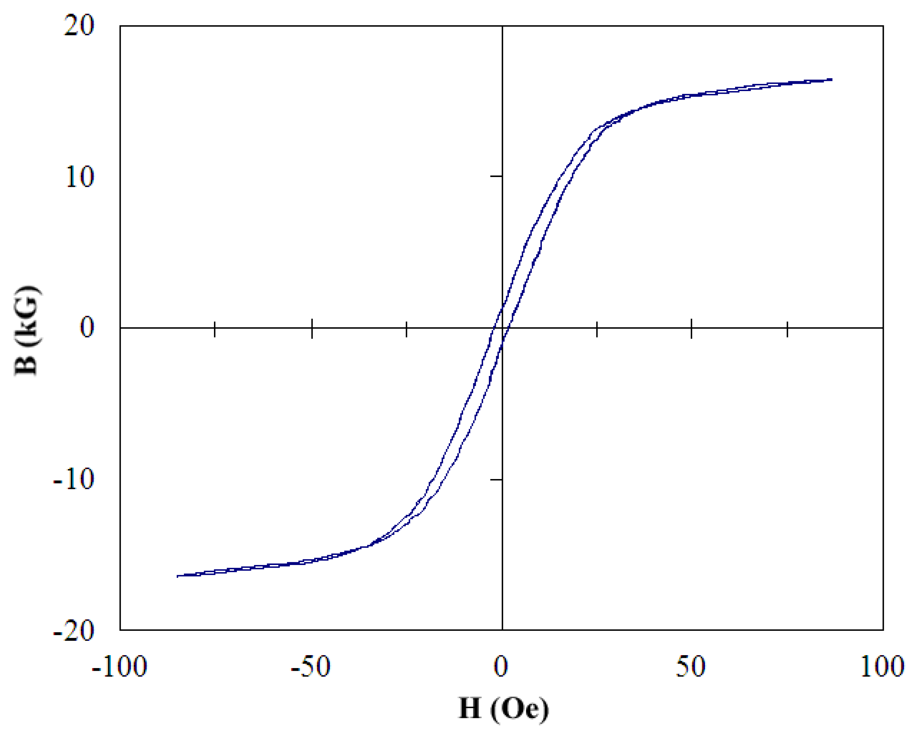
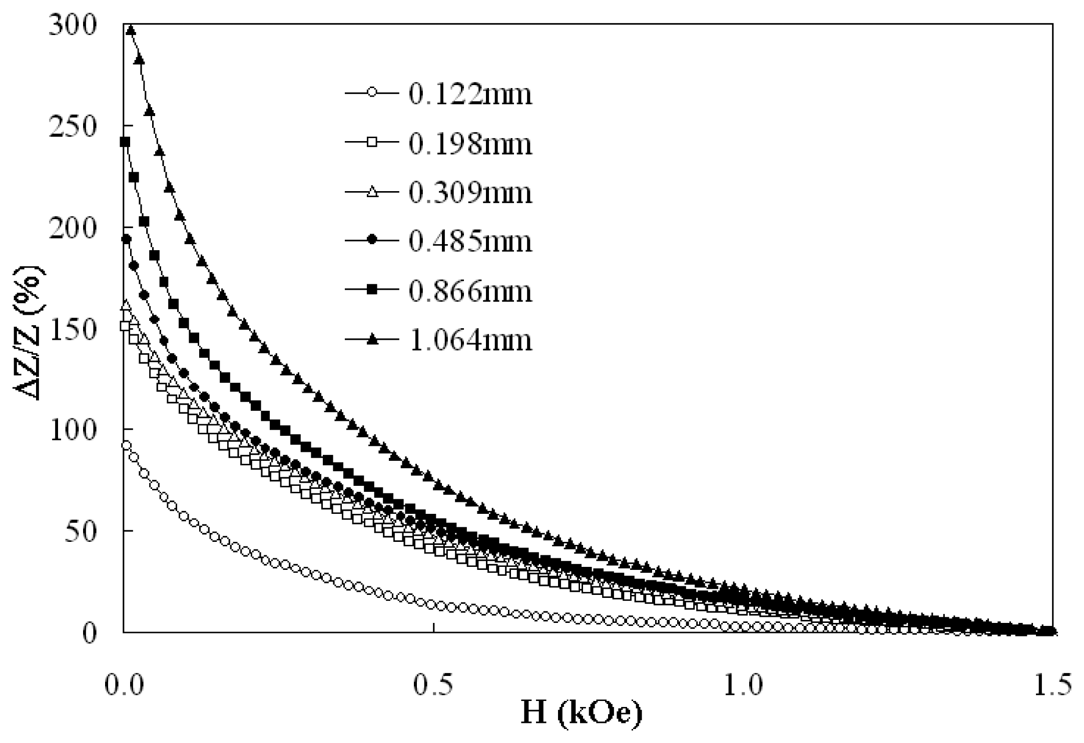
2. Magnetic and GMI properties

Silicon steel (94.5% Fe, 4.5% Si and 1% Al) strips were cut from sheets of commercial transformer cores along its easy magnetization direction with a linear precision saw (ISOMET 4000). The strips were 0.500 mm-thick, 35.0 mm-long with 6 different widths: 0.122, 0.198, 0.309, 0.485, 0.866, 1.064 mm. As exemplified by the hysteresis loop shown in Figure 1, the silicon steel samples have small losses with a coercive field of 2 Oe, a remanent induction of 1 kG and a saturation induction of 15 kG.
The GMI ratio (ΔZ/Z) is defined as 100× (ZHZ1.5 kOe)/Z1.5 kOe, where ZH and Z1.5 kOe are the impedance in the magnetic field H and in a maximum field 1.5 kOe respectively. Figure 2 shows the GMI ratio as a function of a magnetic field H supplied by an electromagnet in a longitudinal direction. Since the GMI ratio is also a function of the ac driving current, the measurements were performed at a constant 10 mA at the characteristic frequency for each sample. The 1.064 mm-wide sample exhibits a maximum GMI ratio 300%. All samples exhibit high sensitivity (evaluated from the slope of Figure 2) at low field and a maximum 1.5%/Oe is also observed in the 1.064 mm-wide sample. The sensitivity reduces at high field as the transverse permeability approaches saturation. The sensitivity of silicon steels is much less than that of typical amorphous ribbons (as high as 80%/Oe) because the amorphous ribbons possess nearly zero magnetostriction and higher permeability [14].

3. GMI sensor applications
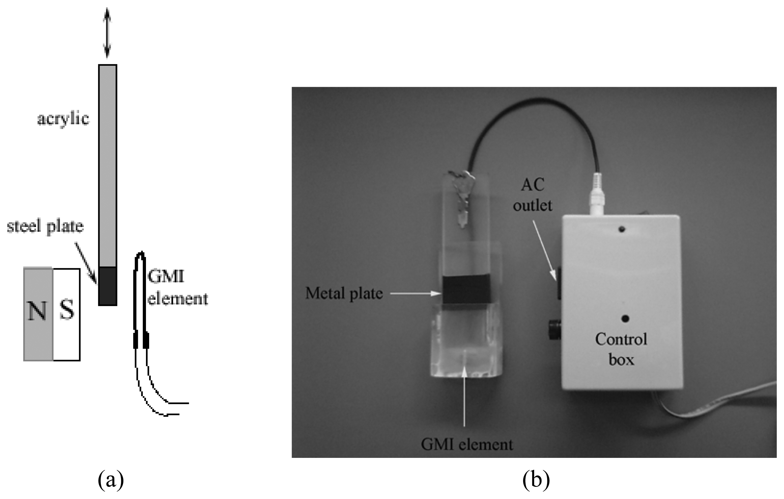
Owing to their large GMI ratio and sensitivity, strips of 1.064 mm-wide silicon steel were chosen as GMI sensing elements for a magnetic field detector in a slot key switch, an angular velocity sensor, a current sensor and a force sensor. In some cases, the strip of silicon steel was bent into U-shape and its response to magnetic field was tested because the GMI is also dependent on the mechanical stress in materials. These sensing systems are described as follows.

3.1 Slot key switch

A slot key switch as shown in Figure 3 controls the household electrical appliance by detecting a change in a magnetic field through a GMI element. The on/off state of the appliance such as electric fan and television is dependent on the presence of a metal plate in the slot because the magnetic field is reduced by the insertion of the plate between the GMI element and a permanent magnet.
A strip of silicon steel is bent into a U-shape GMI element and bound to a slot key. The GMI element is integrated into a circuit as shown in Figure 4. The circuit consists of a 50 kHz current pulse generator, a potential divider, an inverting amplifier, a differential amplifier and a transistor connected as a common-emitter amplifier. Without a metal plate between the GMI element and the magnet, the potentiometer P1 is adjusted so that the output from the differential amplifier is minimal and the transistor is in a cut-off state. A magnetic field of 50 Oe is enough to switch the relay off. When a user inserts a metal plate into the slot, the magnetic field through the GMI element is shielded and the impedance of the GMI element consequently increases. The change in a voltage drop across the GMI element is successively amplified resulting in a base current of the transistor which is high enough to switch the relay on. In prototype testing, a light bulb was effectively turned on and off by inserting and removing a metal plate between the permanent magnet and the GMI element. However, the stability of the slot key switch depends on the environmental temperature. If the temperature varies more than 5 °C, potentiometer adjustment is fitfully required. Furthermore, it was shown by Honkura [15] that temperature stability of GMI sensors can vastly be improved by modifications of the electric circuit such as the replacement of high temperature-dependent components.

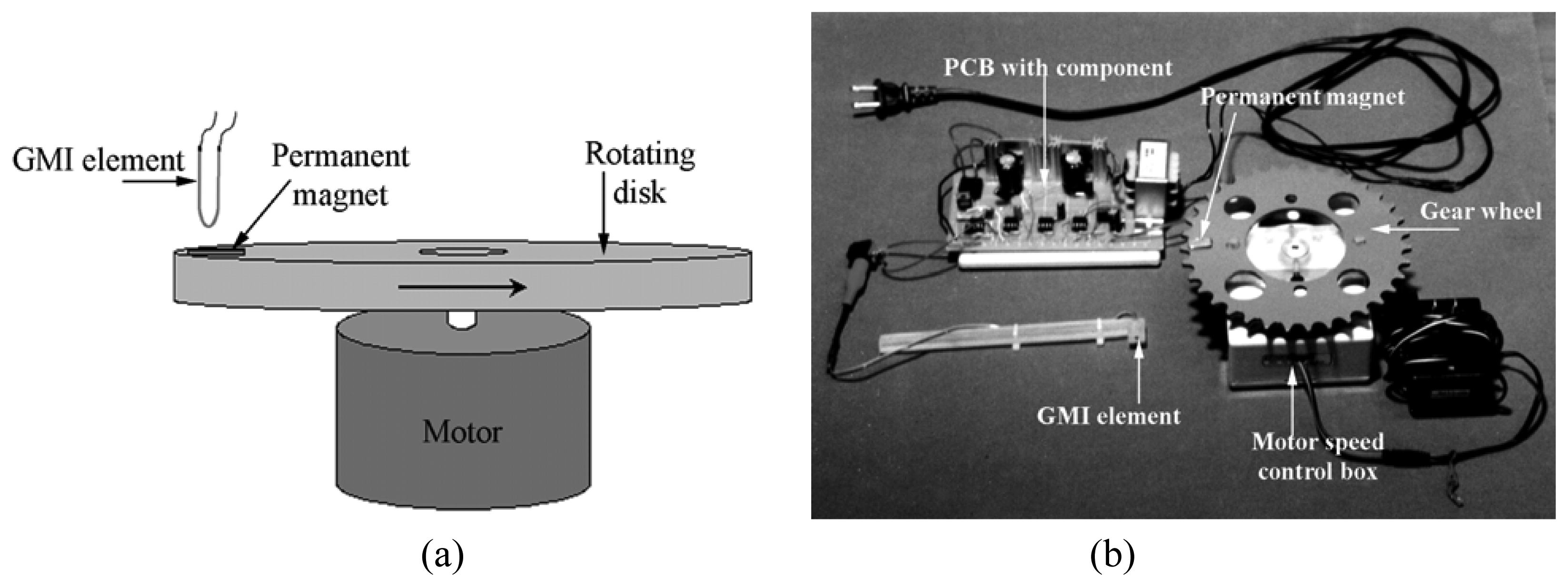
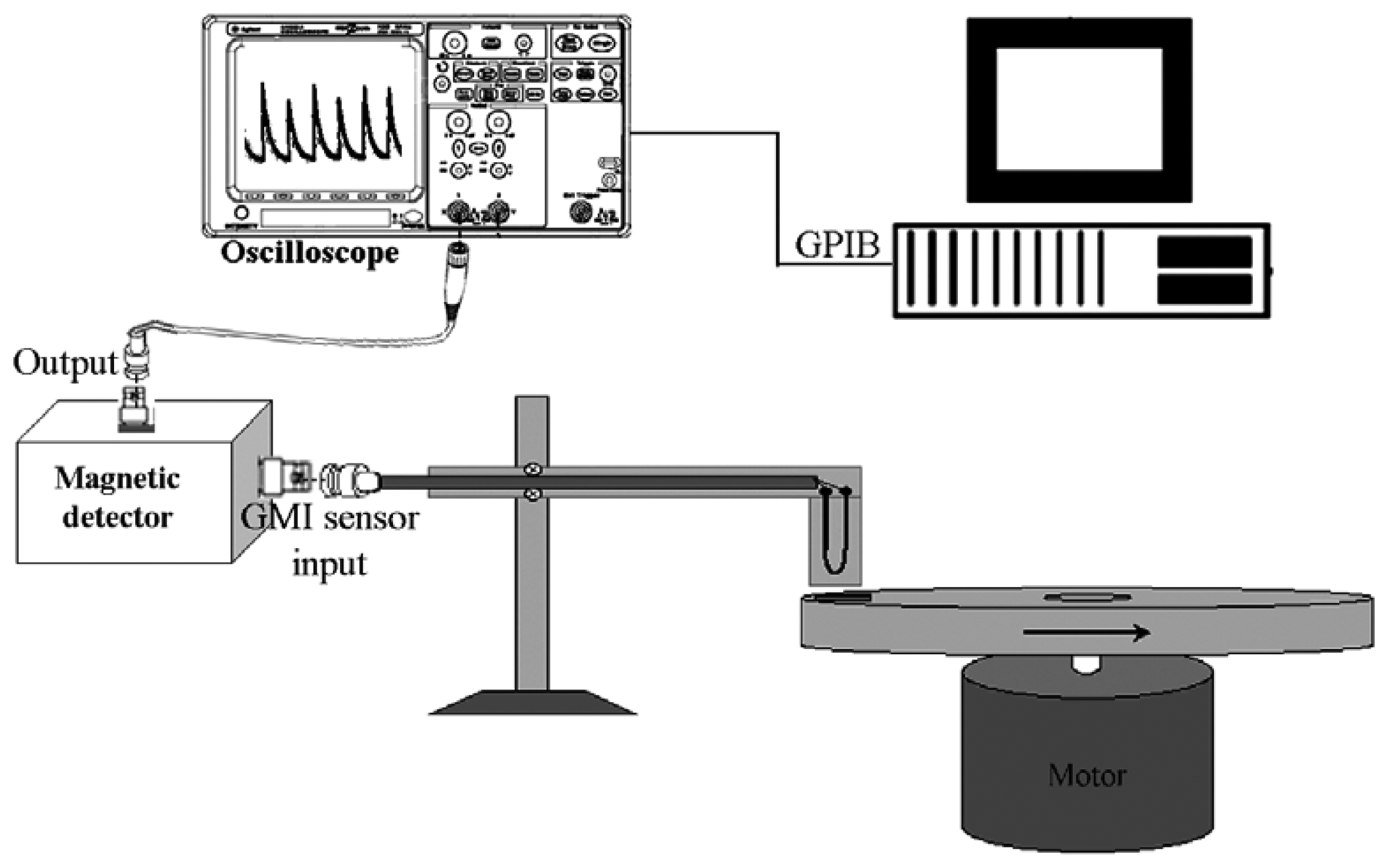
3.2 Angular velocity sensor
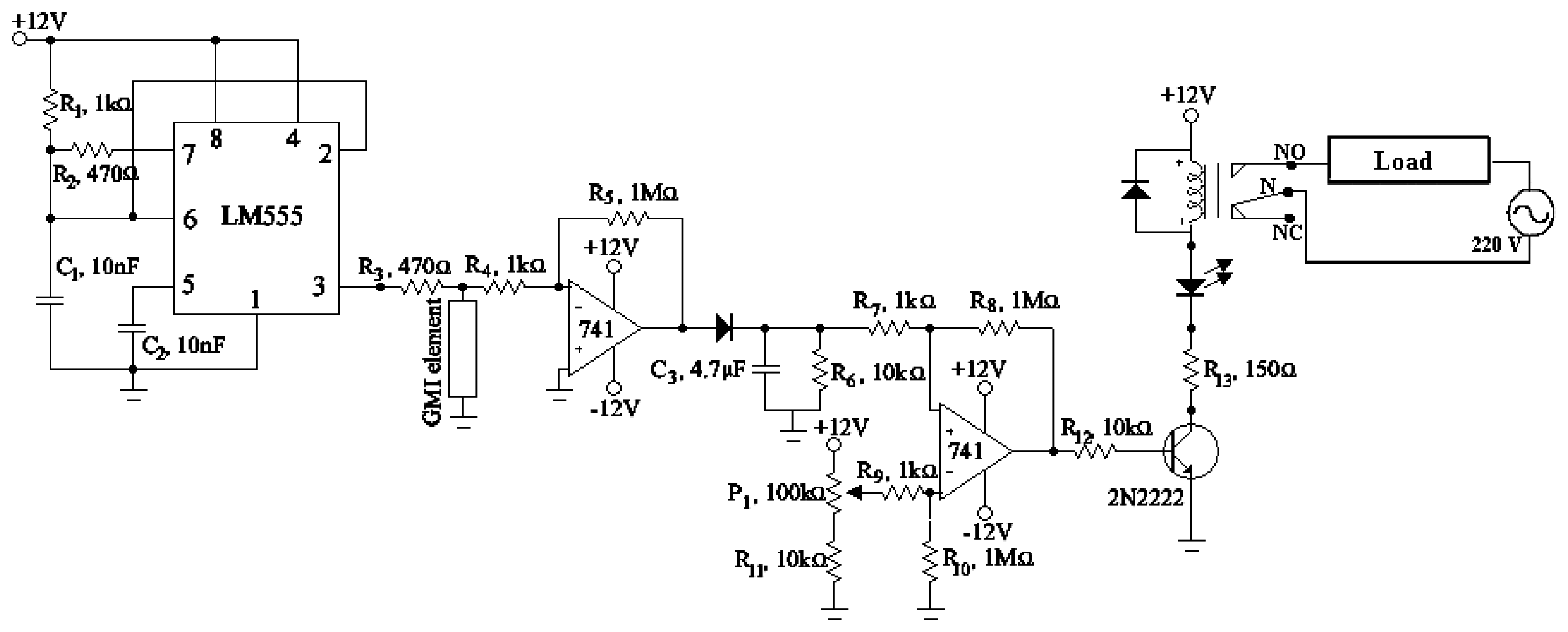
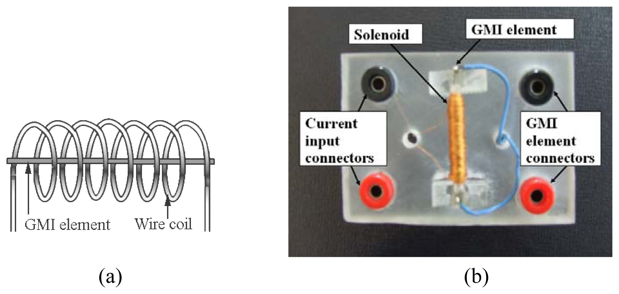
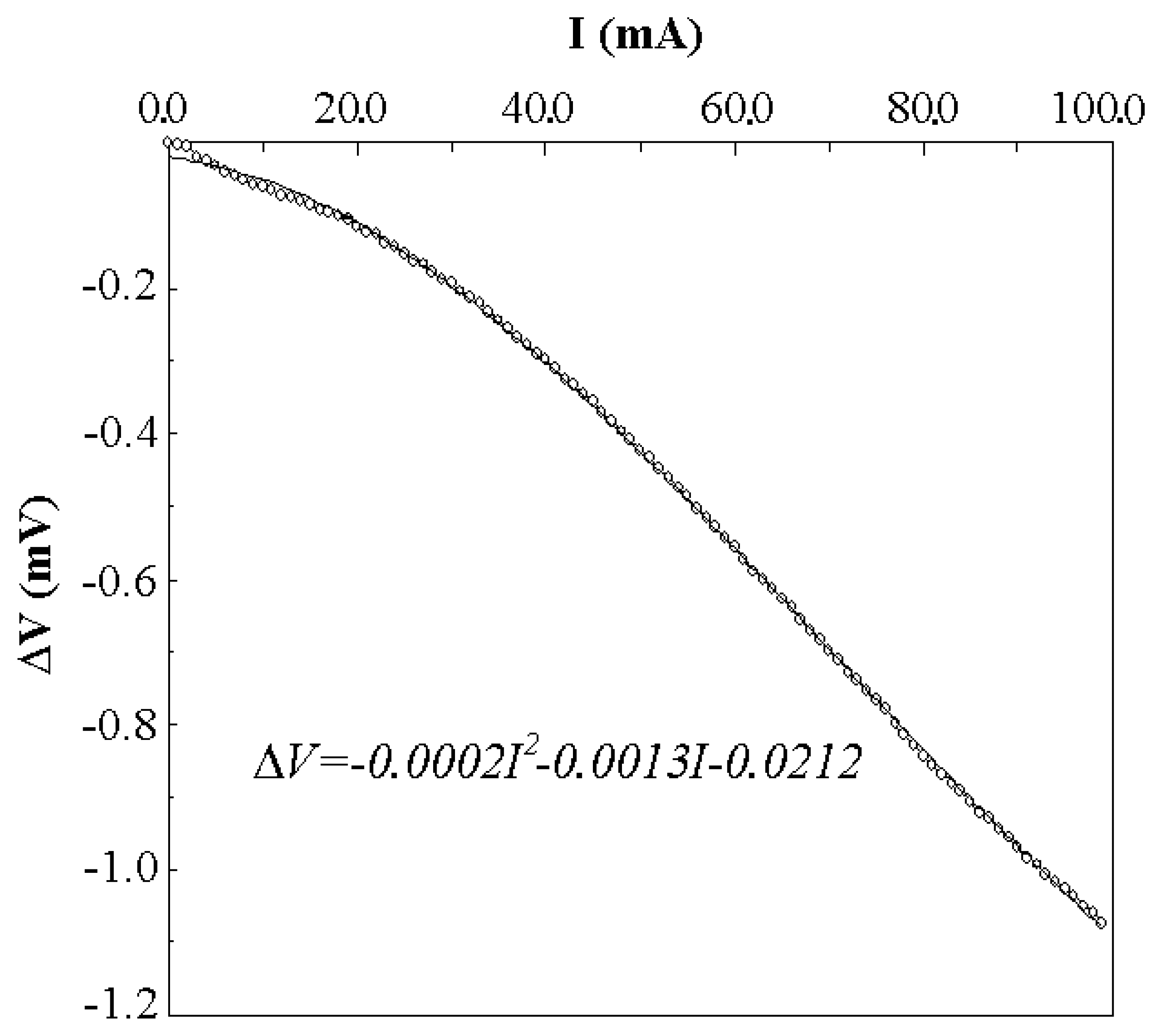
The configuration and photograph of a GMI angular velocity sensor are shown in Figure 5. A permanent magnet is mounted on a rotating disk and a piece of U-shape silicon steel is used as a sensing element. The GMI element experiences a change in impedance by the approach of the magnetic part of the disk and the frequency or angular velocity of the rotation can be interpreted from the oscilloscope.
An angular velocity sensor circuit has some features in common with Figure 4, but a Wien bridge oscillator producing a 50 kHz sine wave signal replaces the current pulse generator. The output of the differential amplifier is directly connected to an oscilloscope (Agilent 54622A) with a GPIB interface in order to measure the frequency of the rotating disk. Figure 6 shows a schematic diagram of the angular velocity sensor system. When a nonmagnetic part of the rotating disk passes the GMI element, the reference voltage is adjusted at the potentiometer P1 until the reading voltage of the oscilloscope is zero. As the magnet on the disk approaches to the GMI element, the impedance of the GMI element decreases and the output voltage of the differential amplifier increases as a result. The frequency of the oscillating voltage displayed on the oscilloscope is directly proportional to the rotational speed of the rotating disk measured in revolutions per minute (rpm). From tests on the prototype, a maximum angular velocity of about 200 rpm could be measured.

3.3 Current sensor

The current sensor using a GMI element is assembled as shown in Figure 7. When a measuring current passes through a solenoid, a magnetic field is generated and detected by the GMI element rigidly mounted along the axis of the solenoid.
A strip of silicon steel is mounted along the air core of a 3.0 mm-diameter, 35.0 mm-long solenoid with 200 turns of copper wire. According to Figure 8, the GMI element is connected to a function generator (Agilent 33120A) and a multimeter (Agilent 34401A) with a GPIB interface. The function generator sends a 0.35 V, 200 kHz sine wave signal through a 4.7 Ω-resistor and the GMI element. A voltage drop across the GMI element is measured by the multimeter at various currents I (from 0 to 100.0 mA) supplied by a constant current source (Keithley 220). The variation in the voltage ΔV=VIV0, where VI and V0 are voltage drops across the GMI element when the current I and no current flow through the solenoid respectively, is then plotted against the current as shown in Figure 9. The system can then be used to measure any current up to 100.0 mA using a conversion formula obtained from this curve and displaying the current on a computer monitor. In order to test the prototype, a current of 50.0 mA was repeatedly measured by the GMI current sensor 30 times. The average measured value was 50.3 mA with a standard deviation of 0.2 mA. The sensitivity of this current sensor can be improved by increasing the number of turns of the solenoid. According to a recent work by Zhan and co-workers, a GMI current sensor based on an annealed Co66.3Fe3.7Si12B18 amorphous ribbon toroidal core had the sensitivity as much as 0.67 V/A with a linear response in a range of ± 2.5 A [16].

3.4 Force sensor

A beam-type force sensor is assembled as shown in Figure 10. A 4.5 cm-diameter permanent magnet is mounted on the upper beam (7.5 mm-diameter aluminum rod) and a U-shape GMI sensing element is affixed at the lower cantilever beam (5.0 mm-diameter acrylic rod). Without the applied force at the lower cantilever beam, the GMI element senses a magnetic field of about 150 Oe from the permanent magnet. When a force F is applied at the lower cantilever beam (15.0 cm-away from the support rod), the beam is bent and the impedance of the GMI element increases because of a reduction in the magnetic field.
The GMI element is integrated into a system similar to the current sensor. The voltage drop across the GMI element at different forces (from 0 to 1.76 N) is measured using the multimeter. Figure 11 shows the variation in voltage ΔV=VFV0 plotted against the force, where VF and V0 represent the voltage drop across the GMI element when the force F and no force are applied to the lower cantilever beam respectively. The obtained formula can then be used to convert the voltage reading to a force in a real measurement. The performance of the prototype was tested by measuring a force of 0.88 N 30 times. The average measured force was 0.88 N with a standard deviation of 0.02 N. Both force sensor and current sensor have linear outputs only in a limited range and their linearity may be increased by using a feedback circuit as suggested by Nesteruk and co-workers [17].

4. Conclusions

Prototypes of GMI sensing systems have been developed using silicon steel strips from recycled transformer cores. A sine wave or a pulse signal is sent to a silicon steel sensing element and a variation voltage due to a change in impedance of the sensing element is detected by a voltage sensing circuit or a multimeter. These GMI sensing systems still rely on electronic circuits and computer programs because the impedance of silicon steel is low and has non-linear variations. Frequent calibration is also required because time-dependent stress and temperature have effects on the performances of the sensors. Nevertheless, the silicon steels possess several advantages for measurement and control applications since they exhibit high field sensitivity with no hysteresis. Because silicon steels are widely available at low cost, these GMI sensors may become commercially competitive to other magnetic and optical sensors.

Supplementary Material

  • Supplementary Material: Supplementary material file for Figure 3: http://www.mdpi.org/sensors/papers/8031575-1.mpg; for Figure 5: http://www.mdpi.org/sensors/papers/s8031575-2.mpg.

  • Acknowledgments

    This work was supported by Walailak University's research unit fund. The authors would like to thank Dr. David Harding for his proof-reading.

    References

    1. Beach, R.S.; Berkowitz, A. E. Giant magnetic field dependent impedance of amorphous FeCoSiB wire. Appl. Phys. Lett. 1994, 64, 3652–3654. [Google Scholar]
    2. Panina, L. V.; Mohri, K. Magnetoimpedance effect in amorphous wires. Appl. Phys. Lett. 1994, 65, 1189–1191. [Google Scholar]
    3. Sirisathitkul, C.; Jantaratana, P. Giant magnetoimpedance of electrodeposited Co/Cu/Co on Ag wires. J. Phys. D: Appl. Phys. 2007, 40, 4431–4435. [Google Scholar]
    4. Pal, S. K.; Manik, N. B.; Mitra, A. Dependence of frequency and amplitude of the ac current on the GMI properties of Co based amorphous wires. Mater. Sci. Eng. A 2006, 415, 195–201. [Google Scholar]
    5. Phan, M. H.; Peng, H. X.; Wisnom, M. R.; Yu, S. C.; Kim, C. G.; Nghi, N. H. Effect of annealing temperature on permeability and giant magneto-impedance of Fe-based amorphous ribbon. Sens. Actuat. A 2006, 129, 62–65. [Google Scholar]
    6. Garcia-Arribas, A.; Saad, A.; Orue, I.; Kurlyandskaya, G. V.; Barandiaran, J. M.; Garcia, J. A. Non-linear magnetoimpedance in amorphous ribbons: Large asymmetries and angular dependence. Sens. Actuat. A 2006, 129, 275–278. [Google Scholar]
    7. Kurlyandskaya, G. V.; Miyar, V. F. Surface modified amorphous ribbon based magnetoimpedance biosensor. Biosens. Bioelectron. 2007, 22, 2341–2345. [Google Scholar]
    8. Chiriac, H.; Herea, D. D.; Corodeanu, S. Microwire array for giant magneto-impedance detection of magnetic particles for biosensor prototype. J. Magn. Magn. Mater. 2007, 311, 425–428. [Google Scholar]
    9. Zhao, Z.; Li, Y. M.; Cheng, J.; Xu, Y. F. Current sensor utilizing giant magneto-impedance effect in amorphous ribbon toroidal core and CMOS inverter multivibrator. Sens. Actuat. A 2007, 137, 64–67. [Google Scholar]
    10. Kollu, P.; Kim, C.; Yoon, S. S.; Kim, C. O. Highly sensitive giant magneto impedance sensor with LC pick-up circuit. Sens. Lett. 2007, 5, 157–161. [Google Scholar]
    11. Tan, K.; Komakine, T.; Yamakawa, K.; Kayano, Y.; Inoue, H.; Yamaguchi, M. Detection of high-frequency magnetic fields by a GMI probe. IEEE Trans. Magn. 2006, 42, 3329–3331. [Google Scholar]
    12. Jantaratana, P.; Sirisathitkul, C. Giant magnetoimpedance in silicon steels. J. Magn. Magn. Mater. 2004, 281, 399–404. [Google Scholar]
    13. Yabukami, S.; Mawatari, H.; Horikoshi, N.; Murayama, Y.; Ozawa, T.; Ishiyama, K; Arai, K. I. A design of highly sensitive GMI sensor. J. Magn. Magn. Mater. 2005, 290-291, 1318–1321. [Google Scholar]
    14. Alves, F.; Bensalah, A. D. New 1D–2D magnetic sensors for applied electromagnetic engineering. J. Mater. Proc. Tech. 2007, 181, 194–198. [Google Scholar]
    15. Honkura, Y. Development of amorphous wire type MI sensors for automobile use. J. Magn. Magn. Mater. 2002, 249, 375–381. [Google Scholar]
    16. Zhan, Z.; Yaoming, L.; Jin, C.; Yunfeng, X. Current sensor utilizing giant magneto-impedance effect in amorphous ribbon toroidal core and CMOS inverter multivibrator. Sens. Actuat. A 2007, 137, 64–67. [Google Scholar]
    17. Nesteruk, K.; Kuzminski, M.; Lachowicz, H. K. Novel magnetic field meter based on giant magneto-impedance (GMI) effect. Sens. Trans. Mag. 2006, 65, 515–520. [Google Scholar]
    Figure 1. Longitudinal hysteresis loop of a silicon steel strip obtained by fluxmetric induction method at room temperature.
    Figure 1. Longitudinal hysteresis loop of a silicon steel strip obtained by fluxmetric induction method at room temperature.
    Sensors 08 01575f1
    Figure 2. Dependence of GMI ratio (for samples of varying widths at their characteristic frequencies) on the longitudinal magnetic field obtained by the auto balancing bridge method at room temperature.
    Figure 2. Dependence of GMI ratio (for samples of varying widths at their characteristic frequencies) on the longitudinal magnetic field obtained by the auto balancing bridge method at room temperature.
    Sensors 08 01575f2
    Figure 3. (a) Configuration and (b) photograph of a GMI slot key switch (a file showing the operation of this switch is available as supplementary material: http://www.mdpi.org/sensors/papers/s8031575-1.mpg, 5369 KB).
    Figure 3. (a) Configuration and (b) photograph of a GMI slot key switch (a file showing the operation of this switch is available as supplementary material: http://www.mdpi.org/sensors/papers/s8031575-1.mpg, 5369 KB).
    Sensors 08 01575f3
    Figure 4. Circuit diagram of a slot key switch with U-shape silicon steel as a GMI element.
    Figure 4. Circuit diagram of a slot key switch with U-shape silicon steel as a GMI element.
    Sensors 08 01575f4
    Figure 5. (a) Configuration and (b) photograph of an angular velocity sensor (a file showing the operation of this sensor is available as supplementary material: http://www.mdpi.org/sensors/papers/s8031575-2.mpg, 5349 KB).
    Figure 5. (a) Configuration and (b) photograph of an angular velocity sensor (a file showing the operation of this sensor is available as supplementary material: http://www.mdpi.org/sensors/papers/s8031575-2.mpg, 5349 KB).
    Sensors 08 01575f5
    Figure 6. Schematic diagram of an angular velocity sensor system.
    Figure 6. Schematic diagram of an angular velocity sensor system.
    Sensors 08 01575f6
    Figure 7. (a) Configuration and (b) photograph of a current sensor.
    Figure 7. (a) Configuration and (b) photograph of a current sensor.
    Sensors 08 01575f7
    Figure 8. Schematic connection of a GMI based current sensor system.
    Figure 8. Schematic connection of a GMI based current sensor system.
    Sensors 08 01575f8
    Figure 9. Variation of voltage drop across a GMI element in a current sensor as a function of the current.
    Figure 9. Variation of voltage drop across a GMI element in a current sensor as a function of the current.
    Sensors 08 01575f9
    Figure 10. (a) Configuration and (b) photograph of a force sensor.
    Figure 10. (a) Configuration and (b) photograph of a force sensor.
    Sensors 08 01575f10
    Figure 11. Variation of voltage drop across a GMI element in a force sensor as a function of the force.
    Figure 11. Variation of voltage drop across a GMI element in a force sensor as a function of the force.
    Sensors 08 01575f11

    Share and Cite

    MDPI and ACS Style

    Jantaratana, P.; Sirisathitkul, C. Low-cost Sensors Based on the GMI Effect in Recycled Transformer Cores. Sensors 2008, 8, 1575-1584. https://doi.org/10.3390/s8031575

    AMA Style

    Jantaratana P, Sirisathitkul C. Low-cost Sensors Based on the GMI Effect in Recycled Transformer Cores. Sensors. 2008; 8(3):1575-1584. https://doi.org/10.3390/s8031575

    Chicago/Turabian Style

    Jantaratana, Pongsakorn, and Chitnarong Sirisathitkul. 2008. "Low-cost Sensors Based on the GMI Effect in Recycled Transformer Cores" Sensors 8, no. 3: 1575-1584. https://doi.org/10.3390/s8031575

    Article Metrics

    Back to TopTop