Simulation Study of Nano Aqueous Flow Sensor Based on Amperometric Measurement

1
Department of Biomedical Engineering, Zhejiang University, 38 ZheDa Road, Hangzhou 310027, PR China
2
Women’s Hospital, Zhejiang University, 2 Xueshi Road, Hangzhou 310006, PR China
*
Author to whom correspondence should be addressed.
Sensors 2006, 6(5), 473-479; https://doi.org/10.3390/s6050473
Submission received: 10 November 2005
/
Revised: 13 March 2006
/
Accepted: 17 March 2006
/
Published: 6 April 2006
Abstract
:In this paper, a novel nano aqueous flow sensor which consists of two closely spaced amperometric sensors is investigated by digital simulation. The simulation results indicate that the ratio of the responses of two closely spaced amperometric sensors is only related to flow rates in the channel, insensitive to the analyte concentration in the solution. By comparing the output of two amperometric sensors, the flow rate in the channel can be deduced. It is not necessary to determine the analyte concentration in advance. The simulation results show it is able to detect flow rate by in the range of several nano-liters per minute when the distance between the working electrodes of two amperometric sensors is 200 nm and the cross-section of the channel is 1 μm × 1 μm.
1. Introduction
Flow measurements have become increasingly important in the micro/nano systems for chemical analysis, drug delivery and so on [1,2]. Presently thermal measurement is still the main choice in measuring micro/nano flow of aqueous liquids [3,4]. Thermal measurement has advantages such as sensing very low flow rate. However, in order to achieve good thermal isolation, complicated MEMS structures are necessary, which are quite difficult to be implemented. In 2002 we reported an electrochemical time-of-flight (TOF) flow sensor [5]. This flow sensor consists of two electrochemical cells. The upstream cell functions as an in-situ oxygen producer while the downstream cell is used to detect the produced the oxygen pulse. Since the geometry setup of the micro-channel is known, the flow rate is derived from the time difference between produce and detection. Unlike thermal pulse, oxygen pulse does not diffuse into the wall of micro-channel. There is no any isolation structure is required in this electrochemical TOF flow sensor. The flaw of this electrochemical TOF flow sensor is that produced oxygen pulse sometimes forms a bulb and blocks the micro-channel.
Collins et al proposed a microfluidic flow transducer based on the measurement of electrochemical admittance [6]. In this case, the AC admittance of a pair of gold electrodes in the micro-channel is monitored, which is related to the flow rate. There is no isolation structure required in this electrochemical flow sensor. However, the AC admittance of the electrodes is related to liquid components too. With this method, the concentration of electrochemical components in liquid has to be determined in advance. Amatore et al also proposed an electrochemical flow sensor which exploits the electrochemical cycling of a redox couple between closely spaced band electrodes [7]. The cycling efficiency is related both to the electrode gaps and the flow rate (convective transportation). In this approach, a redox couple in liquid is elementary.
Recently, we proposed a micro electrochemical flow sensor which consists of two closely spaced amperometric oxygen sensors [8]. The distance between the working electrodes of these two oxygen sensors is 10 μm and the across section of the micro-channel is 100 μm × 100 μm. During measurement, the upstream amperometric oxygen sensor consumes a part of dissolved oxygen [9]. In this way, the response of downstream amperometric is reduced since both sensors are closely spaced. The simulation results show that although the response of each oxygen sensor is related to both the oxygen concentration and flow rate, the ratio of the responses of these two oxygen sensors is only determined by flow rates in the micro-channel. Therefore, it is not necessary to know the analyte concentration in advance. By comparing the output of two amperometric sensors, the flow rate in the channel can be deduced. The advantage of this flow sensor is that no complicated micro-structure is required and oxygen concentration in the solution is not needed to be determined in advance.
In this paper, we further investigate this type of flow sensor in nano-meter scale by digital simulation. In micron scale, it is possible to neglect the diffusion in flow direction because convection is usually very fast compared to this diffusion. However, since the diffusion time is proportional to the square of the distance, diffusion plays an important role in mass transportation when the distance between the working electrodes of two amperometric sensors are in nano-meter range. In this paper, a new model is set up and corresponding digital simulations are carried out.
2. Sensing principle and simulation results
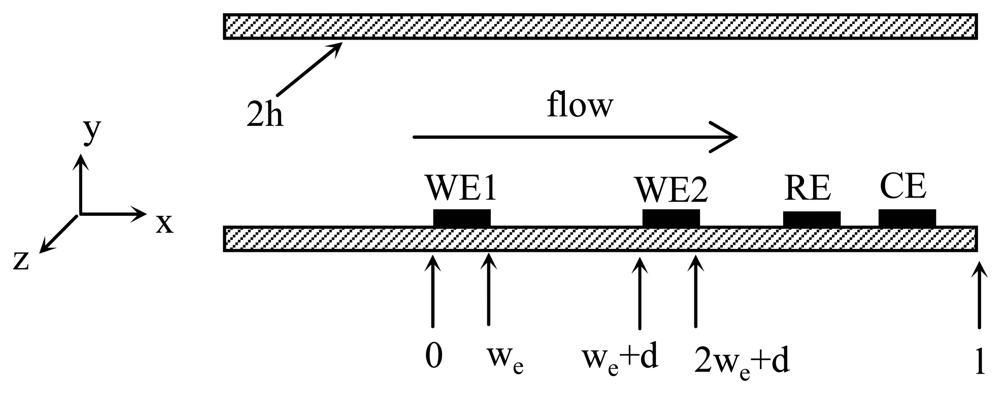
The proposed flow sensor consists of two amperometric sensors integrated in the flow channel, which is shown schematically as figure 1. Theoretically, any amperometric sensor can be used for the proposed flow sensor. However, normally there is always some dissolved oxygen in the aqueous solution. Meanwhile, amperometric oxygen sensor has been well studied. Therefore, amperometric oxygen sensor is used during the modeling.
An amperometric oxygen sensor consists of the working electrode, the reference electrode and the counter electrode. Since both amperometric sensors are closely spaced in the same aqueous solution, one set of counter electrode and reference electrode is enough, which is shared by two working electrodes.
On application of a negative potential on the working electrodes, oxygen is reduced and a current passing through:
The current of the oxygen sensor is determined by the oxygen concentration in the solution, the mass transportation of oxygen in the channel and the electrode kinetics.
The general equation describing diffusion and convection for a species in a channel is:
where c is the concentration of oxygen, D is the diffusion coefficient, vx , vy , and vz represent the solution velocity profile in the x, y and z direction. In the case of a flow sensor in the channel, this general equation can be simplified in a number of ways. First, laminar flow prevails in the micro/nano-channel because Reynolds number is generally smaller than 2100. The velocities in y and z direction can be omitted. The profile of the solution velocity along y direction is represented by:
where v0 is the velocity at the center of the channel, y ′ = y − h and h is the half height of the channel. Second, if the length of electrodes of the oxygen sensor in z direction is smaller than the width of the channel, it is also possible to neglect the diffusion in z direction. Furthermore, as long as the time of the negative potentials applied on the working electrode is long enough, this is a steady state problem. All these simplifications reduce the Eq. 2 into a two-spatial problem along the longitudinal cross section of the nano-channel:
The boundary conditions are as follow:
Equations 5 and 7 specify the boundary condition at the working electrode of the amperometric oxygen sensor. Here it is supposed that the kinetics of the electrode reaction is fast enough to deplete oxygen immediately. The oxygen concentration at the surface of the working electrode is zero. Eq. 7, 8 and 9 specify the boundary condition at the top and bottom of the channel. There is no flux of oxygen through the wall of the channel. Eq. 10 corresponds to the flow of the bulk solution from the left side. cbulk is the dissolved oxygen concentration in the solution.
A program was developed in a MatLab environment to numerically calculate the distribution of oxygen in the nano-channel and the current passing through the working electrodes based on finite difference method. During the simulation, the channel dimension is h = 500 nm, l = 3 nm, we = 200 nm and d = 200 nm. The concentration of dissolved oxygen, cbulk, is set absolutely. For Solution 1, cbulk is set at 1 while for Solution 2 cbulk is set at 2. The simulated results are summarized in Table 1. Here the flow rate is v0, the velocity at the center of the channel with dimension of cm/s. The relationship between v0 and the bulk flow rate Vvolume is:
where h is the half height of the channel and L is the width of the channel. If h = 500 nm and L = 1 μm, Vvolume is 1.6 nl/min when v0 is equal to 1 cm/sec. iup and idown are the currents passing through the upstream and down stream oxygen sensors, respectively. The current passing through the working electrode of oxygen, i, is calculated according to the Faradic law:
where F is the Faraday constant and A the area of the working electrode.
It is shown in the Table 1 that the current passing through each amperometric oxygen sensor is related both to the flow rate and the oxygen concentration in the solution. Therefore, it is impossible to use amperometric sensor to detect flow rate unless the analyte concentration has been determined in advance. However, the ratio of the current passing through two sensors is only related to the flow rate, insensitive to the oxygen concentration in the solution. The physical explanation for this phenomenon is as follow. Since the distance between the working electrodes are in nanometer range, when upstream solution arrives at the working electrode of downstream sensor, the oxygen consumed by upstream sensor will not be fully compensated by diffusion in y direction yet. In this way, the oxygen concentration around the downstream sensor is different from that in bulk solution. This difference is related to the distance of two oxygen sensors and also the flow rate. The distance between the oxygen sensors has been determined during the fabrication. Therefore, the ratio of currents between upstream working electrode and downstream working electrode is determined only by the flow rate. By comparing the output of two oxygen sensors, the flow rate in the channel can be deduced. Furthermore, as long as the responses of both sensors to the dissolved oxygen are linear (i ∝ coxygen), the alteration of dissolved oxygen concentration has the same effect on them. The current ratio between these two sensors is not affected by oxygen concentration. In this way, it is not necessary to know the exact oxygen concentration in the solution any more.
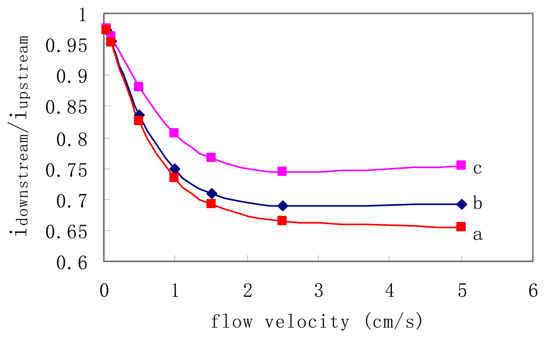
Further simulation was also carried out to investigate the influence of the distance between two working electrodes on the measurement sensitivity. The results are shown in Fig. 2. For curve a, the distance between two working electrodes is 100 nm, while for curve b and c are 200 nm and 500 nm, respectively. In each curve, the current ratio is decreased with the increase of flow rate. However, the response is saturated when the flow velocity v0 is faster than 2.5 cm/sec (Vvolume = 4 nl/min). Fig. 3 also indicates that smaller distance gives higher sensitivity. In real implementation, the smallest pitch will be limited by the available fabrication technique.
3. Conclusions
In this paper, a novel nano aqueous flow sensor which consists of two closely spaced amperometric sensors is investigated by digital simulation. In nano-meter scale, diffusion plays an important role in mass transportation in flow direction. However, the simulation results indicate that the ratio of the responses of two closely spaced amperometric sensors is only related to flow rates in the micro channel, insensitive to the analyte concentration in the solution. In this way, it is not necessary to know the analyte concentration in advance. By comparing the output of two amperometric sensors, the flow rate in the channel can be deduced. The simulation results show it is able to detect flow rate by in the range of several nano-liters per minute when the distance between the working electrodes of two amperometric sensors is 200 nm and the cross-section of the micro-channel is 1 μm × 1 μm. The advantage of this type of flow sensor is that no complicated micro/nano structures are required.
Acknowledgments
This work was partially supported by the National Natural Science Foundation of China (projects No. 30470470) and the key scientific project of Zhejiang Province, China (2006C21029).
References
- Gravesen, P.; Branebjerg, J.; Jensen, O. Microfluidics-A Review. J. Micromech. Microeng. 1993, 3, 168–182. [Google Scholar]
- Yang, C.; Soeberg, H. Monolithic flow sensor for measuring millilitre per minute liquid flow. Sensors and Actuators 1992, A33, 143–153. [Google Scholar]
- Yang, C.; Kummel, M.; Soeberg, H. Dynamic model for a thermal transit-time flow sensor. Chemical Engineering Science 1991, 46, 735–740. [Google Scholar]
- Ashauer, M.; Glosch, H.; Hedrich, F.; Hey, N.; Sandmaier, H.; Lang, W. Thermal flow sensor for liquids and gases based on combination of two principles. Sensors and Actuators 1999, A73, 7–13. [Google Scholar]
- Wu, J.; Sansen, W. Electrochemical time of flight flow sensor. Sensors and Actuators 2002, A97-98, 68–74. [Google Scholar]
- Collins, J.; Lee, A. Microfluidic flow transducer based on the measurement of electrical admittance. Lab on a Chip 2004, 4, 7–10. [Google Scholar]
- Amatore, C.; Belotti, M.; Chen, Y.; Roy, E.; Sella, C.; Thouin, L. Using electrochemical coupling between parallel microbands for in situ monitoring of flow rates in microfluidic channels. Journal of Electroanalytical Chemistry 2004, 573, 333–343. [Google Scholar]
- Wu, J.; Ye, J. Micro flow sensor based on two closely spaced amperometric sensors. Lab on a Chip 2005, 5, 1344–1347. [Google Scholar]
- Hitchman, M.L. Measurement of Dissolved Oxygen; Wiley: New York, 1978. [Google Scholar]
Figure 1.
The coordinate of the nano flow sensor during simulation. The upstream amperometric sensor and downstream amperometric sensor share common counter and reference electrodes. WE: working electrode, RE: reference electrode, CE: counter electrode.
Figure 1.
The coordinate of the nano flow sensor during simulation. The upstream amperometric sensor and downstream amperometric sensor share common counter and reference electrodes. WE: working electrode, RE: reference electrode, CE: counter electrode.

Figure 2.
The relationship between the flow rate and the ratio of currents between upstream working electrode and downstream working electrode, idownstream/iupstream. For curve a, the distance between two working electrodes is 100 nm, while for curve b and c, the distances are 200 nm and 400 nm, respectively. Flow rate is the flow velocity at the center of the channel.

| Flow rate v0 | Solution 1 | Solution 2 | ||||
|---|---|---|---|---|---|---|
| iup | idown | idown/ iup | iup | idown | idown/ iup | |
| 0.5 | 4.3848 | 3.667 | 0.8365 | 8.7696 | 7.334 | 0.8365 |
| 1 | 4.9025 | 3.6677 | 0.7481 | 9.8057 | 7.3355 | 0.7481 |
| 1.5 | 5.3837 | 3.8139 | 0.7084 | 10.7674 | 7.6278 | 0.7084 |
| 2.5 | 6.165 | 4.2439 | 0.6884 | 12.33 | 8.4878 | 0.6884 |
| 5 | 7.4671 | 5.1688 | 0.6922 | 14.9342 | 10.3376 | 0.6922 |
| 10 | 9.0639 | 6.383 | 0.7042 | 18.1278 | 12.766 | 0.7042 |
| 25 | 11.7973 | 8.5044 | 0.7209 | 23.5946 | 17.0088 | 0.7209 |
© 2006 by MDPI ( http://www.mdpi.org). Reproduction is permitted for noncommercial purposes.
Share and Cite
MDPI and ACS Style
Wu, J.; Zhou, Q.; Liu, J.; Lou, Z. Simulation Study of Nano Aqueous Flow Sensor Based on Amperometric Measurement. Sensors 2006, 6, 473-479. https://doi.org/10.3390/s6050473
AMA Style
Wu J, Zhou Q, Liu J, Lou Z. Simulation Study of Nano Aqueous Flow Sensor Based on Amperometric Measurement. Sensors. 2006; 6(5):473-479. https://doi.org/10.3390/s6050473
Chicago/Turabian StyleWu, Jian, Qingli Zhou, Jun Liu, and Zhengguo Lou. 2006. "Simulation Study of Nano Aqueous Flow Sensor Based on Amperometric Measurement" Sensors 6, no. 5: 473-479. https://doi.org/10.3390/s6050473