1. Introduction
An accepted definition of electronic tongue [
1] entails an analytical system comprising an array of nonspecific, poorly selective, chemical sensors with cross-sensitivity to different compounds in a solution, and an appropriate chemometric tool for the data processing. From an instrumental point of view, the e-tongue comprises the array of chemical sensors, conditioning and measurement electronic circuits and calibrating and processing tools [
2]. Artificial Neural Networks (ANNs) are widely used for the data processing stage.
For the analysis with liquid samples, there are two main kinds of electronic tongues, those employing potentiometric sensors [
3] and those employing voltammetric sensors [
4]. Recently in our laboratory, we have started a research line dealing with the use of e-tongues, mainly for quantitative multidetermination applications [
5], although e-tongues can also be used for identification or qualitative purposes [
6]. For quantitative multidetermination applications, the followed variant of ANN is the feedforward, backpropagation multilayer perceptron. In this line, soon we realized the high experimental effort involved in the generation of the departure information, i.e. appropriate standards and their corresponding measured responses. This information, needed for the building of the quantitative model, is normally the cumbersome stage in the use of ANNs for quantitative analysis.
From this scope, and taking benefit of the automation features, the use of automated analytical systems can be an aid when working with e-tongues. The Flow Injection Analysis (FIA) technique has been scarcely used in this field, both with voltammetric [
7] and also with potentiometric sensors [8], although it does not bring any added advantage in the preparation of the training solutions. To improve this point, we have recently proposed the use of a Sequential Injection (SIA) system for the work with e-tongues. The SIA technique is an evolution of the FIA technique, in which selected portions of liquids can be retained and mixed by employing a bidirectional pumping device [
9]. The developed SIA system has been successfully used with voltammetric [
10] and potentiometric [
11] e-tongues. Just a single comparable work has been located in the literature, which describes an automated flow system that can be used to prepare mixtures of standards to be used for calibration of a voltammetric e-tongue [
12].
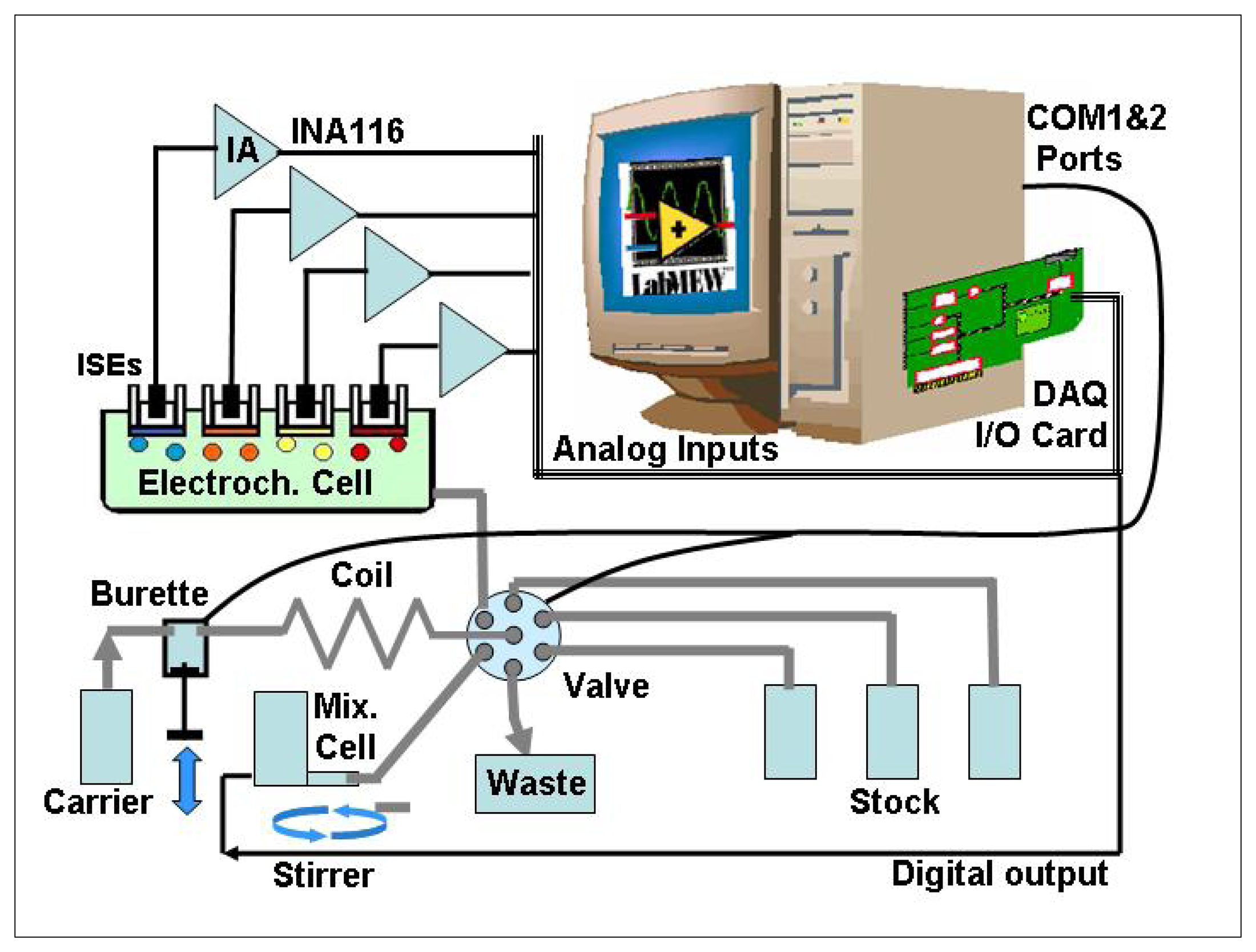
Our design is illustrated in
Figure 1. The use of the SIA technique permits automated operation of the e-tongue for the preparation of mixed analyte standards, the handling of liquid samples and for the data acquisition during their measurement. In this way, the experimental effort involved in the calibration and operation of e-tongues can be clearly facilitated. The developed SIA e-tongue, when adequately controlled and synchronized, can be used for data acquisition of the sensor signals in steady state conditions and during transient sensor response, thus, adding new dimensions in the information used. Finally, the generated data is processed using a properly trained ANN to obtain the sought application.
Different hardware, software, and also processing and programming tools can be applied to e-tongues design [
13]. “Virtual instrumentation” technique allows design of custom-made intelligent PC-based instruments called Virtual Instruments (VIs), which manages the PC hardware and others devices or analytical instruments (i.e DMM, oscilloscopes, pH-meters, multifunction DAQ cards) attached by means of the computer bus, serial, GPIB, parallel, or USB ports, etc. The use of this technique under the graphical LabVIEW development environment is an integrated choice to be considered for the e-tongue design just like a single, easy of use, reliable and expandable instrument [
14].
2. Experimental
2.1 SIA System
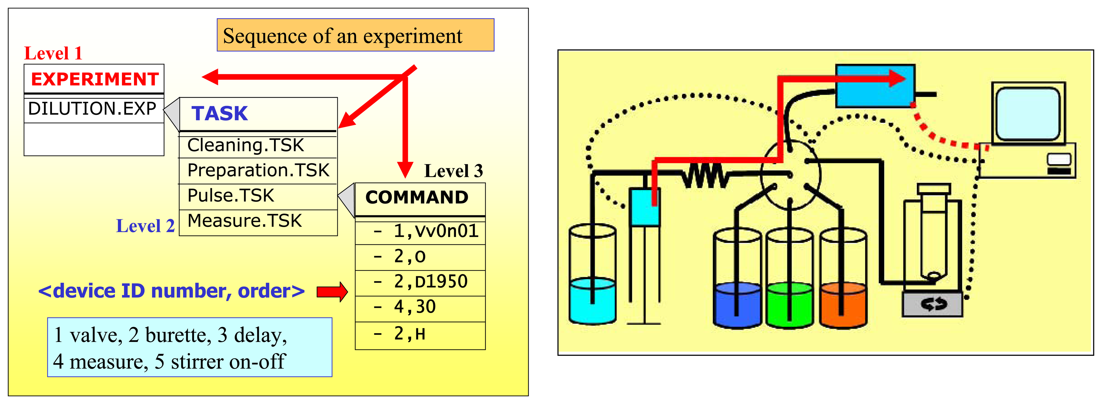
The SIA system (
Figure 2) consists of two main parts, the flow system and the measurement system (i.e. acquisition system). The flow system comprises a PC controlled Crison 2030 microburette (Crison Instruments, Spain) with a 5 ml syringe (Hamilton, Switzerland), a MVP (Hamilton, Switzerland) 6-way multi-port valve (Ref HVXM R36760), a holding coil between the pumping system and the valve, a mixing cell and a PC controlled magnetic stirrer. The microburette assures the accuracy in the management of the standard solutions and diluting carrier. The multi-port valve allows access to the different ports (solutions). A 7 mL methacrylate mixing cell is employed for the homogenisation of the solutions, which are pumped into the sensor array. The PTFE holding coil tube (Bioblock, France) has an internal diameter of 1 mm and its volume is 5 ml. The system combines standards by performing specific dilutions from a number of appropriate stocks, and conveys the mixture to the sensor array.
2.2 Reagents
All chemicals used for the preparation of the solutions were of analytical grade, and deionised water was used throughout. Potassium chloride and calcium chloride were purchased from Fluka (Switzerland). A 0.1 M potassium chloride (Panreac, Barcelona, Spain) solution was used as carrier. All the solutions were freshly prepared prior to use.
Ion-selective electrode (ISE) membranes were prepared dissolving the ionophore, the plasticizer and the polymeric matrix in an organic solvent (Fluka, Switzerland). Two different ionophores for calcium were employed: bis[4-(1,1,3,3-tetramethylbutyl) phenyl] phosphate calcium salt (BTMBPPC) and ETH1001 (both from Fluka, Switzerland). The other ionophores had generic response and were sodium salt of the antibiotic tetronasin (TetronasinNa), provided by the University of Cambridge (UK) [
15], monensin sodium salt (Acros, Belgium) and lasalocid (Fluka, Switzerland). Plasticizers used were dioctyl phenylphosphonate (DOPP), 2-nitrophenyloctylether (o-NPOE) and dibutyl sebacate (DBS) (all from Fluka, Switzerland). The polymeric matrix was poly(vinyl) chloride (PVC) (Fluka, Switzerland) and the volatile solvent was tetrahydrofuran (THF) (Merk, Germany). Potassium tetrakis-4-chlorophenylborate (PTCPB) (Fluka, Switzerland) was used as additive to formulate certain membranes.
Materials used for the preparation of the inner solid contact for the potentiometric sensors were the epoxy resin components Araldite M and HR hardener (Uneco, Barcelona, Spain), and graphite powder (50 μm, BDH Laboratory Supplies, UK) as the conducting filler.
2.3 Control and acquisition system
The measurement system comprised the detection system (sensor array was incorporated into the system in series) and a Ag/AgCl double-junction reference electrode (Orion 900200). Sensors used in the sensor array were were all solid-state, tubular, flow-through electrodes of normal use in our laboratories when working with flow systems [
16].
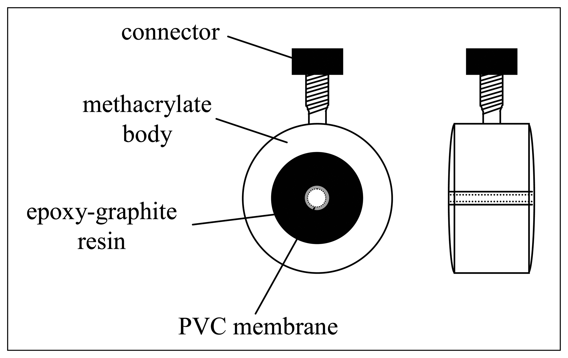
The scheme of the flow-through tubular sensors is sketched in
Figure 3, Their particular design facilitates their placement in series in the flow system. For proper functioning, the inner wall of the axial hole drilled through the inner solid contact is carefully covered with a PVC membrane, which is covering an ohmic solid contact made from a graphite-epoxy resin composite. Once formed, membranes were conditioned in a solution of their primary ion for 24 h. For a proper design of an electronic tongue application, several sensors are needed, and an appropriate selection for the ISE array must be done in order to generate differentiated and cross-term response.
Table 1 summarizes the formulation of the different membranes used in the presented case, which is devoted to alkaline-earth ions. For this reason, membranes with rather selective response to calcium ion plus membranes with generic response to cations have been selected.
Reference and ISE signals are passed to conditioning amplifiers (see
Figure 2) based on the Burr-Brown INA116 instrumentation amplifier, to ensure that minimal current is drawn during voltage measurement. A low-pass filter was used afterwards for each channel to reduce system noise. A solution grounded electrode was added by the application circuit for ion measurement system [
17].
The interface card was a PCL-812PG multifunction I/O DAQ card (Advantech) featuring 16 single–ended gain programmable analog inputs multiplexed to a 12-bit/ 62.5Ksample/sec ADC, and two 16 digital I/O ports. The ADC was triggered by SW via the “measure” command. The system stores voltage samples every 200 ms for each input channel and the obtained voltage value for each measurement corresponds to the mean of 100 acquired samples. The card was interfaced to a 233 MHz Pentium II PC running LabVIEW6.1 under Windows 98. The PC also sends commands to the valve and microburette by RS-232 via COM1&2 ports and to the stirrer (on/off signal) by a digital output line from the multifunction card. The integration of this DAQ card in the LabVIEW environment is accomplished by means of specific drivers made available by the manufacturer.
2.4 Software
The programmed VI commands the whole system (valve, microburette, DAQ card and stirrer). The main program executes a sequence structure which depending on the decoded command, sends appropriate orders to a particular device (each one has an ID number) of the system. For the serial port communications, VISA (Virtual Instrument Standard Architecture) sub-VIs from the LabVIEW libraries were employed. Another sub-VIs from Advantech library were used for handling the DAQ Card (SW trigger multichannel acquisition and digital output). The SW operation is based on reading and decoding user-programmed ASCII text files containing the commands instructions into three hierarchical levels:
First Level: Experiments: Tasks for complete a job, i.e. preparing and measuring dilutions from the stocks during a calibration process.
Second Level: Tasks: Instructions comprising commands to carry out basic or unitary tasks (system set-up, cleaning the system, preparing a single dilution).
Third Level: Commands: Low-level orders sent to the devices (voltage measure, stirrer on/off, delay, open/close valve, etc) which form a specific second level task. Each order is preceded by the device ID number followed by a comma <n, order>. In this syntax, n refers to the controlled device in the SIA set-up, 1 for the valve, 2 for the burette, 3 for a wait delay, 4 for data acquisition and 5 for the stirrer. Specific orders for the valve and burette are exactly those given by the manufacturers of each device. The rest of options just indicate the time to remain activated.
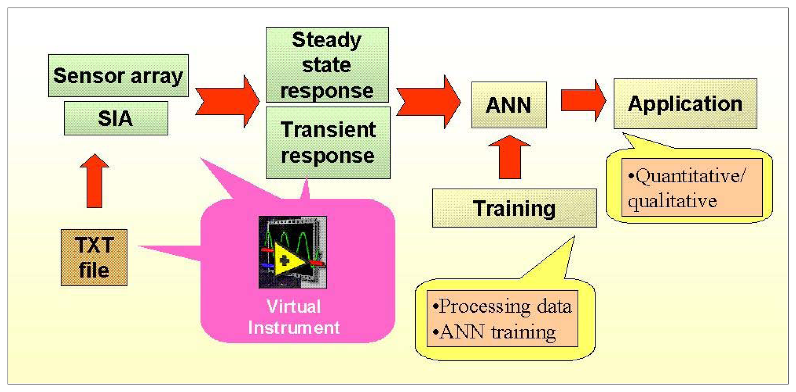
The scheme of a running experiment is showed in
Figure 4. In this example, the system prepares a dilution from the stock solutions, conveys it to the sensor array in a liquid pulse and acquires the potentials from the array as a transient matrix.
The final information is processed employing an ANN. The programming and operation of ANN models is to be performed in a separate, subsequent stage, by specific code written in MATLAB 6.5 environment.
3. Results and discussion
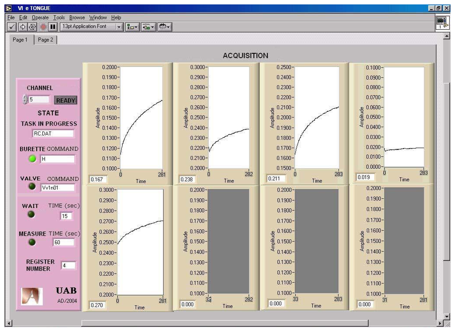
The front panel of the VI is divided in two sections (
Figure 5). On the right side, the experimental data from each sensor is graphically displayed. On the left side, the instrument includes a “READY” button and a group of LEDs and string indicators that show the task and command currently on execution. It also displays the file name of the last recording stored. For each measurement, the data collected and the time stamp are stored in spreadsheet file format and are easily exported to other Windows applications like Notepad, EXCEL or SIGMAPLOT.
In order to test the system, two procedures were followed. The first one was related to the accuracy of the acquisition system and the second one was related to the reproducibility when preparing liquid samples.
Potentiometric direct calibrations and transient recordings were performed using the system for measuring different automatically prepared dilutions.
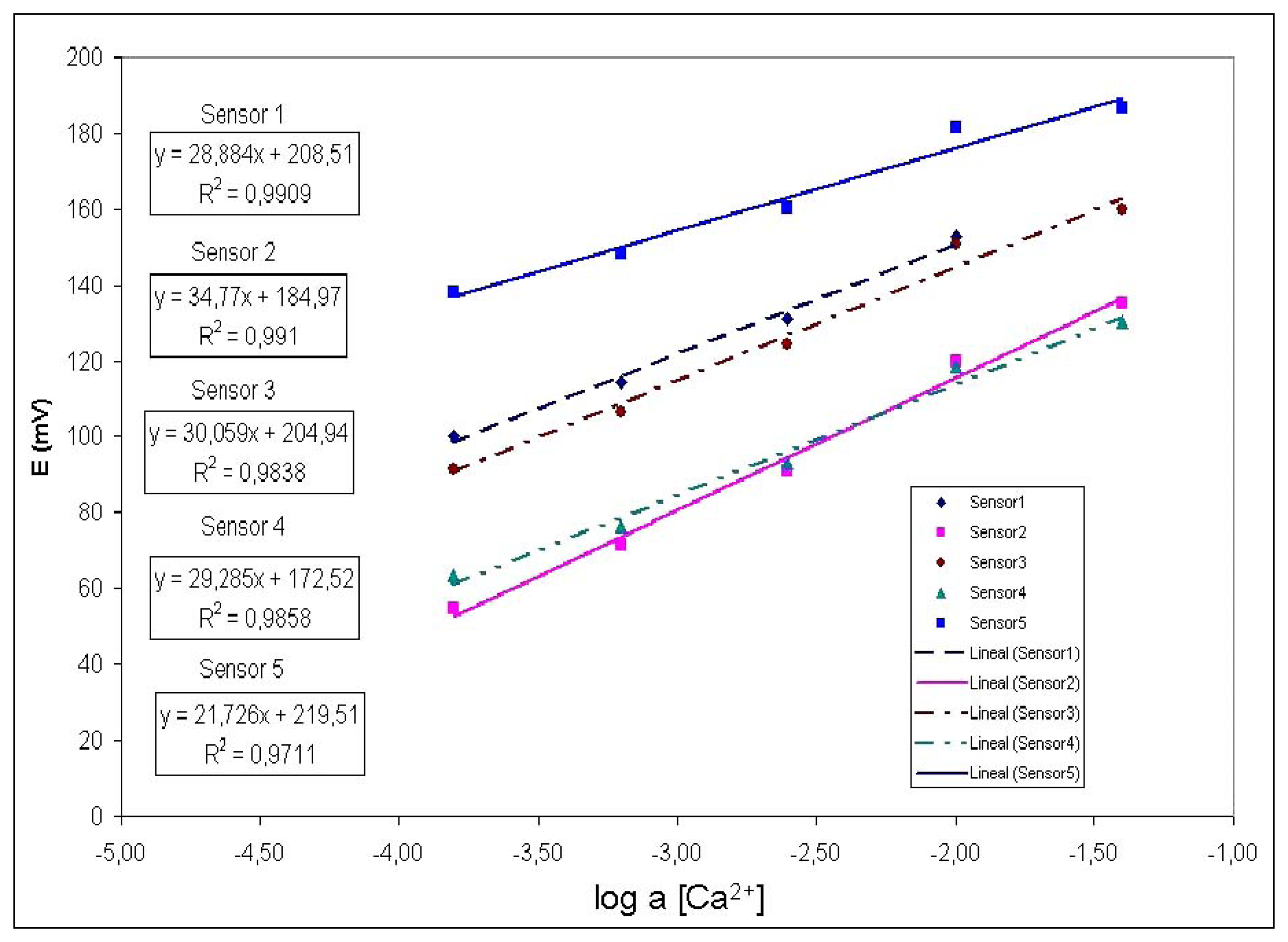
Figure 6 shows an example of a calibration run using the five electrodes prepared versus different solutions automatically prepared diluting a calcium ion mother solution. For each one the calibration was performed according to Nernst.
In order to extract some validation data of the functioning of the system, the information on
figure 5 is processed by separating the experimental points in two groups: one group for calibrating the system (regression) and the other group for validating the procedure, by computing the resulting error in a leave-k-out scheme. The results are presented in the
Table 2, which shows the interpolation error for each sensor, corresponding to 2 standards solutions of different concentration. Observe that the limited errors are below 6%.
To check the reproducibility of the system, an arbitrary 2mM calcium standard was prepared in the laboratory, and the same concentration was asked to the system to be prepared from the stock solution. After interpolation in a recent calibration, deviations from the expected value were lower than 5% in both cases, varying on the individual sensor considered. Repetitivity of the SIA system was estimated from 10 replicated dilutions and measurements of the 2mM sample, this one prepared manually and introduced in the system for being presented 10 times to the sensors. For the automatically prepared sample, repetitivity ranged from 1.1-4.2% RSD depending on the sensor, while the repeated measurement of the manually prepared sample showed an interval between 1.8-5.3% RSD. As observed, the precision on the preparation and operation is a main feature of the developed system.
More interestingly, as a second experimental possibility, the system is capable of acquiring the transient response after the introduction of a sample plug (step response).
Figure 7 illustrates a transient recording obtained after the introduction of different Ca
2+ solutions in a step response experiment, starting from the background electrolyte until the specified concentration level.
The recording corresponds to a calcium ion selective electrode, which employs the neutral carrier ETH1001 (Fluka, Switzerland) as the electroactive element in the potentiometric membrane. The processing of the dynamic information contained in the transient response will add a further dimension in the complexity of the processed information, which will improve the ability of the e-tongue to discriminate species in a sample. This concept has been scarcely used in the field of potentiometric e-tongues, although it is of common use in the field of e-noses. This strategy has clear advantages, as an additional dimension of the response is added. In this way, the representation ability of the ANN model is improved with the kinetic features of the response, which can be an aid to solve the more difficult cases. Certain contributions in the chemical literature are precursors of this idea, as the work with biosensor response employing FIA [
18].
4. Conclusions
An electronic tongue based on potentiometric sensors and Sequential Injection Analysis (SIA) with a Virtual Instrument implemented in LabVIEW6.1™ has been developed and successfully tested. The functioning of the system has been improved using a virtual instrument, which just manages text instruction files, previously programmed by the user in order to command the whole system. These instructions can be reutilised in other different experiments.
Using this automated approach, the time needed for the generation of the training information of an electronic tongue employing potentiometric sensors can be reduced from weeks to hours, with an added improvement of reproducibility and ease of use.
A further advantage is that an additional dimension can be gained to the departure information, the kinetic profile or transient recorded for the sensors after the arrival of the sample that can be used to differentiate better the studied cases. The development of another independent processing VI is now in progress, which performs data compression necessary for training the ANN, where the significant features from the transient response will be extracted by the use of the Fourier or Wavelet transforms.


