Fiber Ring Laser Directional Torsion Sensor with Ultra-Wide Linear Response


1
College of Electronics Engineering, Heilongjiang University, Harbin 150080, China
2
School of Electronic Information and Electrical Engineering, Chongqing University of Arts and Sciences, Chongqing 402160, China
*
Authors to whom correspondence should be addressed.
Sensors 2019, 19(16), 3613; https://doi.org/10.3390/s19163613
Submission received: 22 July 2019
/
Revised: 9 August 2019
/
Accepted: 16 August 2019
/
Published: 20 August 2019
(This article belongs to the Section Optical Sensors)
Abstract
:In this paper, a comprehensive passive torsion measurement is performed firstly in a 40-cm-long polarization maintaining fiber-based Sagnac interferometer (PMF-SI), and the non-linear torsion response is found and investigated. Then, a fiber laser torsion sensor (FLTS) with a dual-ring-cavity structure is proposed and experimentally demonstrated, in which the PMF-SI is utilized as the optical filter as well as the sensing unit. In particular, the highly sensitive linear range is adjusted through fine phase modulation, and owing to the flat-top feature of fringes, an ~83.6% sensitivity difference is effectively compressed by the generated lasing. The experimental results show that, without any pre-twisting, the ultra-wide linear response from –175 to 175 rad/m is gained, and the torsion sensitivities are 2.46 and 1.55 nm/rad with high linearity (>0.99) in the clockwise and anti-clockwise directions, respectively. Additionally, a high extinction ratio (>42 dB) and small line-width (~0.14 nm) are obtained in the proposed FLTS, and the corresponding detection limit reaches 0.015 rad/m.
1. Introduction
To date, fiber torsion sensors have played indispensable roles in aerospace engineering, artificial intelligence, and industrial automation due to the merits of their compact size, high sensitivity, low cost, and immunity to electromagnetic interference. Lots of schemes have been demonstrated based on fiber gratings [1,2,3,4,5,6], modal interferometers [7,8,9,10], Sagnac interferometers (SI) [11,12,13,14,15,16,17,18], microfibers [19,20], and multi-/hollow-core fibers [21,22,23]. Among them, polarization-maintaining fiber (PMF) based Sagnac-loop structures are viewed as one of the most practical torsion sensors owing to their stability and cost-efficiency. To enhance sensitivity, the etched and heated PMFs were respectively adopted in [14,16], and the maximum sensitivity reached 18.60 nm/(rad/m). Furthermore, Huang reported a low-birefringence single-mode fiber (SMF) based SI and the highest sensitivity of up to 3.25nm/° was exhibited in the range from −10 to 80 degrees [17]. Nevertheless, it is worth noting that most SI-based torsion sensors show non-linear responses to the varied torsion, typically a sine- or sinc-function [12,17,18,24]. That means that pre-twisting is usually necessary for direction discrimination. In addition, for the passive schemes, a common issue is that the detection limit of sensors is constrained by the low visibility and large line-width (LW) of fringes.
Alternatively, fiber laser sensors (FLS) with a high extinction ratio (ER) and small LW have received much attention as an effective method for improving detection limits. Additionally, FLS-based schemes have been continuously applied in the sensing of temperature, refractive index (RI), strain, and curvature [25,26,27,28,29,30,31,32]. Recently, Shi et al. reported a fiber ring laser for torsion sensing using cascaded helical long-period gratings (HLPG), and an ultra-wide linear response of torsion from −100 to 100 rad/m was presented but with a sensitivity of 0.084 nm/(rad/m) [33]. Díaz et al. demonstrated a distributed Bragg reflector laser torsion sensor based on frequency modulation [34].
In this paper, a novel dual-ring-cavity-based FLS for directional torsion measurement is proposed and experimentally demonstrated, in which a PMF-based Sagnac loop structure is utilized as an optical filter as well as the sensing unit. Moreover, owing to the flat-top feature of fringes, an ~83.6% sensitivity difference is effectively reduced by the generated lasing. Therefore, under fine phase modulation, an ultra-wide linear response from −175 to 175 rad/m is gained with a linearity of 0.991. Additionally, the torsion sensitivities reach 2.46 and 1.55 nm/rad in the clockwise (CW) and anti-clockwise (ACW) directions, respectively. Additionally, the proposed FLTS has an ER of >42 dB and an LW of ~0.14 nm, and the corresponding detection limit reaches 0.015 rad/m. In addition, the proposed FLTS is ease of fabrication, cost-efficiency, and has the potential for application in structural health monitoring and industrial automation.
2. Principles
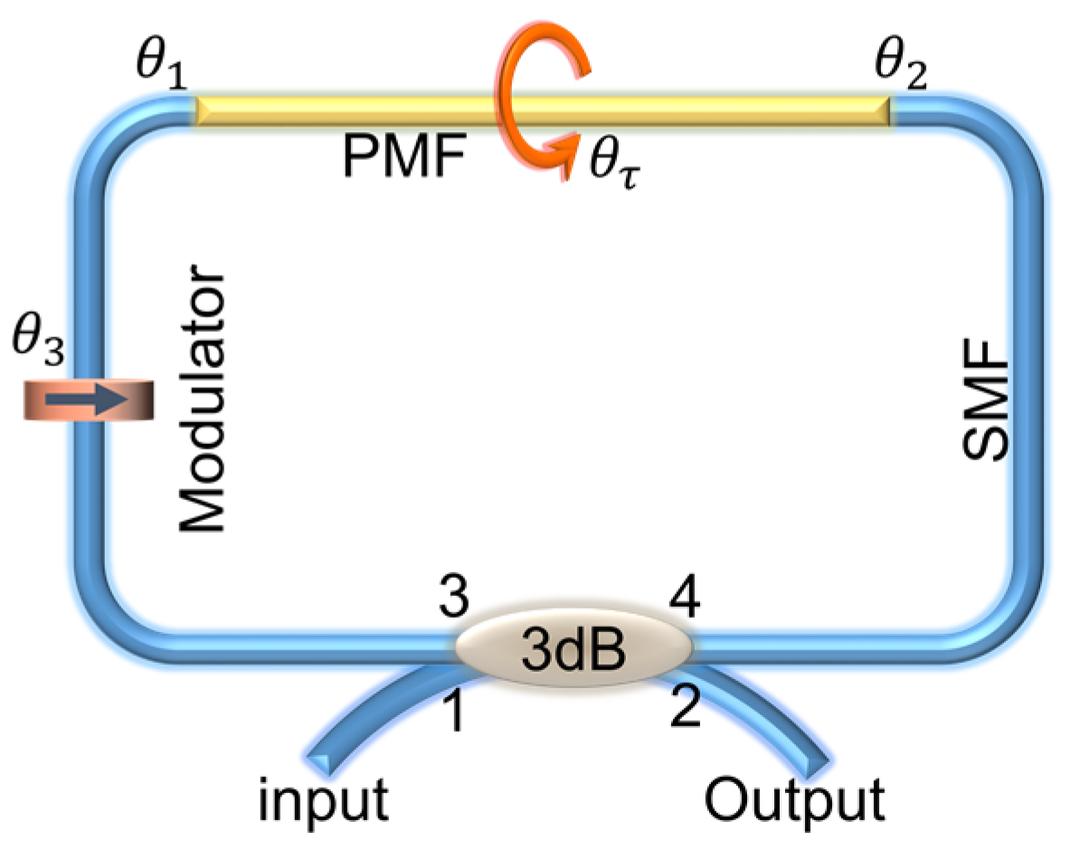
In a Sagnac loop, as shown in Figure 1, the input light is equally split into two propagation beams and re-combined through a 3 dB coupler, which corresponds to the orthogonal polarization modes and propagating along the fast and slow axes of PMF. Therefore, a stable interference will be formed because of the refractive index (RI) difference between and . Furthermore, we define and respectively, as denoting the angles between the light at the spliced point and the fast axis of PMF, and symbolizes the phase shift caused by a modulator.
According to [35], when ignoring the insertion loss, the transmission spectrum of PMF-SI is derived as
where is the phase difference caused by and , and it can be written as
where λ is the wavelength of incident light, L is the length of the PMF, and are the RI of the PMF fast and slow axes, and . For the given angles of , and , Equation (1) can be simplified as
When (m is an integer), the resonance wavelength will be
and the free spectrum range (FSR) is approximately written as
Further, when the PMF is twisted, its effective RI change caused by shear strain will be expressed as
where and are the photo-elastic coefficients of the fast and slow axes, respectively. τ = θτ /l is the twist rate, where is the twist angle and l is the length of twisted fiber. Assuming , the phase change will be written as
Neglecting the effect of longitudinal strain (), Equation (7) is changed to . Combined with Equation (2), the wavelength shift can be derived as
Equation (8) shows that is merely proportional to for a given L, and the torsion direction can be recognized by the red- or blue-shift of . However, due to the varied and under the added shear strain, the value of is usually a non-linear response to the applied torsion. This means a PMF-SI based torsion sensor may be only effective in a small range and needs a pre-twisting angle to assist direction discrimination. Our work then focuses on enlarging the linear response region of torsion under the non-pre-twisting state.
3. Experiments and Results
As shown in Figure 2a, the Sagnac loop structure was mainly formed by a 40 cm long PMF (CETC, PM1550-1-06002-3) and a 3 dB SMF-coupler. The input and output ports of the coupler respectively connected with a broadband light source (BBS, homemade, operated in the range of 1525–1565 nm) and an optical spectrum analyzer (OSA, Agilent 86142B, with a resolution of 0.01 nm). The PMF was straightly fixed on the fiber holder and rotator with a small axial stress in order to reduce the fiber bending effect. A polarization controller (PC) was used as a modulator to introduce the matched phase change. Additionally, the distance between two holders was fixed at ~30 mm in order to get a large torsion range. Figure 2b shows the transmission spectra of the BBS (red-line) and PMF-SI (blue-line). The BBS had a flat spectrum with fluctuations of less than 1.9 dB across the whole 40 nm bandwidth, and the three formed fringes were located at 1530.4, 1544.6, and 1558.92 nm. Moreover, the average visibility reached about 25.6 dB with approximately the same FSR (~14.3 nm).
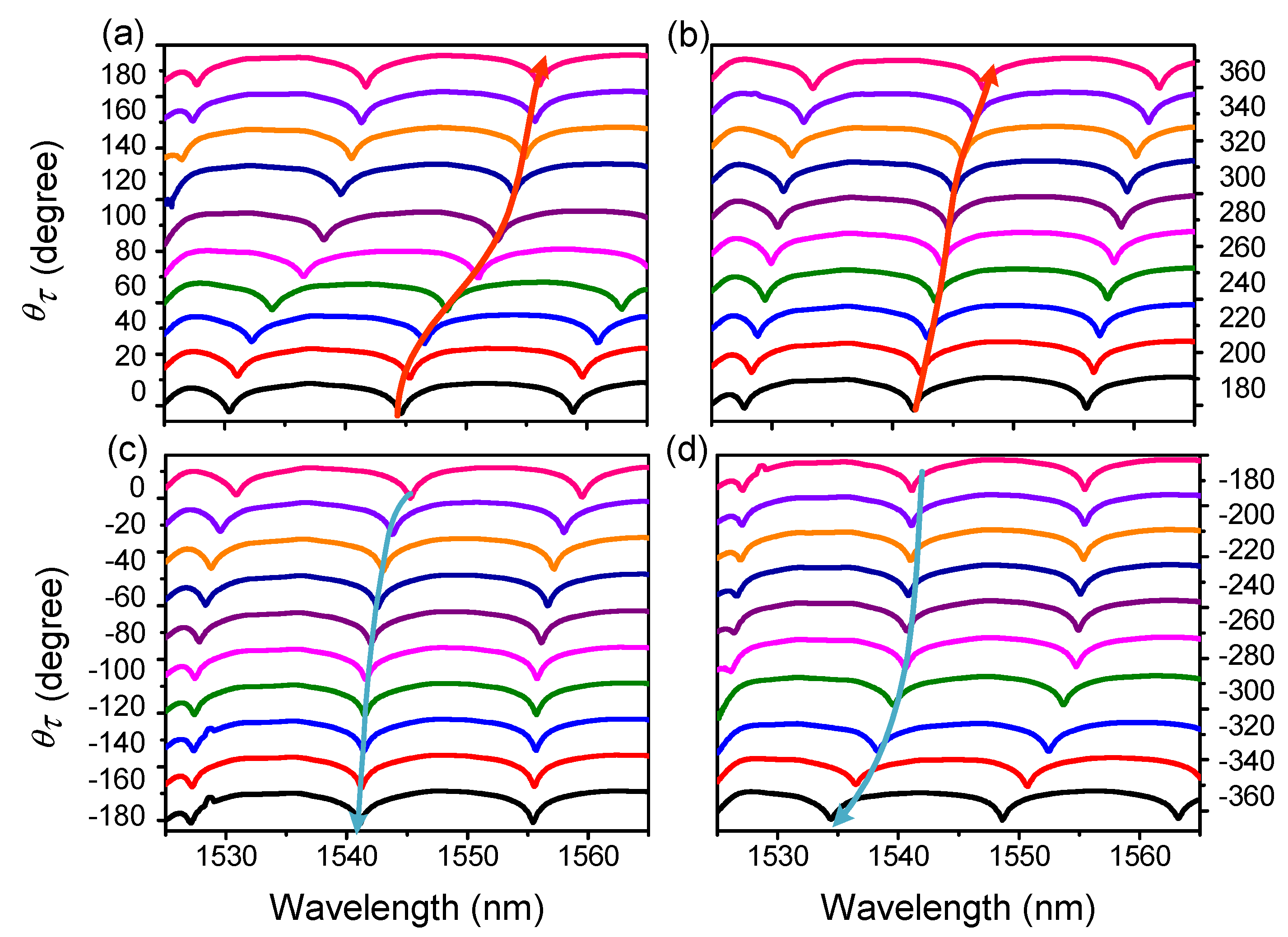
Comprehensive torsion measurements were then performed with the varied in the range from −360° to 360° with an interval of 20°. According to Figure 3a,b, it is clear that the wavelength red-shifted in the CW direction from 0° to 360°, but blue-shifted in the ACW direction from 0° to −360°, as shown in Figure 3c,d. Nevertheless, we also noticed that this wavelength shift was non-linear. Figure 4 shows the torsion response in the CW (from −360° to 360°) and ACW (from 360° to −360°) directions, and the quasi-periodic feature of wavelength shift is exhibited with the added .
For clarity, the sensitive and insensitive regions in Figure 4a,b were divided into four parts, denoted by C-i and AC-i (i = 1~4), respectively. In more detail, as shown in Figure 4a, the highly sensitive regions were located at C-1(approximately –360° to –260°) and C-3 (0°~120°) with sensitivities of 102 and 55 pm/°. However, the sensitivities were merely ~9.3 and 31.2 pm/° in their neighboring regions C-2 (approximately –260° to 0°) and C4 (120°~360°). These results mean that the PMF-SI is only sensitive to the varied torsion in a small range (100°~120°). Moreover, the maximum sensitivity difference (SD) at around 0° reached 92.7 pm/°, and the minimum value between C-1/C-3 and C-2/C-4 was ~22 pm/°. Similar results were also observed in the ACW direction and are presented in Figure 4b. By calculation, the maximum SD (between AC-2 and AC-3) was found to be 91.1 pm/°, and the minimum SD (between AC-1/AC-3 and AC-2/AC-4) was 21 pm/°. Such high SD values indicate that a pre-twisting angle may be necessary to complete an effective directional torsion measurement.
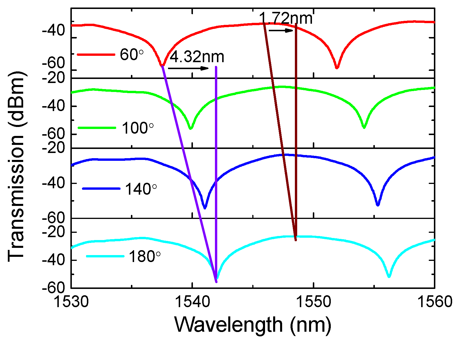
Equation (1) shows that the transmission spectrum of PMF-SI can be adjusted by . A numerical simulation was conducted to reveal the relation between and . As shown in Figure 5a, the interference fringes red-shifted with the varied in the range from 0 to . Additionally, Figure 5b shows that linearly increased with the added and the coefficient was 0.0692 nm/°. In [36], it was shown that can be adjusted and implemented by an external modulator, such as a PC. Additionally, the wavelength-shift difference between the dips and peaks of fringes was investigated. As shown in Figure 6, the dip-shift was about 4.32 nm but the peak merely shifted by 1.72 nm when = 60°~180°. This flat-top feature means that the high SD presented in Figure 4 will be greatly reduced and homogenized when the peaks of fringes are utilized. Additionally, the linear response range will definitely be enlarged although a ~60% reduction in torsion sensitivity will occur.
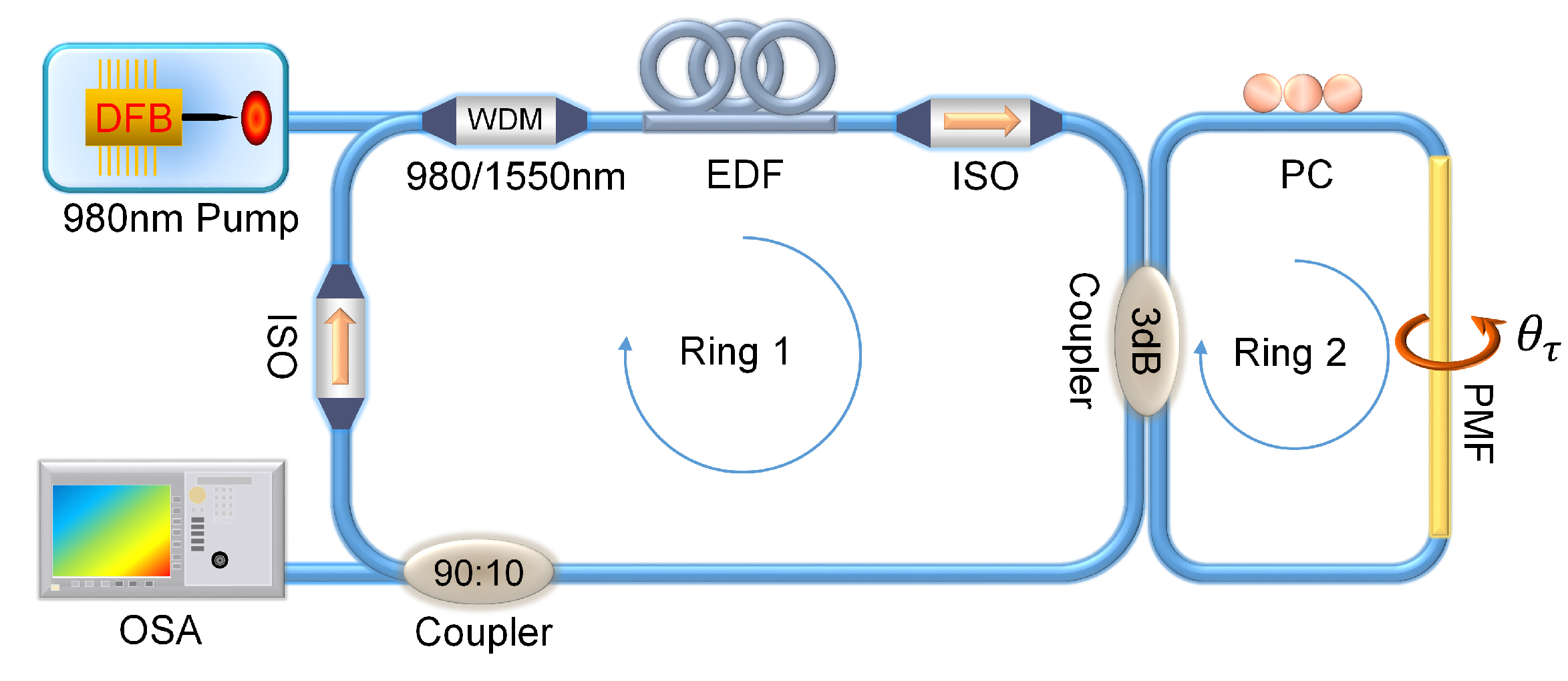
The above analysis indicates that a torsion sensor with an ultra-wide linear response can be achieved by combining a fiber ring laser (FRL) and a well-phase-modulated Sagnac-loop. The experimental setup of fiber laser torsion sensor (FLTS) with a dual-ring-cavity structure is shown in Figure 7, where the Sagnac loop (denoted by Ring-2) as an optical filter as well as the sensing unit is connected with the FRL (denoted by Ring-1) by a 3 dB coupler. In Ring-1, a laser diode (LD, Oclaro LC96HH74P-20R) with a central wavelength of 976 nm is used as the pump source. Through a 980/1550 nm wavelength division multiplexer, a 10 m long erbium-doped fiber (EDF, Nufern EDFC-980-HP) was stimulated by amplified spontaneous emission. Then, the generated broadband light with the band of 1525–1565 nm was equally split into Ring-2.
By fine adjustment of the PC, the output from the Sagnac-loop was stably operated in Ring-1 and the formed lasing was finally monitored and recorded by OSA. In particular, two isolators were used to prevent the effects of reflection and spatial hole-burning. Figure 8a shows the output spectra of FRL under varied pump current (denoted by IP) in the range of 80~200 mA. Clearly, with the rise of IP, the output intensity of lasing continuously increased and the maximum intensity located at 1566.13 nm reached −18.23 dBm when IP = 200 mA. Furthermore, the relationship between the ER/LW of lasing and IP was investigated. Figure 8b shows an obvious rise in ER (~15.04 dB) when IP increased from 80 to 100 mA. However, the rise greatly decreased in the range of 100~200 mA to merely ~4.74 dB. Similarly, Figure 8c shows that the LWs of lasing quickly decreased from 0.19 to 0.14 nm when IP increased from 80 to 140 mA. However, the LW values were maintained at ~0.14 nm when IP > 140 mA. Considering the stability of FRL, IP = 160 mA was selected and the corresponding LW and ER of lasing were 0.14 nm and 42.18 dB, respectively.
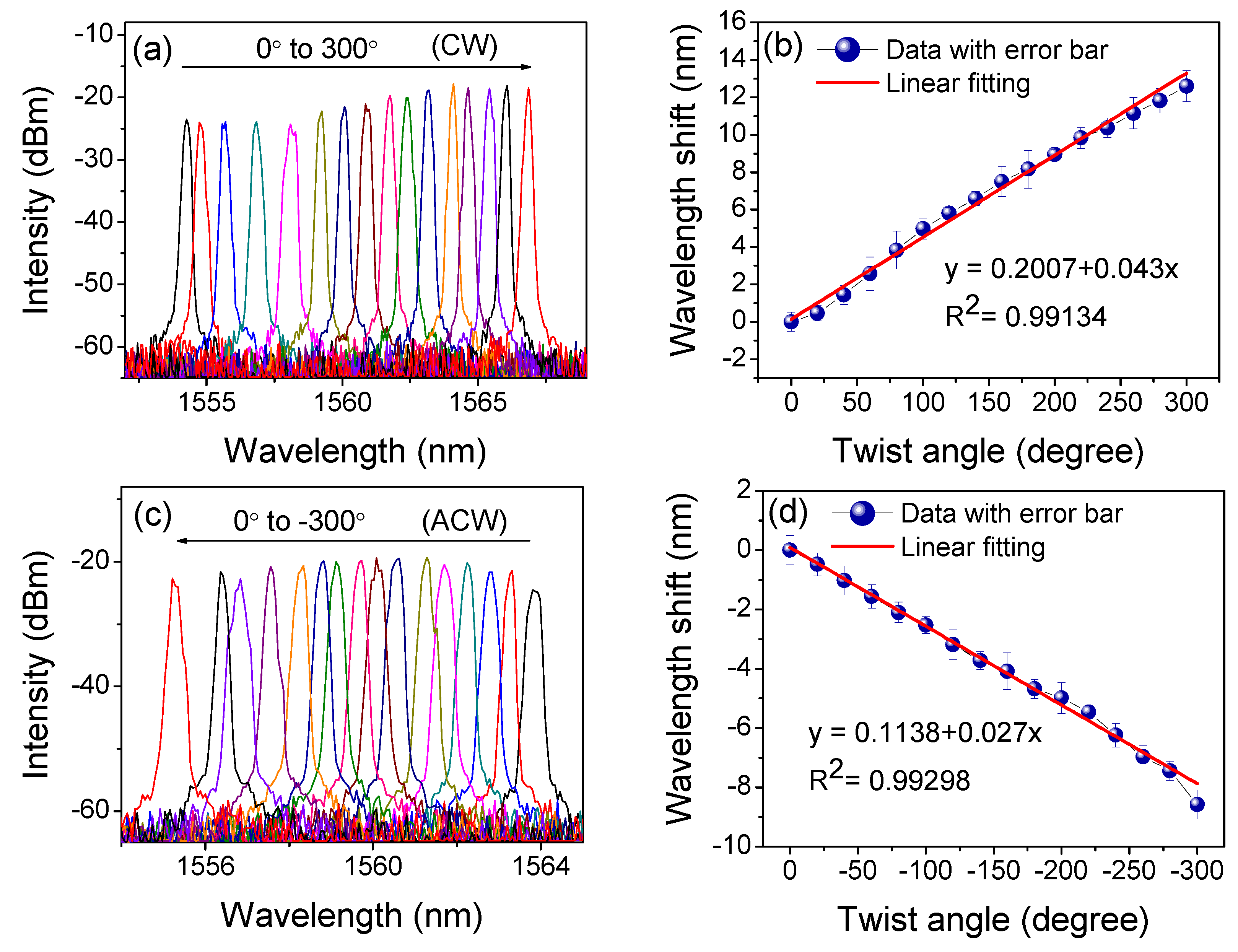
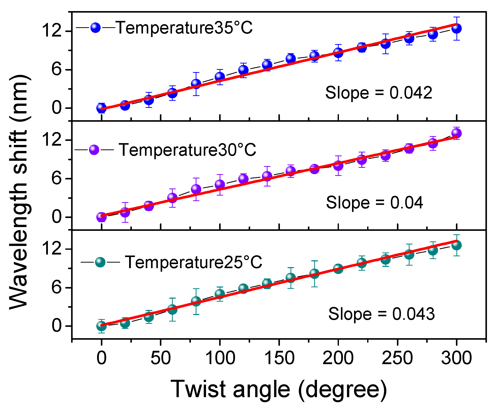
We then set IP = 160 mA and twisted the PMF with the varied . As shown in Figure 9a, the emitted lasing red-shifted by about 12.4 nm in the CW direction with a fluctuation of 6.57 dB. Additionally, the relationship between and is shown in Figure 9b. Compared to the results in Figure 4a, the SD was obviously compressed in the range from 0° to 300° (which corresponds to the range of 0~175 rad/m). Thus, the calculated torsion sensitivity reached 2.46 nm/rad (43 pm/°) with a linearity of 0.991. Similar results in the ACW direction are demonstrated in Figure 9c,d but with a blue-shift in wavelength. By calculation, the torsion sensitivity in ACW direction was determined to be 1.55 nm/rad (27 pm/°) with a linearity of 0.993 in the range from 0° to −300° (which corresponds to the range of approximately 0 to −175 rad/m). Compared to the results shown in Figure 4, the sensitivity in FLTS was reduced by about 57% in the CW direction and 63.5% in the ACW direction, respectively. However, the SD was also reduced by ~82.6% (=) across the whole range of −300° to 300°. We then measured the repeatability of our FLTS at different temperatures, and the corresponding relationships between the wavelength and twist angle are given in Figure 10. According to the measured results, similar torsion sensitivities (~0.04 nm/°) were presented in the range from 0° to 300°. So, the maximum SD at different temperatures was restrained within 0.003 nm/°. This tiny value of SD indicates that our sensor has a stable wavelength response in torsion with a varied ambient temperature.
A comparison between our work and other related torsion sensors is given in Table 1. It is obvious that the largest linear range, ±300° (±175 rad/m), was obtained with our proposed FLTS, which is an improvement of 2.5~10 times compared with the listed passive schemes. It is worth noting that, as mentioned above, this wide linear range was gained with a more than 50% reduction in sensitivity. Fortunately, according to Equation (8), the torsion sensitivity of FLTS can be enhanced by simply reducing the length of the PMF.
Furthermore, the detection limit of FLTS is defined by
where S is the torsion sensitivity and R is the detection resolution. From [30], R can be expressed as
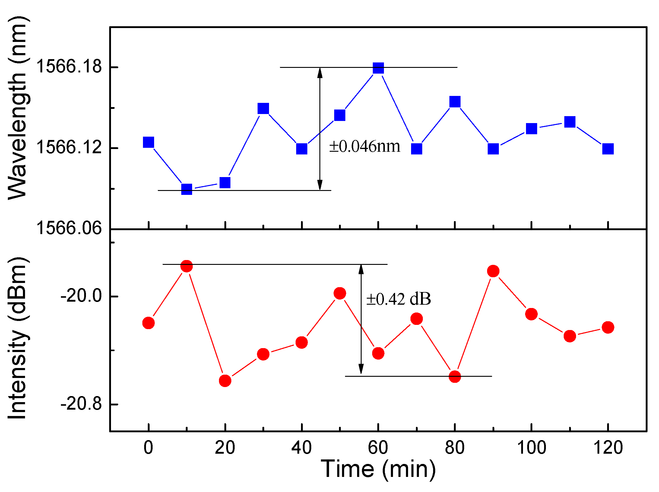
where , and respectively, denote the errors caused by amplitude noise, thermal variation, and spectral resolution. In general, is small enough to be ignored at room temperature and , where is the wavelength resolution of OSA. is the main noise and is dependent on the values of LW and ER. In our sensor, the calculated was equal to 1.25 × 10⁻² nm and was 2.89 × 10⁻³ when the parameters LW = 0.14 nm, ER = 42.18 dB, and = 0.01 nm were adopted. The corresponding resolution was 0.0376 nm and the DL of FLTS reached 0.015 rad/m. In addition, a stability test of the output lasing was performed with respect to the wavelength and intensity when Ip =160 mA and the room temperature was kept at 25 ± 0.2 ℃. Figure 11 shows that within 2 hours, the wavelength and intensity fluctuations of FLTS were constrained within ±0.046 nm and ±0.42 dB, respectively.
4. Conclusions
In this paper, the flat-top feature of the fringes of PMF-SI was investigated and a novel dual-ring-cavity based FLTS was proposed and completed in order to reduce the non-linear response of torsion. Through fine phase modulation, the torsion response curve shifted and homogenized in the FLTS. The experimental results showed that the sensitivity difference was effectively compressed and an ultra-wide linear response from −175 to 175 rad/m was gained. Moreover, the acceptable torsion sensitivities were 2.46 and 1.55 nm/rad with a linearity of 0.99 in the CW and ACW directions, respectively. The corresponding detection limit reached 0.015 rad/m owing to the high ER and small LW. Additionally, the wavelength and intensity fluctuations of FLTS were limited to ±0.09 nm and ±0.42 dB within 2 hours. The proposed FLTS is stable, practical, and very promising for the applications of structural health monitoring and industrial monitoring.
Author Contributions
J.Y. and X.D. conceived and designed the experiments; X.L., F.W. and X.Z. performed the experiments; X.L. analyzed the data; J.Y. and X.L. wrote the paper.
Funding
This work is supported by National Natural Science Foundations of China under Grants (61675066, 61302075); Natural Science Foundations of Heilongjiang Province under Grant (QC2015068).
Conflicts of Interest
The authors declare no conflict of interest.
References
- Deng, M.; Xu, J.; Zhang, Z.; Bai, Z.; Liu, S.; Wang, Y.; Zhang, Y.; Liao, C.; Jin, W.; Peng, G.; et al. Long period fiber grating based on periodically screw-type distortions for torsion sensing. Opt. Express 2017, 25, 14308–14316. [Google Scholar] [CrossRef] [PubMed]
- Xian, L.; Wang, P.; Li, H. Power-interrogated and simultaneous measurement of temperature and torsion using paired helical long-period fiber gratings with opposite helicities. Opt. Express 2014, 22, 20260–20267. [Google Scholar] [CrossRef] [PubMed]
- Tian, X.G.; Tao, X.M. Torsion measurement using fiber Bragg grating sensors. Expr. Mech. 2001, 41, 248–253. [Google Scholar] [CrossRef]
- Zhang, X.; Chen, J.; González-Vila, Á.; Liu, F.; Liu, Y.; Li, K.; Guo, T. Twist sensor based on surface plasmon resonance excitation using two spectral combs in one tilted fiber Bragg grating. J. Opt. Soc. Am. B 2019, 36, 1176–1182. [Google Scholar] [CrossRef]
- Shen, C.; Zhang, Y.; Zhou, W.; Albert, J. Au-coated tilted fiber Bragg grating twist sensor based on surface plasmon resonance. Appl. Phys. Lett. 2014, 104, 071106. [Google Scholar] [CrossRef] [Green Version]
- Yiping, W.; Wang, M.; Huang, X. In fiber Bragg grating twist sensor based on analysis of polarization dependent loss. Opt. Express 2013, 21, 11913–11920. [Google Scholar] [CrossRef] [PubMed]
- Huerta-Mascotte, E.; Sierra-Hernandez, J.M.; Mata-Chavez, R.I.; Jauregui-Vazquez, D.; Castillo-Guzman, A.; Estudillo-Ayala, J.M.; Guzman-Chavez, A.D.; Rojas-Laguna, R. A Core-Offset Mach Zehnder Interferometer Based on A Non-Zero Dispersion-Shifted Fiber and Its Torsion Sensing Application. Sensors 2016, 16, 856. [Google Scholar] [CrossRef] [PubMed]
- Dong, Y.; Sun, C.; Xiao, H.; Dong, C.; Jian, S. Twist and temperature characteristics of the PD-NSN fiber structure based on in-line Mach-Zehnder interferometer. Opt. Fiber Technol. 2017, 33, 39–44. [Google Scholar] [CrossRef]
- Fu, Q.; Zhang, J.; Liang, C.; Ikechukwu, I.P.; Yin, G.; Lu, L.; Shao, Y.; Liu, L.; Liu, D.; Zhu, T. Intensity-modulated directional torsion sensor based on in-line optical fiber Mach–Zehnder interferometer. Opt. Lett. 2018, 43, 2414–2417. [Google Scholar] [CrossRef]
- Song, B.; Miao, Y.; Lin, W.; Zhang, H.; Wu, J.; Liu, B. Multi-mode interferometer-based twist sensor with low temperature sensitivity employing square coreless fibers. Opt. Express 2013, 21, 26806–26811. [Google Scholar] [CrossRef] [PubMed]
- Chen, W.; Lou, S.; Wang, L.; Zou, H.; Lu, W.; Jian, S. Highly Sensitive Torsion Sensor Based on Sagnac Interferometer Using Side-Leakage Photonic Crystal Fiber. IEEE Photonics Technol. Lett. 2011, 23, 1639–1641. [Google Scholar] [CrossRef]
- Zu, P.; Chan, C.C.; Jin, Y.; Gong, T.; Zhang, Y.; Chen, L.H.; Dong, X. A Temperature-Insensitive Twist Sensor by Using Low-Birefringence Photonic-Crystal-Fiber-Based Sagnac Interferometer. IEEE Photonics Technol. Lett. 2011, 23, 920–922. [Google Scholar] [CrossRef] [Green Version]
- Kim, H.; Kim, T.; Kim, B.; Chung, Y. Temperature-Insensitive Torsion Sensor With Enhanced Sensitivity by Use of a Highly Birefringent Photonic Crystal Fiber. IEEE Photonics Technol. Lett. 2010, 22, 1539–1541. [Google Scholar] [CrossRef]
- Song, B.; Zhang, H.; Miao, Y.; Lin, W.; Wu, J.; Liu, H.; Yan, D.; Liu, B. Highly sensitive twist sensor employing Sagnac interferometer based on PM-elliptical core fibers. Opt. Express 2015, 23, 15372–15379. [Google Scholar] [CrossRef]
- Shao, L.; Zhang, X.; He, H.; Zhang, Z.; Zou, X.; Luo, B.; Pan, W.; Yan, L. Optical Fiber Temperature and Torsion Sensor Based on Lyot-Sagnac Interferometer. Sensors 2016, 16, 1774. [Google Scholar] [CrossRef]
- Wu, J.; Shen, X.; Luo, X.; Hu, X.; Peng, J.; Yang, L.; Li, J.; Dai, N. Temperature-insensitive torsion sensor with sensitivity-enhanced by processing a polarization-maintaining photonic crystal fiber. Opt. Commun. 2017, 401, 80–84. [Google Scholar] [CrossRef]
- Huang, B.; Shu, X. Highly sensitive torsion sensor with femtosecond laser-induced low birefringence single-mode fiber based Sagnac interferometer. Opt. Express 2018, 26, 4563–4571. [Google Scholar] [CrossRef]
- Silva, R.M.; Ferreira, M.S.; Frazão, O. Temperature independent torsion sensor using a high-birefringent Sagnac loop interferometer. Opt. Commun. 2012, 285, 1167–1170. [Google Scholar] [CrossRef]
- Qian, Y.; Sun, B.; Wan, H.; Zhang, Z. Novel temperature-independent microfiber sensor fabricated with the tapering-twisting-tapering technique. Appl. Opt. 2019, 58, 3091–3096. [Google Scholar] [CrossRef]
- Chen, Y.; Semenova, Y.; Farrell, G.; Xu, F.; Lu, Y. A Compact Sagnac Loop Based on a Microfiber Coupler for Twist Sensing. IEEE Photonics Technol. Lett. 2015, 27, 2579–2582. [Google Scholar] [CrossRef]
- Liu, C.; Jiang, Y.; Du, B.; Wang, T.; Feng, D.; Jiang, B.; Yang, D. Strain-insensitive twist and temperature sensor based on seven-core fiber. Sens. Actuators A Phys. 2019, 290, 172–176. [Google Scholar] [CrossRef]
- Tan, F.; Liu, Z.; Tu, J.; Yu, C.; Lu, C.; Tam, H.-Y. Torsion sensor based on inter-core mode coupling in seven-core fiber. Opt. Express 2018, 26, 19835–19844. [Google Scholar] [CrossRef]
- Liu, D.; Kumar, R.; Wei, F.; Han, W.; Mallik, A.K.; Yuan, J.; Yu, C.; Kang, Z.; Li, F.; Liu, Z.; et al. Highly Sensitive Twist Sensor Based on Partially Silver Coated Hollow Core Fiber Structure. J. Lightwave Technol. 2018, 36, 3672–3677. [Google Scholar] [CrossRef] [Green Version]
- Huang, B.; Shu, X.; Du, Y. Intensity modulated torsion sensor based on optical fiber reflective Lyot filter. Opt. Express 2017, 25, 5081–5090. [Google Scholar] [CrossRef]
- Shi, J.; Wang, Y.; Xu, D.; Zhang, H.; Su, G.; Duan, L.; Yan, C.; Yan, D.; Fu, S.; Yao, J. Temperature Sensor Based on Fiber Ring Laser With Sagnac Loop. IEEE Photonics Technol. Lett. 2016, 28, 794–797. [Google Scholar] [CrossRef]
- Sun, C.; Wang, M.; Liu, J.; Ye, S.; Liang, L.; Jian, S. Fiber Ring Cavity Laser Based on Modal Interference for Curvature Sensing. IEEE Photonics Technol. Lett. 2016, 28, 923–926. [Google Scholar] [CrossRef]
- Zhang, W.; Ying, Z.; Yuan, S.; Tong, Z. A fiber laser sensor for liquid level and temperature based on two taper structures and fiber Bragg grating. Opt. Commun. 2015, 342, 243–246. [Google Scholar] [CrossRef]
- Li, C.; Ning, T.; Li, J.; Zhang, C.; Zhang, C.; Lin, H.; Pei, L. Fiber-Optic Laser Sensor Based on All-Fiber Multipath Mach–Zehnder Interferometer. IEEE Photonics Technol. Lett. 2016, 28, 1908–1911. [Google Scholar] [CrossRef]
- Cai, L.; Zhao, Y.; Li, X. A fiber ring cavity laser sensor for refractive index and temperature measurement with core-offset modal interferometer as tunable filter. Sens. Actuators B Chem. 2017, 242, 673–678. [Google Scholar] [CrossRef]
- Xie, W.-G.; Zhang, Y.-N.; Wang, P.-Z.; Wang, J.-Z. Optical Fiber Sensors Based on Fiber Ring Laser Demodulation Technology. Sensors 2018, 18, 505. [Google Scholar] [CrossRef]
- Guan, B.-O.; Jin, L.; Zhang, Y.; Tam, H.-Y. Polarimetric Heterodyning Fiber Grating Laser Sensors. J. Lightwave Technol. 2012, 30, 1097–1112. [Google Scholar] [CrossRef]
- Yin, B.; Wu, S.; Wang, M.; Liu, W.; Li, H.; Wu, B.; Wang, Q. High-sensitivity refractive index and temperature sensor based on cascaded dual-wavelength fiber laser and SNHNS interferometer. Opt. Express 2019, 27, 252–264. [Google Scholar] [CrossRef]
- Shi, L.; Zhu, T.; Fan, Y.; Chiang, K.S.; Rao, Y. Torsion sensing with a fiber ring laser incorporating a pair of rotary long-period fiber gratings. Opt. Commun. 2011, 284, 5299–5302. [Google Scholar] [CrossRef]
- Díaz, C.A.R.; Leal-Junior, A.G.; Marques, C.; Leitão, C.; de Brito André, P.S.; Antunes, P.F.C.; Pontes, M.J.; Frizera-Neto, A.; Ribeiro, M.R.N. Combined Bending and Torsion Sensing by Induced Birefringence in Distributed Bragg Reflector Laser. J. Lightwave Technol. 2019, 37, 861–867. [Google Scholar] [CrossRef]
- Liu, Y.; Liu, B.; Feng, X.; Zhang, W.; Zhou, G.; Yuan, S.; Kai, G.; Dong, X. High-birefringence fiber loop mirrors and their applications as sensors. Appl. Opt. 2005, 44, 2382–2390. [Google Scholar] [CrossRef]
- Kim, C.-S.; Lee, T.H.; Yu, Y.S.; Han, Y.-G.; Lee, S.B.; Jeong, M.Y. Multi-point interrogation of FBG sensors using cascaded flexible wavelength-division Sagnac loop filters. Opt. Express 2006, 14, 8546–8551. [Google Scholar] [CrossRef]
- Sun, C.; Wang, M.; Jian, S. Experimental and theoretical study of the in- fiber twist sensor based on quasi-fan Solc structure filter. Opt. Express 2017, 25, 19955–19965. [Google Scholar] [CrossRef]
Figure 1.
Schematic diagram of the Sagnac interferometer.

Figure 2.
(a) The experimental setup for passive torsion-sensing and (b) the transmission spectra of BBS and PMF-SI. PMF: polarization-maintaining fiber, PC: polarization controller BBS: broadband source, OSA: optical spectrum analyzer, SI: Sagnac interferometer.
Figure 2.
(a) The experimental setup for passive torsion-sensing and (b) the transmission spectra of BBS and PMF-SI. PMF: polarization-maintaining fiber, PC: polarization controller BBS: broadband source, OSA: optical spectrum analyzer, SI: Sagnac interferometer.
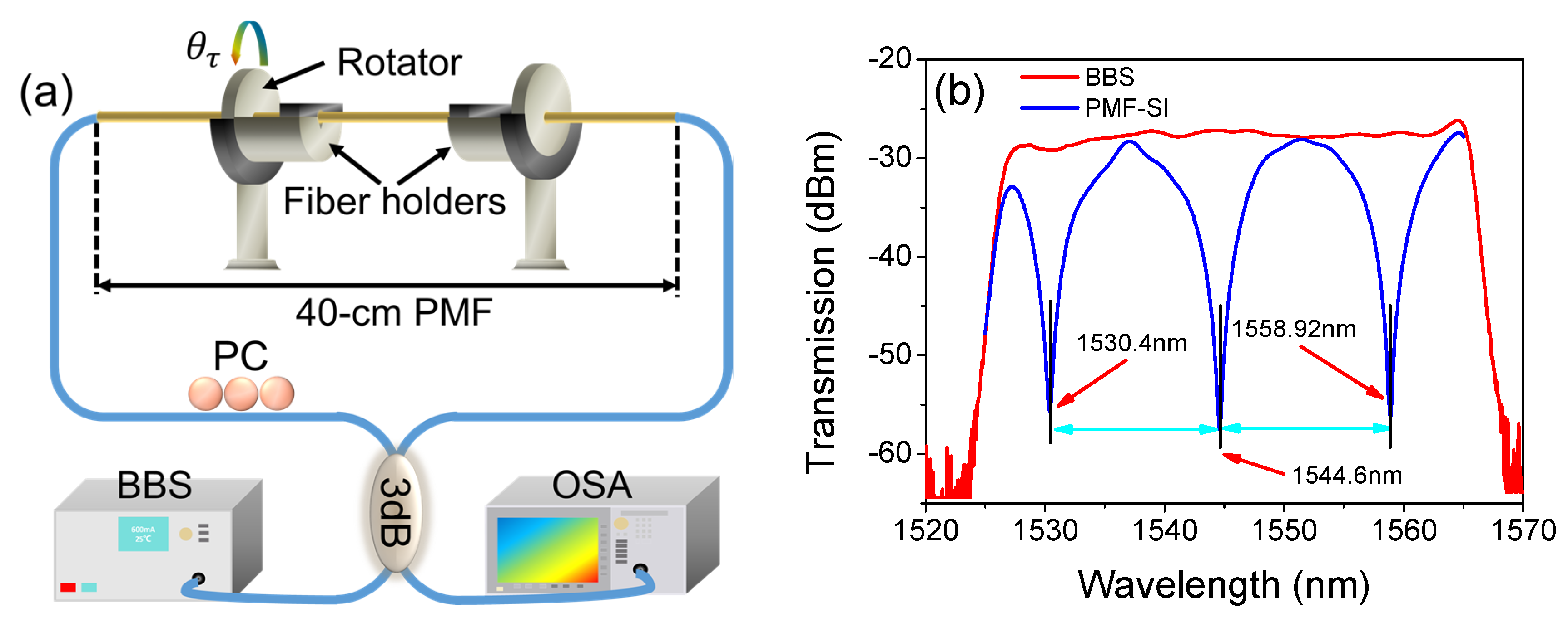
Figure 3.
Spectra evolution of PMF-SI in the clockwise (CW) direction from (a) 0° to 180° and (b) 180° to 360° and the anticlockwise (ACW) direction from (c) 0° to −180° and (d) −180° to −360°.
Figure 3.
Spectra evolution of PMF-SI in the clockwise (CW) direction from (a) 0° to 180° and (b) 180° to 360° and the anticlockwise (ACW) direction from (c) 0° to −180° and (d) −180° to −360°.

Figure 4.
Relationships between the wavelength shift and twist angle in (a) the clockwise direction and (b) the anticlockwise direction.
Figure 4.
Relationships between the wavelength shift and twist angle in (a) the clockwise direction and (b) the anticlockwise direction.
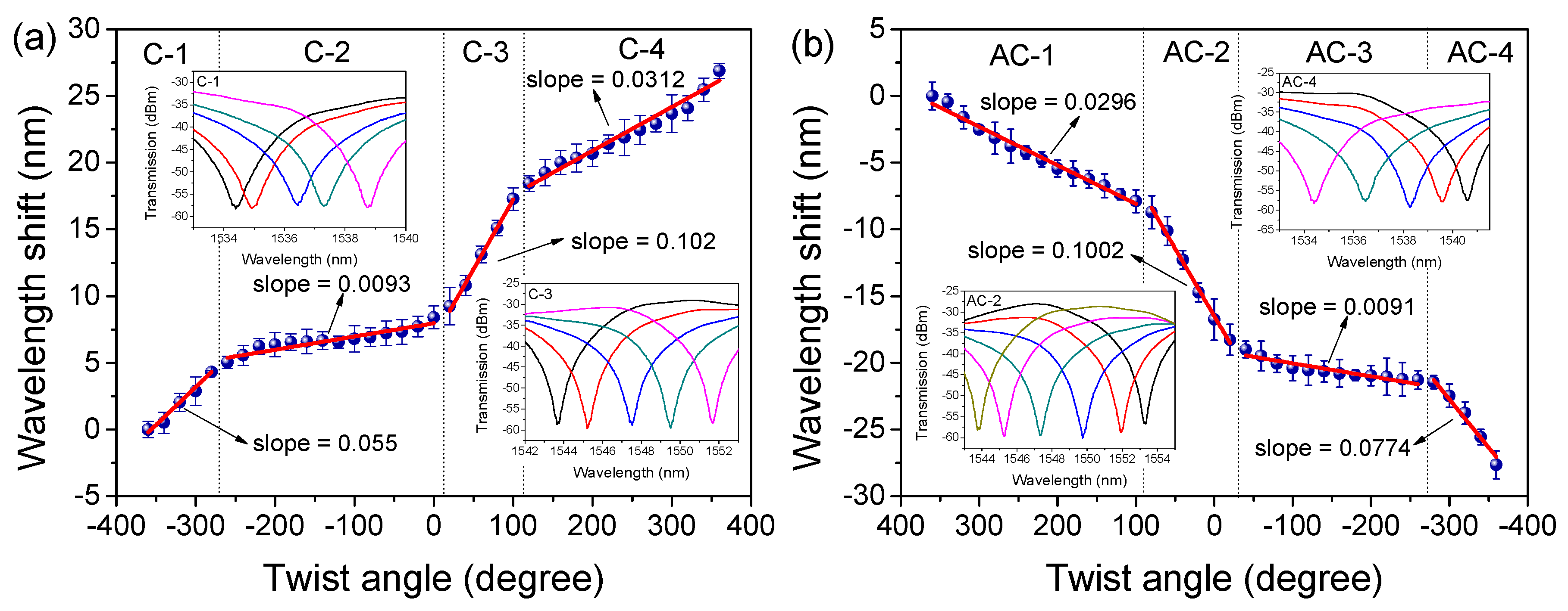
Figure 5.
(a) Numerical simulation of the spectral evolution with the varied and (b) the relationship between wavelength shift and
Figure 5.
(a) Numerical simulation of the spectral evolution with the varied and (b) the relationship between wavelength shift and
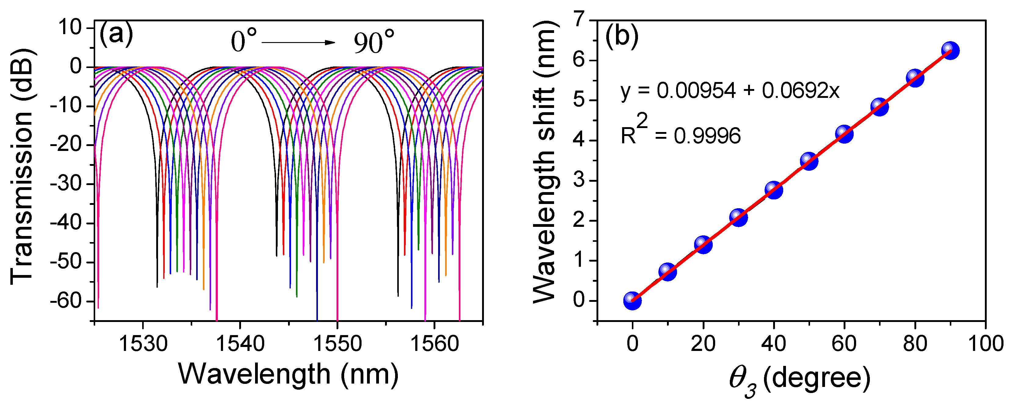
Figure 6.
Interference fringe peak and dip wavelength shift with the changed .

Figure 7.
The schematic diagram of the fiber laser torsion sensor (FLTS). WDM: wavelength division multiplexer, EDF: erbium-doped fiber, ISO: isolator.
Figure 7.
The schematic diagram of the fiber laser torsion sensor (FLTS). WDM: wavelength division multiplexer, EDF: erbium-doped fiber, ISO: isolator.

Figure 8.
(a) The output spectra, (b) extinction ratio (ER) and (c) line width (LW) of the fiber laser ring (FRL) under a varied pump current (from 80 to 200 mA).
Figure 8.
(a) The output spectra, (b) extinction ratio (ER) and (c) line width (LW) of the fiber laser ring (FRL) under a varied pump current (from 80 to 200 mA).
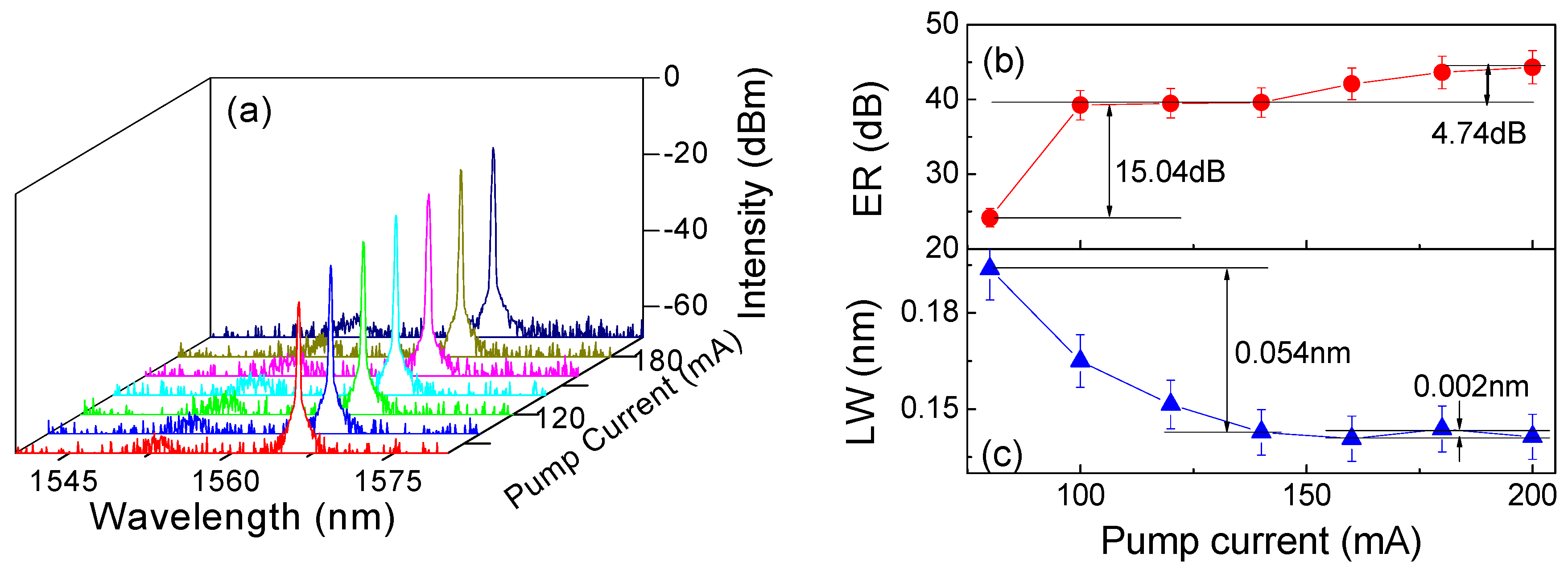
Figure 9.
(a) Twist-induced lasing-wavelength shift and (b) response in the CW direction; (c) Twist-induced lasing-wavelength shift and (d) response in the ACW direction.
Figure 9.
(a) Twist-induced lasing-wavelength shift and (b) response in the CW direction; (c) Twist-induced lasing-wavelength shift and (d) response in the ACW direction.

Figure 10.
The torsion responses with varied ambient temperature.

Figure 11.
The stability of laser wavelengths within 2 hours.


Table 1.
Comparisons of fiber torsion sensors. HPLG: helical long-period gratings. SMF: single-mode fiber.
Table 1.
Comparisons of fiber torsion sensors. HPLG: helical long-period gratings. SMF: single-mode fiber.
| Structures | Linear Response Range | Sensitivity | Direction | Refs. |
|---|---|---|---|---|
| photonic crystal fiber-based SI | approx. −90 to 90 deg | 0.059 nm/deg | Yes | [13] |
| elliptical-core PMF-based SI | approx.−120 to 120 deg | 0.68 nm/deg | Yes | [14] |
| low birefringence SMF-based SI | 180~270 deg | 3.26 nm/deg | No | [17] |
| tapered seven-core fiber | 540~640 deg | 0.88 nm/deg | Yes | [22] |
| reflective Lyot filter | 10~50 deg | 20.336 dB/rad | No | [24] |
| quasi-fan Solc filter | 40~90 deg | 1.27 dB/(rad/m) | No | [37] |
| HLPG-based FLTS | −100 to 100 rad/m | 0.084 nm(rad/m) | Yes | [33] |
| SI-based FLTS | ±300 deg (±175 rad/m) | 2.46 nm/rad | Yes | This work |
© 2019 by the authors. Licensee MDPI, Basel, Switzerland. This article is an open access article distributed under the terms and conditions of the Creative Commons Attribution (CC BY) license (http://creativecommons.org/licenses/by/4.0/).
Share and Cite
MDPI and ACS Style
Liu, X.; Wang, F.; Yang, J.; Zhang, X.; Du, X. Fiber Ring Laser Directional Torsion Sensor with Ultra-Wide Linear Response. Sensors 2019, 19, 3613. https://doi.org/10.3390/s19163613
AMA Style
Liu X, Wang F, Yang J, Zhang X, Du X. Fiber Ring Laser Directional Torsion Sensor with Ultra-Wide Linear Response. Sensors. 2019; 19(16):3613. https://doi.org/10.3390/s19163613
Chicago/Turabian StyleLiu, Xianjin, Fengjuan Wang, Jiuru Yang, Xudong Zhang, and Xiliang Du. 2019. "Fiber Ring Laser Directional Torsion Sensor with Ultra-Wide Linear Response" Sensors 19, no. 16: 3613. https://doi.org/10.3390/s19163613
Note that from the first issue of 2016, this journal uses article numbers instead of page numbers. See further details here.