A Novel Displacement and Tilt Detection Method Using Passive UHF RFID Technology


1
School of Computer Science & Engineering, South China University of Technology, Guangzhou 510006, China
2
School of Electronic & Information, South China University of Technology, Guangzhou 510641, China
3
School of Information Engineering, Guangdong University of Technology, Guangzhou 510006, China
*
Author to whom correspondence should be addressed.
Sensors 2018, 18(5), 1644; https://doi.org/10.3390/s18051644
Submission received: 26 April 2018
/
Revised: 17 May 2018
/
Accepted: 18 May 2018
/
Published: 21 May 2018
(This article belongs to the Special Issue RFID-Based Sensors for IoT Applications)
Abstract
:The displacement and tilt angle of an object are useful information for wireless monitoring applications. In this paper, a low-cost detection method based on passive radio frequency identification (RFID) technology is proposed. This method uses a standard ultrahigh-frequency (UHF) RFID reader to measure the phase variation of the tag response and detect the displacement and tilt angle of RFID tags attached to the targeted object. An accurate displacement result can be detected by the RFID system with a linearly polarized (LP) reader antenna. Based on the displacement results, an accurate tilt angle can also be detected by the RFID system with a circularly polarized (CP) reader antenna, which has been proved to have a linear relationship with the phase parameter of the tag’s backscattered wave. As far as accuracy is concerned, the mean absolute error (MAE) of displacement is less than 2 mm and the MAE of the tilt angle is less than 2.5° for an RFID system with 500 mm working range.
1. Introduction
Wireless monitoring has drawn growing interest in the emerging disciplines of Smart City [1] and Internet of Things (IoT) [2]. Automatic detection of displacement and tilt angle is widely deployed in the supply chain industry. In logistics and transportation, some items are expensive and need real-time location monitoring. For example, for an item with a “This side up” marker, the orientation of the item package should be kept [3]. Compared with optical technologies that are used for the detection of visible items, wireless radio signals or electromagnetic signals are more reasonable choices for invisible targets, such as civil infrastructure health monitoring for a Smart City [4].
Recently, distributed wireless sensor networks (WSN) have been widely deployed for wireless monitoring. Applications include a pervasive network of sensor nodes spread over buildings to detect and identify damage in the building structure [5], and thousands of sensors attached to objects to enable real-time estimation of location [6]. A WSN can provide a distributed set of data that is useful to preventing dangerous events in civil infrastructure, or monitoring local behavior of items in supply chain scenarios. However, limited by the cost of system deployment and the requirement of continuous power sources (e.g., a battery), many applications are not feasible with traditional WSN technologies.
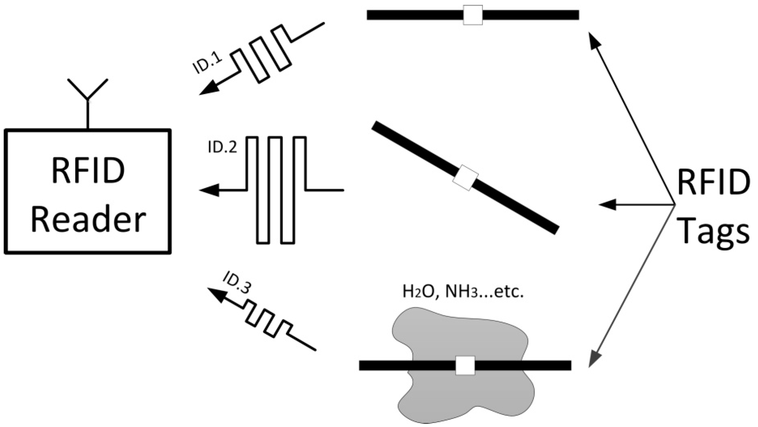
In this paper, a new detection method using radio frequency identification (RFID) technology is proposed to highly reduce the complexity and cost of wireless monitoring systems. RFID is well known as a remote automatic identification technology, which often includes a reader and a tag attached to an object. The tag is energized and interrogated by the reader, through backscattered modulation of the incident continuous wave [7]. An RFID system can provide a radio interface not only for data exchange, but also for sensing capability [8]. Compared with a traditional WSN, an RFID-based sensor has two main cost advantages as follows: Firstly, the battery-less (passive) RFID tag has inherent infinite lifetime, which has a tremendous advantage over high-cost active devices. Secondly, RFID readers and tags are commercial off-the-shelf (COTS) components, instead of a custom-made sensor front-end. As shown in Figure 1, RFID tags achieve different sensing capability by use of uniform electromagnetic information, e.g., drift of resonance frequency or variation of Received Signal Strength Indicator (RSSI) value [9].
Up until now, the published attempts of RFID-based sensors have been focused on physical or chemical factors, such as humidity [10,11,12,13], temperature [14,15,16], gas [16,17,18], strain [19,20], and lab-on-chip (permittivity) [21,22,23]. Based on power measurements [24,25,26], phase detection [27,28,29,30], antenna polarization [31], system analysis [32,33], or multiple tag cooperation [34,35,36], RFID tags can work as sensors for an optional low-cost WSN solution. Different displacement detection approaches can be found in previous works [37,38,39,40,41]. In these papers, tag antennas are physically deformed or damaged by displacement. Unfortunately, as the tag antenna is deformed or broken, it is mismatched, and is hence badly (or even not at all) communicating with the reader. In such a case, it will be very difficult to achieve detection even by using a frequency shift technique, due to the limited allowed RFID bandwidth in USA (902–928 MHz) or Europe (865–868 MHz) [42]. Meanwhile, methods related to tilt detection also have been discussed, which exploits mutual position changing between two tags [43,44,45]. However, accurate angle measurement is difficult to achieve in these attempts.
This paper introduces a novel approach to detecting small displacements and tilt angles of RFID tags. The key idea is to exploit the phase of the backscattered tag response as a carrier of sensing information, while minimizing the degradation of communication performance. Although the phase of the tag response depends on the propagation channel of communication, it can be modified by processing the phase difference of arrival (PDOA) between transmitted and received signals [46]. The methodology of the proposed method is described. Performance testing was carried out with linearly polarized (LP) and circularly polarized (CP) reader antennae. With a 500 mm RFID system working range, the displacement results, which were obtained using an LP reader antenna, demonstrated that the mean absolute error (MAE) was less than 2 mm. Then, based on these displacement results, the tilt angle results, which have a MAE of less than 2.5°, can be obtained using a CP reader antenna with same 500 mm RFID system working range.
The rest of this paper is organized as follows: In Section 2, we present the methodology of the proposed method and the experimental setup. In Section 3, the displacement measurement and tilt angle measurement are described in detail. In Section 4, the limitation conditions of these sensing techniques mentioned above are discussed. Conclusions of the work are drawn in Section 5.
2. Materials and Methods
As shown in Figure 2, the conventional UHF RFID system consists of a passive tag and an RFID reader, which support fully coherent demodulation of the tag signal. The reader operates in full-duplex mode, and transmits a continuous wave to energize the passive tag. The tag sends a modulated response by alternating its reflection coefficient between two states: State 0 and State 1. State 0 is the matching state between the input impedance of the tag antenna and the tag chip. State 1 is a mismatching state and is caused by shorting the internal circuit of the tag chip. As shown in Figure 2, the tag signal can be divided into an I/Q synchronous sample sequence in the time domain through a phase shifter and a band-pass filter (BPF).
2.1. Model
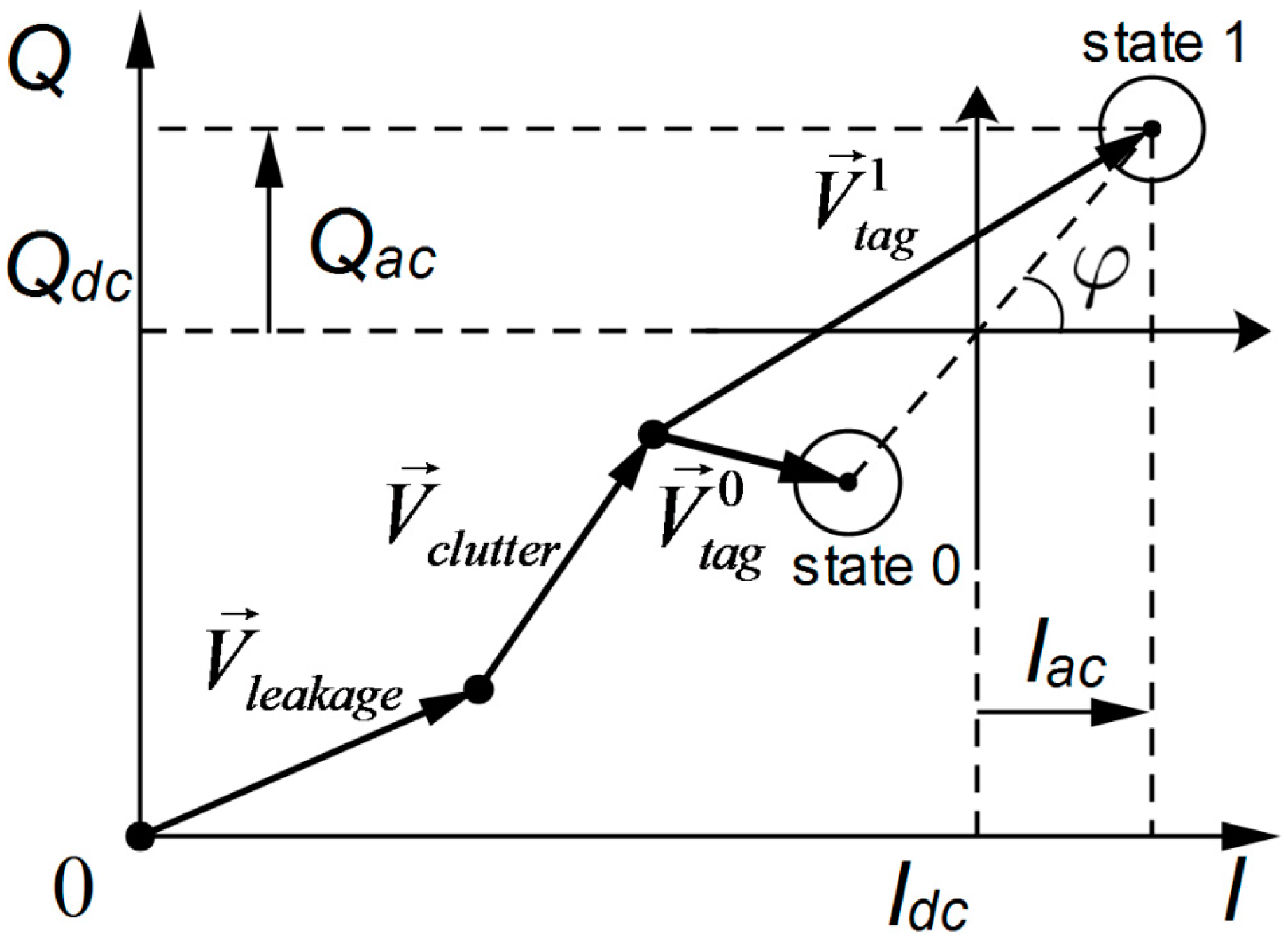
Since the RFID reader can measure both the amplitude and phase of the tag signal by complex demodulation, the tag response can be processed by the reader receiver and transformed into a baseband signal, which can be analyzed on the I–Q vector plane. As shown in Figure 3 [47], it is composed of three components:
where is caused by leakage from the reader transmitter to the receiver; is caused by scattering from the surrounding environment; and is caused by backscattering of the RFID tag, and varied with the states of the tag chip.
Meanwhile, the baseband signal can also be represented by the in-phase and quadrature components, denoted as I(t) and Q(t) in the time domain, respectively. Both components are composed of DC and AC parts, which can be shown as follows:
After removal of the DC part, the reference point of the AC part shown in Figure 2 is centered at zero, and symmetric on the axis of the baseband signal voltage. For illustration, the same reference point shown in Figure 2 can be located at the midpoint between the tag constellation points of State 0 and State 1. Thus, the phase of the received tag signal is defined as follows:
It has been observed that, when the tag is moved away from or towards the reader, both vectors and rotate simultaneously and cause change to the phase of the received signal. Similarly, varies with the relative rotation of the tag antenna linearly, with respect to the reader antenna.
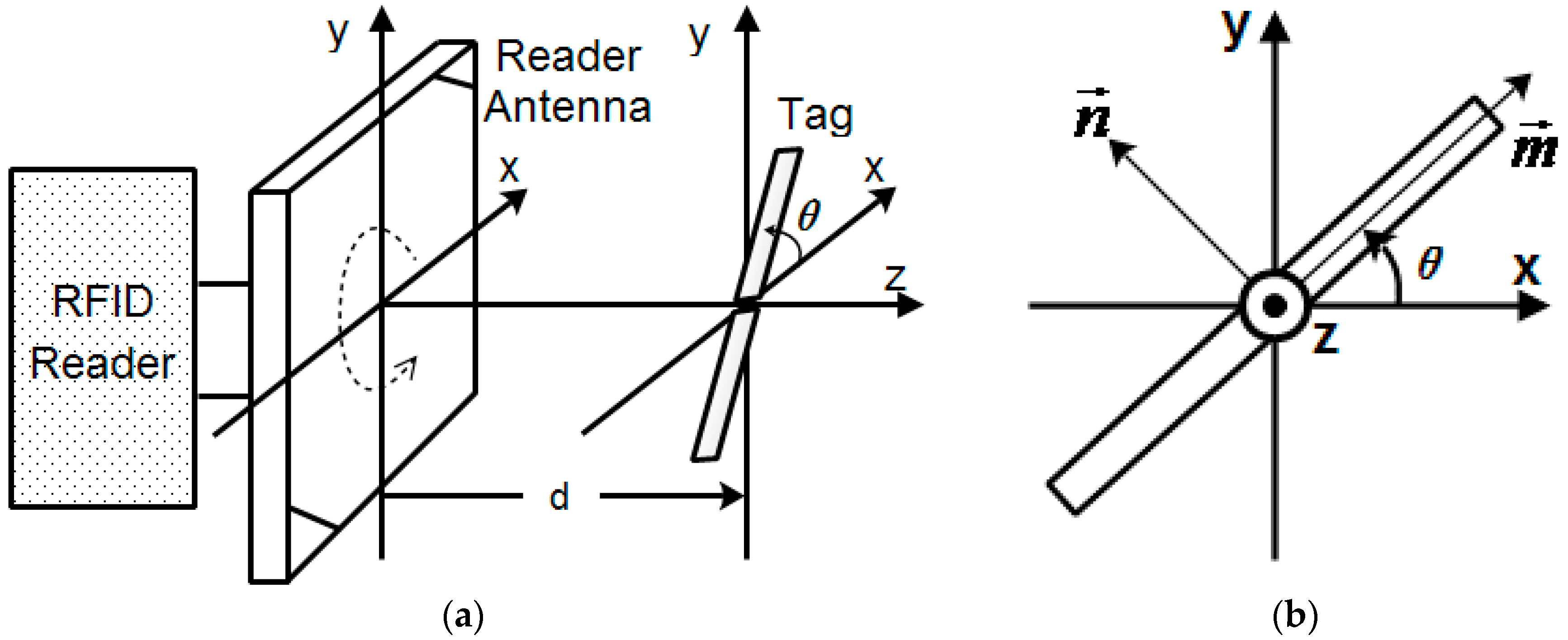
In order to study the phase displacement and phase angle characteristics, we propose the measurement model shown in Figure 4. As shown in Figure 4a, the reader antenna is assumed to be a right-hand circular polarization (RHCP) antenna, and the tag antenna is assumed to be a linear polarization antenna. It is assumed that the surface center of the reader antenna is at the origin (0, 0, 0) of the (x, y, z) coordination system. The tag antenna, which is located on the x–y plane, is parallel to the surface of the reader antenna. Both the reader antenna and the tag antenna are centered and symmetrical on the z axis. The distance between the reader and the tag antenna is measured along the positive z axis. In order to estimate the tilt angle of the tag antenna, we consider the vector along the tag antenna in the linear polarization direction, and the vector in the orthogonal direction, as shown in Figure 4b. The angular relationship toward is referred to as the tilt , defined by counterclockwise rotation beginning at the positive x axis.
2.2. Experimental Setup
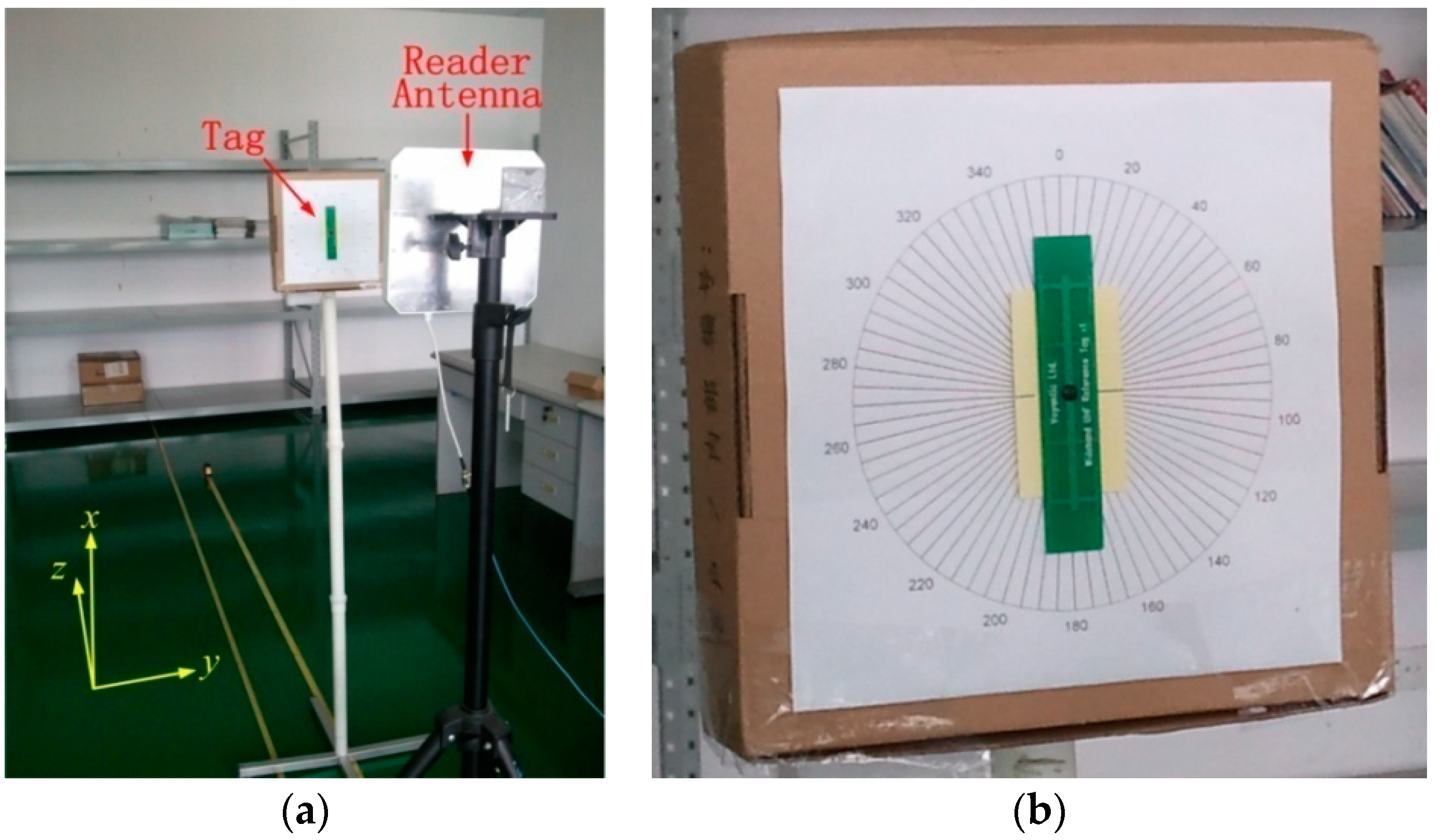
In order to verify the calculation mentioned above, we conducted displacement and tilt angle experiments based on the measurement model outlined in Figure 4. All the experiments were carried out in a real-life lab environment with reflecting surfaces (desks, cabinets, and books, etc.), and a photograph of the test scene is shown in Figure 5a. Therefore, the environmental effects, such as multiple paths, noise, and scattering factors, are a realistic part of the scene.
In these experiments, we used a Laird reader antenna [48] tuned to 902–928 MHz (RHCP and 9 dBic gain) and a Voyantic Field Engineer Kit [49] to simulate the process of an RFID system supporting fully coherent detection. As shown in Figure 5a, a reference RFID tag was parallel to the surface of the reader antenna, and accurately controlled for displacement away or towards the reader antenna, at a step size of 2.54 mm. At each step, the reference tag was interrogated by a carrier power of 20 dBm, and replies were sampled continuously by the Voyantic Field Engineer Kit. The same procedure was repeated for a number of tag angular positions at 5° intervals. For illustration purposes, we marked the passive reference tag on a compass of cardboard, as shown in Figure 5b.
According to the propagation characteristics of the RHCP wave in free space, the electric field intensity of the carrier wave, traveling in the positive z direction, can be written as [50]
Here, is the carrier amplitude, and is the initial phase. The phase constant is , and is the carrier wavelength.
For the tag antenna to have linear polarization in the direction, the received tag signal must have a projection on the direction. That is,
Here, is the carrier wave propagation attenuation, the signal phase difference is , and is the distance of the reader to the tag.
According to the characteristics of a linear polarization antenna, the electric field intensity of the arriving wave at the surface of the reader antenna, backscattered by the linearly polarized tag antenna in the direction, can be written as
Here, is the attenuation of the backscattered path, and is the phase delay during the backscattering process of the tag. is the reflection coefficient of the tag response, which is decided by tag states. If the tag is in matching state (State 0), then . Otherwise, when the tag is in mismatching state (State 1), . It is assumed that the total reader-to-tag-to-reader path is a monostatic channel and has no multipath effect. Thus, the reader-to-tag and tag-to-reader distances can be assumed to be . Hence, the phase difference of the total propagation path is .
The electric field intensity of the linearly polarized arrival wave can also be represented as . and are, respectively, the left-hand circular polarization (LHCP) and RCHP wave components in the negative z direction. According to Equation (6), they can be written as
The two orthogonal vectors, and , are related to the x–y coordinate system by
Since the reader antenna is assumed to be an RHCP antenna and only receive the RCHP component of the arriving wave, we only consider . For coordinates transformed by Equation (8), this can be expressed as
According to Equation (9), the instantaneous scalar expression of the received signal arriving at the reader can be illustrated as [42]
Meanwhile, considering Equation (3), the in-phase and quadrature component of the received signal can also be written as
Considering , we compare Equation (10) with Equation (11), and draw a conclusion that the received tag signal phase is related to the reader-to-tag distance and the tag tilt angle by
Here, is a constant phase offset of the demodulation process, and has an unknown integer number of radian offsets, due to the cycle ambiguity.
3. Results
3.1. Displacement Experiment
We first investigated the received tag signal phase as a function of displacement. The original distance from tag to reader was fixed at , and displacement was defined as , . Meanwhile, the tilt angle was defined as , . For consistent estimation, the tag tilt was fixed to , which leads to . It is clear from Equation (3) that the estimated phase is unambiguous, and that . Considering and , the estimation range is given by
According to Equations (12) and (13), the estimated phase can be expressed by
Here, the carrier wavelength can be seen as constant, and the estimated phase is then proportional to .
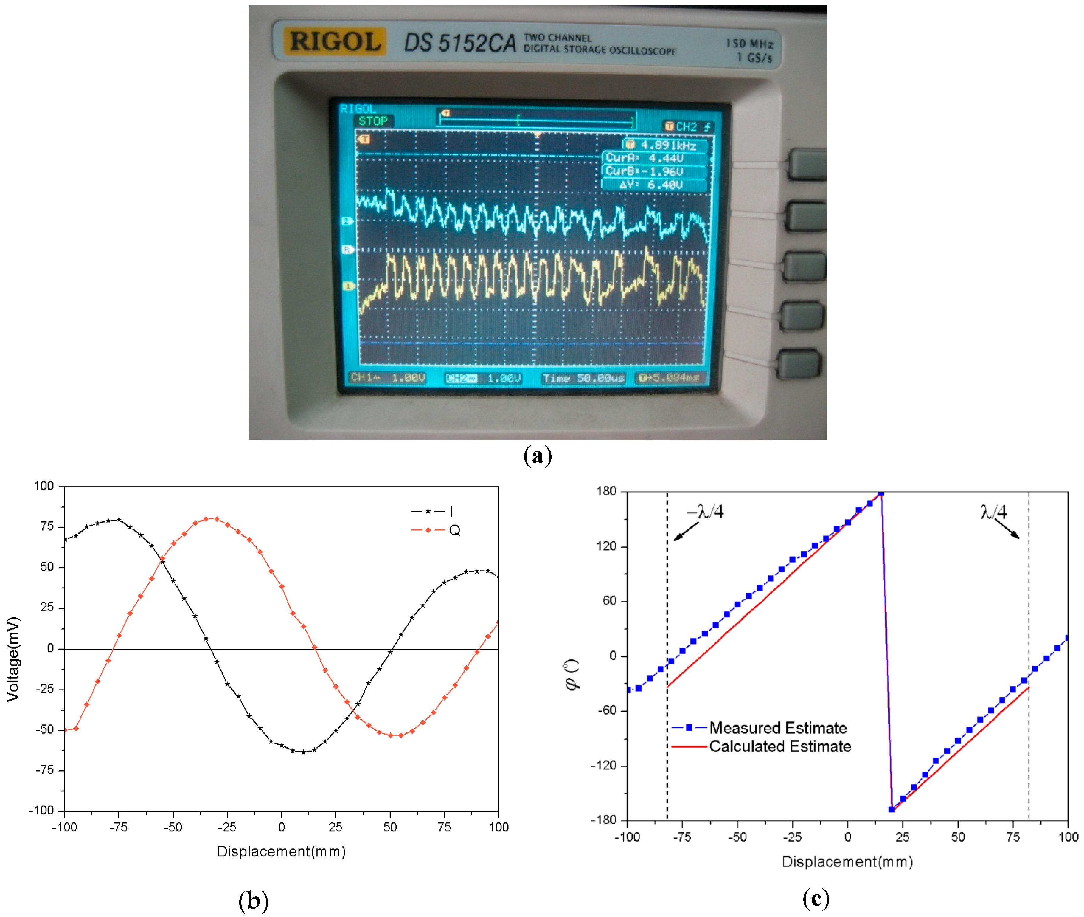
As shown in Figure 6a, the sampled peak–peak voltages at the I/Q channel are given at each step of displacement. We found that sampled curves of the I channel and Q channel are both sine wave curves, and are orthogonal to each other. Moreover, the maximum amplitude of the sine wave curves attenuates quickly with the increase of .
With the measurement method of Figure 6a, original data can be obtained for the displacement measurement, which leads to Figure 6b,c. Based on these sampled voltages in Figure 6b, we can obtain the measured estimate by Equation (3), as shown in Figure 6c. Meanwhile, according to Equation (14), we can calculate the estimate as a function of truth displacement , plotted in Figure 6c. There is a reasonable agreement between the measured and calculated estimates for the received signal phase . The measured estimate results seem to follow a linear trend, and have estimation errors at both ends of the truth displacement due to the phase error accumulation effect. These results primarily validate the correctness of Equation (14), and we can obtain the measured estimate from the measured estimate by using Equation (14). As shown in Figure 7, the measured estimate appears to be fairly linear, and approaches truth displacement . Therefore, it is apparent that the phase parameter of the RFID received signal can be measured for detection of displacement variation, which makes an RFID tag into a displacement sensor.
3.2. Tilt Angle Experiment
In the following, we consider the received tag signal as a function of tilt angle. The definitions of displacement and tilt angle are the same as in the previous measurement. For consistent estimation, we fixed the reader-to-tag distance at , and then . Considering and , the estimation range is given by
From Equation (12) and Equation (15), the estimated phase can be expressed by
Here, the carrier wavelength can be seen as constant, and the estimated phase is then proportional to the tilt angle .
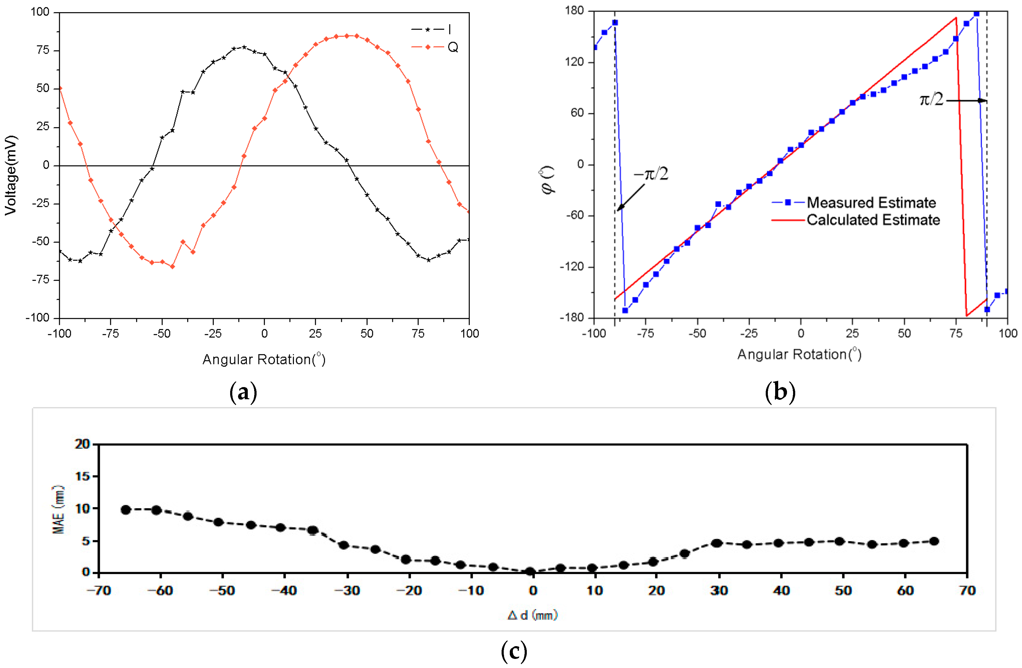
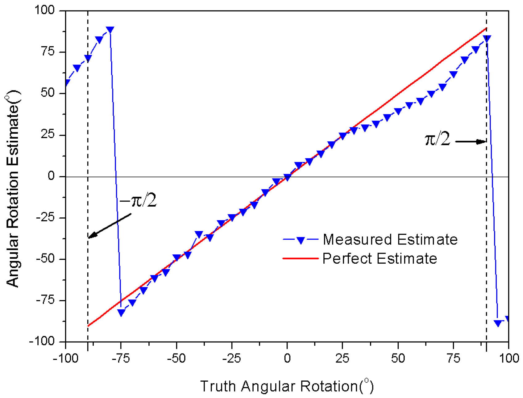
As shown in Figure 8a, the sampled peak–peak voltages at the I/Q channel are given at each interval of the tilt angle, and the reader-to-tag distance maintains constant at . Based on these sampled voltages in Figure 8a, we can obtain the measured estimate by Equation (3), as shown in Figure 8b. Meanwhile, according to Equation (16), we can calculate the estimate as a function of the truth tilt angle , plotted in Figure 8b. There is a reasonable agreement between the measured and calculated estimate for the received signal phase , except between the positions and . The significant fluctuations occur due to the polarization mismatch of the reader antenna. These results primarily validate the correctness of Equation (16), and we can obtain the measured estimate from the measured estimate by using Equation (16). As shown in Figure 9, the measured estimate appears to be quite linear, and agrees well with the truth tilt angle , except between the positions and . If we consider the antenna polarization mismatch effect, the RFID received signal phase can be seen as robust for the detection of angular variation, and can serve as an angular sensor.
4. Discussion
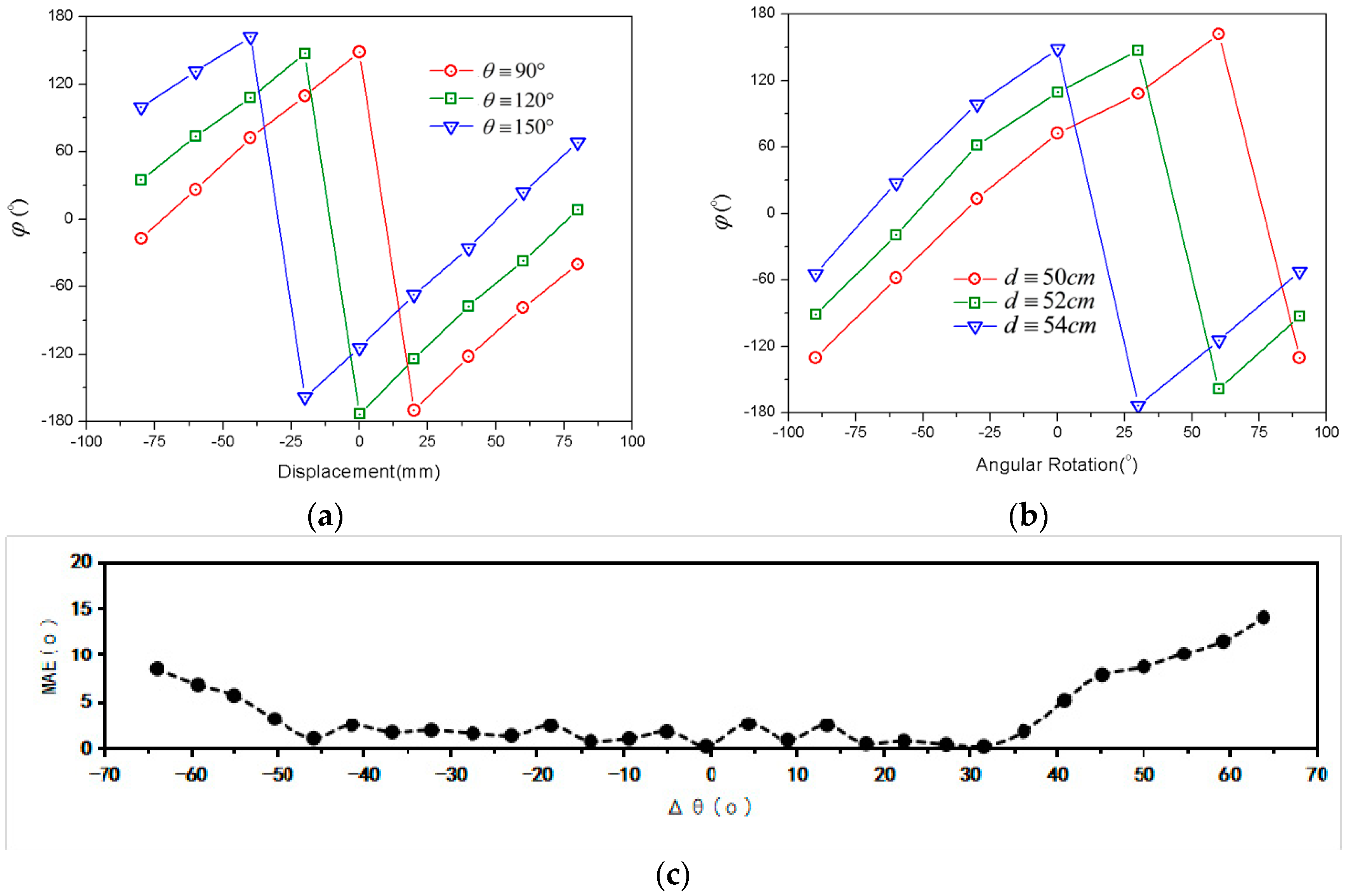
In previous experiments, measurement results of displacement were tested with a fixed tilt angle, and tilt angle data were tested with a static distance. It is necessary to consider the proposed method with different limitation conditions. Experimental results are illustrated in Figure 10. With the increments of initial tilt and distance, the displacement and tilt angle curves are shifted to the left. It should be noted that due to the variation of the limitation condition, the received tag signal phase will not remain unique at a certain position, as shown in Figure 10. It is very difficult to separate the angular effect from displacement effects. Thus, the location results by using the phase-based RFID technique [37,38] are not robust, since they did not consider the effect of tag antenna polarization direction. For consistent purposes, it is desirable that the displacement sensor works with fixed tilt, and the angular sensor with static distance. As shown in Figure 10c, assume that the variation of the tilt angle is less than 30°; then, the MAE of the tilt angle is less than 2.5° for an RFID system with 500 mm working range.
As shown in Table 1, the sensing capability and measurement precision of this paper were compared with previous works. With different system schemes and different measurement methods, a passive RFID system can be used in different sensing applications.
5. Conclusions
In this paper, a novel method for displacement and tilt detection has been validated through theoretic analysis and experiment. A conventional RFID tag attached to an object and an UHF RFID reader were used to compose the proposed detection system. The displacement and tilt angle were estimated respectively using LP and CP reader antennas. With a linear polarization reader antenna, the relation between the phase parameter of the received RFID tag signal and displacement can be proved to be approximately linear through experimental results. Based on previous displacement results, the phase–angle relation of the tag’s backscatter wave, which is close to linear, can also be obtained by a circular polarization reader antenna. Thus, the proposed method can obtain not only the displacement, but also the tilt angle of the tag. It is a reliable and low-cost solution for wireless monitoring applications.
Author Contributions
The work presented in this paper was carried out in collaboration between all authors. X.L. contributed the idea of this paper and designed the experimental setup. The measurement and data analysis were conducted by Z.C. The draft of the manuscript was written by X.L. Z.X. carefully revised this paper and provided insightful suggestions. H.Z. is the coordinator of this paper and takes responsibility for final revision. All authors have read and approved the final manuscript.
Funding
This work was funded by National Natural Science Foundation of China (No. 61101015), Science & Technology Planning Project of Guangdong Province (No. 2011B080701068), and Science & Technology Planning Project of Guangzhou City (No. 201707010060).
Conflicts of Interest
The authors declare no conflict of interest.
References
- Komninos, N. Intelligent Cities; Spon Press London: London, UK, 2003. [Google Scholar]
- Atzori, L.; Iera, A.; Morabito, G. The internet of things: A survey. Comput. Netw. 2010, 54, 2787–2805. [Google Scholar] [CrossRef]
- Musa, A.; Gunasekaran, A.; Yusuf, Y. Supply chain product visibility: Methods, systems and impacts. Expert Syst. Appl. 2014, 41, 176–194. [Google Scholar] [CrossRef]
- Chang, P.C.; Flatau, A.; Liu, S.C. Review paper: Health monitoring of civil infrastructure. Struct. Health Monit. 2003, 2, 257–267. [Google Scholar] [CrossRef]
- Bhuiyan, M.Z.A.; Wang, G.; Cao, J. Deploying wireless sensor networks with fault-tolerance for structural health monitoring. IEEE Trans. Comput. 2015, 64, 382–395. [Google Scholar] [CrossRef]
- Evers, L.; Havinga, P.J.M.; Kuper, J. SensorScheme: Supply chain management automation using wireless sensor networks. In Proceedings of the IEEE International Conference on Emerging Technologies and Factory Automation, Patras, Greece, 25–28 September 2007. [Google Scholar]
- Finkenzeller, K.; Waddington, R. RFID Handbook: Radio-Frequency Identification Fundamentals and Applications, 2nd ed.; Wiley: New York, NY, USA, 2004. [Google Scholar]
- Kim, S.; Mariotti, C.; Alimenti, F.; Mezzanotte, P.; Georgiadis, A.; Collado, A.; Roselli, L.; Tentzeris, M.M. No battery required: Perpetual RFID-enabled wireless sensors for cognitive intelligence applications. IEEE Microw. Mag. 2013, 14, 66–77. [Google Scholar] [CrossRef]
- Occhiuzzi, C.; Caizzone, S.; Marrocco, G. Passive UHF RFID antennas for sensing applications: Principles, methods and classifications. IEEE Antennas Propag. Mag. 2013, 55, 14–34. [Google Scholar] [CrossRef]
- Chang, K.; Kim, Y.-H.; Kim, Y.-J.; Yoon, Y.J. Functional antenna integrated with relative humidity sensor using synthesised polyimide for passive RFID sensing. Electron. Lett. 2007, 43, 259–260. [Google Scholar] [CrossRef]
- Manzari, S.; Occhiuzzi, C.; Nawale, S.; Catini, A.; Di Natale, C.; Marrocco, G. Polymer-doped UHF RFID tag for wireless-sensing of humidity. In Proceedings of the IEEE International Conference on RFID (RFID), Orlando, FL, USA, 3–5 April 2012. [Google Scholar]
- Sauer, S.; Fischer, W.J. An irreversible single-use humidity-threshold monitoring sensor principle for wireless passive sensor solutions. IEEE Sens. J. 2016, 16, 6920–6930. [Google Scholar] [CrossRef]
- Siddiqui, A.; Mahboob, R.; Islam, T. A passive wireless tag with digital readout unit for wide range humidity measurement. IEEE Trans. Instrum. Meas. 2017, 66, 1013–1020. [Google Scholar] [CrossRef]
- Bhattacharyya, R.; Floerkemeier, C.; Sarma, S.; Deavours, D. RFID tag antenna based temperature sensing. In Proceedings of the IEEE International Conference on RFID (RFID), Orlando, FL, USA, 14–16 April 2010. [Google Scholar]
- Babar, A.A.; Manzari, S.; Sydanheimo, L.; Elsherbeni, A.Z.; Ukkonen, L. Passive UHF RFID tag for heat sensing applications. IEEE Trans. Antennas Propag. 2012, 60, 4056–4064. [Google Scholar] [CrossRef]
- Vena, A.; Sydänheimo, L.; Tentzeris, M.M.; Ukkonen, L. A fully inkjet-printed wireless and chipless sensor for CO2 and temperature detection. IEEE Sens. J. 2015, 15, 89–99. [Google Scholar] [CrossRef]
- Abad, E.; Zampolli, S.; Marco, S.; Scorzoni, A.; Mazzolai, B.; Juarros, A.; Gómez, D.; Elmi, I.; Cardinali, G.C.; Gómez, J.M. Flexible tag micro lab development: Gas sensors integration in RFID flexible tags for food logistic. Sens. Actuators B 2007, 127, 2–7. [Google Scholar] [CrossRef] [Green Version]
- Occhiuzzi, C.; Rida, A.; Marrocco, G.; Tentzeris, M. RFID passive gas sensor integrating carbon nanotubes. IEEE Trans. Microw. Theory Tech. 2011, 59, 2674–2684. [Google Scholar] [CrossRef] [Green Version]
- Occhiuzzi, C.; Paggi, C.; Marrocco, G. Passive RFID strain-sensor based on meander-line antennas. IEEE Trans. Antennas Propag. 2011, 59, 4836–4840. [Google Scholar] [CrossRef] [Green Version]
- Occhiuzzi, C.; Marrocco, G. Constrained-design of passive UHF RFID sensor antennas. IEEE Trans. Antennas Propag. 2013, 61, 2972–2980. [Google Scholar] [CrossRef] [Green Version]
- Chin, J.-C.; Rautenberg, J.M.; Ma, C.Y.; Pujol, S.; Yau, D.K. An experimental low-cost, low-data-rate rapid structural assessment network. IEEE Sens. J. 2009, 9, 1361–1369. [Google Scholar] [CrossRef]
- Suwalak, R.; Phongcharoenpanich, C.; Torrungrueng, D.; Krairiksh, M. Determination of dielectric property of construction material products using a novel RFID sensor. Prog. Electromagn. Res. 2012, 130, 601–617. [Google Scholar] [CrossRef]
- Cook, B.S.; Cooper, J.R.; Tentzeris, M.M. An inkjet-printed microfluidic RFID-enabled platform for wireless lab-on-chip applications. IEEE Trans. Microw. Theory Tech. 2013, 61, 4714–4723. [Google Scholar] [CrossRef]
- Occhiuzzi, C.; Marrocco, G. Precision and accuracy in UHF-RFID power measurements for passive sensing. IEEE Sens. J. 2016, 16, 3091–3098. [Google Scholar] [CrossRef]
- Okada, M. Mitigation of detection error in RFID-based in-body localization system. In Proceedings of the 9th Biomedical Engineering International Conference (BMEiCON), Luang Prabang, Laos, 7–9 December 2016. [Google Scholar]
- Kalansuriya, P.; Bhattacharyya, R.; Sarma, S. RFID tag antenna-based sensing for pervasive surface crack detection. IEEE Sens. J. 2013, 13, 1564–1570. [Google Scholar] [CrossRef]
- Paolini, G.; del Prete, M.; Berra, F.; Masotti, D.; Costanzo, A. An agile and accurate microwave system for tracking elderly people occupancy at home. In Proceedings of the IEEE MTT-S Latin America Microwave Conference (LAMC), Puerto Vallarta, Mexico, 12–14 December 2016. [Google Scholar]
- Caizzone, S.; DiGiampaolo, E.; Marrocco, G. Wireless crack monitoring by stationary phase measurements from coupled RFID tags. IEEE Trans. Antennas Propag. 2014, 62, 6412–6419. [Google Scholar] [CrossRef]
- Wang, C.; Xie, L.; Wang, W.; Xue, T.; Lu, S. Moving tag detection via physical layer analysis for large-scale RFID systems. In Proceedings of the IEEE International Conference on Computer Communications, San Francisco, CA, USA, 10–14 April 2016. [Google Scholar]
- Wegener, M.; Froß, D.; Rößler, M.; Drechsler, C.; Pätz, C.; Heinkel, U. Relative localisation of passive UHF-tags by phase tracking. In Proceedings of the International Multi-Conference on Systems, Signals & Devices (SSD), Leipzig, Germany, 21–24 March 2016. [Google Scholar]
- Genovesi, S.; Costa, F.; Borgese, M.; Monorchio, A.; Manara, M. Chipless RFID tag exploiting cross polarization for angular rotation sensing. In Proceedings of the 2016 IEEE International Conference on Wireless for Space and Extreme Environments (WiSEE), Aachen, Germany, 26–28 September 2016. [Google Scholar]
- Ahmed, R.; Avaritsiotis, J.N. The propagation parameters on RFID-localization accuracy. In Proceedings of the Science and Information Conference (SAI), London, UK, 28–30 July 2015. [Google Scholar]
- Khanam, S.; Mahbub, M.; Mandal, A.; Kaiser, M.S.; Mamun, S.A. Improvement of RFID tag detection using smart antenna for tag based school monitoring system. In Proceedings of the International Conference on Electrical Engineering and Information & Communication Technology, Dhaka, Bangladesh, 10–12 April 2014. [Google Scholar]
- Rizzoli, V.; Costanzo, A.; Montanari, E.; Benedetti, A. A new wireless displacement sensor based on reverse design of microwave and millimeter-wave antenna array. IEEE Sens. J. 2009, 9, 1557–1566. [Google Scholar] [CrossRef]
- Han, J.; Qian, C.; Wang, X.; Ma, D.; Zhao, J.; Zhang, P.; Xi, W.; Jiang, Z. Twins: Device-free object tracking using passive tags. In Proceedings of the IEEE/ACM Transactions on Networking, Toronto, ON, Canada, 27 April–2 May 2014. [Google Scholar]
- Caizzone, S.; Giampaolo, E.D.; Marrocco, G. Setup-independent phase-based sensing by UHF RFID. IEEE Antennas Wirel. Propag. Lett. 2017, 16, 2408–2411. [Google Scholar] [CrossRef]
- Cazeca, M.J.; Mead, J.; Chen, J.; Nagarajan, R. Passive wireless displacement sensor based on RFID technology. Sens. Actuators A 2013, 190, 197–202. [Google Scholar] [CrossRef]
- Cook, B.S.; Shamim, A.; Tentzeris, M.M. Passive low-cost inkjet-printed smart skin sensor for structural health monitoring. IET Microw. Antennas Propag. 2012, 6, 1536–1541. [Google Scholar] [CrossRef]
- Becker, J.; Trotter, M.S.; Griffin, J.D. Passive displacement sensing using backscatter RFID with multiple loads. In Proceedings of the IEEE SENSORS, Baltimore, MD, USA, 3–6 November 2013. [Google Scholar]
- Paggi, C.; Occhiuzzi, C.; Marrocco, G. Sub-millimeter displacement sensing by passive UHF RFID antennas. IEEE Trans. Antennas Propag. 2014, 62, 905–912. [Google Scholar] [CrossRef] [Green Version]
- Perret, E. Displacement sensor based on radar cross-polarization measurements. IEEE Trans. Microw. Theory Tech. 2017, 65, 955–966. [Google Scholar] [CrossRef]
- UHF. Frequency Regulations—GS1. Available online: http://www.gs1.org/docs/epcglobal/UHF_Regulations.pdf (accessed on 20 May 2018).
- Krigslund, R.; Popovski, P.; Pedersen, G.F. Orientation sensing using multiple passive rfid tags. IEEE Antennas Wirel. Propag. Lett. 2012, 11, 176–179. [Google Scholar] [CrossRef]
- Gupta, G.; Singh, B.P.; Bal, A. Orientation detection using passive UHF RFID technology. IEEE Aantennas Propag. Mag. 2014, 56, 221–237. [Google Scholar] [CrossRef]
- Krigslund, R.; Dosen, S.; Popovski, P. A novel technology for motion capture using passive UHF RFID tags. IEEE Trans. Biomed. Eng. 2013, 60, 1453–1457. [Google Scholar] [CrossRef] [PubMed]
- Li, X.; Zhang, Y.; Amin, M.G. Multi frequency-based range estimation of RFID tags. In Proceedings of the IEEE International Conference on RFID (RFID), Orlando, FL, USA, 27–28 April 2009. [Google Scholar]
- Nikitin, P.V.; Martinez, R.; Ramamurthy, S.; Leland, H.; Spiess, G.; Rao, K. Phase based spatial identification of UHF RFID tags. In Proceedings of the IEEE International Conference on RFID (RFID), Orlando, FL, USA, 14–16 April 2010. [Google Scholar]
- Circular Polarity RFID Panel Antenna S9028PCL S9028PCR. Available online: https://assets.lairdtech.com/home/brandworld/files/ANT-DS-S9028PCL%20S9028PCR-0515.pdf (accessed on 20 May 2018).
- Field Engineer Kit. Available online: http://voyantic.com/products/tagformance-pro/accessories/field-engineer-kit (accessed on 20 May 2018).
- Balanis, C.A. Antenna Theory: Analysis and Design, 3rd ed.; Wiley: New York, NY, USA, 2005. [Google Scholar]
Figure 1.
Commercial off-the-shelf (COTS) system of radio frequency identification (RFID) for identification and different sensing applications.
Figure 1.
Commercial off-the-shelf (COTS) system of radio frequency identification (RFID) for identification and different sensing applications.

Figure 2.
Ultrahigh-frequency (UHF) RFID system block diagram.
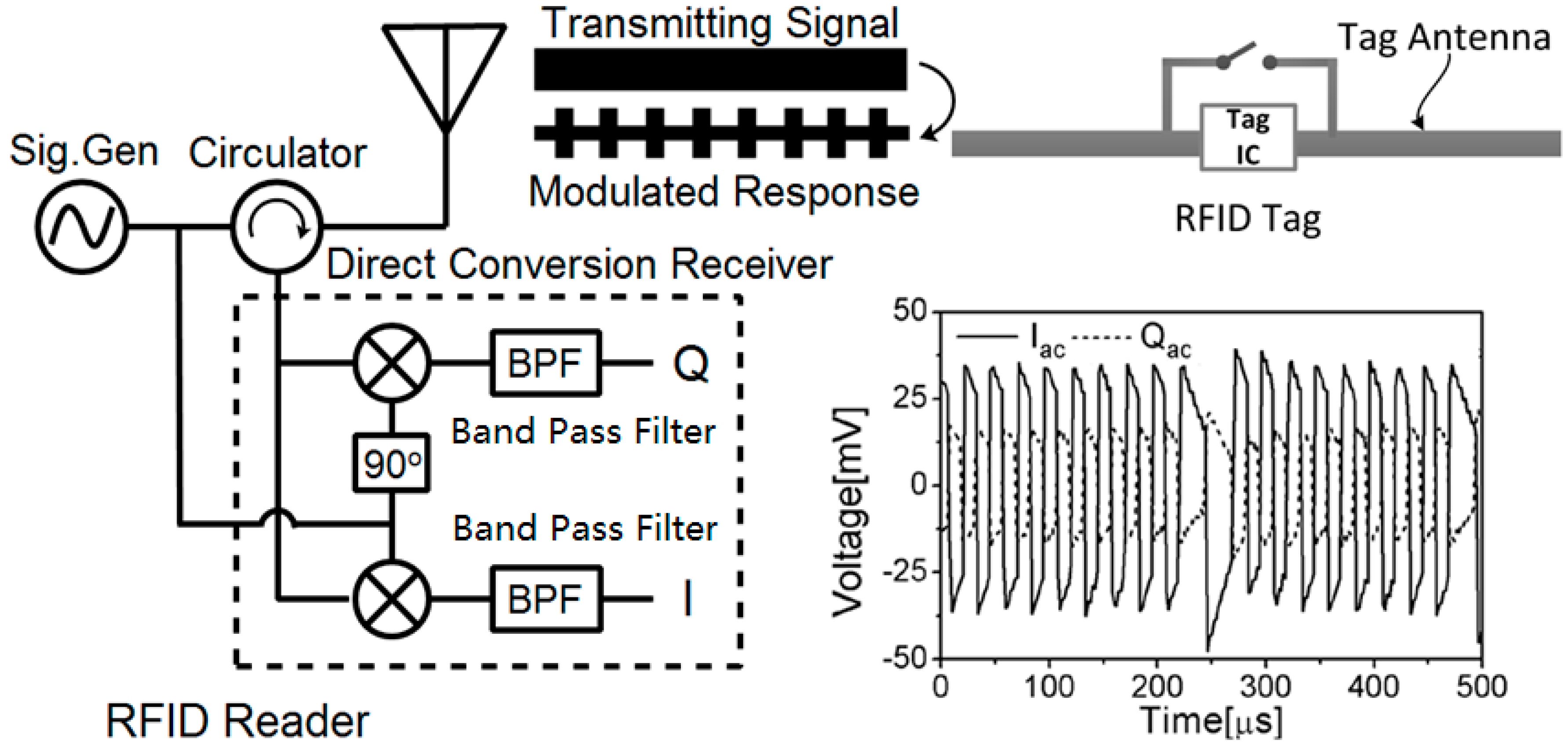
Figure 3.
Tag response on the I–Q vector plane [47].
Figure 3.
Tag response on the I–Q vector plane [47].

Figure 4.
Measurement model: (a) Experimental scheme. (b) Angular relationship of tag antenna.

Figure 5.
Experimental measurement: (a) Test setup. (b) Markers illustrating the tag orientation.

Figure 6.
Displacement measured results: (a) Original source of measurement data; (b) Sampled voltages at I/Q channel; (c) Estimated phase as a function of displacement.
Figure 6.
Displacement measured results: (a) Original source of measurement data; (b) Sampled voltages at I/Q channel; (c) Estimated phase as a function of displacement.

Figure 7.
Comparison between measured and perfect estimated displacement.

Figure 8.
Tilt angle results: (a) Sampled voltages at the I/Q channel; (b) Estimated phase as a function of tilt angle; (c) Mean absolute error (MAE) result between measured and calculated estimate.
Figure 8.
Tilt angle results: (a) Sampled voltages at the I/Q channel; (b) Estimated phase as a function of tilt angle; (c) Mean absolute error (MAE) result between measured and calculated estimate.

Figure 9.
Comparison between measured and perfect estimated tilt angle.

Figure 10.
Experimental results with different limitation conditions: (a) Displacement curves with different tilt limitations; (b) Angular curves with different position limitations; (c) MAE result between measured and calculated estimate for .
Figure 10.
Experimental results with different limitation conditions: (a) Displacement curves with different tilt limitations; (b) Angular curves with different position limitations; (c) MAE result between measured and calculated estimate for .


Table 1.
Comparison of sensing capability and measurement precision.
| Measurement Methods | Displacement Sensing | Tilt Angle Sensing | Measurement Precision of Displacement | Measurement Precision of Tilt Angle |
|---|---|---|---|---|
| Double phase difference [36] | Yes | NA | 6° (phase) 1 | NA |
| Transmitted power monitoring [37] | Yes | NA | 2% (Power) 1 | NA |
| Received signal strength [43] | NA | Yes | NA | 7° |
| Antenna polarization [44] | NA | Yes | NA | 15° |
| [this paper] | Yes | Yes | 2 mm | 2.5° |
1 Conversion is required for displacement data.
© 2018 by the authors. Licensee MDPI, Basel, Switzerland. This article is an open access article distributed under the terms and conditions of the Creative Commons Attribution (CC BY) license (http://creativecommons.org/licenses/by/4.0/).
Share and Cite
MDPI and ACS Style
Lai, X.; Cai, Z.; Xie, Z.; Zhu, H. A Novel Displacement and Tilt Detection Method Using Passive UHF RFID Technology. Sensors 2018, 18, 1644. https://doi.org/10.3390/s18051644
AMA Style
Lai X, Cai Z, Xie Z, Zhu H. A Novel Displacement and Tilt Detection Method Using Passive UHF RFID Technology. Sensors. 2018; 18(5):1644. https://doi.org/10.3390/s18051644
Chicago/Turabian StyleLai, Xiaozheng, Zhirong Cai, Zeming Xie, and Hailong Zhu. 2018. "A Novel Displacement and Tilt Detection Method Using Passive UHF RFID Technology" Sensors 18, no. 5: 1644. https://doi.org/10.3390/s18051644
Note that from the first issue of 2016, this journal uses article numbers instead of page numbers. See further details here.