Optical Graphene Gas Sensors Based on Microfibers: A Review

Fiber Optics Research Centre, Key Laboratory of Optical Fiber Sensing and Communications (Education Ministry of China), University of Electronic Science and Technology of China, Chengdu 610054, China
*
Authors to whom correspondence should be addressed.
Sensors 2018, 18(4), 941; https://doi.org/10.3390/s18040941
Submission received: 31 December 2017
/
Revised: 25 January 2018
/
Accepted: 3 February 2018
/
Published: 22 March 2018
(This article belongs to the Special Issue Optical Sensors based on Micro/Nanofibres)
Abstract
:Graphene has become a bridge across optoelectronics, mechanics, and bio-chemical sensing due to its unique photoelectric characteristics. Moreover, benefiting from its two-dimensional nature, this atomically thick film with full flexibility has been widely incorporated with optical waveguides such as fibers, realizing novel photonic devices including polarizers, lasers, and sensors. Among the graphene-based optical devices, sensor is one of the most important branch, especially for gas sensing, as rapid progress has been made in both sensing structures and devices in recent years. This article presents a comprehensive and systematic overview of graphene-based microfiber gas sensors regarding many aspects including sensing principles, properties, fabrication, interrogating and implementations.
1. Introduction
Microfibers with sub-wavelength geometry and large index contrast between the fiber core and surroundings [1,2] has become a widely used technique in fiber optics, benefiting from its outstanding properties: evanescent field excitation, electromagnetic confinement, low transmission loss, and coupling convenience [3,4]. Among diverse microfiber applications, optical sensing is very interesting due to its potential of realizing miniaturized fiber optic sensors with small footprint, high sensitivity, fast response, good flexibility, and low power consumption [5,6]. Especially in recent years, people have found that microfibers can work as an ideal substrate for realizing high-performance chemical sensors incorporated with two-dimensional optoelectronic materials, such as graphene or graphene oxide.
Graphene is a unique two-dimensional material composed of carbon in a honeycomb lattice with atomic thickness [7,8], and has spurred remarkable advances ranging from chemical physics and materials science [9,10], to optoelectronics, mechanics, and thermal processes [11,12,13,14]. In photonics, driven by its quasiparticle Dirac fermions obeying a linear dispersion and chiral symmetry [15,16], graphene enables its optical conductivity defined only by the fine structure constant [17], which is with remarkable carrier-density tunability and corresponding surface sensitivity [18,19,20,21]. Consequently, a series of state-of-the-art graphene-based optoelectronic and photonic devices have been investigated, including modulators, fast lasers, detectors, converters, and biochemical sensors [22,23,24,25,26,27,28,29].
Among them, graphene-based gas detection is one of the most creative and successful applications, showing the potential to achieve ultimate sensitivity: single molecule gas detection [30]. Moreover, benefiting from its atomic thickness with ultrahigh conductivity, graphene can also realize remarkable functionalities, such as wearable sensors for smart systems [31,32,33] and switching-sensing devices for high-precision measurements with thermal compensation [34,35].
When deposited on microfibers, graphene interacts with the evanescent field, enabling different kinds of graphene-based microfiber gas sensors. Here we conclude the recent progress in this fiend regarding their sensing principles, fabrication and performances. Typical graphene-based microfiber gas sensors include biconical tapers, gratings, interferometers, coils, ring cavities, and so on. These fiber-optic graphene gas sensors are categorized in both passive (such as interferometric) and active (such as pumping laser-based) techniques, which shows the potential applications in highly-sensitive gas sensing in combining with microfiber and new materials. Although some review articles on graphene-based electrical gas sensors have been published [9,10], there are currently no available review articles on graphene-based microfiber gas sensors. Hence, this article aims to provide an overview of the research and development on graphene-based microfiber gas sensors over the past 5 years. Finally, we summarize with an outlook for challenges and opportunities of the optical graphene gas sensors based on microfibers.
2. Principles of Graphene-Based Gas Sensing on Microfibers
The electronic conductive band and valence band crosses at the Dirac point, as shown in Figure 1a [36]. The Fermi level of graphene can be simply described by using the dispersion relation E±(κ) = ±ħνF|κ|, where κ is the wave vector, νF ≈ 106 m/s is the Fermi velocity, and ħ is Planck’s constant [37]. When the Fermi level is higher than the Dirac point, graphene is N-doped; otherwise it is P-doped. Accordingly, the optical conductivity of graphene can be written as [38]:
Specifically, the intraband conductivity and the interband conductivity can be approximately separated as:
The theoretically calculated results are shown in Figure 1b. Here EF is the quasi Fermi level, directly determined by the external bias. f is the optical frequency, τ ≈ 10−13 s is the carrier relaxation lifetime, T is the temperature, fd(ϵ) = {exp[(ϵ-μ)/kBT] + 1}−1 is the Fermi–Dirac distribution, ħ = 1.05 × 10⁻³⁴ J·s, kB = 1.3806505 × 10⁻²³ J/K is Boltzmann’s constant, and e = −1.6 × 10⁻¹⁹ C is the unit charge. External electric tuning majorly influences the σg,inter, which is also directly related to the saturable absorption, which is driven by the photoexcited electron kinetics [39]. Considering the fact that graphene has an atomically thick planar waveguide with such a complex sheet conductivity, we write its effective optical permittivity as
where Re(σg) and Im(σg) are the real and imaginary parts of σg, respectively. By regarding the graphene monolayer thickness Δ = 0.4 nm, the refractive index of the graphene layer can be derived from [40]:
For media modes with real permittivity, we can calculate the relationship as
Figure 1c maps the numerically calculated results of the complex permittivity and complex refractive index. These results directly indicate the optical dispersion of graphene-based microfiber structures, which was experimentally demonstrated by Yao et al. in 2013 [41].
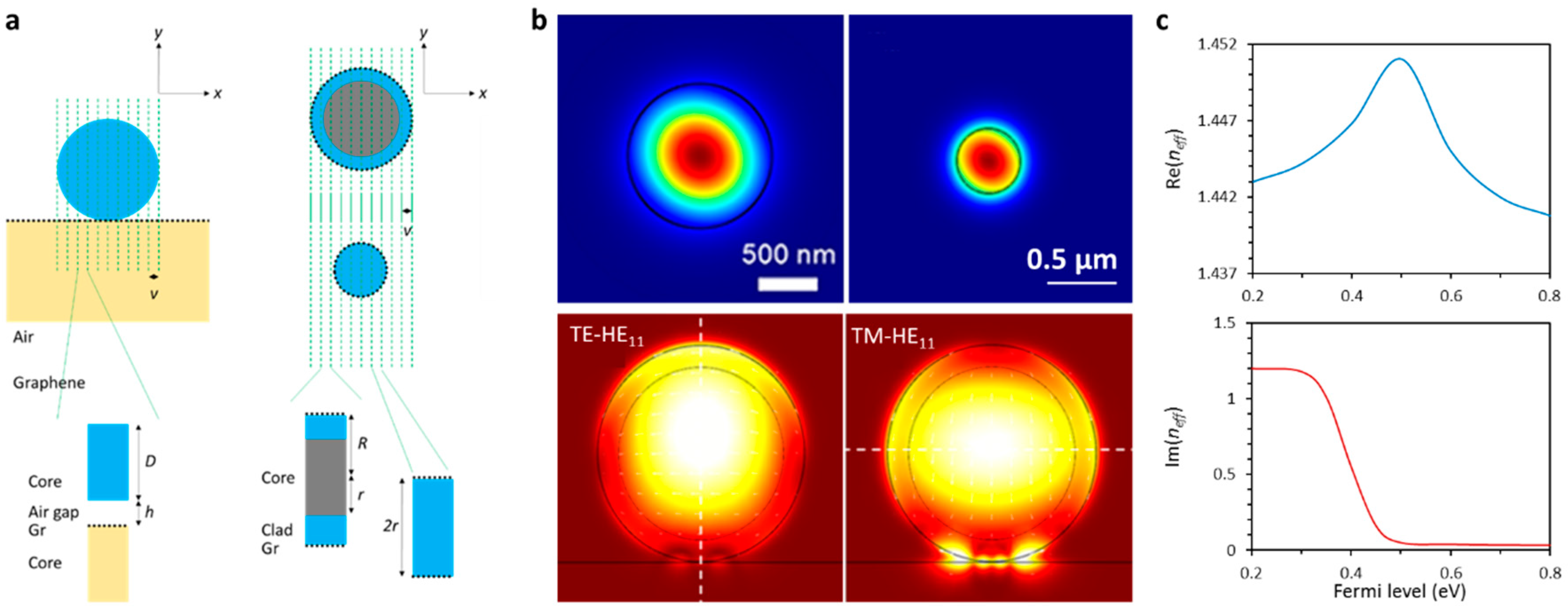
Once incorporated with a microfiber, the graphene performs as a part of the cladding, and can influence the optical transmission via mode effective refractive index modulation. According to different graphene–microfiber hybrid geometries, the mode field distributions and complex effective index neff can be numerically simulated or calculated via finite element method (FEM) [43,44]. Figure 2a illustrates the idea of modelling the graphene-based microfibers for effective index approximation. Figure 2b provides examples of the spatial distributions of electric field intensity (fundamental mode) for different types of graphene-based microfiber structures. Upper panels: graphene-wrapped microfiber with core diameter ≈ 0.5 µm and 1 µm [43,45], lower panels: graphene-wrapped microfiber with core diameter ≈ 8 µm while cladding thickness ≈ 2 µm [46]. The mode effective index of a hybrid waveguide is also influenced by the optoelectronic dynamics of graphene. Figure 2c plots the simulated “neff vs. |EF|” correlation of a graphene-based microfiber with core diameter ≈ 8 µm. It can be seen that by changing the Fermi level of graphene, both the transmission phase and the transmission loss of a graphene-based microfiber could be modified remarkably. Such a mechanism can not only be applied to sensing, but has also been widely used for fast optical modulation [47,48].
It is known that the electromagnetic field distributed along microfibers obeys the Bessel equations in cylindrical coordinates [49], which has a general solution
where A is the optical amplitude, Re(neff) and Im(neff) are the real and imaginary parts of the graphene-based microfiber, z is the transmission distance, t is the time delay, c is the light velocity in vacuum, and ω is the optical frequency. As a conclusion, the Fermi-level modification of graphene would modulate both the output phase and output power of the microfiber. In optical nonlinear processes, such an effect also alters the phase-matching and nonlinear threshold [50].
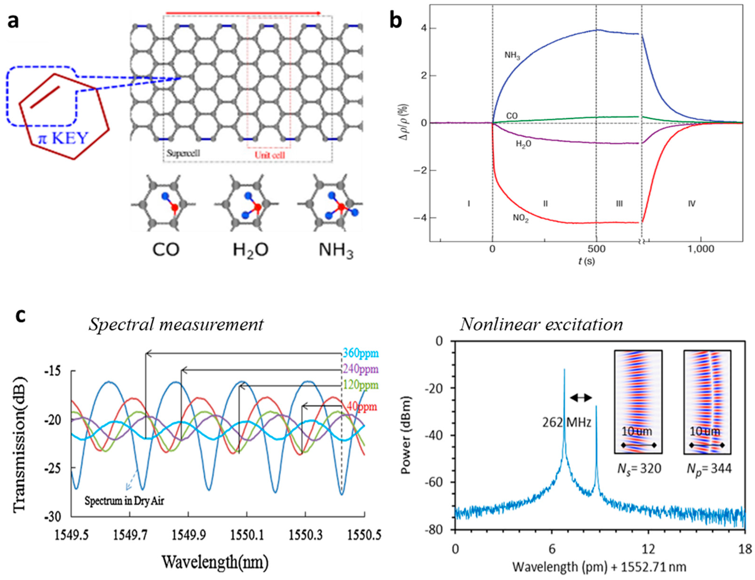
When gas molecules are adsorbed on the surface of graphene, the Fermi level of graphene is tuned [54,55]. Figure 3a shows chemical connections between graphene and gas molecules schematically. For pristine graphene film, the absorption of polar molecules is dominant, hence pristine graphene had been demonstrated with high electronic sensitivity to polar gases such as NH3, NO2, and H2O. It is worth pointing out that for graphene oxide (GO) or other functionalized graphene, non-polar gas such as H2 is also detectable [56]. Figure 3b plots the measured “gas adsorption vs. conductivity” for graphene film, reported in Ref. [30]. As expounded above, the “gas adsorption” and the “conductivity-index relationship” of graphene form the basis of the optical graphene gas sensing. By using microfibers, the gas adsorption can be detected via optical interference, power metering, or nonlinearity excitation, as shown in Figure 3c.
3. Design and Fabrication of Graphene-Based Microfiber Structures
Since the first graphene-based microfiber optical gas sensor reported in 2012 [57], a variety of graphene-microfiber hybrid structures have been investigated for gas sensing applications. Their fabrication process can be summarized with the following three steps: (1) microfiber fabrication; (2) graphene growth; (3) graphene-microfiber installation.
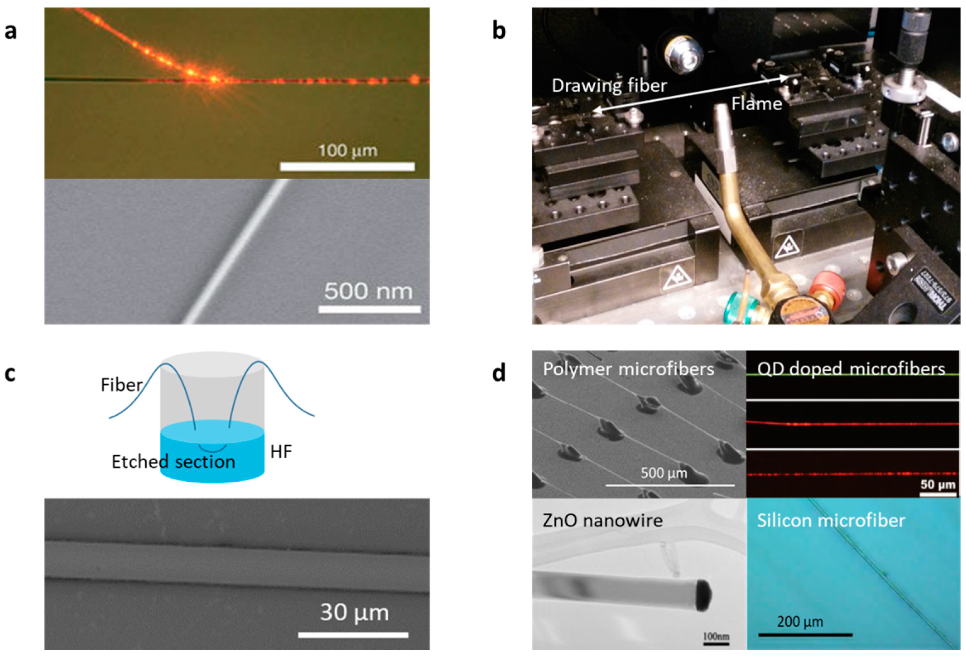
Typically, microfibers are fabricated from commercial glass fibers or bulks, by using the fusing & drawing method [1], which can be controlled either manually or automatically. Figure 4a shows the microscopic pictures of typical microfibers. The heater source can be either a flame (usually a hydrogen flame), an electrical heater, or a laser-heated tube [58,59,60]. Figure 4b demonstrates a typical setup for fusing & drawing microfibers from glass fibers. Optical loss of a microfiber is mainly determined by its taper quality. Very recently, taking advantage of the “flame-brushing” technique, high-quality silica micro-nano fibers with diameters in the range of 800 nm to 1.3 µm, unevenness < 5 nm, and waist length larger than 30 cm have been achieved [61].
Sometimes one not only wants a microfiber-guiding evanescent field, but also hopes to keep the inner microstructures of the original fiber (such as photonic crystals and Bragg gratings); then, chemical etching becomes a choice [67,68]. For example, for silica-based fiber etching, hydrofluoric acid is commonly used as the corrosive agent. Compared to microfibers fabricated by fusing & drawing, the chemically etched microfibers have larger average diameters, usually in the range of 8–12 µm. Figure 4c shows this method and pictures of the chemically etched microfiber samples. In addition, for further specific purposes, microfibers are not only fabricated from glass materials, but also other materials such as polymers, silicon, and metal-oxides, by using diverse means such as thermal process, chemical growth, and self-assembly [62,63,64,65,66]. Figure 4d shows examples of these special microfibers.
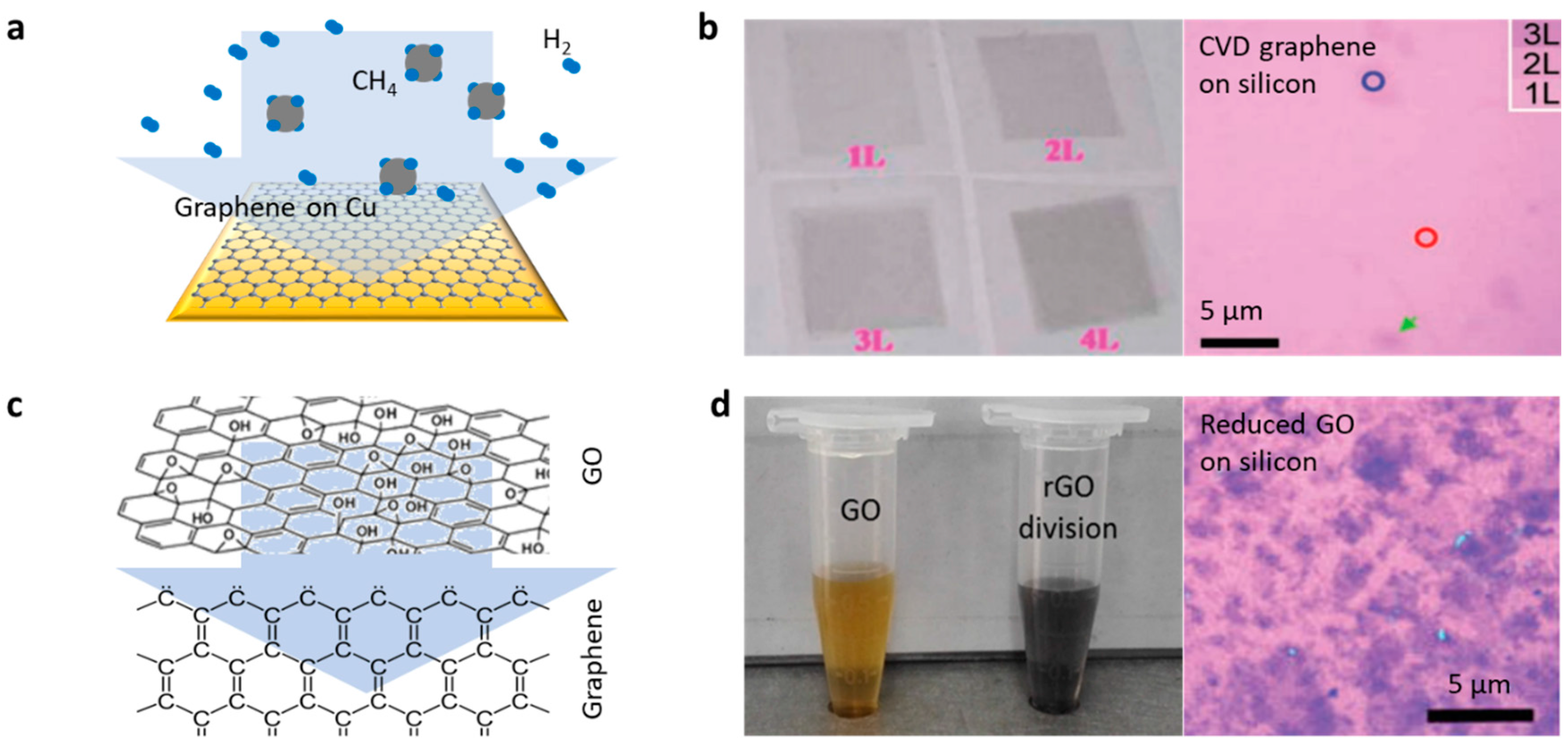
The chemical vapor deposition (CVD) and wet transfer techniques provide inch-level large-scale monolayer graphene for incorporation with microfibers [69,70,71,72]. Figure 5a illustrates a schematic view of a growing graphene film on a copper foil. Graphene on Cu is grown by the decomposition of CH4 gas in a dilute H2 environment over the surface at 1000 °C. With the exposure of Cu foil in a CH4/H2 environment, the nucleation of graphene islands starts taking place randomly, eventually aggregating into a continuous graphene film. Figure 5b shows the optical image and pictures of CVD graphene film samples. CVD graphene has good uniformity in inch-size large-scale, which has been widely used in optoelectronic devices, via the wet transfer technique. Graphene films can also be deposited on fiber structures directly by reducing from GO in liquid. Figure 5c shows the chemical structures of GO and graphene; there are many functional groups containing oxygen connecting the carbon atoms [73]. Figure 5d shows pictures of liquid dispersions of GO and graphene reduced from GO [74]. Compared to CVD graphene films, the reduced GO film usually has more defects, but the deposition of the GO film does not need an additional transferring process, which is more convenient for implementation. In recent years, by optimizing the solution-based reduction method, large-area GO films with acceptable uniformity can be obtained [75].
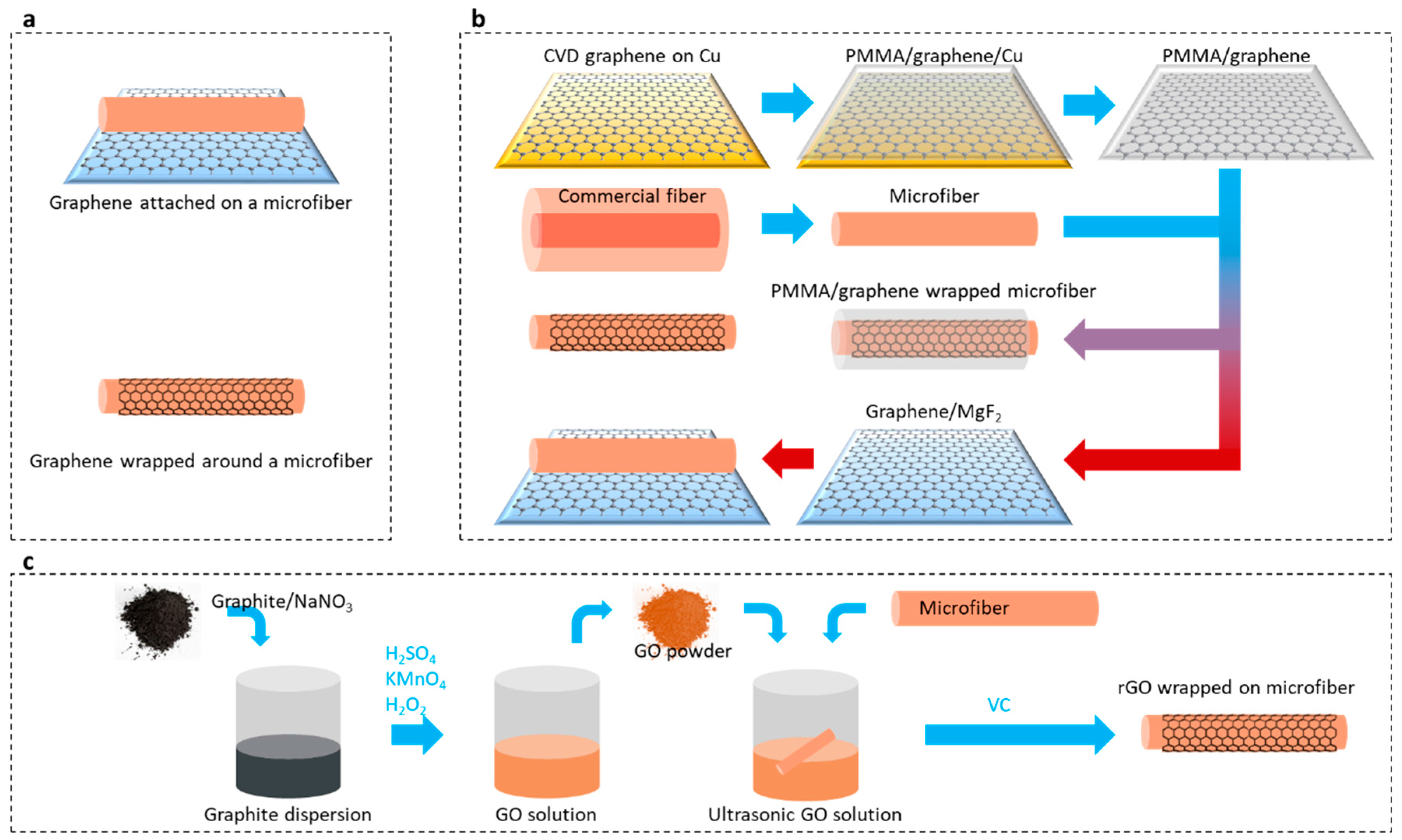
Graphene can be either attached on or wrapped around a microfiber, as schematically shown in Figure 6a. Figure 6b sketches the fabrication flows of a graphene-based fiber structure by using CVD technique [41]. For graphene attached on microfibers, graphene is transferred to a low refractive index substrate; afterwards, microfibers are put on the graphene, kept contacted. Such a van der Waals contact is firm and stable [41]. For graphene-wrapped microfibers, a substrate to carry graphene is unnecessary. The wet transfer of a CVD graphene film is done as follows: spin-coating a layer of polymethyl methacrylate (PMMA) on the surface of the graphene, forming the PMMA/graphene/Cu sandwich-like hybrid; dissolving the Cu under graphene by using FeCl3 solution; covering the PMMA/graphene flexible film on a substrate or wrapping it on a microfiber; removing the PMMA by using acetone, leaving only graphene remaining.
Figure 6c shows the process of depositing a reduced GO film on the surface of a microfiber [74]. The process involves oxidizing graphite powder to GO by using strong oxidants such as potassium permanganate; immersing a microfiber in the GO dispersion liquid; reducing the GO to be graphene by using a reductant such as vitamin C; and optimizing the film formation by controlling the temperature and the reduction time.
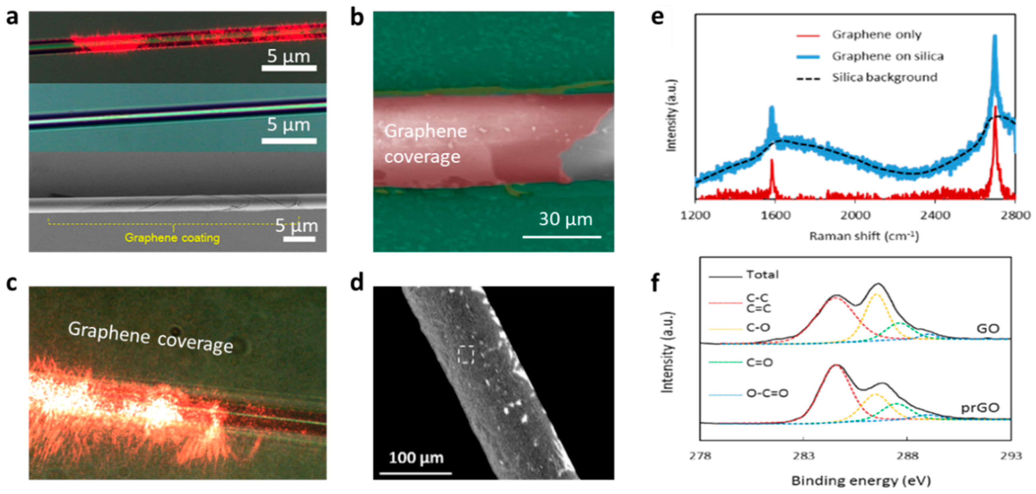
To characterize the quality of graphene on the microfibers, Raman spectroscopy [77,78,79], scanning electron microscopy (SEM), scattering measurement, and X-ray photoelectron spectroscopy (XPS) [80] are commonly applied. Figure 7a–d show the pictures of graphene-based microfibers, measured by optical microscopy and SEM. One can check the quality of the microfiber-graphene incorporation based on these images. Figure 7e plots a typical Raman spectrum of graphene on a fiber structure. Commonly, high-quality graphene on microfibers should have an ignorable D peak, and a G/2D ratio 0.3~0.5; the locations of the G peak and the 2D peak are influenced by the graphene doping. Commonly, CVD graphene is pure in chemistry, while graphene film reduced from GO may contain more functional groups, such as –OH and –COOH. These functional groups can be extremely useful for specific sensing applications; XPS is helpful to check them. Figure 7f plots the XPS of CVD graphene and reduced GO. For better deposition on microfibers, the reductions are usually controlled to make a C:O ratio > 4 [74].
4. Graphene Gas Sensors with Microfibers
In recent years, graphene gas sensors with microfibers develop rapidly, some of them are also reviewed in Refs. [81,82,83,84]. The roadmap demonstrates that the sensitivity of these graphene-based microfiber gas sensors increases from parts per kilo (ppk) to part per billion (ppb) by gradually optimizing the sensing structure.
Based on the graphene-attached microfiber scheme, we reported gas sensors based on both optical intensity detection and interferometric demodulation by using mode field analysis or Mach-Zehnder Interferometer (MZI) [52,84]. Figure 8a,b show their implementations. A microfiber with a length of several centimeters and ≈1 µm diameter was used to couple light interacting with graphene. Such a scheme is similar to a graphene-based D-shaped fiber [85,86], but is easier to manipulate. In Ref. [84], we illustrated that the polarization-dependent transmission of the graphene-attached microfiber was sensitive to gas adsorptions, especially large molecules. As Figure 8c shows, the adsorption of acetone gas molecules would dramatically dampen the optical transmission; for example, for acetone gas with a concentration of 1150 ppm, the transmission loss increased over 3 dB, the maximum sensitivity of this structure was about 0.3 dB/ppk.
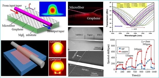
The regeneration time for the acetone gas detection was in the rage of several minutes. The interferometer scheme was a big step forward to achieve a much higher sensitivity. Figure 8d shows the performance of the graphene-microfiber-based MZI for NH3 gas detection [52]. It illustrated both high sensitivity and fast response. For NH3 trace detection, 0.3 ppm resolution and 0.5 s response delay was achieved.
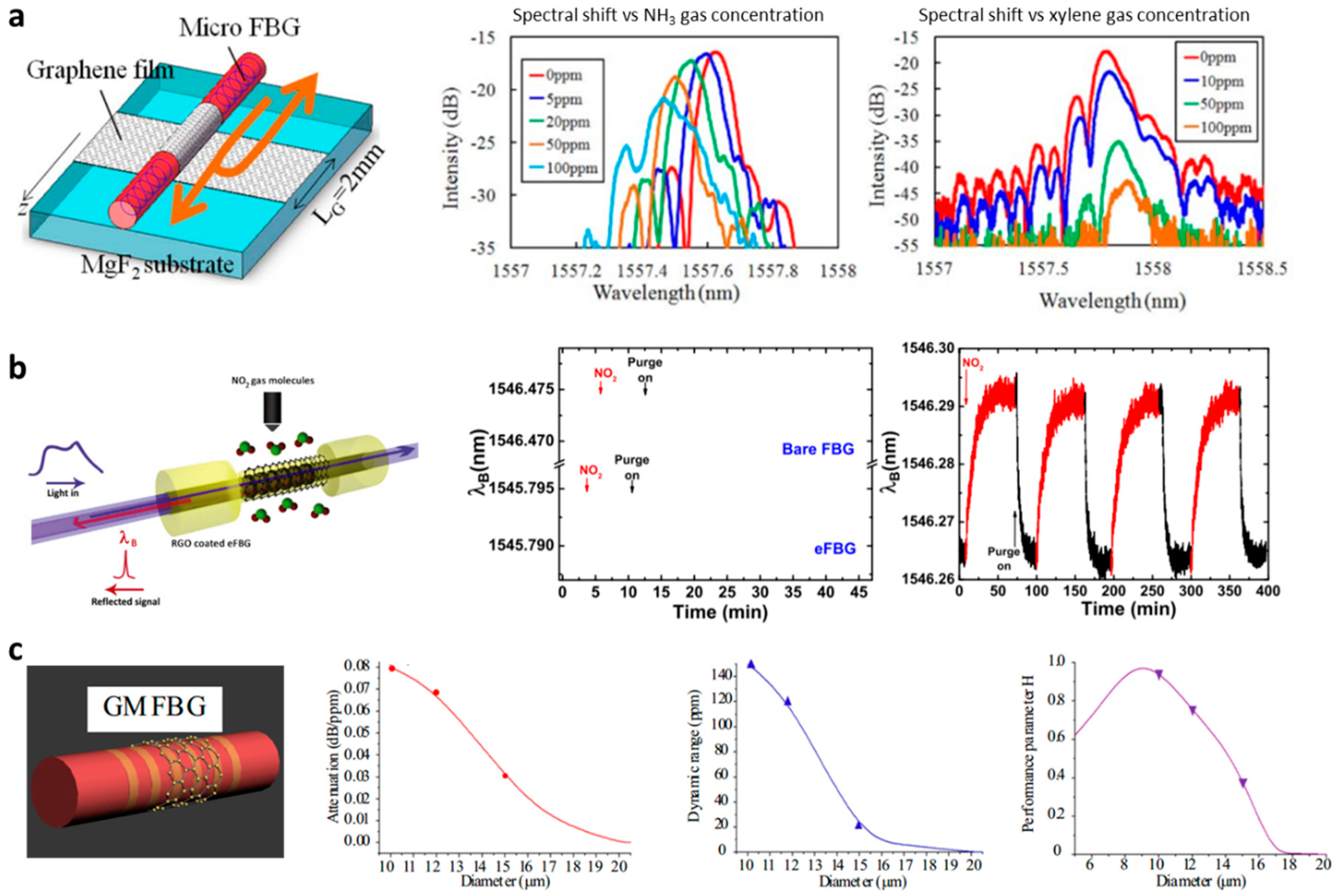
Similarly, Figure 9b shows the experimental results [87]. Sridevi et al. chose reduced GO rather than CVD graphene, getting better selectivity for NO2 gas. A sensitivity of 0.5 ppm was achieved in this work. As the reduced GO film was thicker and fluffier than the CVD graphene, its response time was limited to minute-level. In this type of sensor, it is also important to enhance the mode distribution ratio out of the core and optimize the microfiber diameter (or the thickness of the remained cladding), as discussed by Zhang et al. in Ref. [88]. Figure 9c replots the experimental results: a larger microfiber diameter brought lower sensitivity, but also lower attenuation and larger dynamic range. Considering a composite index H ~ ln(S)ln(D)/A, the best diameter could be around 10 µm for graphene-wrapped silica fiber-Bragg-gratings (FBGs) with standard 8 µm core.
Since the scheme of graphene-microfiber attachment spatially limits the light–graphene interaction, since 2014, graphene-wrapped microfiber structures have become a trend. For instance, based on graphene-wrapped micro fiber Bragg gratings (MFBGs), the footprint of the sensors can be dramatically miniaturized. Wu et al. [89] and Sridevi et al. [87] reported ultrasensitive sensors based on MFBGs for NH3 gas sensing and NO2 gas sensing, respectively. As shown in Figure 9a, Wu et al. covered a monolayer of graphene around a chemically etched MFBG. The reflection peak of the MFBG was determined by the equation λp = 2neffΛ, where Λ is the MFBG period. The gas adsorption based on neff modulation was measured by detecting the spectral shift of the MFBG. The maximum sensitivity of the CVD graphene-coated MFBG reached 0.2 ppm for NH3 gas and 0.5 ppm for xylene gas, respectively.
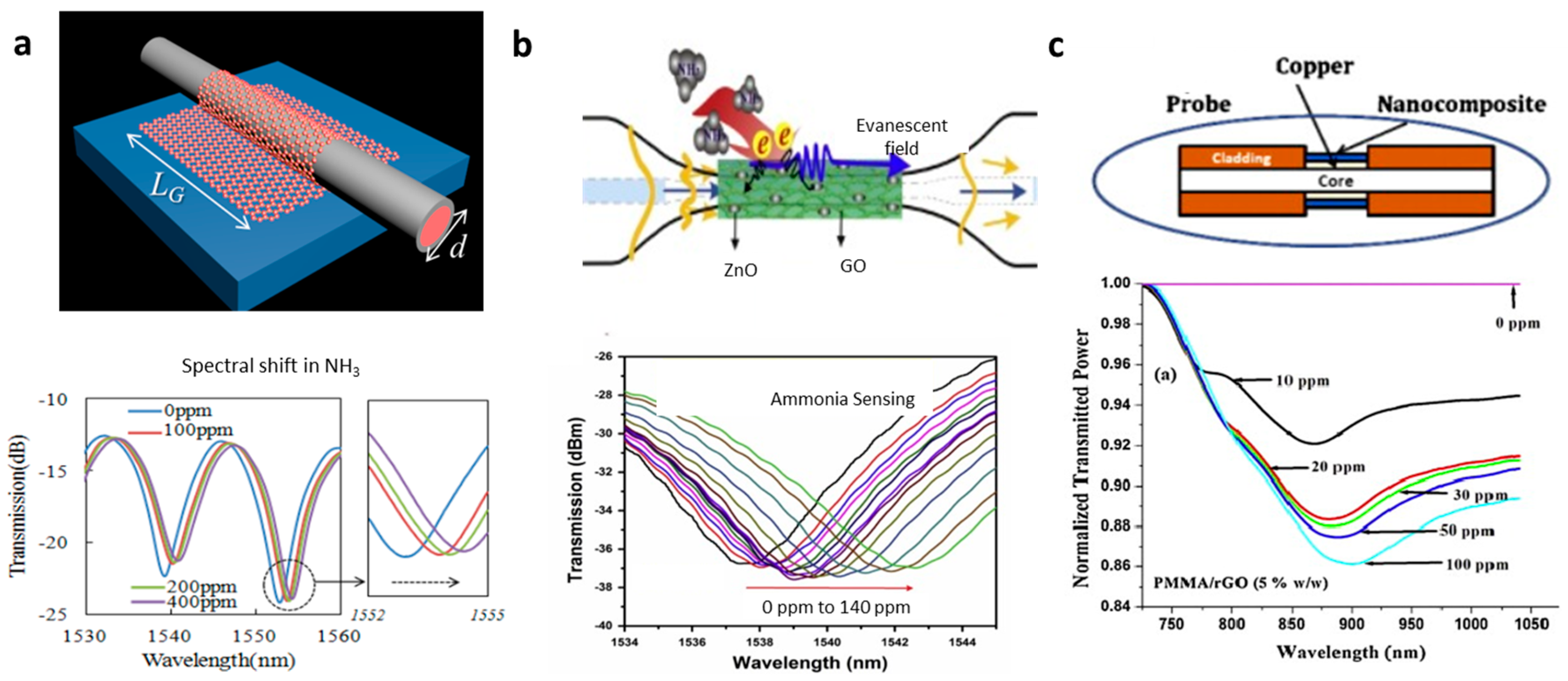
Another method to enhance light–graphene interaction in graphene-based microfiber structures is to excite high-order mode propagation with larger mode-field area or to excite plasmons. In 2014, Yao et al. demonstrated a graphene-based microfiber multimode interferometer, as shown in Figure 10a [46]. In this structure, the HE21 mode is more sensitive to local refractive index alteration than the in-core HE11 [90], hence its interference Free Spectrum Range (FSR) could be tuned by gas adsorption, resulting in a spectral resonance dip shift. In a sensing experiment, ~0.1 ppm for NH3 gas detection and ~0.2 ppm for H2O vapor detection were achieved. By using GO-ZnO film, Hu et al. also recently realized a NH3 gas sensor, demonstrating sub-ppm sensitivity, as shown in Figure 10b [91]. This GO-ZnO incorporated interferometric optical microfiber illustrated very high selectivity to NH3 gas. Additionally, in 2014, Mishra et al. also reported a graphene Surface Plasma Resonance (SPR) sensor based on microfibers for sensing NH3 gas [92]. Mishra et al. applied PMMA/graphene/Cu hybrid membrane directly to enhance the plasmons on Cu and the gas adsorption on the surface of the PMMA/graphene. It demonstrated both good sensitivity (ppm level) and relatively large dynamic range (hundreds of ppm).
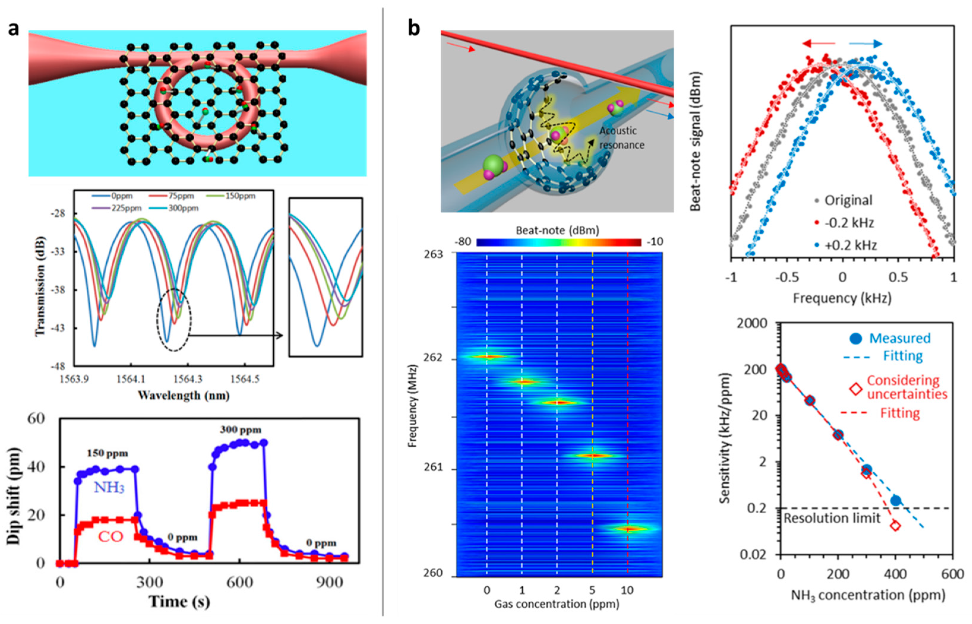
Limited by the spectral resolution of the optical interference and the linear loss of the passive devices, sub-ppm seemed to be the limitation for a graphene-based microfiber gas sensor. Taking advantage of high Q resonance, the interferometric resolution can be effectively improved. Yu et al. made such an attempt by building a GO-deposited microfiber knot resonator [93]. Figure 11a shows the structural diagram. In this study, the GO film covered the whole microfiber resonator, limiting the Q factor. In future investigations, by optimizing the graphene coverage region [94], the resolution and detection limit can potentially be further improved.
Moreover, in 2017, based on graphene-enhanced Brillouin scattering, a microfiber interrogated Whispering Gallery Mode ptomechanical gas sensor was realized. Figure 11b shows the design and the sensing performance. It reported an unprecedented high sensitivity (1 ppb) for NH3 gas detection, which is a globally leading number comparable to other advanced techniques [95,96]. Such a remarkable breakthrough revealed the “electron–phonon–photon” interaction in the graphene-based optomechanical resonator, going beyond all the conventional graphene-based optical or solid-state sensors. Optomechanical resonance was generated via Brillouin phase matching and nonlinear gain:
where vA is the acoustic velocity, c is the light velocity in vacuum, np and ns are the effective indexes of the pump mode and the generated Stokes mode, fp and fs are the pump frequency and the Stokes frequency, γe is the electro-strictive coefficient, and ΓB is the lifespan of the phonons. Gas adsorption on the reduced GO film enables an RF spectral shift 200 kHz/ppm, while the uncertainty of the Brillouin optomechanical generation is only 200 Hz, due to the extremely high Q factor (106). Moreover, such an optomechanical micro-resonator kept an exceptional dynamic range from 1 ppb to 400 ppm, crossing over five orders.
The above review summarizes the progress in optical graphene gas sensors based on microfibers. By optimizing the optical sensing structures, this type of sensor has made significant advancements in sensitivity, which is summarized in Table 1. Benefitting from the advancements in novel optical detection methods, the current performance of microfiber-based optical graphene gas sensors has been comparable to the state-of-the-art gas detection techniques, as displayed in Table 2.
5. Conclusions and Outlook
In this article, we review the principles, fabrications, implementations, and performances of optical graphene gas sensors with microfibers, which have attracted intense interest in research and development and play an important role in industry. The mode of “graphene and microfiber” has become a widely used platform for—but not limited to—gas detections. In this way, higher sensitivity and better selectivity are constant pursuits, while still remaining challenges. On one hand, to increase the sensitivity, more and more new optical mechanisms and techniques are being reported, such as graphene-based laser sensing [98], high-order nonlinearity-based enhancement [42], and plasmonic sensing in the Mid-Infrared Range to THz region [20]. On the other hand, determined by the graphene’s nature that it can interact with any gas molecule, most of the above optical gas sensors are focused on polar gas sensing, such as NH3, H2O, or NO2, and these sensors lack selectivity. Towards the realization of graphene-based microfiber sensors for other gas detection, the graphene material itself would be further functionalized, such as by using element-doped films [99], graphene grains [100], or fluorescent resonance energy transformation technology [74]. With the progress in both the microfibers and graphene materials, there is no doubt that more graphene-based fiber-optic gas sensing structures and devices can be foreseen to meet the practical application requirements.
Acknowledgments
This work was supported by the National Natural Science Foundation of China (NSFC) under Grants 61290312 and 61475032. It was also supported by the Program for Changjiang Scholars and Innovative Research Team in University (PCSIRT, IRT1218), and the 111 Project (B14039).
Conflicts of Interest
The authors declare no conflict of interest.
References
- Tong, L.; Gattass, R.R.; Ashcom, J.B.; He, S.; Lou, J.; Shen, M.; Maxwell, I.; Mazur, E. Subwavelength-diameter silica wires for low-loss optical wave guiding. Nature 2003, 426, 816–819. [Google Scholar] [CrossRef] [PubMed]
- Brambilla, G.; Xu, F.; Horak, P.; Jung, Y.; Koizumi, F.; Sessions, N.P.; Koukharenko, E.; Feng, X.; Murugan, G.S.; Wilkinson, J.S.; et al. Optical fiber nanowires and microwires: Fabrication and applications. Adv. Opt. Photonics 2009, 1, 107–161. [Google Scholar] [CrossRef]
- Tong, L.; Zi, F.; Guo, X.; Lou, J. Optical microfibers and nanofibers: A tutorial. Opt. Commun. 2012, 285, 4641–4647. [Google Scholar] [CrossRef]
- Brambilla, G. Optical fibre nanowires and microwires: A review. J. Opt. 2010, 12, 43001. [Google Scholar]
- Lou, J.; Wang, Y.; Tong, L. Microfiber Optical Sensors: A Review. Sensors 2014, 14, 5823–5844. [Google Scholar] [CrossRef] [PubMed]
- Zhang, L.; Lou, J.; Tong, L. Micro/nanofiber optical sensors. Photonic Sens. 2011, 1, 31–42. [Google Scholar] [CrossRef]
- Novoselov, K.S. Electric Field Effect in Atomically Thin Carbon Films. Science 2004, 306, 666–669. [Google Scholar] [CrossRef] [PubMed]
- Geim, A.K.; Novoselov, K.S. The rise of graphene. Nat. Mater. 2007, 6, 183–191. [Google Scholar] [CrossRef] [PubMed]
- Geim, A.K. Graphene: Status and Prospects. Science 2009, 324, 1530–1534. [Google Scholar] [CrossRef] [PubMed]
- Allen, M.J.; Tung, V.C.; Kaner, R.B. Honeycomb Carbon: A Review of Graphene. Chem. Rev. 2010, 110, 132–145. [Google Scholar] [CrossRef] [PubMed]
- Bonaccorso, F.; Sun, Z.; Hasan, T.; Ferrari, A.C. Graphene photonics and optoelectronics. Nat. Photonics 2010, 4, 611–622. [Google Scholar] [CrossRef]
- Young, R.J.; Kinloch, I.A.; Gong, L.; Novoselov, K.S. The mechanics of graphene nanocomposites: A review. Compos. Sci. Technol. 2012, 72, 1459–1476. [Google Scholar] [CrossRef]
- Balandin, A.A.; Ghosh, S.; Bao, W.; Calizo, I.; Teweldebrhan, D.; Miao, F.; Lau, C.N. Superior Thermal Conductivity of Single-Layer Graphene. Nano Lett. 2008, 8, 902–907. [Google Scholar] [CrossRef] [PubMed]
- Garcia de Abajo, F.J. Graphene Nanophotonics. Science 2013, 339, 917–918. [Google Scholar] [CrossRef] [PubMed]
- Zhang, Y.; Tan, Y.-W.; Stormer, H.L.; Kim, P. Experimental observation of the quantum Hall effect and Berry’s phase in graphene. Nature 2005, 438, 201–204. [Google Scholar] [CrossRef] [PubMed]
- Katsnelson, M.I.; Novoselov, K.S.; Geim, A.K. Chiral tunnelling and the Klein paradox in graphene. Nat. Phys. 2006, 2, 620–625. [Google Scholar] [CrossRef] [Green Version]
- Nair, R.R.; Blake, P.; Grigorenko, A.N.; Novoselov, K.S.; Booth, T.J.; Stauber, T.; Peres, N.M.R.; Geim, A.K. Fine Structure Constant Defines Visual Transparency of Graphene. Science 2008, 320, 1308. [Google Scholar] [CrossRef] [PubMed]
- Das, A.; Pisana, S.; Chakraborty, B.; Piscanec, S.; Saha, S.K.; Waghmare, U.V.; Novoselov, K.S.; Krishnamurthy, H.R.; Geim, A.K.; Ferrari, A.C.; et al. Monitoring dopants by Raman scattering in an electrochemically top-gated graphene transistor. Nat. Nanotechnol. 2008, 3, 210–215. [Google Scholar] [CrossRef] [PubMed]
- Schwierz, F. Graphene transistors. Nat. Nanotechnol. 2010, 5, 487–496. [Google Scholar] [CrossRef] [PubMed]
- Rodrigo, D.; Limaj, O.; Janner, D.; Etezadi, D.; Garcia de Abajo, F.J.; Pruneri, V.; Altug, H. Mid-infrared plasmonic biosensing with graphene. Science 2015, 349, 165–168. [Google Scholar] [CrossRef] [PubMed]
- Grigorenko, A.N.; Polini, M.; Novoselov, K.S. Graphene plasmonics. Nat. Photonics 2012, 6, 749–758. [Google Scholar] [CrossRef]
- Novoselov, K.S.; Fal′ko, V.I.; Colombo, L.; Gellert, P.R.; Schwab, M.G.; Kim, K. A roadmap for graphene. Nature 2012, 490, 192–200. [Google Scholar] [CrossRef] [PubMed]
- Sun, Z.; Martinez, A.; Wang, F. Optical modulators with 2D layered materials. Nat. Photonics 2016, 10, 227–238. [Google Scholar] [CrossRef]
- Martinez, A.; Sun, Z. Nanotube and graphene saturable absorbers for fibre lasers. Nat. Photonics 2013, 7, 842–845. [Google Scholar] [CrossRef]
- Mueller, T.; Xia, F.; Avouris, P. Graphene photodetectors for high-speed optical communications. Nat. Photonics 2010, 4, 297–301. [Google Scholar] [CrossRef]
- Hill, E.W.; Vijayaragahvan, A.; Novoselov, K. Graphene Sensors. IEEE Sens. J. 2011, 11, 3161–3170. [Google Scholar] [CrossRef]
- Liu, Y.; Dong, X.; Chen, P. Biological and chemical sensors based on graphene materials. Chem. Soc. Rev. 2012, 41, 2283–2307. [Google Scholar] [CrossRef] [PubMed]
- Yavari, F.; Koratkar, N. Graphene-Based Chemical Sensors. J. Phys. Chem. Lett. 2012, 3, 1746–1753. [Google Scholar] [CrossRef] [PubMed]
- Loh, K.P.; Bao, Q.; Eda, G.; Chhowalla, M. Graphene oxide as a chemically tunable platform for optical applications. Nat. Chem. 2010, 2, 1015–1024. [Google Scholar] [CrossRef] [PubMed]
- Schedin, F.; Geim, A.K.; Morozov, S.V.; Hill, E.W.; Blake, P.; Katsnelson, M.I.; Novoselov, K.S. Detection of individual gas molecules adsorbed on graphene. Nat. Mater. 2007, 6, 652–655. [Google Scholar] [CrossRef] [PubMed] [Green Version]
- An, B.W.; Shin, J.H.; Kim, S.-Y.; Kim, J.; Ji, S.; Park, J.; Lee, Y.; Jang, J.; Park, Y.-G.; Cho, E.; et al. Smart Sensor Systems for Wearable Electronic Devices. Polymers 2017, 9, 303. [Google Scholar] [CrossRef]
- Kim, J.; Kim, M.; Lee, M.-S.; Kim, K.; Ji, S.; Kim, Y.-T.; Park, J.; Na, K.; Bae, K.-H.; Kyun Kim, H.; et al. Wearable smart sensor systems integrated on soft contact lenses for wireless ocular diagnostics. Nat. Commun. 2017, 8, 14997. [Google Scholar] [CrossRef] [PubMed]
- Kim, Y.H.; Kim, S.J.; Kim, Y.-J.; Shim, Y.-S.; Kim, S.Y.; Hong, B.H.; Jang, H.W. Self-Activated Transparent All-Graphene Gas Sensor with Endurance to Humidity and Mechanical Bending. ACS Nano 2015, 9, 10453–10460. [Google Scholar] [CrossRef] [PubMed]
- Matko, V. Next Generation AT-Cut Quartz Crystal Sensing Devices. Sensors 2011, 11, 4474–4482. [Google Scholar] [CrossRef] [PubMed]
- Matko, V.; Milanović, M. Temperature-compensated capacitance–frequency converter with high resolution. Sen. Actuators A Phys. 2014, 220, 262–269. [Google Scholar] [CrossRef]
- Castro Neto, A.H.; Guinea, F.; Peres, N.M.R.; Novoselov, K.S.; Geim, A.K. The electronic properties of graphene. Rev. Mod. Phys. 2009, 81, 109–162. [Google Scholar] [CrossRef] [Green Version]
- Semenoff, G.W. Condensed-Matter Simulation of a Three-Dimensional Anomaly. Phys. Rev. Lett. 1984, 53, 2449–2452. [Google Scholar] [CrossRef]
- Mikhailov, S.A.; Ziegler, K. New Electromagnetic Mode in Graphene. Phys. Rev. Lett. 2007, 99, 016803. [Google Scholar] [CrossRef] [PubMed]
- Sun, Z.; Hasan, T.; Torrisi, F.; Popa, D.; Privitera, G.; Wang, F.; Bonaccorso, F.; Basko, D.M.; Ferrari, A.C. Graphene Mode-Locked Ultrafast Laser. ACS Nano 2010, 4, 803–810. [Google Scholar] [CrossRef] [PubMed]
- Yang, L.; Pei, C.; Shen, A.; Zhao, C.; Li, Y.; Li, X.; Yu, H.; Li, Y.; Jiang, X.; Yang, J. An all-optical modulation method in sub-micron scale. Sci. Rep. 2015, 5, 9206. [Google Scholar] [CrossRef] [PubMed]
- Yao, B.; Wu, Y.; Wang, Z.; Cheng, Y.; Rao, Y.; Gong, Y.; Chen, Y.; Li, Y. Demonstration of complex refractive index of graphene waveguide by microfiber-based Mach–Zehnder interferometer. Opt. Express 2013, 21, 29818. [Google Scholar] [CrossRef] [PubMed]
- Yao, B.; Liu, Y.; Huang, S.-W.; Choi, C.; Xie, Z.; Flor Flores, J.; Wu, Y.; Yu, M.; Kwong, D.-L.; Huang, Y.; et al. Broadband gate-tunable terahertz plasmons in graphene heterostructures. Nat. Photonics 2018, 12, 22–28. [Google Scholar] [CrossRef]
- Yao, B.C.; Wu, Y.; Zhang, A.Q.; Wang, F.; Rao, Y.J.; Gong, Y.; Zhang, W.L.; Wang, Z.G.; Chiang, K.S.; Sumetsky, M. Graphene Bragg gratings on microfiber. Opt. Express 2014, 22, 23829. [Google Scholar] [CrossRef] [PubMed]
- Wu, Y.; Yao, B.; Cheng, Y.; Rao, Y.; Gong, Y.; Zhou, X.; Wu, B.; Chiang, K.S. Four-wave mixing in a microfiber attached onto a graphene film. IEEE Photonics Technol. Lett. 2014, 26, 249–252. [Google Scholar] [CrossRef]
- Li, W.; Chen, B.; Meng, C.; Fang, W.; Xiao, Y.; Li, X.; Hu, Z.; Xu, Y. Ultrafast All-Optical Graphene Modulator. Nano Lett. 2014, 14, 955–959. [Google Scholar] [CrossRef] [PubMed]
- Yao, B.C.; Wu, Y.; Zhang, A.Q.; Rao, Y.J.; Wang, Z.G.; Cheng, Y.; Gong, Y.; Zhang, W.L.; Chen, Y.F.; Chiang, K.S. Graphene enhanced evanescent field in microfiber multimode interferometer for highly sensitive gas sensing. Opt. Express 2014, 22, 28154. [Google Scholar] [CrossRef] [PubMed]
- Liu, M.; Yin, X.; Ulin-Avila, E.; Geng, B.; Zentgraf, T.; Ju, L.; Wang, F.; Zhang, X. A graphene-based broadband optical modulator. Nature 2011, 474, 64–67. [Google Scholar] [CrossRef] [PubMed]
- Sorianello, V.; Midrio, M.; Contestabile, G.; Asselberg, I.; Van Campenhout, J.; Huyghebaerts, C.; Goykhman, I.; Ott, A.K.; Ferrari, A.C.; Romagnoli, M. Graphene Phase Modulator. arXiv, 2017; arXiv:1704.01525. [Google Scholar]
- Tong, L.; Lou, J.; Mazur, E. Single-mode guiding properties of subwavelength-diameter silica and silicon wire waveguides. Opt. Express 2004, 12, 1025. [Google Scholar] [CrossRef] [PubMed]
- Wu, Y.; Yao, B.C.; Feng, Q.Y.; Cao, X.L.; Zhou, X.Y.; Rao, Y.J.; Gong, Y.; Zhang, W.L.; Wang, Z.G.; Chen, Y.F.; et al. Generation of cascaded four-wave-mixing with graphene-coated microfiber. Photonics Res. 2015, 3, 64–68. [Google Scholar] [CrossRef]
- Saffarzadeh, A. Modeling of gas adsorption on graphene nanoribbons. J. Appl. Phys. 2010, 107, 114309. [Google Scholar] [CrossRef]
- Yao, B.; Wu, Y.; Cheng, Y.; Zhang, A.; Gong, Y.; Rao, Y.J.; Wang, Z.; Chen, Y. All-optical Mach-Zehnder interferometric NH3 gas sensor based on graphene/microfiber hybrid waveguide. Sens. Actuators B Chem. 2014, 194, 142–148. [Google Scholar] [CrossRef]
- Yao, B.; Yu, C.; Wu, Y.; Huang, S.-W.; Wu, H.; Gong, Y.; Chen, Y.; Li, Y.; Wong, C.W.; Fan, X.; et al. Graphene-Enhanced Brillouin Optomechanical Microresonator for Ultrasensitive Gas Detection. Nano Lett. 2017, 17, 4996–5002. [Google Scholar] [CrossRef] [PubMed]
- Basu, S.; Bhattacharyya, P. Recent developments on graphene and graphene oxide based solid state gas sensors. Sens. Actuators B Chem. 2012, 173, 1–21. [Google Scholar] [CrossRef]
- Szczęśniak, B.; Choma, J.; Jaroniec, M. Gas adsorption properties of graphene-based materials. Adv. Colloid Interface Sci. 2017, 243, 46–59. [Google Scholar] [CrossRef] [PubMed]
- Russo, P.A.; Donato, N.; Leonardi, S.G.; Baek, S.; Conte, D.E.; Neri, G.; Pinna, N. Room-Temperature Hydrogen Sensing with Heteronanostructures Based on Reduced Graphene Oxide and Tin Oxide. Angew. Chem. Int. Ed. 2012, 51, 11053–11057. [Google Scholar] [CrossRef] [PubMed]
- Yao, B.-C.; Wu, Y.; Chen, Y.; Liu, X.-P.; Gong, Y.; Rao, Y.-J. Graphene-based microfiber gas sensor. In Proceedings of the OFS2012 22nd International Conference on Optical Fiber Sensor, Beijing, China, 17 October 2012; Volume 8421. [Google Scholar] [CrossRef]
- Brambilla, G.; Finazzi, V.; Richardson, D.J. Ultra-low-loss optical fiber nanotapers. Opt. Express 2004, 12, 2258–2263. [Google Scholar] [CrossRef] [PubMed]
- Dimmick, T.E.; Kakarantzas, G.; Birks, T.A.; Russell, P.S.J. Carbon dioxide laser fabrication of fused-fiber couplers and tapers. Appl. Opt. 1999, 38, 6845–6848. [Google Scholar] [CrossRef] [PubMed]
- Pal, P.; Knox, W.H. Low loss fusion splicing of micron scale silica fibers. Opt. Express 2008, 16, 11568–11573. [Google Scholar] [CrossRef] [PubMed]
- Xu, Y.; Fang, W.; Tong, L. Real-time control of micro/nanofiber waist diameter with ultrahigh accuracy and precision. Opt. Express 2017, 25, 10434–10440. [Google Scholar] [CrossRef] [PubMed]
- Meng, C.; Xiao, Y.; Wang, P.; Zhang, L.; Liu, Y.; Tong, L. Quantum-dot-doped polymer nanofibers for optical sensing. Adv. Mater. 2011, 23, 3770–3774. [Google Scholar] [CrossRef] [PubMed]
- Meng, C.; Yu, S.-L.; Wang, H.-Q.; Cao, Y.; Tong, L.-M.; Liu, W.-T.; Shen, Y.-R. Graphene-doped polymer nanofibers for low-threshold nonlinear optical waveguiding. Light Sci. Appl. 2015, 4, e348. [Google Scholar] [CrossRef]
- Yang, P.; Yan, H.; Mao, S.; Russo, R.; Johnson, J.; Saykally, R.; Morris, N.; Pham, J.; He, R.; Choi, H.J. Controlled growth of ZnO nanowires and their optical properties. Adv. Funct. Mater. 2002, 12, 323–331. [Google Scholar] [CrossRef]
- Naqshbandi, M.; Canning, J.; Gibson, B.C.; Nash, M.M.; Crossley, M.J. Room temperature self-assembly of mixed nanoparticles into photonic structures. Nat. Commun. 2012, 3, 1188. [Google Scholar] [CrossRef] [PubMed]
- Nain, A.S.; Wong, J.C.; Amon, C.; Sitti, M. Drawing suspended polymer micro-/nanofibers using glass micropipettes. Appl. Phys. Lett. 2006, 89, 1940. [Google Scholar] [CrossRef]
- Hoffmann, P.; Dutoit, B.; Salathé, R.-P. Comparison of mechanically drawn and protection layer chemically etched optical fiber tips. Ultramicroscopy 1995, 61, 165–170. [Google Scholar] [CrossRef]
- Kou, J.-L.; Ding, M.; Feng, J.; Lu, Y.-Q.; Xu, F.; Brambilla, G. Microfiber-Based Bragg Gratings for Sensing Applications: A Review. Sensors 2012, 12, 8861–8876. [Google Scholar] [CrossRef] [PubMed]
- Kim, K.S.; Zhao, Y.; Jang, H.; Lee, S.Y.; Kim, J.M.; Kim, K.S.; Ahn, J.-H.; Kim, P.; Choi, J.-Y.; Hong, B.H. Large-scale pattern growth of graphene films for stretchable transparent electrodes. Nature 2009, 457, 706–710. [Google Scholar] [CrossRef] [PubMed]
- Obraztsov, A.N. Chemical vapour deposition: Making graphene on a large scale. Nat. Nanotechnol. 2009, 4, 212–213. [Google Scholar] [CrossRef] [PubMed]
- Wang, Z.; Chen, Y.; Li, P.; Hao, X.; Liu, J.; Huang, R.; Li, Y. Flexible Graphene-Based Electroluminescent Devices. ACS Nano 2011, 5, 7149–7154. [Google Scholar] [CrossRef] [PubMed]
- Li, X.; Cai, W.; An, J.; Kim, S.; Nah, J.; Yang, D.; Piner, R.; Velamakanni, A.; Jung, I.; Tutuc, E.; et al. Large-Area Synthesis of High-Quality and Uniform Graphene Films on Copper Foils. Science 2009, 324, 1312–1314. [Google Scholar] [CrossRef] [PubMed]
- Dreyer, D.R.; Park, S.; Bielawski, C.W.; Ruoff, R.S. The chemistry of graphene oxide. Chem. Soc. Rev. 2010, 39, 228–240. [Google Scholar] [CrossRef] [PubMed]
- Yao, B.C.; Wu, Y.; Yu, C.B.; He, J.R.; Rao, Y.J.; Gong, Y.; Fu, F.; Chen, Y.F.; Li, Y.R. Partially reduced graphene oxide based FRET on fiber-optic interferometer for biochemical detection. Sci. Rep. 2016, 6, 23706. [Google Scholar] [CrossRef] [PubMed]
- Eda, G.; Fanchini, G.; Chhowalla, M. Large-area ultrathin films of reduced graphene oxide as a transparent and flexible electronic material. Nat. Nanotechnol. 2008, 3, 270–274. [Google Scholar] [CrossRef] [PubMed]
- Yao, B.C.; Rao, Y.J.; Huang, S.W.; Wu, Y.; Feng, Z.Y.; Choi, C.; Liu, H.; Qi, H.F.; Duan, X.F.; Peng, G.D.; et al. Graphene Q-switched distributed feedback fiber lasers with narrow linewidth approaching the transform limit. Opt. Express 2017, 25, 8202–8211. [Google Scholar] [CrossRef] [PubMed]
- Ferrari, A.C. Raman spectroscopy of graphene and graphite: Disorder, electron–phonon coupling, doping and nonadiabatic effects. Solid State Commun. 2007, 143, 47–57. [Google Scholar] [CrossRef]
- Caridad, J.M.; Rossella, F.; Bellani, V.; Maicas, M.; Patrini, M.; Díez, E. Effects of particle contamination and substrate interaction on the Raman response of unintentionally doped graphene. J. Appl. Phys. 2010, 108, 84321. [Google Scholar] [CrossRef]
- Caridad, J.M.; Rossella, F.; Bellani, V.; Grandi, M.S.; Diez, E. Automated detection and characterization of graphene and few-layer graphite via Raman spectroscopy. J. Raman Spectrosc. 2011, 42, 286–293. [Google Scholar] [CrossRef]
- Paton, K.R.; Varrla, E.; Backes, C.; Smith, R.J.; Khan, U.; O’Neill, A.; Boland, C.; Lotya, M.; Istrate, O.M.; King, P.; et al. Scalable production of large quantities of defect-free few-layer graphene by shear exfoliation in liquids. Nat. Mater. 2014, 13, 624–630. [Google Scholar] [CrossRef] [PubMed]
- Zhao, Y.; Li, X.; Zhou, X.; Zhang, Y. Review on the graphene based optical fiber chemical and biological sensors. Sens. Actuators B Chem. 2016, 231, 324–340. [Google Scholar] [CrossRef]
- Hernaez, M.; Zamarreño, C.; Melendi-Espina, S.; Bird, L.; Mayes, A.; Arregui, F. Optical Fibre Sensors Using Graphene-Based Materials: A Review. Sensors 2017, 17, 155. [Google Scholar] [CrossRef] [PubMed]
- Shivananju, B.N.; Yu, W.; Liu, Y.; Zhang, Y.; Lin, B.; Li, S.; Bao, Q. The Roadmap of Graphene-Based Optical Biochemical Sensors. Adv. Funct. Mater. 2017, 27, 1603918. [Google Scholar] [CrossRef]
- Wu, Y.; Yao, B.; Cheng, Y.; Rao, Y.; Gong, Y.; Zhang, W.; Wang, Z.; Chen, Y. Hybrid Graphene-Microfiber Waveguide for Chemical Gas Sensing. IEEE J. Sel. Top. Quantum Electron. 2014, 20, 4400206. [Google Scholar] [CrossRef]
- Wu, Y.; Yao, B.C.; Zhang, A.Q.; Cao, X.L.; Wang, Z.G.; Rao, Y.J.; Gong, Y.; Zhang, W.; Chen, Y.F.; Chiang, K.S. Graphene-based D-shaped fiber multicore mode interferometer for chemical gas sensing. Opt. Lett. 2014, 39, 6030–6033. [Google Scholar] [CrossRef] [PubMed]
- Yao, B.C.; Rao, Y.J.; Wang, Z.N.; Wu, Y.; Zhou, J.H.; Wu, H.; Fan, M.Q.; Cao, X.L.; Zhang, W.L.; Chen, Y.F.; et al. Graphene based widely-tunable and singly-polarized pulse generation with random fiber lasers. Sci. Rep. 2015, 5, 1–8. [Google Scholar] [CrossRef] [PubMed]
- Sridevi, S.; Vasu, K.S.; Bhat, N.; Asokan, S.; Sood, A.K. Ultra sensitive NO2 gas detection using the reduced graphene oxide coated etched fiber Bragg gratings. Sens. Actuators B Chem. 2016, 223, 481–486. [Google Scholar] [CrossRef]
- Zhang, A.; Wu, Y.; Yao, B.; Gong, Y. Optimization study on graphene-coated microfiber Bragg grating structures for ammonia gas sensing. Photonic Sens. 2014, 5, 84–90. [Google Scholar] [CrossRef]
- Wu, Y.; Yao, B.; Zhang, A.; Rao, Y.; Wang, Z.; Cheng, Y.; Gong, Y.; Zhang, W.; Chen, Y.; Chiang, K.S. Graphene-coated microfiber Bragg grating for high-sensitivity gas sensing. Opt. Lett. 2014, 39, 1235–1237. [Google Scholar] [CrossRef] [PubMed]
- Sun, Q.; Luo, H.; Luo, H.; Lai, M.; Liu, D.; Zhang, L. Multimode microfiber interferometer for dual-parameters sensing assisted by Fresnel reflection. Opt. Express 2015, 23, 12777–12783. [Google Scholar] [CrossRef] [PubMed]
- Fu, H.; Jiang, Y.; Ding, J.; Zhang, J.; Zhang, M.; Zhu, Y.; Li, H. Zinc oxide nanoparticle incorporated graphene oxide as sensing coating for interferometric optical microfiber for ammonia gas detection. Sens. Actuators B Chem. 2018, 254, 239–247. [Google Scholar] [CrossRef]
- Mishra, S.K.; Tripathi, S.N.; Choudhary, V.; Gupta, B.D. SPR based fibre optic ammonia gas sensor utilizing nanocomposite film of PMMA/reduced graphene oxide prepared by in situ polymerization. Sens. Actuators B Chem. 2014, 199, 190–200. [Google Scholar] [CrossRef]
- Yu, C.-B.; Wu, Y.; Liu, X.-L.; Yao, B.-C.; Fu, F.; Gong, Y.; Rao, Y.-J.; Chen, Y.-F. Graphene oxide deposited microfiber knot resonator for gas sensing. Opt. Mater. Express 2016, 6, 727–733. [Google Scholar] [CrossRef]
- Phare, C.T.; Daniel Lee, Y.-H.; Cardenas, J.; Lipson, M. Graphene electro-optic modulator with 30 GHz bandwidth. Nat. Photonics 2015, 9, 511–514. [Google Scholar] [CrossRef]
- Lehner, P.; Staudinger, C.; Borisov, S.M.; Klimant, I. Ultra-sensitive optical oxygen sensors for characterization of nearly anoxic systems. Nat. Commun. 2014, 5, 4460. [Google Scholar] [CrossRef] [PubMed]
- Jin, W.; Cao, Y.; Yang, F.; Ho, H.L. Ultra-sensitive all-fibre photothermal spectroscopy with large dynamic range. Nat. Commun. 2015, 6, 6767. [Google Scholar] [CrossRef] [PubMed]
- Caucheteur, C.; Guo, T.; Liu, F.; Guan, B.-O.; Albert, J. Ultrasensitive plasmonic sensing in air using optical fibre spectral combs. Nat. Commun. 2016, 7, 13371. [Google Scholar] [CrossRef] [PubMed]
- Tan, Y.; Zhang, C.; Jin, W.; Yang, F.; Lut Ho, H.; Ma, J. Optical Fiber Photoacoustic Gas Sensor with Graphene Nano-Mechanical Resonator as the Acoustic Detector. IEEE J. Sel. Top. Quantum Electron. 2017, 23, 199–209. [Google Scholar] [CrossRef]
- Jiang, G.; Goledzinowski, M.; Comeau, F.J.E.; Zarrin, H.; Lui, G.; Lenos, J.; Veileux, A.; Liu, G.; Zhang, J.; Hemmati, S.; et al. Free-Standing Functionalized Graphene Oxide Solid Electrolytes in Electrochemical Gas Sensors. Adv. Funct. Mater. 2016, 26, 1729–1736. [Google Scholar] [CrossRef]
- Ma, T.; Liu, Z.; Wen, J.; Gao, Y.; Ren, X.; Chen, H.; Jin, C.; Ma, X.-L.; Xu, N.; Cheng, H.-M.; et al. Tailoring the thermal and electrical transport properties of graphene films by grain size engineering. Nat. Commun. 2017, 8, 14486. [Google Scholar] [CrossRef] [PubMed]
Figure 1.
Optoelectronic property of graphene (a) Band structure; (b) Calculated conductivities varying in Fermi level; (c) Calculated permittivity and refractive index, in real and imaginary parts, respectively. Here (a,b) are reproduced from Refs. [36,42], respectively.
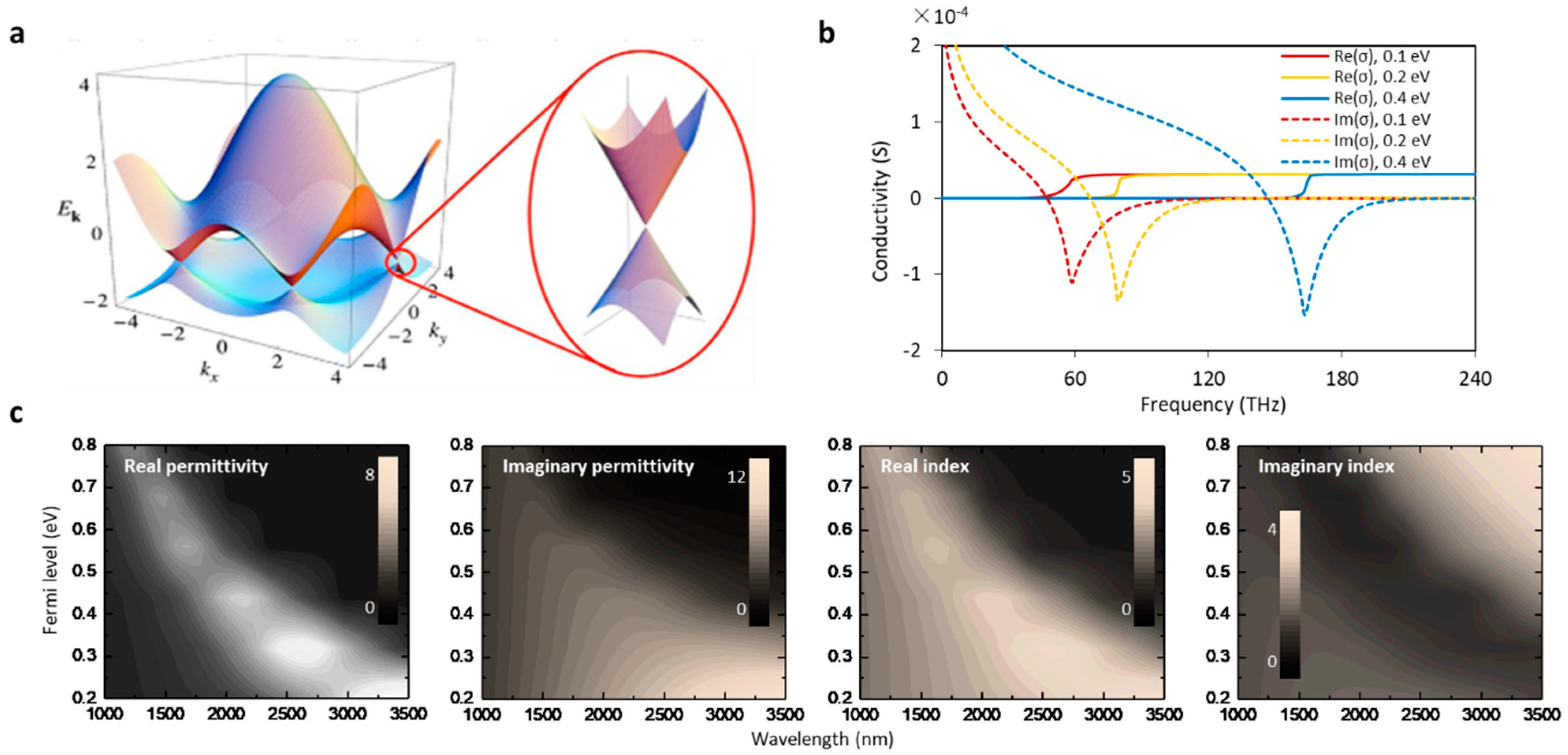
Figure 2.
Calculation and simulation of graphene-based microfibers. (a) Scheme of the finite element method (FEM) simulation for graphene-based microfibers. (b) Simulated electric field intensity distributions. (c) Calculated effective index of a graphene-based microfiber, relying on the Fermi level of graphene. Here simulations in (b) are reproduced from Refs. [43,46].

Figure 3.
Mechanism of graphene-based electric and optical gas sensors. (a) Gas molecules adsorbed on graphene. (b) Detecting gas molecules adsorbed on graphene electrically. (c) Method to detect gas molecules adsorbed on graphene optically. Here (a–d) are reproduced from Refs. [30,51,52,53], respectively.

Figure 4.
Fabrication of microfibers. (a) Pictures of silica microfibers. (b,c) Setups for fusing & drawing glass microfibers. (d) Microfibers besides glass materials. Here pictures of (a,d) are reproduced from Ref. [1] and Refs. [62,63,64,65,66], respectively.

Figure 5.
Graphene fabrication. (a) Graphene grown by using chemical vapor deposition (CVD) method. (b) Pictures of graphene samples fabricated by using CVD method. (c) Graphene reduced from graphene oxide (GO) in liquid. (d) Picture of GO and reduced GO (rGO) dispersions, and the deposited reduced GO film on silicon substrate. Pictures in (b) are reproduced from Refs. [71,72].

Figure 6.
Fabrications. (a) Two types graphene-based microfiber structure. (b) Fabrication flow of both the graphene-attached microfibers and the graphene-wrapped microfibers, based on CVD graphene. (c) Fabrication flow based on GO reduction.
Figure 6.
Fabrications. (a) Two types graphene-based microfiber structure. (b) Fabrication flow of both the graphene-attached microfibers and the graphene-wrapped microfibers, based on CVD graphene. (c) Fabrication flow based on GO reduction.

Figure 7.
Characterizations of graphene-based microfiber structures. (a) Visible scattering, optical microscope, and SEM pictures of a graphene-wrapped hot drawn microfiber. (b) A false-colored SEM picture of a graphene-wrapped microfiber etched chemically. (c) Light scattering enhancement due to the graphene. (d) SEM of an etched microfiber covered by reduced GO. (e) Raman spectra. (f) Measured X-ray photoelectron spectroscopy (XPS) results. Here figures (a–d) are reproduced from Refs. [45,46,74,76], respectively.

Figure 8.
Optical gas sensors based on graphene attached on microfibers by using (a) mode-field analysis and power metering; (b) MZI interferometer; (c) Sensing performance of the graphene-based acetone gas sensor; (d) Sensing performance of the graphene-based MZI sensor for NH3 gas detection. Here the results are reproduced from Ref. [52,84].
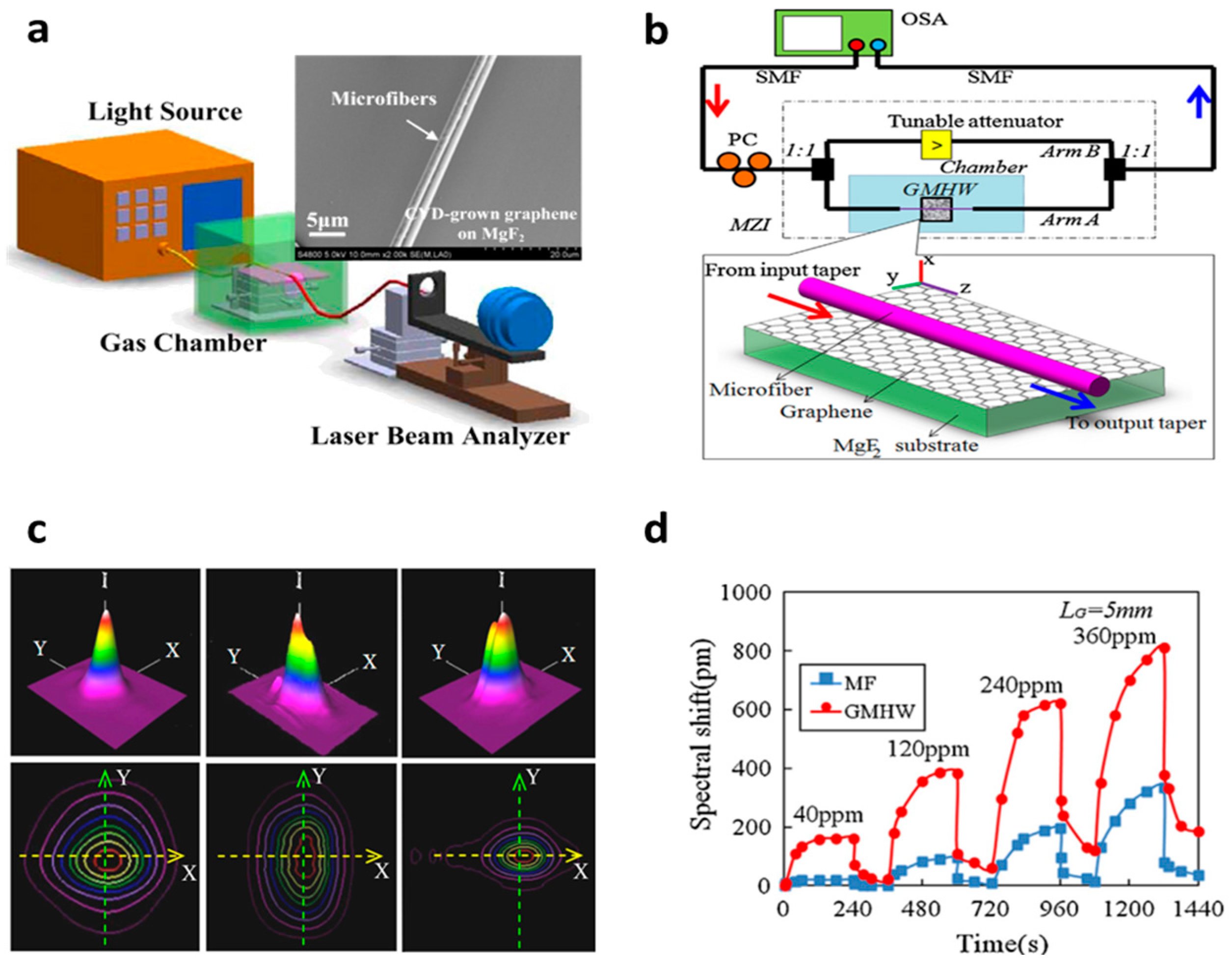
Figure 9.
Graphene-based micro fiber Bragg grating (GMFBG) gas sensors (a) for NH3 gas detection, (b) for NO2 gas detection. (c) Diameter optimization of the micro FBG gas sensors. Figures in (a–c) are reproduced from Refs. [87,88,89].

Figure 10.
Optical gas sensors based on graphene-wrapped microfiber structures. (a) NH3/H2O sensor based on CVD graphene-microfiber multimode interferometer, (b) NH3 gas sensor based on ZnO-GO-covered graphene-microfiber multimode interferometer, (c) NH3 gas sensor based on SPR on a PMMA/graphene/Cu-covered microfiber. Here the figures are reproduced from Refs. [46,91,92].

Figure 11.
Design and performance of microfiber integrated graphene gas sensors based on resonators. (a) NH3 gas sensor based on GO deposited microfiber knot, (b) NH3 gas sensor based on graphene-enhanced Brillouin optomechanics. Figures are reproduced from Ref. [53,93].


Table 1.
Major progress in the optical graphene gas sensors based on microfibers.
| Year | Sensor Structure | Target Gas | Performance | Reference |
|---|---|---|---|---|
| 2012 | Microfiber attached on graphene | Acetone | Sub-ppk sensitivity | [57] |
| 2014 | Graphene/gold coated on microfiber for SPR | NH3 | 1 ppm sensitivity | [92] |
| 2014 | Graphene-coated microfiber interferometers | NH3, H2O | Sub-ppm sensitivity Fast response | [46,89] |
| 2016 | Reduced GO coated on microfiber Bragg gratings | NO2 | 500 ppb sensitivity~100% recoverability | [87] |
| 2017 | Reduced GO-based optomechanic microresonator | NH3 | 1 ppb sensitivity five orders dynamic range | [53] |
| 2018 | ZnO-functionalized GO coated on a microfiber multimode interferometer | NH3 | Sub-ppm sensitivity High selectivity | [91] |
Table 2.
Major progress in optical graphene gas sensors based on microfibers.
| Sensor Type | Max Sensitivity | Dynamic Range | Response Time | Reference |
|---|---|---|---|---|
| Photothermal spectroscopy | 2 ppb | six orders | minutes | [96] |
| Graphene-based SPR on fiber | 1 ppm | NG | minutes | [92] |
| Ultrasensitive plasmonic sensors based on metal | ~ppm | NG | NG | [97] |
| Visible spectroscopy | 5 ppb | NG | minutes | [95] |
| Microfiber-based graphene optomechanic resonator | 1 ppb | five orders | seconds | [53] |
© 2018 by the authors. Licensee MDPI, Basel, Switzerland. This article is an open access article distributed under the terms and conditions of the Creative Commons Attribution (CC BY) license (http://creativecommons.org/licenses/by/4.0/).
Share and Cite
MDPI and ACS Style
Wu, Y.; Yao, B.; Yu, C.; Rao, Y. Optical Graphene Gas Sensors Based on Microfibers: A Review. Sensors 2018, 18, 941. https://doi.org/10.3390/s18040941
AMA Style
Wu Y, Yao B, Yu C, Rao Y. Optical Graphene Gas Sensors Based on Microfibers: A Review. Sensors. 2018; 18(4):941. https://doi.org/10.3390/s18040941
Chicago/Turabian StyleWu, Yu, Baicheng Yao, Caibin Yu, and Yunjiang Rao. 2018. "Optical Graphene Gas Sensors Based on Microfibers: A Review" Sensors 18, no. 4: 941. https://doi.org/10.3390/s18040941
Note that from the first issue of 2016, this journal uses article numbers instead of page numbers. See further details here.