Multiple Fano-Like MIM Plasmonic Structure Based on Triangular Resonator for Refractive Index Sensing


BioSense Institute-Research Institute for Information Technologies in Biosystems, University of Novi Sad, Dr Zorana Djindjica 1a, 21000 Novi Sad, Serbia
*
Author to whom correspondence should be addressed.
Sensors 2018, 18(1), 287; https://doi.org/10.3390/s18010287
Submission received: 1 December 2017
/
Revised: 19 December 2017
/
Accepted: 21 December 2017
/
Published: 19 January 2018
(This article belongs to the Section Biosensors)
Abstract
:In this paper, we present a Fano metal-insulator-metal (MIM) structure based on an isosceles triangular cavity resonator for refractive index sensing applications. Due to the specific feeding scheme and asymmetry introduced in the triangular cavity, the resonator exhibits four sharp Fano-like resonances. The behavior of the structure is analyzed in detail and its sensing capabilities demonstrated through the responses for various refractive indices. The results show that the sensor has very good sensitivity and maximal figure of merit (FOM) value of 3.2 × 10⁵. In comparison to other similar sensors, the proposed one has comparable sensitivity and significantly higher FOM, which clearly demonstrates its high sensing potential.
1. Introduction
Surface plasmon polaritons (SPP) represent electromagnetic surface waves occurring at the interface between a dielectric and conductor due to the coupling of electromagnetic fields to collective electron oscillations [1]. Due to the peculiar nature and ability to overcome the diffraction limit and confine light in sub-wavelength dimensions, SPPs have found a number of applications [2,3,4,5]. There have been different SPP guiding structures proposed such as metal nanoparticle chains, metal films, metal-insulator-metal (MIM) slabs, metal grooves, metal strips, and a hybrid Bragg waveguide, among which MIM slabs have attracted significant attention due to their suitability for highly-integrated photonic circuits and a good trade-off between the light confinement and energy loss [6]. Therefore, various devices based on MIM waveguides have been proposed, including switches [7], filters [8,9,10], sensors [11,12], splitters [13], and demultiplexer sensors [14].
When it comes to sensors, their sensitivity and figure of merit (FOM) are critical for overall performance. One of the promising solutions for sensitivity and FOM improvement is the employment of Fano resonances which exhibit an asymmetrical response with very abrupt change between transmittance peak and dip. Although originally discovered in atomic physics [15], Fano resonance has more universal character and it has also been found and used in other fields such as plasmonics, metamaterials, and photonics [16,17]. Generally, Fano resonance occurs due to the interaction between bright (radiative) and dark modes (non-radiative), i.e., between spectrally broad continuum states that can couple to the incident light, and narrow subradiant modes that cannot directly be excited by the light. Such behavior is usually obtained by the introduction of an asymmetry in the structure. However, it has been shown that Fano resonances can be also obtained through mechanisms other than classical near-field interactions and mode hybridization [18].
In MIM plasmonic structures, Fano resonances are usually realized following the classical pattern, i.e., two or three different resonators are employed, one of which effectively creates bright mode, and the other(s) dark mode(s) [19,20,21,22,23,24,25,26,27,28]. There are also structures whose Fano response is based on phase-coupling between two detuned modes of different resonators [29,30,31], interaction between the modes of two identical resonators [32,33], or between different modes of the same resonator [34,35]. In addition, there are designs in which different mechanisms are combined such as those proposed in [36,37], in which interference between different resonant modes of one resonator, the interference between the resonator’s degenerate modes, and the interference between the resonant modes of different resonators, have been employed to realize a triple-Fano response.
As for the geometry of the structures, groove resonators are widely exploited and combined with other resonators such as stub resonators [21,26,28,30], circular [22,25,26] and rectangular cavities [20], as well as with another groove [34]. Other configurations with different types of resonators include those with stub and ring resonators [27,31] and circular cavity and T-shaped waveguide [29]. Moreover, there have been proposed MIM Fano structures with two resonators of the same type such as stub resonators [19], rectangular and square cavities [23,32,36], ring resonators [24], metal strips [33], as well as those that are based on only one resonator-trapezoid cavity [35] and circular cavity [37].
Most proposed sensors have been designed to exhibit single or double Fano resonance, although multiple-Fano responses are preferable since it may provide more reliable results or even multi-sensing applications. However, the proposed multiple-Fano sensors cannot provide good sensitivity, high FOM, and high transmission level simultaneously at all resonances.
In this paper, we present a Fano MIM structure based on an isosceles triangular cavity resonator which exhibits four Fano-like resonances. The feeding lines provide a broad continuum state which is coupled to the four narrow fundamental modes of the resonator. Owing to the feeding scheme, in which the feeding lines are asymmetrically positioned with respect to the triangular resonator, the resonant modes are somewhat disturbed and exhibit asymmetrical Fano-like response rather than classical Lorentzian shape. Moreover, all four resonances exhibit sharp resonances and high transmission magnitudes, and thus the proposed structure has an excellent refractive index sensing potential with good sensitivity and high FOM, overperforming most similar structures.
In the following sections, a detailed analysis of the proposed Fano MIM sensor will be given, together with the eigenmode analysis of the triangular cavity resonator and its behavior within the MIM environment. The sensing capabilities will be demonstrated through the comparison of the responses for different values of the refractive index and the overall performance of the proposed sensor will be discussed.
2. Structure Analysis
The layout of the proposed sensor, together with the corresponding geometrical parameters are shown in Figure 1. It consists of an isosceles triangular cavity resonator with slightly disturbed lower corners, and two MIM waveguides, which are asymmetrically positioned with respect to the cavity. The white area represents air whose refractive index is equal to 1, whilst the blue area represents silver which is characterized using the Drude model [38]
where the permittivity at the infinite frequency ε∞ is equal to 3.7, plasma frequency ωp is 1.38 × 10¹⁶ rad/s, and the damping frequency γ equals 2.73 × 10¹³ Hz. The width of the MIM waveguide w has been chosen to be 50 nm to provide that only the fundamental transverse magnetic (TM0) mode is supported. The base of the triangular resonator B is equal to 600 nm, its height H 415 nm, whilst its sides S are equal to 513 nm. It should be noted that the dimensions B, H, and S are related to the full triangle as indicated by the dashed lines in Figure 1, and they are fixed throughout the paper. However, the proposed resonator somehow has disturbed corners, i.e., the lower corners are cut and thus additional dimensions have been introduced—b1 and b2—which indicate the disturbance of the triangular resonator. Also, p1 and p2 represent the distances of the central axes of the MIM waveguides from the symmetry axis and half-height point of the resonator, respectively.
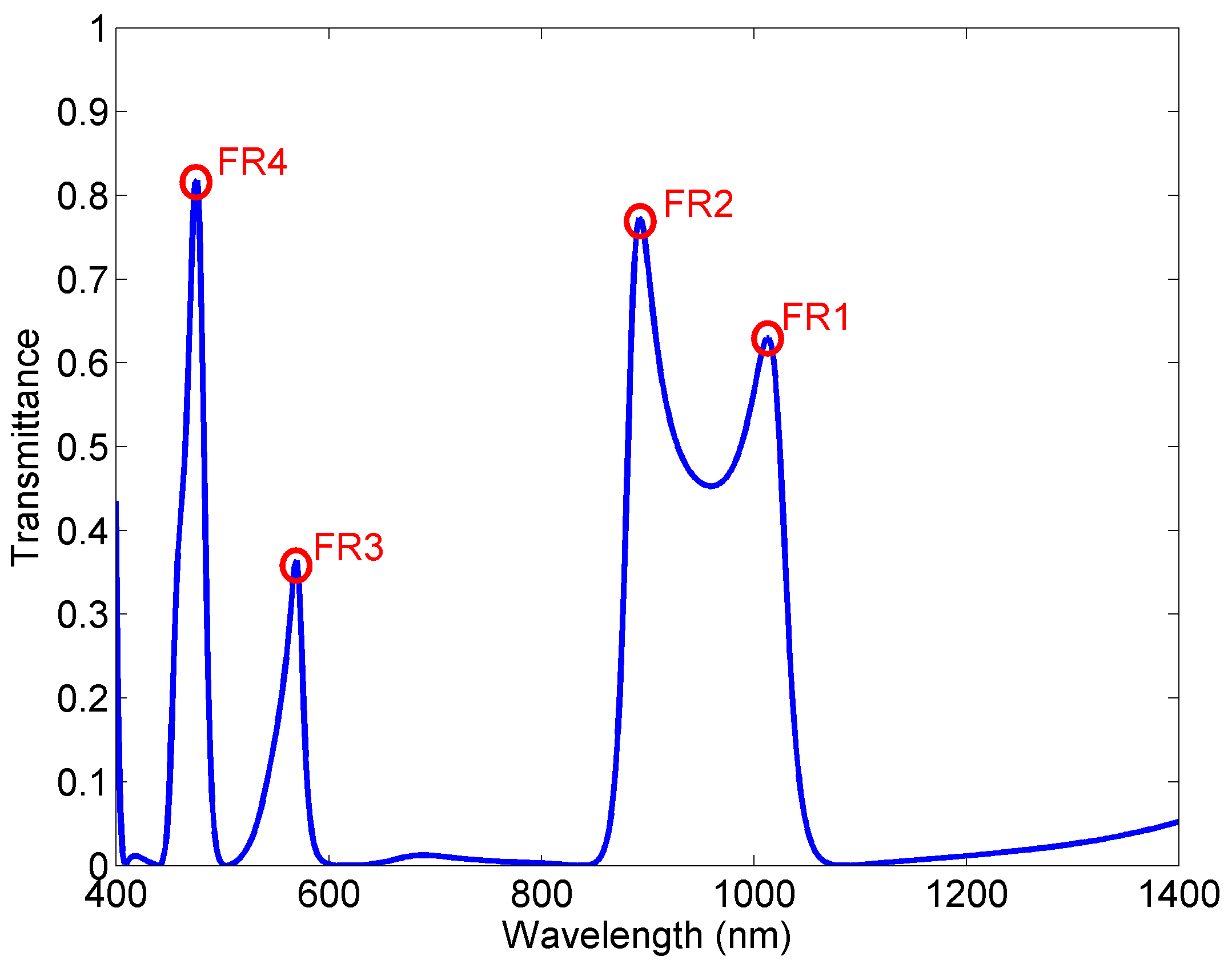
The structure’s response has been investigated using finite element method (FEM) with the Comsol Multiphysics and the transmittance of SPPs is defined as the ratio between the SPP power flows (obtained by integrating the Poynting vector over the waveguide cross section) of the port with and without triangular structure [21,22]. Figure 2 shows the transmission spectrum of the structure with the following dimensions: b1 = 50 nm, b2 = 30 nm, p1 = 30 nm, and p2 = 30 nm, and it reveals that the structure exhibits four narrow asymmetric profiles, i.e., Fano-like resonances at 1012, 892, 570, and 476 nm, marked as FR1, FR2, FR3, and FR4.
The structure can be described using multimode interference coupled mode theory (MICMT) [36,37], i.e., using the expressions
where an, ωn, and τn0 represent the field amplitude, resonant frequency, and the decay time of internal loss of the n-th resonant mode respectively. τn1 and τn2 are the decay time of the coupling between the resonator and waveguides, θn1 and θn2 are the coupling phases, and ϕ1n and ϕ2n are the complex amplitude phases of the n-th resonant mode coupled to the waveguides. si± are the field amplitudes in each waveguide (i = 1, 2, for outgoing (−) or incoming (+) from the resonator), whilst γn is the normalized coefficient which is approximated as 1.
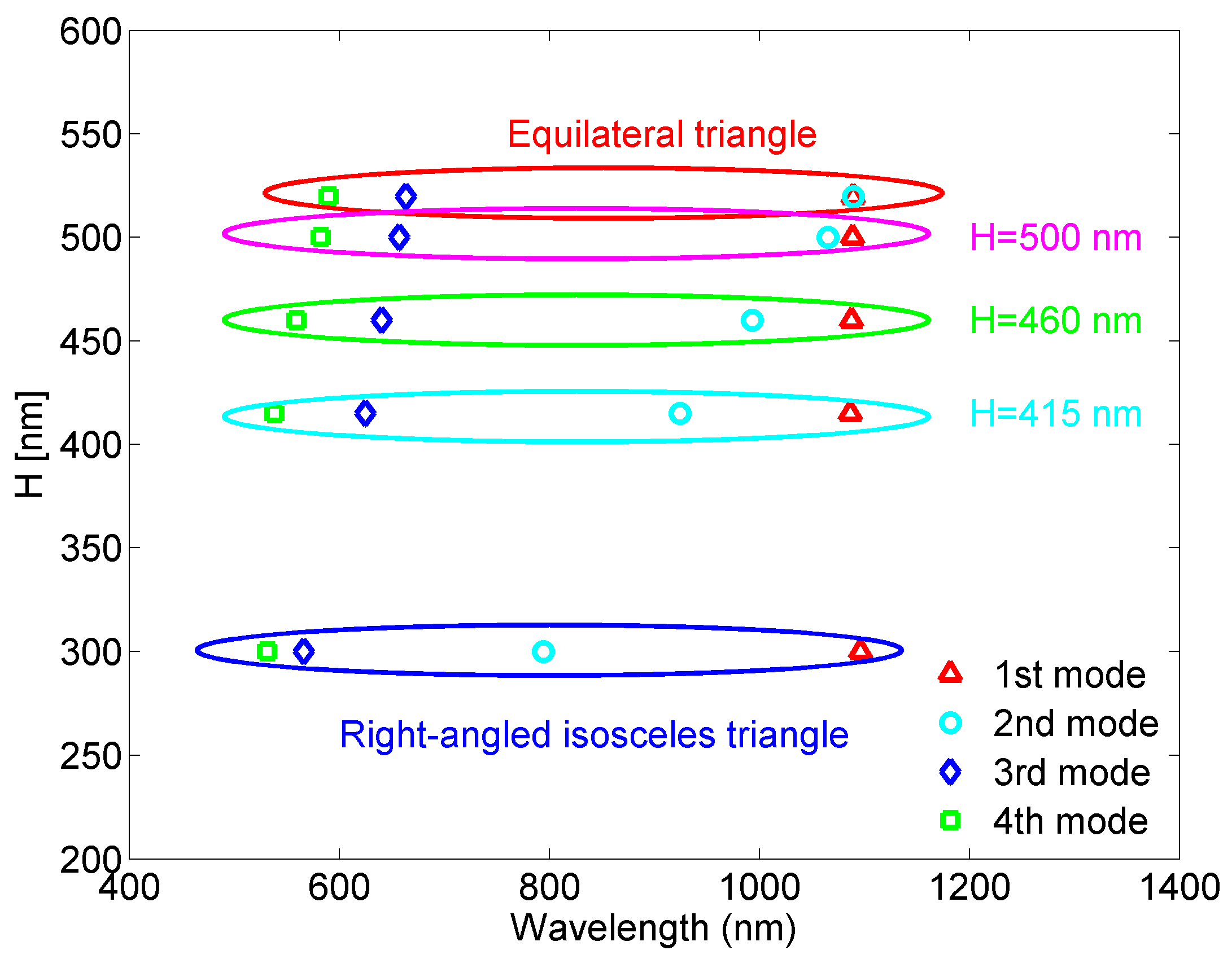
To understand the underlying idea of the proposed sensor and the nature of its response, the behavior of the triangular cavity resonator should be analyzed. Although widely used, triangular resonators have been analytically investigated practically only in the cases of equilateral or right-angled isosceles triangles, primarily due to very complex mode calculus [39,40,41]. Using numerical eigenmode analysis, the resonant wavelengths of the four lowest modes have been calculated for the equilateral triangular resonator with the side length of 600 nm, and the right-angled isosceles triangle with the base equal to 600 nm, Figure 3. One can note that in the case of equilateral triangular resonator two lowest modes have the same spectral position, and the other two are positioned at 664 and 590 nm. On the other hand, the right-angled isosceles triangular resonator exhibits two lowest modes that are relatively distant, and two higher modes that are very closely positioned. Thus, the two triangular cavities are not preferable choices if multiple resonances with even spectral distribution are desired.
To provide more than three resonant modes, which are evenly positioned in the spectrum, we have modified the equilateral triangular resonator in terms of its height, i.e., it has been transformed into isosceles triangle which is not however right-angled. Figure 3 also shows how the resonant wavelengths change with the triangle height and it can be seen that more even modes’ distribution can be obtained in the case of isosceles triangular resonator, which is more appropriate for multiple-sensing applications. For further investigation, we chose the structure whose height is equal to 415 nm.
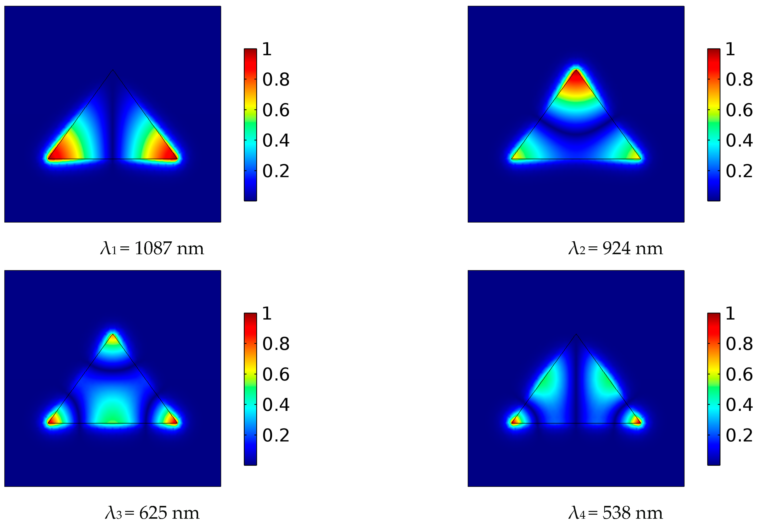
In order to further understand the nature of the proposed structure, numerical eigenmode analysis of the fully symmetrical isosceles triangular cavity with H = 415 nm has been performed and Figure 4 shows normalized Hz field distribution of the four lowest fundamental modes.
To achieve Fano-like response at four fundamental modes, we have introduced asymmetry in the structure primarily through the specific position of the MIM waveguides. Namely, feeding positions have not been mirrored with respect to the triangle symmetry axis, but they have been judiciously chosen in a manner that one MIM waveguide is positioned at the point of sufficiently strong field of a mode, and the other at the point of zero or very weak field of the mode. Such an asymmetrical feeding scheme provides that a mode is simultaneously strongly and weakly excited, and consequently transmission peak and transmission dip occur very closely in the spectrum.
Taking into consideration this concept and the field distribution of the four modes, the MIM waveguides have been positioned as shown in Figure 1, since this allows the previously described phenomenon to occur at all four modes. One should note that this would not be possible in case of rectangular or circular cavities due to more even distribution of their modes.
Nevertheless, in the case of fully symmetrical triangular cavity the feeding scheme by itself could not provide very narrow asymmetric profiles at all four resonances, i.e., the phenomenon was not equally profound for all modes. Therefore, additional asymmetry has been introduced by disturbing and cutting the corners of the triangular cavity. We note that the effect of the small disturbances on the field distribution is practically negligible.
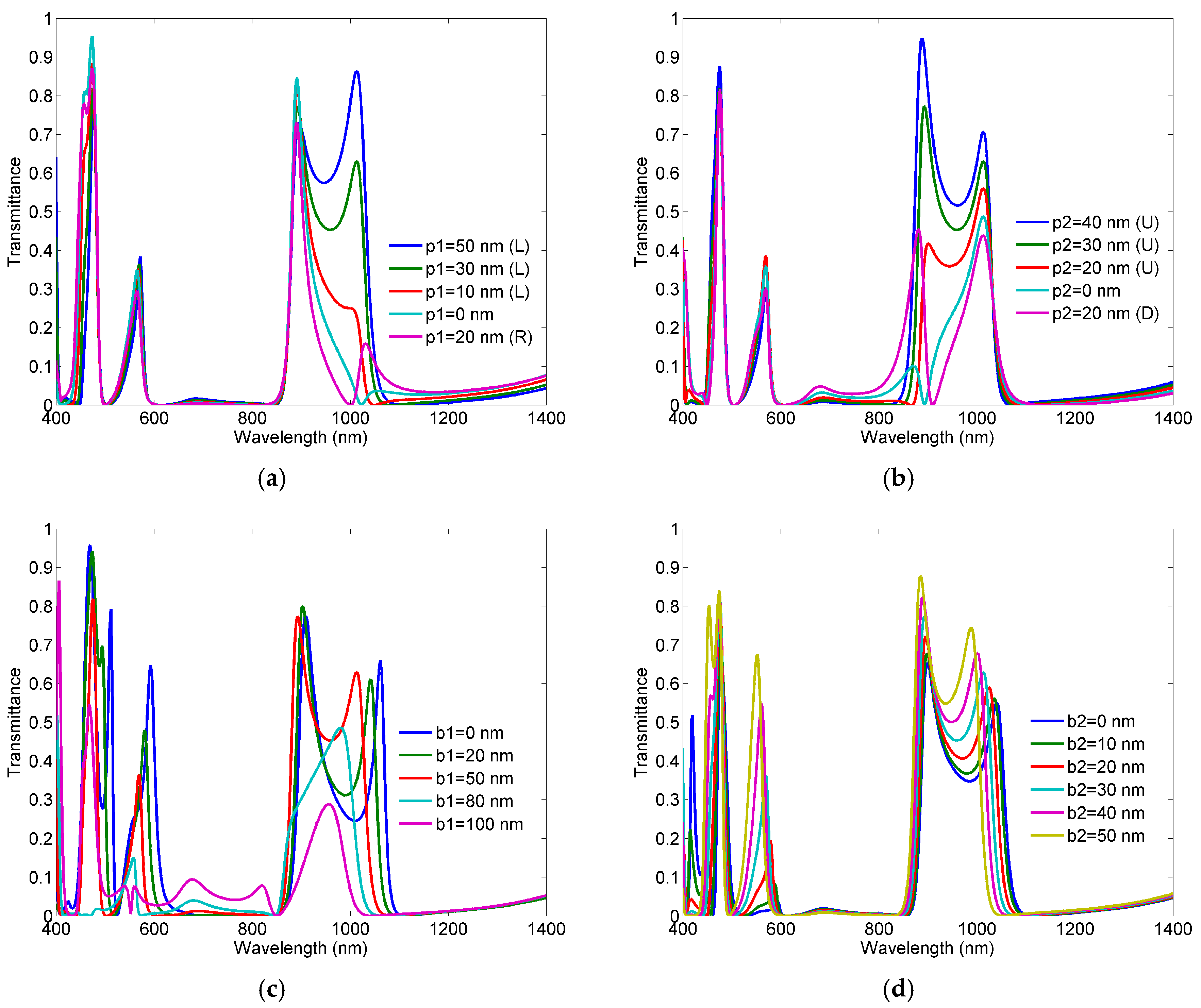
Figure 5 shows responses of the proposed structure for different values of the parameters p1, p2, b1, and b2. For each variation, all other parameters were kept constant.
The variation of the parameter p1 affects to the most extent the first resonant peak FR1, which is expected since, in the considered area of p1 variation, the first mode shows the most abrupt change of the magnetic field. Although one may argue that the structure with p1 = 50 nm exhibits better response in terms of transmittance magnitude, the solution with p1 = 30 nm provides steeper slope at the first two peaks FR1 and FR2, and suppresses the influence of the fifth mode to the fourth one (FR4). By the same token, the change of the parameter p2 influences primarily the second resonance FR2, since it shows the most abrupt change of the magnetic field in the area of the p2 variation.
When it comes to the parameter b1, its increase provides better slope in the third and fourth Fano-like resonances, FR3 and FR4, however it does so at the expense of the transmission magnitude at the two resonances. Therefore, the value of 50 nm has been chosen as a good trade-off between the steepness of peak-to-dip slope and the transmittance level. Similarly, the variation of the parameter b2 provides steeper peak-to-dip slope in the third and fourth resonances. However, it does so at the expense of the transmittance level and interference of the fourth and fifth modes. Thus, the value of 30 nm represents a good trade-off between these opposite requirements. We note here that both lower corners have been cut and finely tuned since combination of both disturbances has given better results than in the case of only one disturbance.
The previous analysis confirms that multiple Fano-like response with four narrow asymmetric profiles has been obtained primarily through the asymmetric feeding scheme. However, to obtain similar effect for all four modes, additional disturbances had to be introduced in the structure.
3. Sensing Potential of the Structure
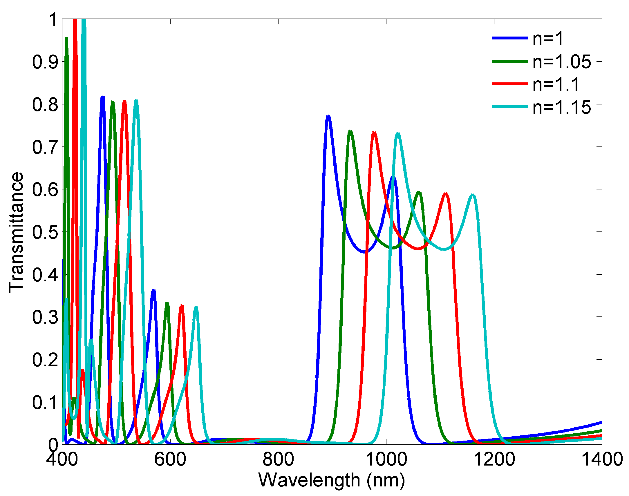
Sensing potential of the proposed structure is demonstrated through its response for different refractive indices of the dielectric marked in white in Figure 1. The geometrical parameters of the structure are those given in the previous section. The refractive index has been varied from 1 to 1.15 with the step of 0.05 and the corresponding responses are shown in Figure 6. It can be seen that the Fano-like response is preserved at all four resonances for each response.
The sensitivity of a sensor (nm/RIU) is usually defined as the shift in the resonance wavelength per unit variations of the refractive index [28]. According to the responses, the sensitivities are 986 nm/RIU, 866 nm/RIU, 520 nm/RIU, and 413 nm/RIU at FR1, FR2, FR3, and FR4, respectively. One should not be misled by the relatively low absolute values of the sensitivities at FR3 and FR4, since those sensitivities are related to the wavelength range 400–600 nm, and they actually represent high values relative to the wavelength range. In other words, each resonance is almost equally responsive to the change in the refractive index, if the above-mentioned sensitivities are perceived relatively to the wavelengths of the corresponding resonances.
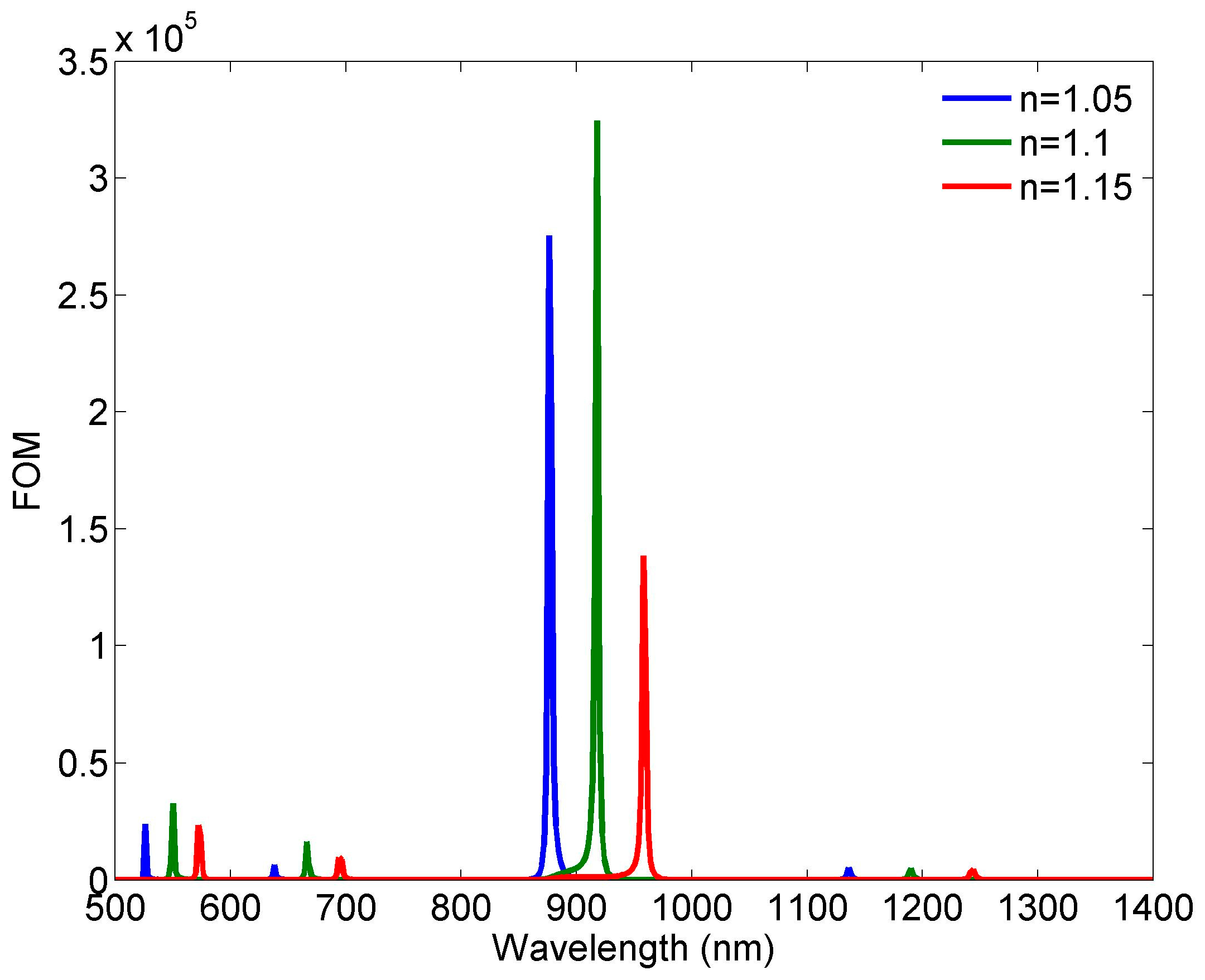
Another important and more illustrative parameter of a sensor performance is figure of merit (FOM), which is defined as FOM = ΔT/TΔn [28]. T denotes the transmittance in the proposed structure and ΔT/Δn denotes the transmission change at the fixed wavelength induced by a refractive index change. Figure 7 shows FOMs calculated for the refractive indices 1.05, 1.1, and 1.15 as FOM = (Tn = 1.05/1.1/1.15 − Tn = 1)/(Tn = 1Δn). Although the three FOM curves differ in the maximal values, it can be considered that FOM can reach the values of the order of 105 in the case of FR2, which is significantly greater than the most other proposed sensors. At the same time, the FOMs related to FR1, FR3, and FR4 have the values of 5366/5003/4549, 6465/16410/9762, and 24020/32870/23410, for n = 1.05/1.1/1.15, respectively. In addition, the transmittance levels at all four resonances are sufficiently high, which is not readily achievable.
The proposed sensor is compared to other similar structures in Table 1, where type denotes the number of Fano resonances exhibited by a structure. The proposed sensor has comparable sensitivity, however it considerably outperforms other solutions in terms of the maximal value of FOM and the number of Fano resonances. Namely, whilst most published sensors provide single, dual, or triple Fano resonances, the sensor in this work provides four Fano-like resonances using only one resonator, which allows both for miniaturization and multiple sensing check-points. In comparison to the quad-Fano sensor in [28], the proposed sensor has significantly higher FOMs at all four resonances, whilst the one in [30] has a maximal value one order lower than the proposed sensor. Therefore, the proposed sensor clearly demonstrates high sensing potential.
4. Conclusions
In this paper, we proposed a MIM structure based on isosceles triangular resonator for refractive index sensing applications. Due to the specific feeding scheme and asymmetry introduced in the triangular cavity, the sensor exhibits four sharp Fano-like resonances, which allows for excellent sensing performance. A detailed analysis of the sensor has shown that it has very good sensitivity and its maximal value of FOM reaches 3.2 × 10⁵. In comparison to other similar sensors, the proposed one has comparable sensitivity and significantly higher FOM, which clearly demonstrates its high sensing potential.
Acknowledgments
This work has been supported by FP7 project FRACTALS GA No. 632874.
Author Contributions
N.J. conceived the idea, supervised the research, and prepared the manuscript drafts. N.C. performed simulations and optimization, carried out the data analysis, and contributed to the manuscript drafts.
Conflicts of Interest
The authors declare no conflict of interest.
References
- Maier, S.A. Plasmonics: Fundamentals and Applications; Springer: New York, NY, USA, 2007; ISBN 978-0387331508. [Google Scholar]
- Barnes, W.L.; Dereux, A.; Ebbesen, T.W. Surface plasmon subwavelength optics. Nature 2013, 424, 824–830. [Google Scholar] [CrossRef] [PubMed]
- Zayats, A.V.; Smolyaninov, I.I.; Maradudin, A.A. Nano-optics of surface plasmon polaritons. Phys. Rep. 2005, 408, 131–314. [Google Scholar] [CrossRef]
- Luo, X.; Yan, L. Surface Plasmon Polaritons and Its Applications. IEEE Photonics J. 2012, 4, 590–595. [Google Scholar] [CrossRef]
- Zhang, J.; Zhang, L.; Xu, W. Surface plasmon polaritons: Physics and applications. J. Phys. D Appl. Phys. 2012, 45, 113001. [Google Scholar] [CrossRef]
- Fang, Y.; Sun, M. Nanoplasmonic waveguides: Towards applications in integrated nanophotonic circuits. Light Sci. Appl. 2015, 4, 294. [Google Scholar] [CrossRef]
- Lu, H.; Liu, X.; Wang, L.; Gong, Y.; Mao, D. Ultrafast all-optical switching in nanoplasmonic waveguide with Kerr nonlinear resonator. Opt. Express 2011, 19, 2910–2915. [Google Scholar] [CrossRef] [PubMed]
- Lu, H.; Liu, X.; Mao, D.; Wang, L.; Gong, Y. Tunable band-pass plasmonic waveguide filters with nanodisk resonators. Opt. Express 2010, 18, 17922–17927. [Google Scholar] [CrossRef] [PubMed]
- Zhang, Z.; Wang, J.; Zhao, Y.; Lu, D.; Xiong, Z. Numerical Investigation of a Branch-Shaped Filter Based on Metal-Insulator-Metal Waveguide. Plasmonics 2011, 6, 773–778. [Google Scholar] [CrossRef]
- Zhan, G.; Liang, R.; Liang, H.; Luo, J.; Zhao, R. Asymmetric band-pass plasmonic nanodisk filter with mode inhibition and spectrally splitting capabilities. Opt. Express 2014, 22, 9912–9919. [Google Scholar] [CrossRef] [PubMed]
- Wu, T.; Liu, Y.; Yu, Z.; Peng, Y.; Shu, C.; Ye, H. The sensing characteristics of plasmonic waveguide with a ring resonator. Opt. Express 2014, 22, 7669–7677. [Google Scholar] [CrossRef] [PubMed]
- Chen, L.; Liu, Y.; Yu, Z.; Wu, D.; Ma, R.; Zhang, Y.; Ye, H. Numerical analysis of a near-infrared plasmonic refractive index sensor with high figure of merit based on a fillet cavity. Opt. Express 2016, 24, 9975–9983. [Google Scholar] [CrossRef] [PubMed]
- Chen, Z.; Wang, W.; Cui, L.; Yu, L.; Duan, G.; Zhao, Y.; Xiao, J. Spectral splitting based on electromagnetically induced transparency in plasmonic waveguide resonator system. Plasmonics 2014, 10, 721–727. [Google Scholar] [CrossRef]
- Rahimzadegan, A.; Granpayeh, N.; Hosseini, S.P. Improved Plasmonic Filter, Ultra-Compact Demultiplexer, and Splitter. J. Opt. Soc. Korea 2014, 18, 261–273. [Google Scholar] [CrossRef]
- Fano, U. Effects of configuration interaction on intensities and phase shifts. Phys. Rev. 1961, 124, 1866–1878. [Google Scholar] [CrossRef]
- Luk’yanchuk, B.; Zheludev, N.I.; Maier, S.A.; Halas, N. J.; Nordlander, P.; Giessen, H.; Chong, T.C. The Fano resonance in plasmonic nanostructures and metamaterials. Nat. Mater. 2010, 9, 707–715. [Google Scholar] [CrossRef] [PubMed]
- Limonov, M.F.; Rybin, M.V.; Poddubny, A.N.; Kivshar, Y.S. Fano resonances in photonics. Nat. Photonics 2017, 11, 543–554. [Google Scholar] [CrossRef]
- Lovera, A.; Gallinet, B.; Nordlander, P.; Martin, O.J.F. Mechanisms of Fano Resonances in Coupled Plasmonic Systems. ACS Nano 2013, 7, 4527–4536. [Google Scholar] [CrossRef] [PubMed]
- Zafar, R.; Salim, M. Enhanced Figure of Merit in Fano resonance based Plasmonic Refractive Index Sensor. IEEE Sens. J. 2015, 15, 6313–6317. [Google Scholar] [CrossRef]
- Wen, K.; Hu, Y.; Chen, L.; Zhou, J.; Lei, L.; Meng, Z. Single/dual Fano resonance based on plasmonic metal-dielectric-metal waveguide. Plasmonics 2016, 11, 315–321. [Google Scholar] [CrossRef]
- Chen, Z.; Yu, L.; Wang, L.; Duan, G.; Zhao, Y.; Xiao, J. A Refractive Index Nanosensor Based on Fano Resonance in the Plasmonic Waveguide System. IEEE Photonics Technol. Lett. 2015, 27, 1695–1698. [Google Scholar] [CrossRef]
- Yun, B.; Zhang, R.; Hu, G.; Cui, Y. Ultra Sharp Fano Resonances Induced by Coupling between Plasmonic Stub and Circular Cavity Resonators. Plasmonics 2016, 11, 1157–1162. [Google Scholar]
- Yang, J.; Song, X.; Chen, Z.; Cui, L.; Yang, S.; Yu, L. Tunable Multi-Fano Resonances in MDM-Based Side-Coupled Resonator System and its Application in Nanosensor. Plasmonics 2017, 12, 1665–1672. [Google Scholar] [CrossRef]
- Wen, K.; Hu, Y.; Chen, L.; Zhou, J.; He, M.; Lei, L.; Meng, Z.; Wu, Y.; Li, J. Fano Resonance Based on End-Coupled Cascaded-Ring MIM Waveguides Structure. Plasmonics 2017, 12, 1875–1880. [Google Scholar] [CrossRef]
- Wang, Y.; Li, S.; Zhang, Y.; Yu, L. Ultrasharp Fano Resonances Based on the Circular Cavity Optimized by a Metallic Nanodisk. IEEE Photonics J. 2016, 8, 1–8. [Google Scholar] [CrossRef]
- Wang, Y.; Li, S.; Zhang, Y.; Yu, L. Independently Formed Multiple Fano Resonances for Ultra-High Sensitivity Plasmonic Nanosensor. Plasmonics 2016, 11, 1–7. [Google Scholar] [CrossRef]
- Tang, Y.; Zhang, Z.; Wang, R.; Hai, Z.; Xue, C.; Zhang, W.; Yan, S. Refractive Index Sensor Based on Fano Resonances in Metal-Insulator-Metal Waveguides Coupled with Resonators. Sensors 2017, 17, 784. [Google Scholar] [CrossRef] [PubMed]
- Zhao, T.; Yu, S. Ultra-High Sensitivity Nanosensor Based on Multiple Fano Resonance in the MIM Coupled Plasmonic Resonator. Plasmonics 2017, 12, 1–6. [Google Scholar] [CrossRef]
- Shang, X.-J.; Li, X.-F.; Wang, L.-L.; Zhai, X.; Lin, Q.; Wang, B.-X.; Liu, G.-D.; Xia, S.-X.; Li, Q. Realizing Fano-like resonance in a one terminal closed T-shaped waveguide. Eur. Phys. J. B 2015, 88, 144. [Google Scholar] [CrossRef]
- Zhang, Y.; Li, S.; Chen, Z.; Jiang, P.; Jiao, R.; Zhang, Y.; Wang, L.; Yu, L. Ultra-high Sensitivity Plasmonic Nanosensor Based on Multiple Fano Resonance in the MDM Side-Coupled Cavities. Plasmonics 2017, 12, 1099–1105. [Google Scholar] [CrossRef]
- Zhao, X.; Zhang, Z.; Yan, S. Tunable Fano Resonance in Asymmetric MIM Waveguide Structure. Sensors 2017, 17, 1494. [Google Scholar] [CrossRef] [PubMed]
- Zhang, Z.; Luo, L.; Xue, C.; Zhang, W.; Yan, S. Fano Resonance Based on Metal-Insulator-Metal Waveguide-Coupled Double Rectangular Cavities for Plasmonic Nanosensors. Sensors 2016, 16, 642. [Google Scholar] [CrossRef] [PubMed]
- Li, H.-J.; Wang, L-L.; Zhai, X. Fano response induced by the interference between localized plasmons and interface reflections in metal-insulator-metal waveguide structure. J. Appl. Phys. 2016, 119, 243101. [Google Scholar] [CrossRef]
- Chen, Z.; Yu, L. Multiple Fano Resonances Based on Different Waveguide Modes in a Symmetry Breaking Plasmonic System. IEEE Photonics J. 2014, 6, 1–8. [Google Scholar] [CrossRef]
- Zhou, J.; Chen, H.; Zhang, Z.; Tang, J.; Cui, J.; Xue, C.; Yan, S. Transmission and refractive index sensing based on Fano resonance in MIM waveguide-coupled trapezoid cavity. AIP Adv. 2017, 7, 015020. [Google Scholar] [CrossRef]
- Li, S.; Zhang, Y.; Song, X.; Wang, Y.; Yu, L. Tunable triple Fano resonances based on multimode interference in coupled plasmonic resonator system. Opt. Express 2016, 24, 15351–15361. [Google Scholar] [CrossRef] [PubMed]
- Li, S.; Wang, Y.; Jiao, R.; Wang, L.; Duan, G.; Yu, L. Fano resonances based on multimode and degenerate mode interference in plasmonic resonator system. Opt. Express 2017, 25, 3525–3533. [Google Scholar] [CrossRef] [PubMed]
- Wang, H.; Yang, J.; Zhang, J.; Huang, J.; Wu, W.; Chen, D.; Xiao, G. Tunable band-stop plasmonic waveguide filter with symmetrical multiple-teeth-shaped structure. Opt. Lett. 2016, 41, 1233–1236. [Google Scholar] [CrossRef] [PubMed]
- Campos, A.; Arbouet, A.; Martin, J.; Gérard, D.; Proust, J.; Plain, J.; Kociak, M. Plasmonic Breathing and Edge Modes in Aluminum Nanotriangles. ACS Photonics 2017, 4, 1257–1263. [Google Scholar] [CrossRef]
- Wysin, G.M. Electromagnetic modes in dielectric equilateral triangle resonators. J. Opt. Soc. Am. B 2006, 23, 1586–1599. [Google Scholar] [CrossRef]
- Xiao, J.-K.; Zu, X.-P.; Li, X.; Tian, L. Right-Angled Triangular Patch Resonator and Filter with Fractal Hole. Prog. Electromagn. Res. B 2012, 40, 141–158. [Google Scholar] [CrossRef]
Figure 1.
Layout of the proposed Fano MIM sensor with the corresponding geometrical parameters. Two MIM waveguides and triangular resonator are filled with air (marked in white) and surrounded with silver (marked in blue).
Figure 1.
Layout of the proposed Fano MIM sensor with the corresponding geometrical parameters. Two MIM waveguides and triangular resonator are filled with air (marked in white) and surrounded with silver (marked in blue).
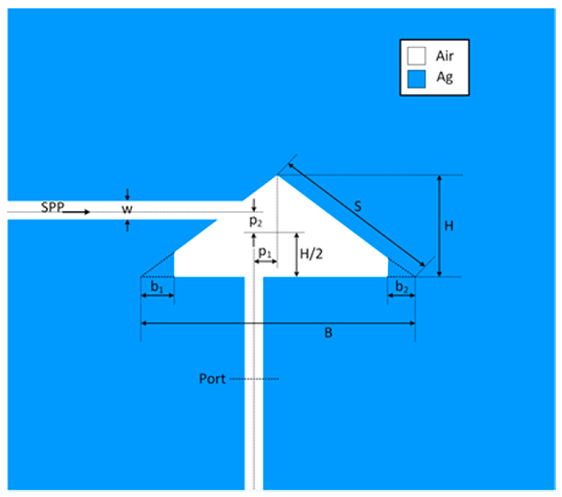
Figure 2.
Transmission spectrum of the proposed Fano MIM sensor.

Figure 3.
Spectral mode distribution for different types of triangular cavity resonators.

Figure 4.
Normalized Hz field distribution at eigenmode resonant frequencies for isosceles triangular resonator.
Figure 4.
Normalized Hz field distribution at eigenmode resonant frequencies for isosceles triangular resonator.

Figure 5.
Response of the proposed sensor for different values of the parameter: (a) p1, L/R denotes left/right position from the symmetry axis; (b) p2 U/D denotes upper/down position from the half-height point; (c) b1; (d) b2.
Figure 5.
Response of the proposed sensor for different values of the parameter: (a) p1, L/R denotes left/right position from the symmetry axis; (b) p2 U/D denotes upper/down position from the half-height point; (c) b1; (d) b2.

Figure 6.
Responses of the sensor for different refractive indices.

Figure 7.
Calculated FOM for different refractive indices.

Table 1.
Comparison of the proposed sensor and other recently published similar solutions.
| Reference | Type | Sensitivity [nm/RIU] | FOM |
|---|---|---|---|
| [20] | dual | 888/1187 | 22,000/29,000 |
| [21] | single | 1260 | 23,000 |
| [22] | single | 1277 | 22,000 |
| [23] | dual | 850/1120 | 74000/170,000 |
| [24] | dual | 900/1050 | 14,400/16,500 |
| [25] | dual | 1450/800 | 35,100/33,500 |
| [26] | triple | 1700/2000/1000 | 7100/8600/7500 |
| [28] | quad | 200/600/600/2000 | 3000/500/1500/200 |
| [29] | single | 1114 | 7961 |
| [30] | quad | 700/800/1900/1600 | Max 38,000 |
| [31] | single | 718 | 4354 |
| [34] | dual | 820/1100 | 7000/320,000 |
| [36] | triple | 600/500/500 | 3803/816/2947 |
| [37] | triple | 850/750/950 | 100/100/100 |
| This work | quad | 416/520/866/986 | 32,870/16,410/324,600/5003 |
© 2018 by the authors. Licensee MDPI, Basel, Switzerland. This article is an open access article distributed under the terms and conditions of the Creative Commons Attribution (CC BY) license (http://creativecommons.org/licenses/by/4.0/).
Share and Cite
MDPI and ACS Style
Jankovic, N.; Cselyuszka, N. Multiple Fano-Like MIM Plasmonic Structure Based on Triangular Resonator for Refractive Index Sensing. Sensors 2018, 18, 287. https://doi.org/10.3390/s18010287
AMA Style
Jankovic N, Cselyuszka N. Multiple Fano-Like MIM Plasmonic Structure Based on Triangular Resonator for Refractive Index Sensing. Sensors. 2018; 18(1):287. https://doi.org/10.3390/s18010287
Chicago/Turabian StyleJankovic, Nikolina, and Norbert Cselyuszka. 2018. "Multiple Fano-Like MIM Plasmonic Structure Based on Triangular Resonator for Refractive Index Sensing" Sensors 18, no. 1: 287. https://doi.org/10.3390/s18010287
Note that from the first issue of 2016, this journal uses article numbers instead of page numbers. See further details here.