Dual-Band Band-Pass Filter with Fixed Low Band and Fluidically-Tunable High Band


School of Electrical and Electronics Engineering, College of Engineering, Chung-Ang University, 84 Heukseok-ro, Dongjak-gu, Seoul 06974, Korea
*
Author to whom correspondence should be addressed.
Sensors 2017, 17(8), 1884; https://doi.org/10.3390/s17081884
Submission received: 4 July 2017
/
Revised: 14 August 2017
/
Accepted: 14 August 2017
/
Published: 16 August 2017
(This article belongs to the Special Issue Microfluidic Sensors)
Abstract
:In this work, we present a dual-band band-pass filter with fixed low-band resonant frequency and tunable high-band resonant frequency. The proposed filter consists of two split-ring resonators (SRRs) with a stub and microfluidic channels. The lower resonant frequency is determined by the length of the SRR alone, whereas the higher resonant frequency is determined by the lengths of the SRR and the stub. Using this characteristic, we fix the lower resonant frequency by fixing the SRR length and tune the higher resonant frequency by controlling the stub length by injecting liquid metal in the microfluidic channel. We fabricated the filter on a Duroid substrate. The microfluidic channel was made from polydimethylsiloxane (PDMS), and eutectic gallium–indium (EGaIn) was used as the liquid metal. This filter operates in two states—with, and without, the liquid metal. In the state without the liquid metal, the filter has resonant frequencies at 1.85 GHz and 3.06 GHz, with fractional bandwidths of 4.34% and 2.94%, respectively; and in the state with the liquid metal, it has resonant frequencies at 1.86 GHz and 2.98 GHz, with fractional bandwidths of 4.3% and 2.95%, respectively.
1. Introduction
The increasing number of multi-standard and multi-application telecommunication systems including cognitive radios [1], modern transceivers [2], anti-jamming communication systems [3], and radar systems [4], has led to the development of new tunable filter topologies [5,6]. Such system require microwave circuits and components that can control variety different frequency bands and bandwidths. To meet the requirements in a variety of areas, such as the WLAN system, the design of multi-bandpass filters with tunable frequencies is essential due to their potential to reduce system size and complexity [7,8,9].
Tunable filters can be developed electronically, using solid-state varactors or switches, microelectromechanical system (MEMS) [10,11,12,13] switches or capacitors, or variable dielectric capacitors; magnetically, using yttrium–iron–garnet (YIG) [14,15]; or by using RF switches exploiting phase-changing materials [16]. Tunable filters that use new materials such as liquid crystals (LC) or liquid metals have recently been reported. The LC tunable filter is based on the property wherein the arrangement of the LC changes when a voltage is applied [17]. In the case of filters that use liquid metals, the filters utilize the properties of the liquid metal, which possesses properties of both liquids and solids and moved by pressure alone [18]. Using these characteristics, the performance of the device has been improved in various fields, such as antennas [19], sensors [20], amplifiers [21], baluns [22], and resonators [23]. Especially, single-band tunable filters using liquid metal as a tunable device have been developed in low-pass filters and band-pass filters [24,25]. In this work, we propose a dual band tunable bandpass filter using liquid metal. In addition, the proposed filter can change only the high-band resonant frequency while fixing the low-band resonant frequency. The fixed frequency is 1.8 GHz band which can be used for wireless communications [26]. On the other hands, the tunable band can be used for sensors to detect liquid materials.
In this work, the fundamental structure of the filter employed is a dual-band band-pass filter (BPF) structure using stub-loaded resonators [27,28]. We realized the fixed-low-band and reconfigurable-high-band filter by changing the stub length, using liquid metal and microfluidic channels. The liquid metal used was eutectic gallium–indium (EGaIn), consisting of 24.5% indium and 75.5% gallium [29]. EGaIn provides advantages over other liquid metals. It has a low level of toxicity and has a thin, solid-like oxide skin on its surface to improve mechanical stability [30]. The microfluidic channels used as the paths for the liquid metal were made of polydimethylsiloxane (PDMS) elastomer and 3D-printed frames [31]. The performance of the proposed BPF is validated from both simulation and measurements.
2. Frequency-Tunable Band-Pass Filter Design
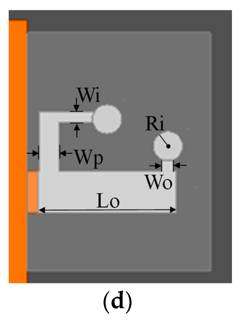
In this paper, we present a dual-band BPF with a fixed low-band resonant frequency and a fluidically-tunable high-band resonant frequency. The design of the proposed BPF is based on a coupled resonator filter that uses two split-ring resonators, as shown in Figure 1a. To realize the dual-band BPF, we add a stub to the coupled resonator filter, as shown in in Figure 1b. Finally, we add a microfluidic channel to the coupled-resonator filter with stub to create the frequency-controllable filter shown in Figure 1c. The detailed design of the microfluidic channel for frequency switching, which is created using polydimethylsiloxane (PDMS), is shown in Figure 1d. The values of the parameters in Figure 1 are La = 80, Lr = 17.3, Lf = 4.492, Lq = 17.823, Ls = 9, Lo = 1, Lc = 7.065, Wa = 30, Wr = 1.8, Wq = 0.83, Wf = 1.5, Ws = 2.1, Wp = 1, Wi = 0.55, Wo = 0.6, Gr = 0.77, Gc = 0.77, and R(SA (θ)) = 0.75 [mm].
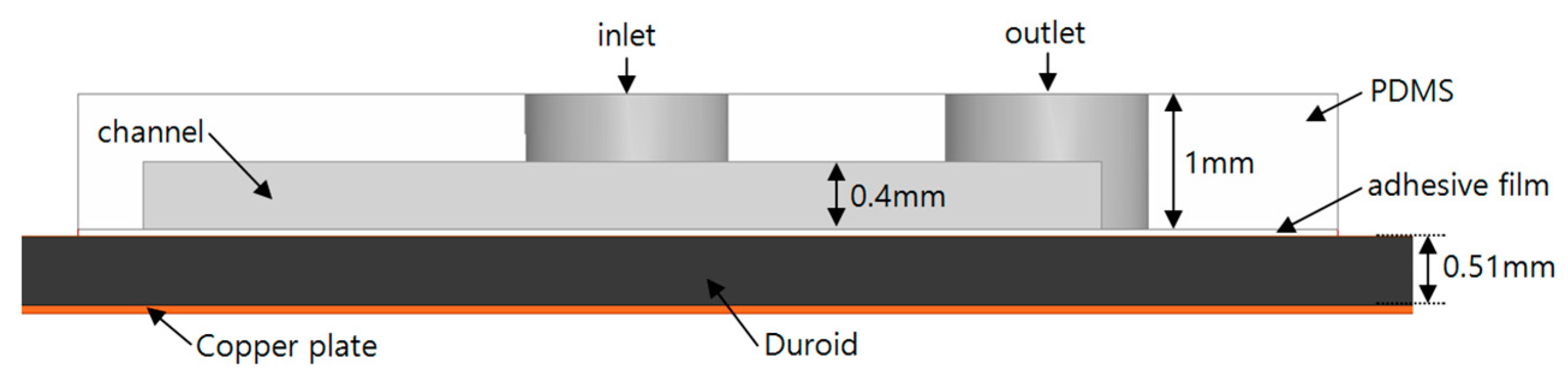
Figure 2 shows the side view of the proposed filter. The proposed filter consists of a copper plate, Duroid substrate, adhesive film, and PDMS. The bottom layer is the copper plate, which acts as the ground. The substrate for the proposed filter is a 0.51 mm thick Duroid 5880 substrate (Rogers, Killingly, CT, USA), with a permittivity of 2.2. The adhesive film bonds the Duroid substrate and the PDMS layer. We used 0.05 mm thick ARcare® 92561 (Adhesives Research, Glen Rock, PA, USA) for the adhesive film which can be simply attached on the PCB substrate without any post processing. PDMS, with a permittivity of 3.2, is used to create the microfluidic channel. The resonant frequency of the proposed filter is divided into two types of modes. The lower one is the odd mode and the other is the even mode. The odd-mode frequency (fodd) is related to the length of the split-ring resonator, which is Lr in Figure 1a. The relationship between the odd-mode frequency (fodd) and Lr is given by:
where c is the velocity of light and n is a positive integer and εeff is the effective permittivity of the substrate.
The even-mode frequency is related to the length of the split-ring resonator and the length of the stub; that is, the sum of Ls and Lo in Figure 1b. The relationship between the even-mode frequency (feven) and Lr, Ls, and Lo is given by:
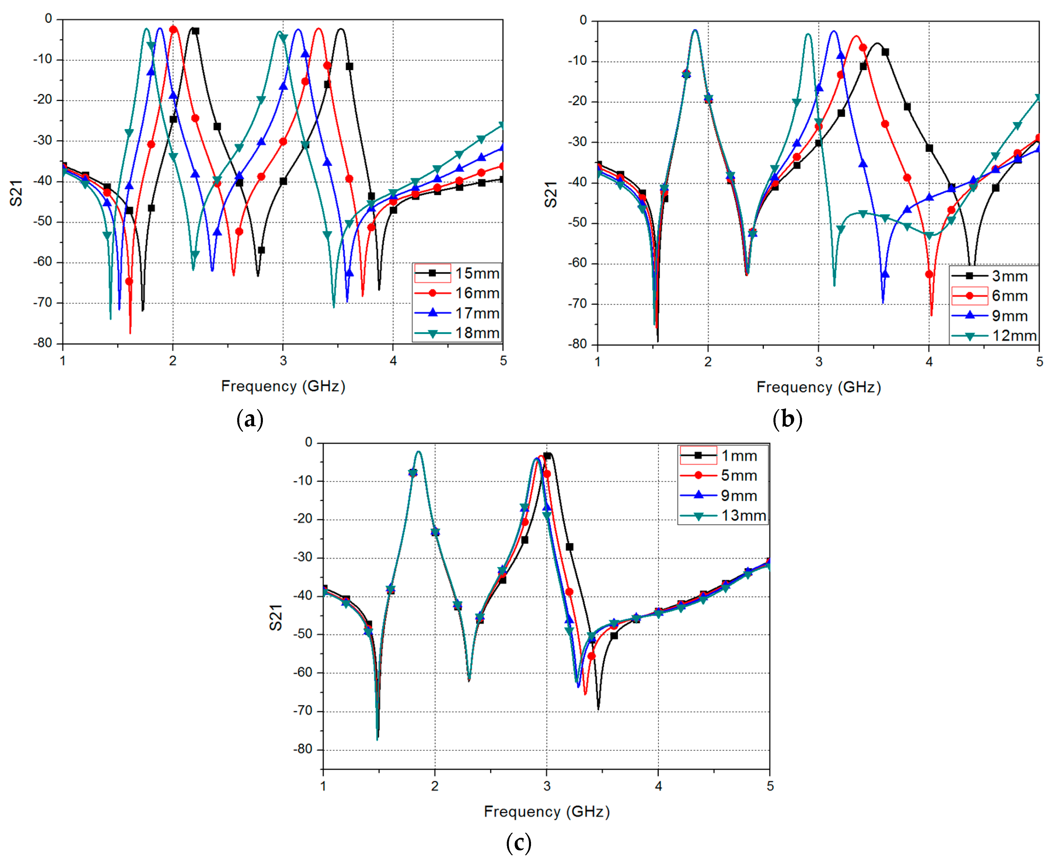
Figure 3 shows the simulation results of the proposed filter for different parameters. Figure 3a shows the insertion loss (S21) of the proposed filter, for different Lr. When Lr is increased, the odd frequency and even frequency are decreased according to Equations (1) and (2), respectively. Figure 3b shows the S21 of the proposed filter, for different Ls. When Ls is increased, the even-mode frequency is decreased, but the odd-mode frequency is not changed, according to Equations (1) and (2). Using this characteristic, the proposed filter can fix the odd frequency and change the even frequency by controlling the length of the stub. To control the length of the stub, we add a microfluidic channel to the stub of the filter. Due to the limited space inside the SRR, we loaded the microfluidic channel to change Lo instead of Ls. Therefore, we can minimize electromagnetic coupling. When liquid metal is injected into the microfluidic channel, the length of the stub is increased depending on the length of the microfluidic channel, which is given by Lc in Figure 1d. Figure 3c shows the S21 of the proposed filter, for different Lc, when liquid metal is injected into the microfluidic channel. When Lc is increased, the odd frequency shows no change, but the even frequency is decreased.
The S-parameters of the proposed filter are shown in Figure 4, for the different cases where liquid metal is injected and not injected into the microfluidic channel. The odd-mode frequency of the proposed filter without liquid metal is 1.85 GHz, and the fractional bandwidth is 4.32%. The even-mode frequency of the proposed filter without liquid metal is 3.05 GHz, and the fractional bandwidth is 2.96%. The odd-mode frequency of the proposed filter with liquid metal is 1.85 GHz, and the fractional bandwidth is 4.32%. The even-mode frequency of the proposed filter with liquid metal is 2.9 GHz, and the fractional bandwidth is 2.75%. From these results, it can be inferred that, when liquid metal is injected into the microfluidic channel, the odd-mode frequency is not changed, while the even-mode frequency is shifted by approximately 150 MHz.
The fractional bandwidth is defined by the following equation [32]:
where ffh and ffl are higher and lower 3 dB frequency and fc is center frequency.
3. Fabrication and Measurement
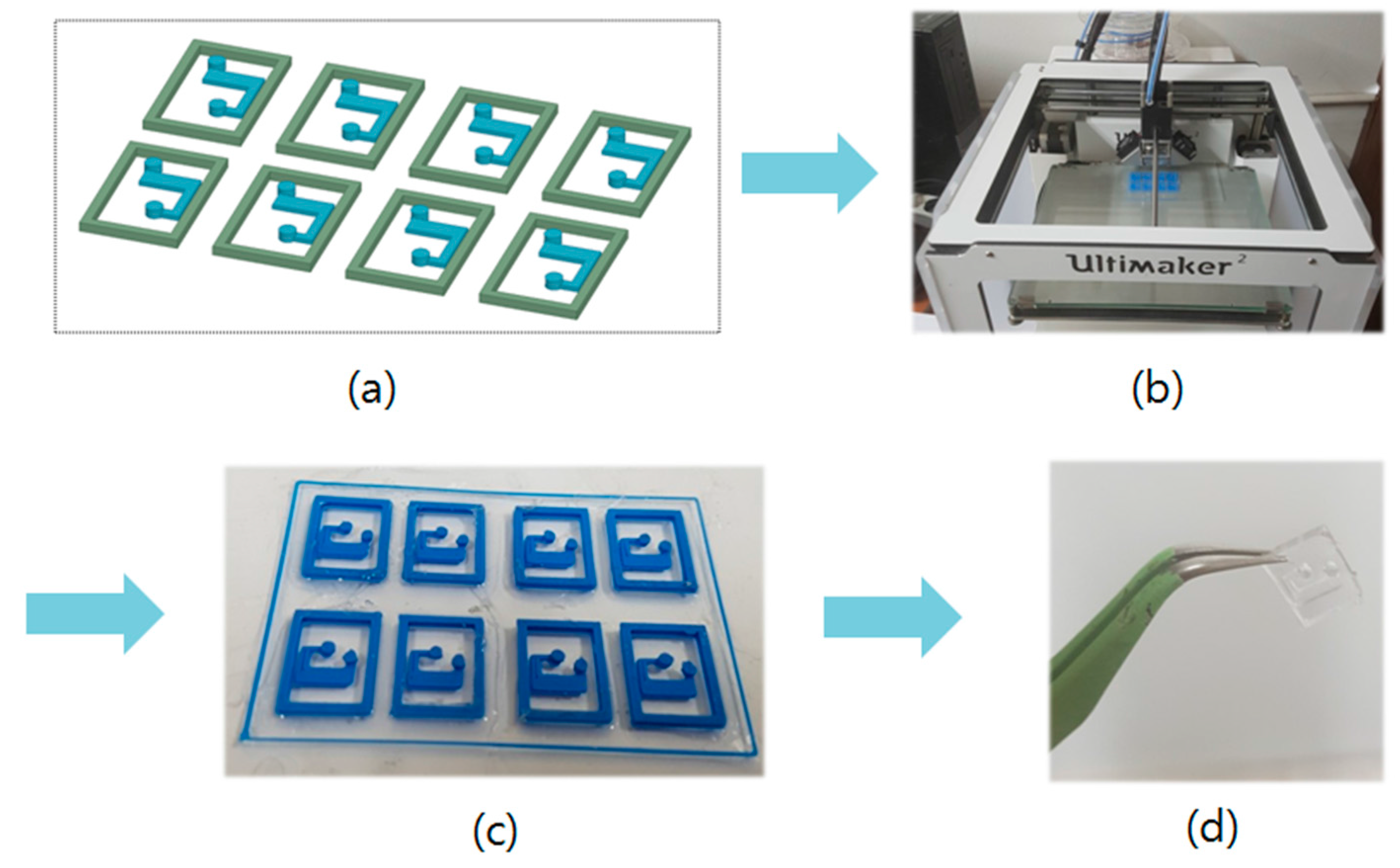
Figure 5 shows the fabrication of the PDMS microfluidic channel. First, we make a mold for the PDMS microfluidic channel, before fabricating it, because we cannot fabricate the PDMS channel using a 3D printer alone. To make the mold for the channel, we design a mold using a 3D modeler program, as shown in Figure 5a. The designed mold is realized using a 3D printer (Ultimaker2, Geldermalsen, The Netherlands), as shown in in Figure 5b. Then, we fabricate the PDMS channel using the mold. Figure 5c shows the fabricated mold. We create PDMS by solidifying the liquid made by mixing Sylgard184 Base and Sylgard184 Agent in the ratio of 10:1. We then fabricate the PDMS channel by pouring the mixed liquid into the mold and solidifying by heating for 30 min. Figure 5d shows the fabricated microfluidic channel.
Figure 6a,b shows pictures of samples of the fabricated proposed filter. The substrate is realized using Duroid 5880 board (Rogers, Killingly, CT, USA). The patterns on the top and ground of the sample are realized using copper. Microfluidic channels made by the process in Figure 5 are attached onto the pattern and substrate. The difference between Figure 6a,b is the liquid metal is not injected in the microfluidic channel in Figure 6a and injected in the microfluidic channel in Figure 6b. We use eutectic gallium–indium (EGaIn) for the liquid metal. For injecting EGaIn into the microfluidic channel and extracting EGaIn from the microfluidic channel, we use an injector named Pipetman, shown in Figure 6c.
Table 1 shows comparisons of the measured and simulated result of the proposed filter. The S-parameters of the filter are measured using an Anritsu MS2038C. When the proposed filter without EGaIn, the odd-mode frequency of the proposed filter is 1.85 GHz, and is the same in both the results. The even-mode frequency of the measured result is 3.06 GHz, and the even-mode frequency of the simulation result is 3.05 GHz, which show a very small difference. When the proposed filter with EGaIn, the odd-mode frequency of the measured result is 1.85 GHz, and the odd-mode frequency of the simulation result is 1.86 GHz. The even-mode frequency of the measured result is 2.98 GHz, whereas the even-mode frequency of the simulation result is 2.9 GHz.
The measurement resonant frequency with EGaIn is slightly higher than the simulated resonant frequencies. As shown in Figure 3c, the insertion loss is increased with lower resonant frequency because of larger EGaIn. Therefore, the measured insertion loss with EGaIn is higher than the simulated insertion loss with EGaIn.
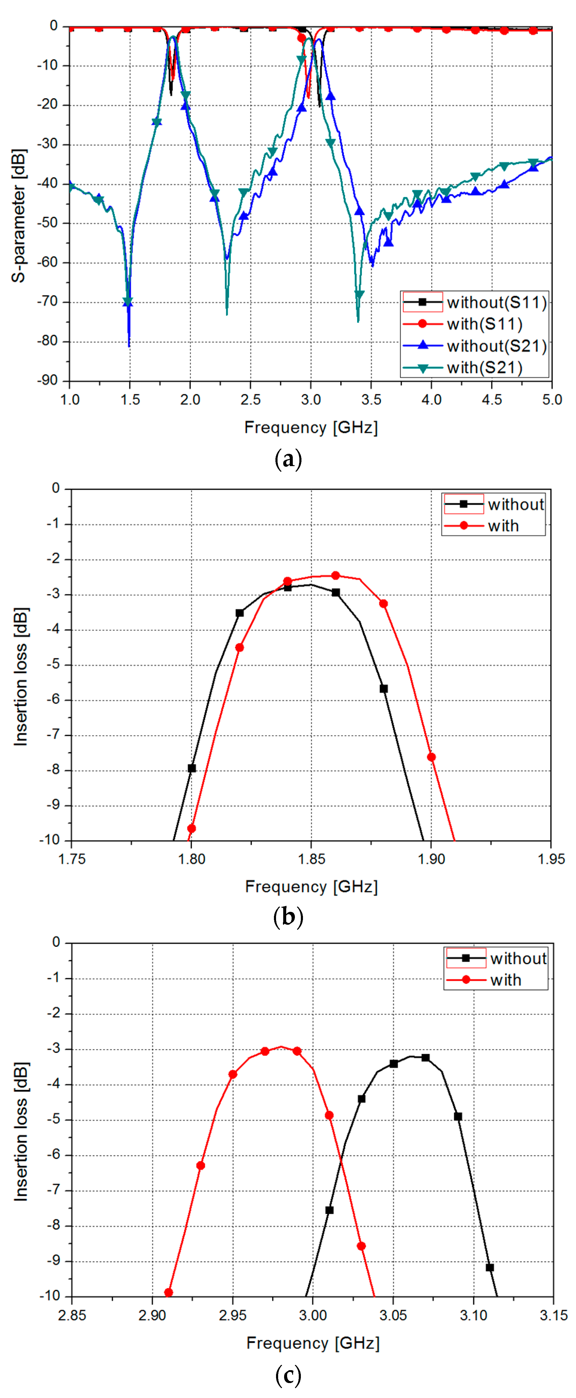
Figure 7 shows the measured results of the S-parameters of the proposed filter without and with EGaIn. For the odd mode, the filter without EGaIn has the insertion loss of 2.72 dB at 1.85 GHz and a fractional bandwidth of 4.34%. The filter with EGaIn has the insertion loss of 2.5 dB at 1.86 GHz and a fractional bandwidth of 4.3%.
In this graph, when EGaIn is injected into the microfluidic channel, the odd-mode frequency and fractional bandwidth are not changed. For the even mode, the filter without EGaIn has the insertion loss of 3.21 dB at 3.06 GHz and a fractional bandwidth of 2.94%. The filter with EGaIn has the insertion loss of 2.5 dB at 2.98 GHz and a fractional bandwidth of 2.95%.
In this graph, when EGaIn is injected into the microfluidic channel, the even-mode frequency is shifted by 0.11 GHz and the fractional bandwidth is slightly decreased.
4. Conclusions
In this paper, we proposed a dual-band BPF with fixed low-band resonant frequency and fluidically-tunable high-band frequency. The filter consisted of two split-ring resonators, a stub for providing dual-band operation, and a microfluidic channel for tuning the frequency. The proposed filter was based on the characteristic that the lower resonant frequency was determined by the length of the SRR and the higher resonant frequency by the lengths of the SRR and the stub. We controlled the length of the stub using a microfluidic channel and EGaIn, to fix the lower-band frequency and tune the higher-band frequency. The filter was fabricated on a Duroid 5880 substrate and the microfluidic channel was fabricated using a 3D Printer. From the measurement results, the lower band frequency was found to be fixed at 1.85 GHz and the higher band frequency was found to be shifted from 3.06 GHz to 2.95 GHz, when EGaIn was injected into the microfluidic channel.
In Table 2, we compared the performances of the proposed filters with those of other tunable filters using liquid metal. Although insertion losses is higher than other filters, the propose filter operates at dual band. In addition, only high band resonant frequency can be controlled while fixing the low band resonant frequency. The tuning range is defined by the following equation:
where flow and fhigh are lowest and highest resonant frequencies, respectively. The tuning range can be increased by increasing the length of the microfluidic channel and injecting more liquid metal in the microfluidic channel.
Acknowledgments
This work was supported by the National Research Foundation of Korea (NRF) grant funded by the Korea government (MSIP) (no. 2017R1A2B3003856) and the Chung-Ang University Graduate Research Scholarship in 2017.
Author Contributions
Eiyong Park designed, fabricated, and measured the samples. Daecheon Lim fabricated and measured the samples. Eiyong Park and Daecheon Lim wrote the manuscript and contributed equally as first authors. Sungjoon Lim conceived the idea and contributed to the revision of the manuscript.
Conflicts of Interest
The authors declare no conflicts of interest.
References
- Kim, D. A High Performance Ibc-Hub Transceiver for Intra-Body Communication System. Microw. Opt. Technol. Lett. 2012, 54, 2781–2784. [Google Scholar]
- Soury, A.; Ngoya, E.; Rousset, J. Behavioral Modeling of RF and Microwave Circuit Blocs for Hierarchical Simulation of Modern Transceivers. In Proceedings of the 2005 IEEE MTT-S International Microwave Symposium Digest, Long Beach, CA, USA, 17 June 2005; pp. 975–978. [Google Scholar]
- Christina, P. Anti-Jamming Broadcast Communication Using Uncoordinated Spread Spectrum Techniques. IEEE J. Sel. Areas Commun. 2010, 28. [Google Scholar] [CrossRef]
- Jordan, R.L.; Huneycutt, B.L.; Werner, M. The SIR-C/X-SAR Synthetic Aperture Radar System. IEEE Trans. Geosci. Remote Sens. 1995, 33, 829–839. [Google Scholar] [CrossRef]
- Behavior, D.; Introduction, I. Bandwidth and Central Frequency Control on Tunable Bandpass Filter by Using MEMS Cantilevers. In Proceedings of the 2003 IEEE MTT-S International Microwave Symposium Digest, Philadelphia, PA, USA, 8–13 June 2003; pp. 523–526. [Google Scholar]
- Shim, Y.; Member, S.; Wu, Z.; Member, S. A High-Performance Continuously Tunable MEMS Bandpass Filter at 1 GHz. IEEE Trans. Microw. Theory Tech. 2012, 60, 2439–2447. [Google Scholar] [CrossRef]
- Chaudhary, G.; Jeong, Y.; Lim, J. Dual-Band Bandpass Filter with Independently Tunable Center Frequencies and Bandwidths. IEEE Trans. Microw. Theory Tech. 2013, 61, 107–116. [Google Scholar] [CrossRef]
- Danideh, A.; Sadeghzadeh, R.A. CPW-Fed Slot Antenna for Mimo System Applications. Indian J. Sci. Technol. 2013, 6, 3872–3875. [Google Scholar] [CrossRef]
- Huang, X.; Feng, Q.; Xiang, Q. Bandpass Filter with Tunable Bandwidth Using Quadruple-Mode Stub-Loaded Resonator. IEEE Microw. Wirel. Compon. Lett. 2012, 22, 176–178. [Google Scholar] [CrossRef]
- Pillans, B.; Malczewski, A.; Allison, R.; Brank, J. 6–15 GHz RF MEMS Tunable Filters. In Proceedings of the 2005 IEEE MTT-S International Microwave Symposium Digest, Long Beach, CA, USA, 17 June 2005; pp. 919–922. [Google Scholar]
- Brank, J.; Yao, J.; Eberly, M.; Malczewski, A.; Varian, K.; Goldsmith, C. RF MEMS-Based Tunable Filters. Int. J. RF Microw. Comput.-Aided Eng. 2001, 11, 276–284. [Google Scholar] [CrossRef]
- Entesari, K.; Rebeiz, G.M. A differential 4-bit 6.5–10-GHz RF MEMS Tunable Filter. IEEE Trans. Microw. Theory Tech. 2005, 53, 1103–1110. [Google Scholar] [CrossRef]
- Entesari, K.; Rebeiz, G.M. A 12–18-GHz three-pole RF MEMS Tunable Filter. IEEE Trans. Microw. Theory Tech. 2005, 53, 2566–2571. [Google Scholar] [CrossRef]
- Tsai, C.S.; Qiu, G.; Gao, H.; Li, G.P.; Yang, L.W.; Nikitov, S.A.; Gulyaev, Y. Tunable Wideband Microwave Band-Stop and Band-Pass Filters Using YIG/GGG-GaAs Layer Structures. IEEE Trans. Magn. 2005, 41, 3568–3570. [Google Scholar] [CrossRef]
- Murakami, Y.; Ohgihara, T.; Okamoto, T. A 0.5–4.0-GHz Tunable Bandpass Filter Using YIG Film Grown by LPE. IEEE Trans. Microw. Theory Tech. 1987, 35, 1192–1198. [Google Scholar] [CrossRef]
- Sanphuang, V.; Ghalichechian, N.; Nahar, N.K.; Volakis, J.L. Bandwidth Reconfigurable THz Filter Employing Phase-Change Material. In Proceedings of the 2015 IEEE International Symposium on Antennas and Propagation & USNC/URSI National Radio Science Meeting, Vancouver, BC, Canada, 19–24 July 2015; pp. 2289–2290. [Google Scholar]
- Goelden, F.; Gaebler, A.; Karabey, O.; Goebel, M.; Manabe, A.; Jakoby, R. Tunable Band-Pass Filter Based on Liquid Crystal. In Proceedings of the German Microwave Conference, Berlin, Germany, 15–17 March 2010; Volume 8, pp. 98–101. [Google Scholar]
- Guo, S.; Lei, B.J.; Hu, W.; Shiroma, W.A.; Ohta, A.T. A Tunable Low-Pass Filter Using a Liquid-Metal Reconfigurable Periodic Defected Ground Structure. In Proceedings of the 2012 IEEE MTT-S International Microwave Symposium Digest (MTT), Montreal, QC, Canada, 17–22 June 2012; pp. 1–3. [Google Scholar] [CrossRef]
- Gough, R.C.; Dang, J.H.; Morishita, A.M.; Ohta, A.T.; Shiroma, W.A. Frequency-Tunable Slot Antenna Using Continuous Electrowetting of Liquid Metal. In Proceedings of the 2014 IEEE MTT-S International Microwave Symposium (IMS), Tampa, FL, USA, 1–6 June 2014; pp. 1–3. [Google Scholar] [CrossRef]
- Traille, A.; Bouaziz, S.; Pinon, S.; Pons, P.; Aubert, H.; Boukabache, A. A Wireless Passive RCS-Based Temperature Sensor using Liquid Metal and Microfluidics Technologies. In Proceedings of the 2011 41st European Microwave Conference (EuMC), Manchester, UK, 10–13 Octobor 2011; pp. 45–48. [Google Scholar]
- Morishita, A.M.; Dang, J.H.; Gough, R.C.; Ohta, A.T.; Shiroma, W.A. A Tunable Amplifier Using Reconfigurable Liquid-Metal Double-Stub Tuners. In Proceedings of the 2015 Texas Symposium on Wireless and Microwave Circuits and Systems (WMCS), Waco, TX, USA, 23–24 April 2015; pp. 4–7. [Google Scholar] [CrossRef]
- Morishita, A.M.; Gough, R.C.; Dang, J.H.; Ohta, A.T.; Shiroma, W.A. A Liquid-Metal Reconfigurable Log-Periodic Balun. In Proceedings of the 2014 IEEE MTT-S International Microwave Symposium (IMS), Tampa, FL, USA, 1–6 June 2014; pp. 8–10. [Google Scholar] [CrossRef]
- Khan, M.R.; Hayes, G.J.; Zhang, S.; Dickey, M.D.; Lazzi, G. A Pressure Responsive Fluidic Microstrip Open Stub Resonator Using a Liquid Metal Alloy. IEEE Microw. Wirel. Compon. Lett. 2012, 22, 577–579. [Google Scholar] [CrossRef]
- Mumcu, G.; Dey, A.; Palomo, T. Frequency-Agile Bandpass Filters Using Liquid Metal Tunable Broadside Coupled Split Ring Resonators. IEEE Microw. Wirel. Compon. Lett. 2013, 23, 187–189. [Google Scholar] [CrossRef]
- Eom, S.; Memon, M.U.; Lim, S. Frequency-Switchable Microfluidic CSRR-Loaded QMSIW Band-Pass Filter Using a Liquid Metal Alloy. Sensors 2017, 17, 699. [Google Scholar] [CrossRef] [PubMed]
- Sun, J.-S.; Fang, H.-S.; Lin, P.-Y.; Chuang, C.-S. Triple-band MIMO Antenna for Mobile Wireless Applications. IEEE Antennas Wirel. Propag. Lett. 2016, 15, 500–503. [Google Scholar] [CrossRef]
- Hong, J.S.; Lancaster, M.J. Canonical Microstrip Filter Using Square Open-Loop Resonators. Electron. Lett. 1995, 31, 2020–2022. [Google Scholar] [CrossRef]
- Resonators, S.; Zhang, X.Y.; Member, S.; Chen, J.; Member, S.; Xue, Q.; Member, S. Dual-Band Bandpass Filters Using. IEEE Microw. Wirel. Compon. Lett. 2007, 17, 583–585. [Google Scholar]
- Ling, K.; Kim, H.; Yoo, M.; Lim, S. Frequency-Switchable Metamaterial Absorber Injecting Eutectic Gallium-Indium (EGaIn) Liquid Metal Alloy. Sensors 2015, 15, 28154–28165. [Google Scholar] [CrossRef] [PubMed]
- Dickey, M.D.; Chiechi, R.C.; Larsen, R.J.; Weiss, E.A.; Weitz, D.A.; Whitesides, G.M. Eutectic Gallium–Indium (Egain): A Liquid Metal Alloy for the Formation of Stable Structures in Microchannels at Room Temperature. Adv. Funct. Mater. 2008, 18, 1097–1104. [Google Scholar] [CrossRef]
- Lee, J.; Bang, J.; Choi, J. Realistic Head Phantom for Evaluation of Brain Stroke Localization Methods Using 3D Printer. J. Electromagn. Eng. Sci. 2016, 16, 254–258. [Google Scholar] [CrossRef]
- Kwon, K.-A.; Kim, H.-K.; Yun, S.-W. Design of Dual-Band Bandpass Filters for Congnitivie Radio Application of TVWS Band. J. Electromagn. Eng. Sci. 2016, 16, 19–23. [Google Scholar] [CrossRef]
Figure 1.
Top view of the proposed filter: (a) using two split-ring resonators (SRR); (b) with stub; (c) with stub and microfluidic channel; and (d) an enlarged top view of the microfluidic channel.
Figure 1.
Top view of the proposed filter: (a) using two split-ring resonators (SRR); (b) with stub; (c) with stub and microfluidic channel; and (d) an enlarged top view of the microfluidic channel.
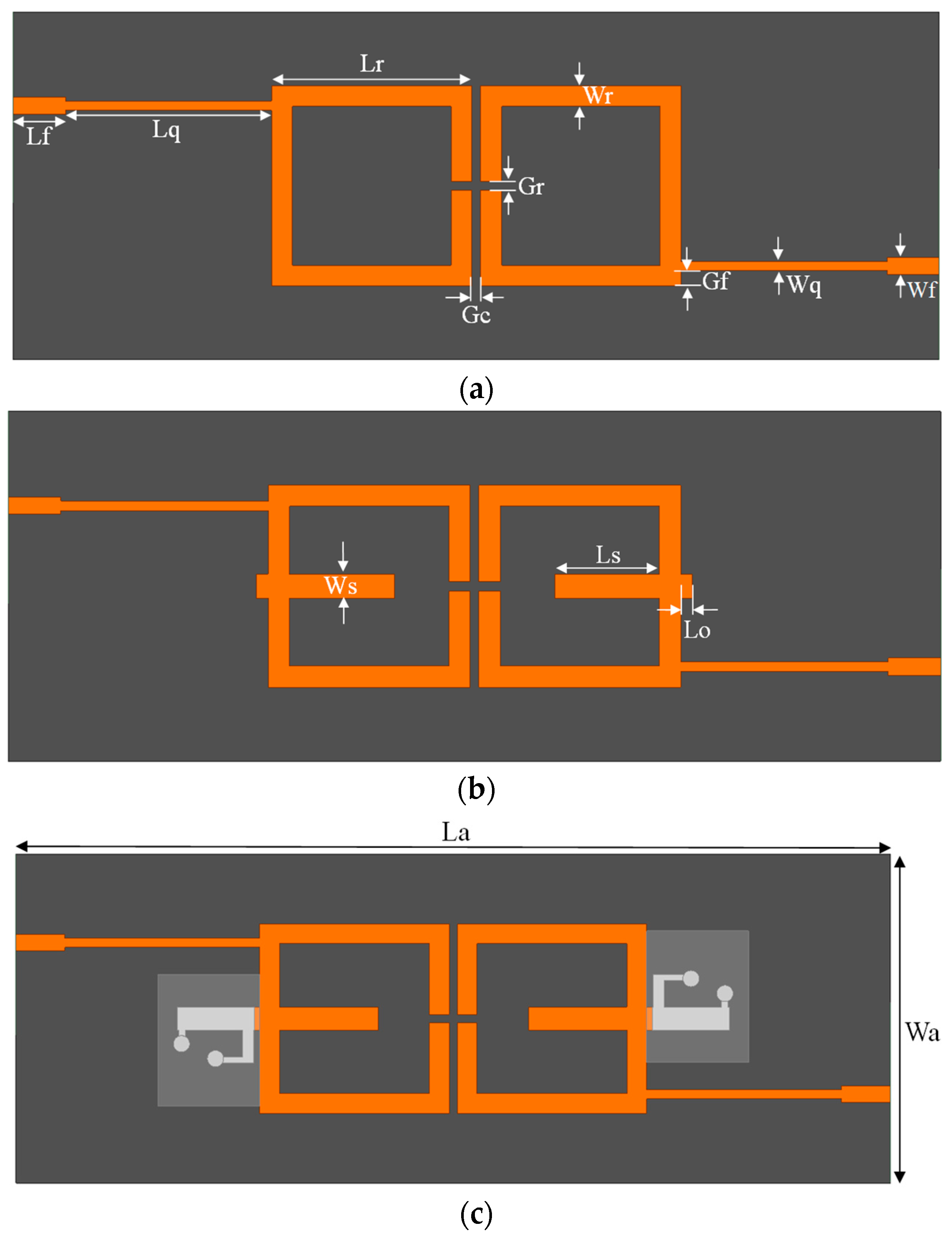

Figure 2.
Side view of the proposed filter.

Figure 3.
Simulated S21 of the proposed filter for: (a) different Lr; (b) different Ls; and (c) different Lc.
Figure 3.
Simulated S21 of the proposed filter for: (a) different Lr; (b) different Ls; and (c) different Lc.

Figure 4.
Simulated S-parameters of the proposed filter.
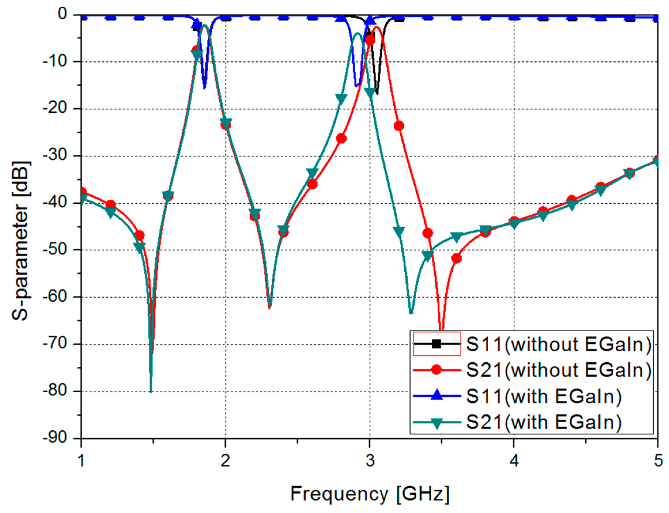
Figure 5.
Process of fabricating the microfluidic channel: (a) design; (b) 3D printing; (c) PDMS solidification; and (d) the fabricated microfluidic channel.
Figure 5.
Process of fabricating the microfluidic channel: (a) design; (b) 3D printing; (c) PDMS solidification; and (d) the fabricated microfluidic channel.

Figure 6.
Pictures of the fabricated proposed filter: (a) without EGaIn; (b) with EGaIn; and (c) in the process of injecting EGaIn.
Figure 6.
Pictures of the fabricated proposed filter: (a) without EGaIn; (b) with EGaIn; and (c) in the process of injecting EGaIn.
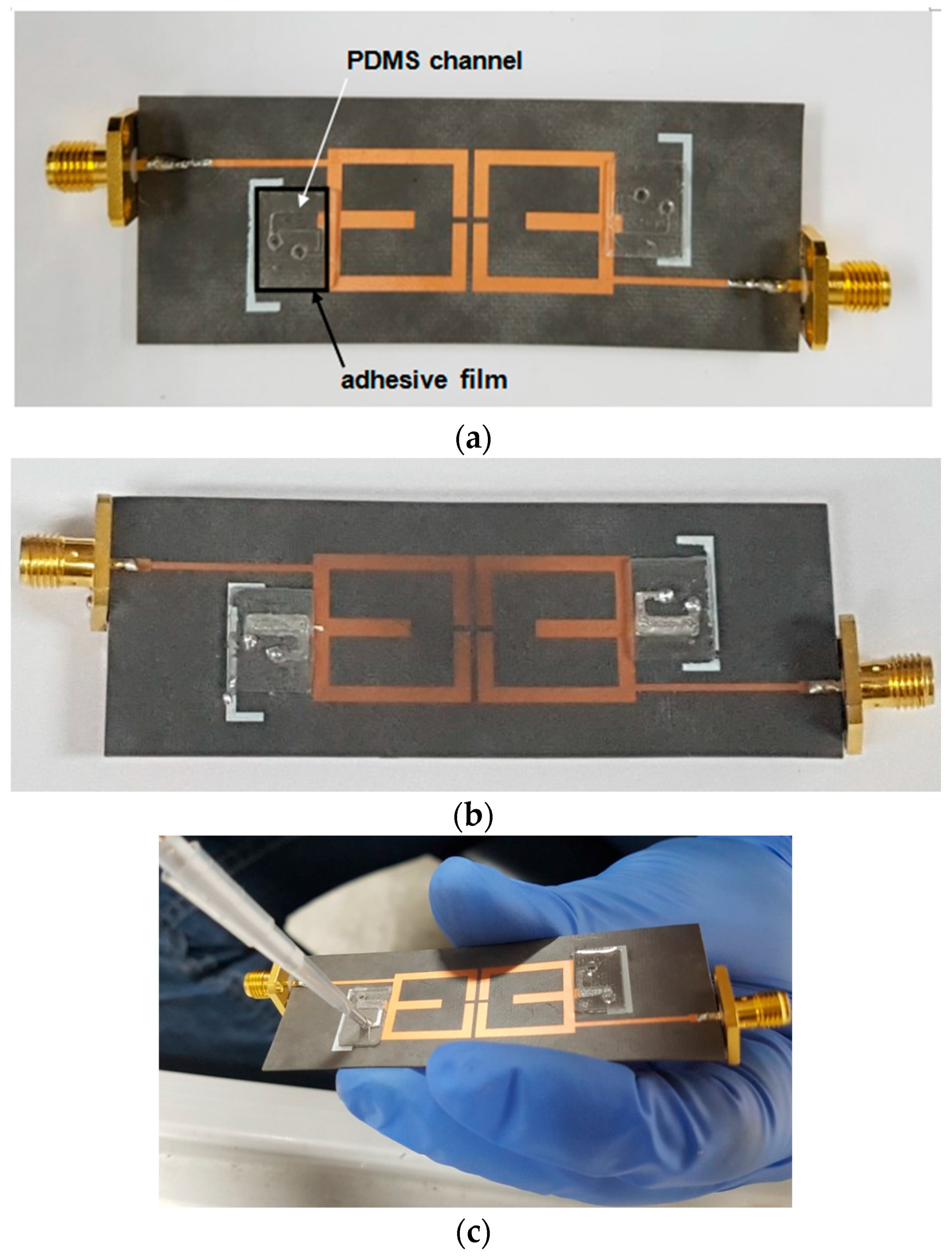
Figure 7.
(a) Measured S-parameters of the proposed filter without and with EGaIn and insertion loss without and with EGaIn (b) in odd mode; and (c) in even mode.
Figure 7.
(a) Measured S-parameters of the proposed filter without and with EGaIn and insertion loss without and with EGaIn (b) in odd mode; and (c) in even mode.

Table 1.
Summary of simulated and measured results of the proposed filter.
| Without EGaIn | With EGaIn | ||||
|---|---|---|---|---|---|
| Simulation | Measurement | Simulation | Measurement | ||
| Odd Mode | Resonant Freuqnecy (GHz) | 1.85 | 1.85 | 1.85 | 1.86 |
| Insertion Loss (dB) | 2.15 | 2.72 | 2.17 | 2.45 | |
| Fractional Bandwidth (%) | 4.32 | 4.34 | 4.32 | 4.3 | |
| Even Mode | Resonant Freuqnecy (GHz) | 3.05 | 3.06 | 2.9 | 2.98 |
| Insertion Loss (dB) | 2.57 | 3.21 | 3.9 | 2.93 | |
| Fractional Bandwidth (%) | 2.75 | 2.94 | 2.96 | 2.95 | |
Table 2.
Comparison table of the proposed filter performance with other liquid metal tunable filters.
Table 2.
Comparison table of the proposed filter performance with other liquid metal tunable filters.
| [18] | [24] | [25] | Proposed Work | |
|---|---|---|---|---|
| Filter type | Lowpass | Band-pass | Band-pass | Dual Band-pass |
| Insertion Loss (dB) | N/A | <3 | <1.5 | <2.72, <3.21 |
| Bandwidth (%) | N/A | 5 | 9.38 | 4.34, 2.95 |
| Tuning Range (%) | 38 | 25.3 | 14 | 2.7 |
| Number of band | Single Band | Single Band | Signle Band | Dual Band |
© 2017 by the authors. Licensee MDPI, Basel, Switzerland. This article is an open access article distributed under the terms and conditions of the Creative Commons Attribution (CC BY) license (http://creativecommons.org/licenses/by/4.0/).
Share and Cite
MDPI and ACS Style
Park, E.; Lim, D.; Lim, S. Dual-Band Band-Pass Filter with Fixed Low Band and Fluidically-Tunable High Band. Sensors 2017, 17, 1884. https://doi.org/10.3390/s17081884
AMA Style
Park E, Lim D, Lim S. Dual-Band Band-Pass Filter with Fixed Low Band and Fluidically-Tunable High Band. Sensors. 2017; 17(8):1884. https://doi.org/10.3390/s17081884
Chicago/Turabian StylePark, Eiyong, Daecheon Lim, and Sungjoon Lim. 2017. "Dual-Band Band-Pass Filter with Fixed Low Band and Fluidically-Tunable High Band" Sensors 17, no. 8: 1884. https://doi.org/10.3390/s17081884
Note that from the first issue of 2016, this journal uses article numbers instead of page numbers. See further details here.