A Grid Connected Photovoltaic Inverter with Battery-Supercapacitor Hybrid Energy Storage

Abstract
:1. Introduction
1.1. Present State of the Art
1.2. Literature Review
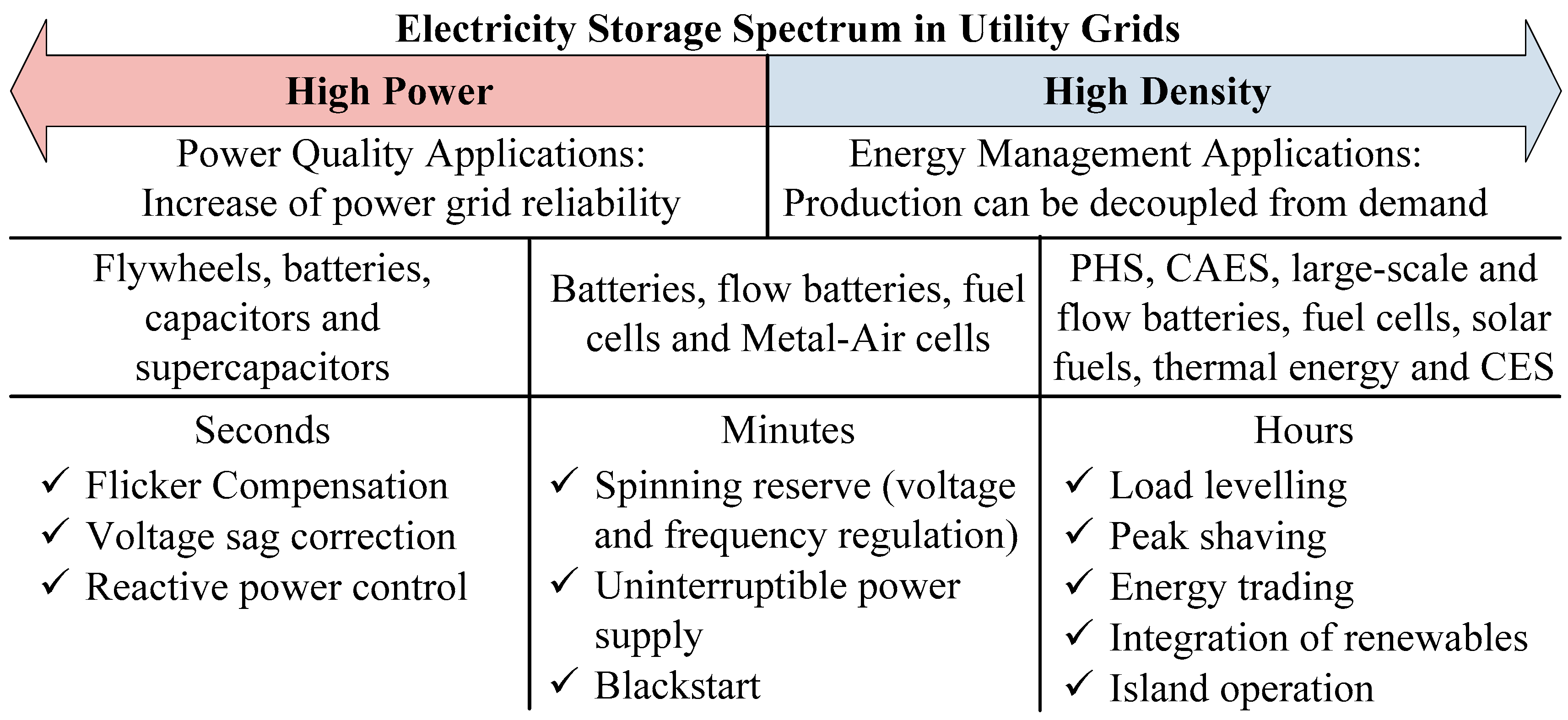
- Microgrids are the most used application for high power including energy management through global control with connection to grid when there is no energy stored. Some other applications are power injection regulation for tracking the forecasts, smoothing the fluctuating output power of the PV plant and power sharing.
- The trend when using ESS is to implement independent power stages for each power source, which means a boost stage for photovoltaics [30]. Photovoltaic inverters with two or more stages are usually implemented in the low-medium power range in order to boost the PV array voltage [31,32]. For higher power ranges, the boost stage is avoided as the PV arrays provide enough voltage and the efficiency is higher [33]. However, the energy management advantages introduced by an ESS require independent stages for each energy source in order to be optimized [34].
- Also, the control scheme is more flexible and robust when each decoupled stage introduces its degrees of freedom, to include all the electrical functions the converter is supposed to have. That is why most of the topologies include boost and DC/DC stages, including high power oriented ones, despite being worse. In addition, the efficiency of the boost stages could be optimized for the design [35].
- The main goal is usually to maintain the battery health, in addition to the particular application purpose. This is done using the supercapacitor for the sharp changes and developing control strategies that decrease the charge/discharge current rates of battery while maintaining a healthy state of charge (SOC) for both. These techniques also imply reduced current stress levels, less temperature and improved battery life span. Usually, the hybrid solution is done by using a low pass filter (LPF) which provides a high frequency reference for the supercapacitor and a low frequency reference for the battery.
1.3. Motivation and Objective
1.4. Innovative Contribution
2. Topology
3. Materials and Methods
4. HESS Sizing
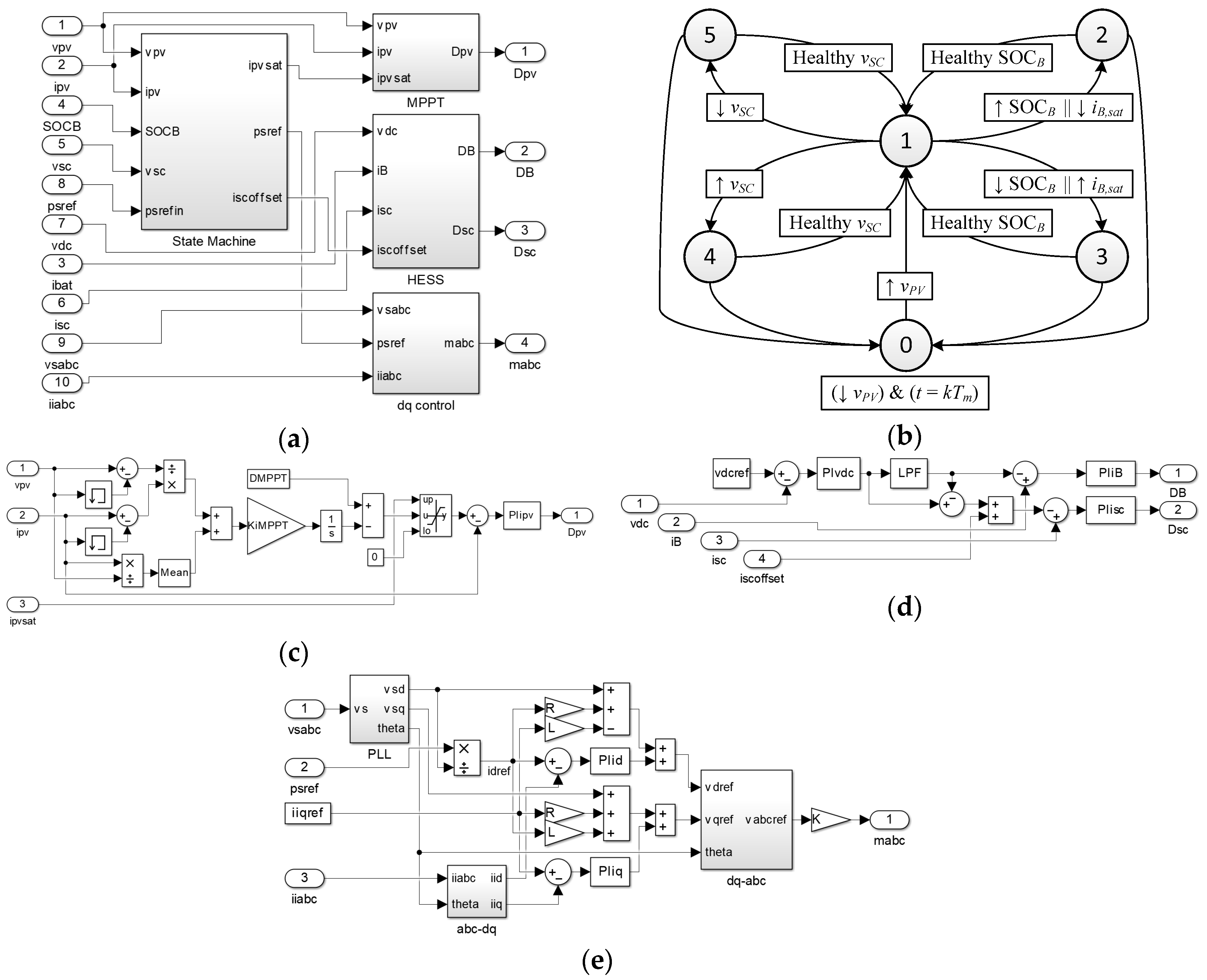
5. Control Logic
- The converter enters standby mode when the PV array has low irradiance, which could be evaluated via the PV voltage considering MPPT operation, and the management time interval starts.
- In normal operation mode, every parameter of the converter is working inside the good operating range, and subsequently, the power injected into the grid is the reference power in the interval. This mode is reached from standby when the irradiance is enough, and from the other states when the ESS recovers a good SOC range.
- The battery SOC has reached the top allowed level or the battery charging current becomes saturated. This means the PV generation is too high. In order to maintain the injected power reference, the system sets the reference power point tracking (RPPT) instead of the MPPT by saturating the PV boost current, iPV,sat. In case of high battery SOC, the RPPT is obtained for zero battery power flow and at the end of the management time interval, the PV boost stage operates on MPPT for the next ps,ref calculation in an optimistic way in order to force battery discharge. If the battery current is saturated, the RPPT is obtained to avoid current battery saturation.
- Battery SOC is at the minimum value or battery current is saturated at its maximum value. This is a critical state, where ps,ref must change before the end of the management time interval for zero or non-saturated battery power flow because of low PV irradiance. pS,ref is calculated in a pessimistic way for the next cycle.
- Supercapacitor has reached its top voltage. Negative power flow for the supercapacitor by adding a steady state negative offset, iSC,offset.
- Supercapacitor voltage is too low. Positive power flow for the supercapacitor by adding a steady state positive offset.
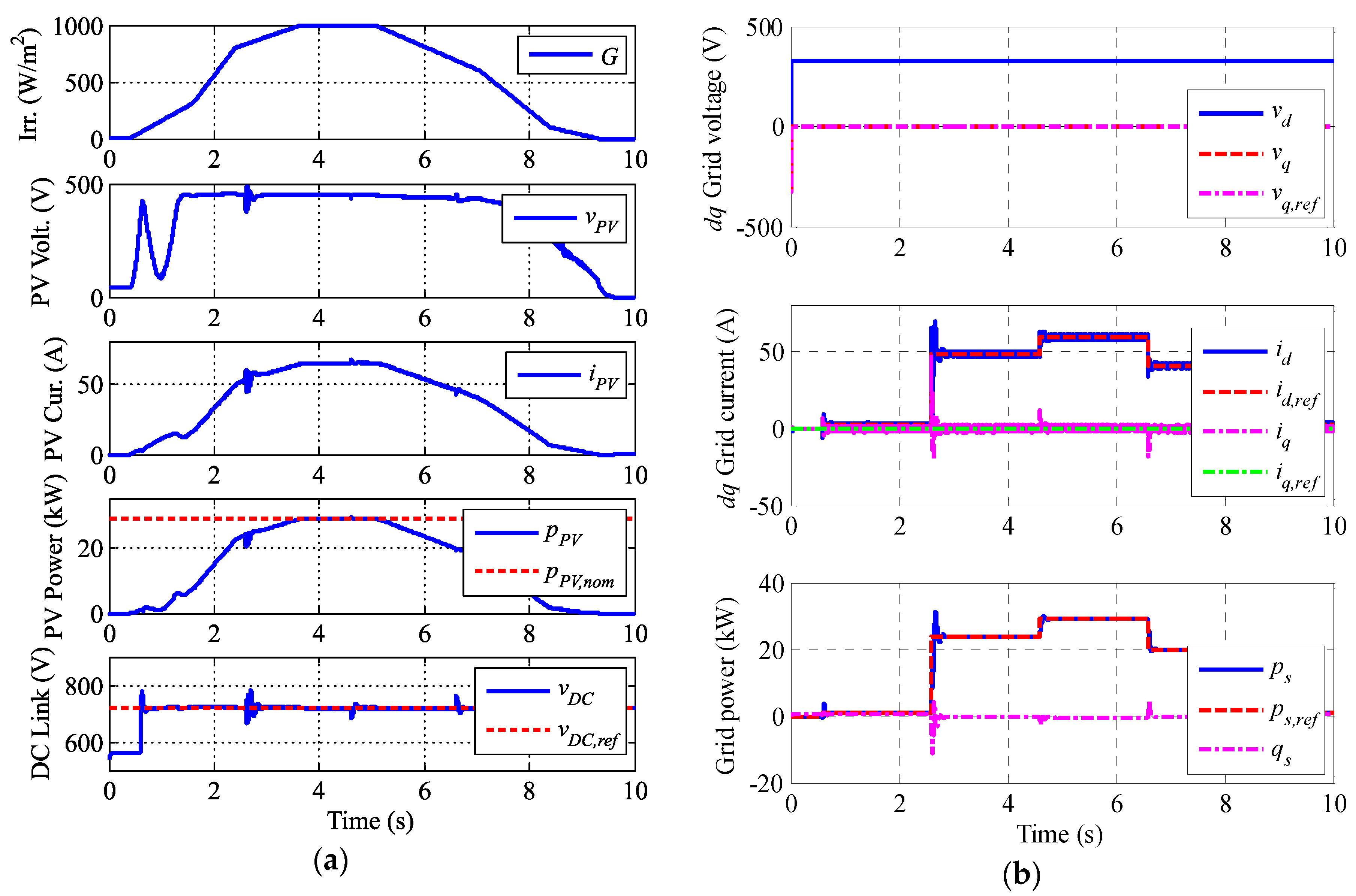
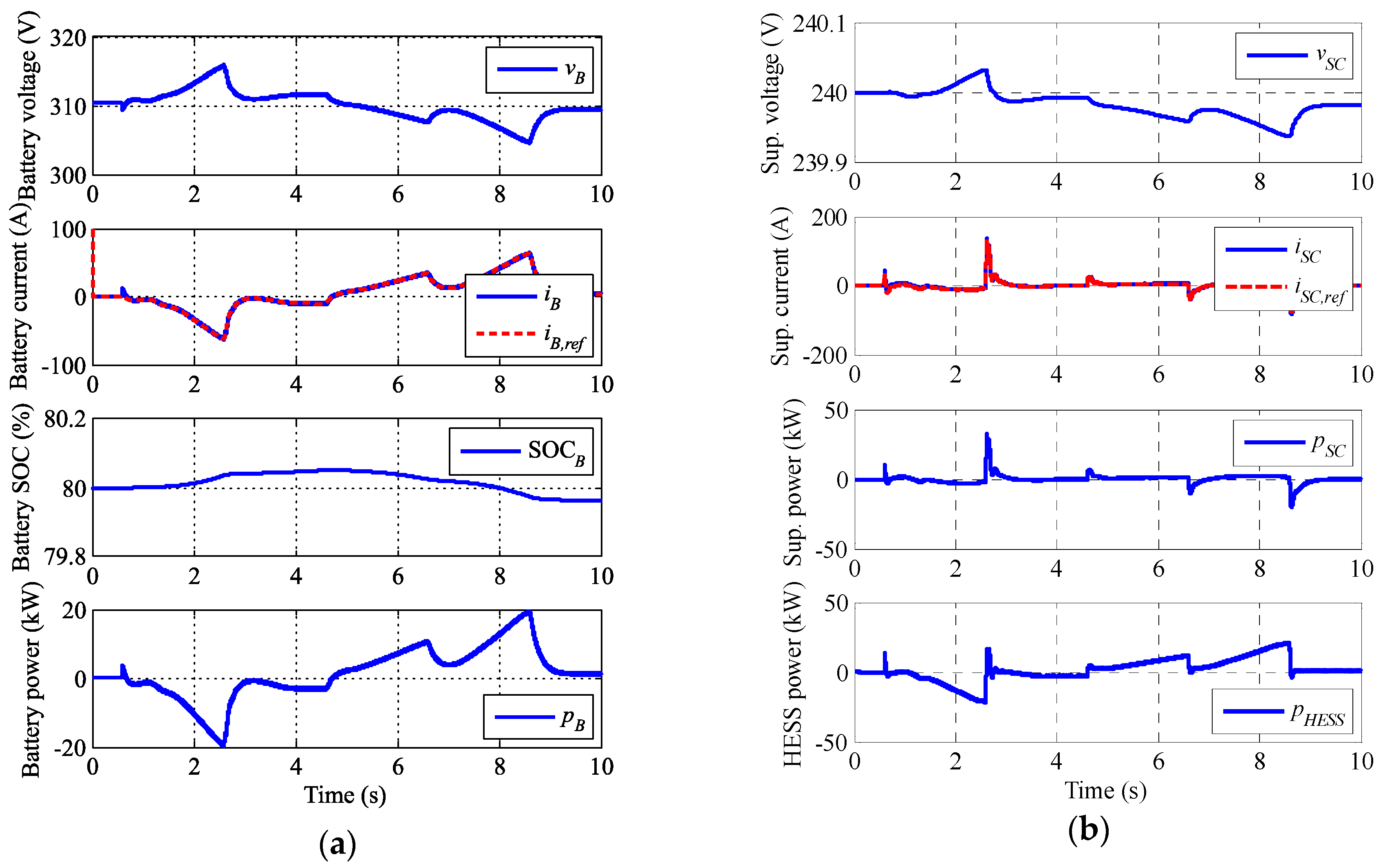
6. Simulation
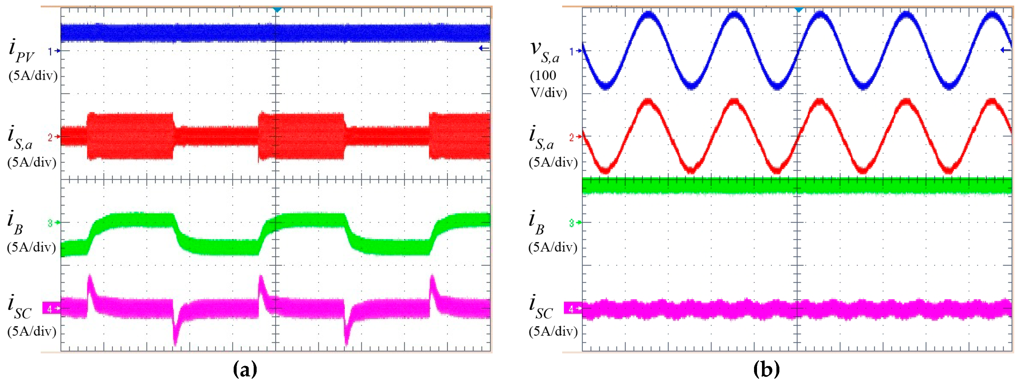
7. Experimental Results
8. Conclusions
Acknowledgments
Author Contributions
Conflicts of Interest
Acronyms
| AC | Alternating Current |
| B | Battery |
| CAES | Compressed Air Energy Storage |
| DC | Direct Current |
| DER | Distributed Energy Resource |
| dq | Direct-quadrature |
| ESS | Energy Storage Systems |
| HESS | Hybrid Energy Storage Systems |
| LPF | Low Pass Filter |
| MPPT | Maximum Power Point Tracking |
| PHS | Pumped Hydropower Storage |
| PI | Proportional Integral |
| PLL | Phase Locked Loop |
| PV | PhotoVoltaic |
| PWM | Pulse Width Modulation |
| RPPT | Reference Power Point Tracking |
| SC | SuperCapacitors |
| SOC | State Of Charge |
| THD | Total Harmonic Distortion |
| UPS | Uninterruptible Power Supply |
Nomenclature
| , , | Grid phases |
| ; ; | Inverter output filter capacitors |
| , | DC link capacitors |
| PV boost stage capacitor | |
| DC/DC battery converter duty cycle | |
| Boost converter duty cycle | |
| DC/DC supercapacitor converter duty cycle | |
| Battery ESS capacity | |
| Maximum ESS capacity needed for a certain design | |
| Minimum ESS capacity required for a certain design | |
| Supercapacitor ESS capacity | |
| Full ESS capacity | |
| Energy charge in the ESS | |
| sample pointer | |
| Grid direct reference current | |
| ; ; | Inverter output currents |
| PV current saturation for RPPT | |
| Grid quadrature reference current | |
| ; ; | Grid currents |
| Offset current term for the supercapacitor converter | |
| Battery current | |
| Grid dq current | |
| , | PV module current |
| Supercapacitor converter current | |
| cumulative pointer | |
| Equivalent grid filter indtor | |
| ; ; | Inverter output filter inductances (inverter side) |
| ; ; | Inverter output filter inductances (grid side) |
| DC/DC battery converter inductance | |
| Boost converter inductance | |
| Inverter output filter inductances (grid side) | |
| DC/DC supercapacitor converter inductance | |
| number of management time intervals | |
| time management interval pointer | |
| Inverter duty cycle | |
| number of samples inside a management time interval | |
| Middle point of the DC link | |
| Nminal power of the converter | |
| Reference active power set-point | |
| Battery power | |
| Photovoltaic generation power | |
| PV module power | |
| Grid injected power | |
| Super-capacitor power | |
| Equivalent grid filter resistance | |
| External measurement resistance for LEM transducers | |
| ; ; ; ; ; | Inverter switching signals |
| Boost converter switching signal | |
| ; | DC/DC battery converter switching signals |
| ; | DC/DC supercapacitor converter switching signals |
| Management time interval | |
| Sampling time | |
| Grid direct reference voltage | |
| DC link voltage reference value | |
| ; | Inverter output voltages |
| Grid quadrature reference voltage | |
| ; | Grid Voltages |
| Battery voltage | |
| Grid direct voltage | |
| DC link voltage | |
| Grid dq voltages | |
| PV module voltage | |
| Grid quadrature voltage | |
| Supercapacitor voltage | |
| Low-pass filter time constant |
References
- Chen, H.; Cong, T.; Yang, W.; Tan, C.; Li, Y.; Ding, Y. Progress in electrical energy storage system: A critical review. Prog. Natl. Sci. 2009, 19, 291–312. [Google Scholar] [CrossRef]
- Ippolito, M.G.; Telaretti, E.; Zizzo, G.; Graditi, G. A new device for the control and the connection to the grid of combined RES-based generators and electric storage systems. In Proceedings of the 4th International Conference on Clean Electrical Power: Renewable Energy Resources Impact, ICCEP 2013, Alghero, Italy, 11–13 June 2013; pp. 262–267. [Google Scholar]
- Xu, L.; Ruan, X.; Mao, C.; Zhang, B.; Luo, Y. An Improved Optimal Sizing Method for Wind-Solar-Battery Hybrid Power System. IEEE Trans. Sustain. Energy 2013, 4, 774–785. [Google Scholar]
- Zakeri, B.; Syri, S. Electrical energy storage systems: A comparative life cycle cost analysis. Renew. Sustain. Energy Rev. 2015, 42, 569–596. [Google Scholar] [CrossRef]
- Srivastava, A.; Kumar, A.; Schulz, N. Impact of Distributed Generations with Energy Storage Devices on the Electric Grid. IEEE Syst. J. 2012, 6, 110–117. [Google Scholar] [CrossRef]
- Meshram, S.; Agnihotri, G.; Gupta, S. Performance Analysis of Grid Integrated Hydro and Solar Based Hybrid Systems. Adv. Power Electron. 2013, 2013, 697049. [Google Scholar] [CrossRef]
- Kuperman, A.; Aharon, I. Battery–ultracapacitor hybrids for pulsed current loads: A review. Renew. Sustain. Energy Rev. 2011, 15, 981–992. [Google Scholar] [CrossRef]
- Guerrero-Martínez, M.A.; Romero-Cadaval, E.; González, F.B.; Montero, M.I.M.; Romera, E.G. Supercapacitors: Alternative Energy Storage Systems. Przegląd Elektrotechniczny 2009, 85, 188–195. [Google Scholar]
- Gao, L.; Dougal, R.; Liu, S. Power enhancement of an actively controlled battery/ultracapacitor hybrid. IEEE Trans. Power Electr. 2005, 20, 236–243. [Google Scholar] [CrossRef]
- Choi, M.; Kim, S.; Seo, S. Energy Management Optimization in a Battery/Supercapacitor Hybrid Energy Storage System. IEEE Trans. Smart Grid 2012, 3, 463–472. [Google Scholar] [CrossRef]
- Ongaro, F.; Saggini, S.; Mattavelli, P. Li-Ion Battery-Supercapacitor Hybrid Storage System for a Long Lifetime, Photovoltaic-Based Wireless Sensor Network. IEEE Transac. Power Electr. 2012, 27, 3944–3952. [Google Scholar] [CrossRef]
- Hredzak, B.; Agelidis, V.; Jang, M. A Model Predictive Control System for a Hybrid Battery-Ultracapacitor Power Source. IEEE Trans. Power Electr. 2014, 29, 1469–1479. [Google Scholar] [CrossRef]
- Kollimalla, S.; Mishra, M.; Narasamma, N. Design and Analysis of Novel Control Strategy for Battery and Supercapacitor Storage System. IEEE Trans. Sustain. Energy 2014, 5, 1137–1144. [Google Scholar] [CrossRef]
- Feng, X.; Gooi, H.; Chen, S. Hybrid Energy Storage with Multimode Fuzzy Power Allocator for PV Systems. IEEE Trans. Sustain. Energy 2014, 5, 389–397. [Google Scholar] [CrossRef]
- Glavin, M.; Hurley, W. Optimisation of a photovoltaic battery ultracapacitor hybrid energy storage system. Sol. Energy 2012, 86, 3009–3020. [Google Scholar] [CrossRef]
- Jung, H.; Wang, H.; Hu, T. Control design for robust tracking and smooth transition in power systems with battery/supercapacitor hybrid energy storage devices. J. Power Source 2014, 267, 566–575. [Google Scholar] [CrossRef]
- Benaouadj, M.; Aboubou, A.; Ayad, M.; Becherif, M. Nonlinear Flatness Control Applied to Supercapacitors Contribution in Hybrid Power Systems Using Photovoltaic Source and Batteries. Energy Procedia 2014, 50, 333–341. [Google Scholar] [CrossRef]
- Zhou, H.; Bhattacharya, T.; Tran, D.; Siew, T.; Khambadkone, A. Composite Energy Storage System Involving Battery and Ultracapacitor with Dynamic Energy Management in Microgrid Applications. IEEE Trans. Power Electr. 2011, 26, 923–930. [Google Scholar] [CrossRef]
- Lahyani, A.; Venet, P.; Guermazi, A.; Troudi, A. Battery/Supercapacitors Combination in Uninterruptible Power Supply (UPS). IEEE Trans. Power Electr. 2013, 28, 1509–1522. [Google Scholar] [CrossRef]
- Zhu, Y.; Zhuo, F.; Shi, H. Power management strategy research for a photovoltaic-hybrid energy storage system. In Proceedings of the 2013 IEEE ECCE Asia Downunder, Melbourne, Australia, 3–6 June 2013. [Google Scholar]
- Mendis, N.; Muttaqi, K.; Perera, S. Management of Battery-Supercapacitor Hybrid Energy Storage and Synchronous Condenser for Isolated Operation of PMSG Based Variable-Speed Wind Turbine Generating Systems. IEEE Trans. Smart Grid 2014, 5, 944–953. [Google Scholar] [CrossRef]
- Wang, G.; Ciobotaru, M.; Agelidis, V. Power Smoothing of Large Solar PV Plant Using Hybrid Energy Storage. IEEE Trans. Sustain. Energy 2014, 5, 834–842. [Google Scholar] [CrossRef]
- Wang, G.; Ciobotaru, M.; Agelidis, V. Power Management for Improved Dispatch of Utility-Scale PV Plants. IEEE Trans. Power Syst. 2016, 31, 2297–2306. [Google Scholar] [CrossRef]
- Etxeberria, A.; Vechiu, I.; Camblong, H.; Vinassa, J. Comparison of Sliding Mode and PI Control of a Hybrid Energy Storage System in a Microgrid Application. Energy Procedia 2011, 12, 966–974. [Google Scholar] [CrossRef]
- Jia, H.; Mu, Y.; Qi, Y. A statistical model to determine the capacity of battery–supercapacitor hybrid energy storage system in autonomous microgrid. Int. J. Electr. Power Energy Syst. 2014, 54, 516–524. [Google Scholar] [CrossRef]
- Choudar, A.; Boukhetala, D.; Barkat, S.; Brucker, J. A local energy management of a hybrid PV-storage based distributed generation for microgrids. Energy Conver. Manag. 2015, 90, 21–33. [Google Scholar] [CrossRef]
- Jiang, W.; Zhang, L.; Zhao, H.; Huang, H.; Hu, R. Research on power sharing strategy of hybrid energy storage system in photovoltaic power station based on multi-objective optimization. IET Renew. Power Gener. 2016, 10, 575–583. [Google Scholar] [CrossRef]
- Chatterjee, S.; Pandey, K.G. Thermoelectric cold-chain chests for storing/transporting vaccines in remote regions. Appl. Energy 2003, 76, 415–433. [Google Scholar] [CrossRef]
- Muñoz-García, M.A.; Moreda, G.P.; Raga-Arroyo, M.P.; Marín-González, O. Water harvesting for young trees using Peltier modules powered by photovoltaic solar energy. Comput. Electron. Agric. 2013, 93, 60–67. [Google Scholar] [CrossRef]
- Spertino, F.; Graditi, G. Power Conditioning Units in Grid-Connected Photovoltaic Systems: a Comparison with Different Technologies and Wide Range of Power Ratings. Sol. Energy 2014, 108, 219–229. [Google Scholar] [CrossRef]
- Nema, S.; Nema, R.K.; Agnihotri, G. Inverter Topologies and Control Structure in Photovoltaic Applications: A Review. J. Renew. Sustain. Energy 2011, 3, 012701. [Google Scholar] [CrossRef]
- Salas, V.; Olías, E. Overview of the State of Technique for PV Inverters used in Low Voltage Grid-Connected PV Systems: Inverters above 10 kW. Renew. Sustain. Energy Rev. 2011, 15, 1250–1257. [Google Scholar] [CrossRef]
- Romero-Cadaval, E.; Spagnuolo, G.; Franquelo, L.G.; Ramos-Paja, C.; Suntio, T.; Xiao, W. Grid-Connected Photovoltaic Generation Plants: Components and Operation. IEEE Ind. Electr. Mag. 2013, 7, 6–20. [Google Scholar] [CrossRef] [Green Version]
- Khaligh, A.; Li, Z. Battery, Ultracapacitor, Fuel Cell, and Hybrid Energy Storage Systems for Electric, Hybrid Electric, Fuel Cell, and Plug-In Hybrid Electric Vehicles: State of the Art. IEEE Trans. Veh. Technol. 2010, 59, 2806–2814. [Google Scholar] [CrossRef]
- Adinolfi, G.; Graditi, G.; Siano, P.; Piccolo, A. Multi-Objective Optimal Design of Photovoltaic Synchronous Boost Converters Assessing Efficiency, Reliability and Cost Savings. IEEE Transac. Ind. Inf. 2015, 11, 1038–1048. [Google Scholar] [CrossRef]
- P.O. 3.1 Programación de la Generación. Available online: http://www.boe.es/boe/dias/2015/12/19/pdfs/BOE-A-2015-13875.pdf (accessed on 9 August 2017).
- Esram, T.; Chapman, P.L. Comparison of Photovoltaic Array Maximum Power Point Tracking Techniques. IEEE Trans. Energy Conver. 2007, 22, 439–449. [Google Scholar] [CrossRef]
- Roncero-Clemente, C.; Romero-Cadaval, E.; Roncero-Sanchez, P.; Gonzalez-Romera, E. Comparison of two power flow control strategies for photovoltaic inverters. In Proceedings of the 38th Annual Conference on IEEE Industrial Electronics Society (IECON), Montreal, QC, Canada, 25–28 October 2012. [Google Scholar]
- Miñambres, V.; Milanés, M.I.; Vinagre, B.; Romero, E. Phase Locked Loop for Distorted Three-Phase Systems tested with a PI, a PID and a Fractional PI. Przegląd Elektrotechniczny 2009, 10, 201–207. [Google Scholar]
- Hamza, K.E.; Linda, H.; Cherif, L. LCL filter design with passive damping for photovoltaic grid connected systems. In Proceedings of the 6th International Renewable Energy Congress (IREC), Sousse, Tunisia, 24–26 March 2015. [Google Scholar]
- IEEE. IEEE Std 1547: IEEE Standard for Interconnecting Distributed Resources With the Electric Power System; IEEE: New York, NY, USA, 2003. [Google Scholar]
- IEC. IEC 61727 ed2.0: Photovoltaic (PV) Systems–Characteristics of the Utility Interface; IEC: Geneva, Switzerland, 2001. [Google Scholar]


| Paper | [9] | [10] | [11] | [12] | [13] | [14] | [15] | [16] | [17] |
|---|---|---|---|---|---|---|---|---|---|
| Application | Pulse-operated power systems | Load supply | Energy harvesting | Load supply | Load supply | Load supply | Load supply | Load supply | Load supply |
| System | DC | DC | DC | DC | DC | DC + 3~Alternating Current (AC) | DC | DC | DC |
| Topology | Active Hybrid Bidirectional DCDC | Bidirectional DCDC | PV Boost + Bidirectional DCDC | Bidirectional DCDC | PV Boost Bidirectional DCDC | PV Boost + Bidirectional DCDC + 3~Inverter | PV Boost + Bidirectional DCDC | Bidirectional DCDC | PV Boost + Bidirectional DCDC |
| Rated Power | 132 W | 500 W | 5 W | 50 W | 100 W | 1 kW | 50 W | 100 W | 2 kW |
| Comparison | Passive vs. Active hybrid | Napoli vs. MIAD | - | - | - | LPF vs. Haar wavelet vs. Fuzzy | - | - | ESS vs. HESS |
| Sizing | - | - | Statistical analysis | - | - | - | Optimization flowchart | - | - |
| Control | Proportional Integral (PI) | Multiplicative-increase-additive-decrease (MIAD) | State machine | Predictive control | PI with LPF | Multimode fuzzy-logic power allocator | - | state-space averaged model | Flatness approach |
| Goals | More power Lower battery temperature Longer battery lifetime | Minimization of the battery current fluctuation and SC energy loss | Increase battery lifetime | Battery current and state of charge SC into the limits | Improve the life span and reduce the current stresses on battery | Avoid depleting or saturating the two components Relaxing the stress on batteries | Healthy SOC | Control design | Role of SC as a transient power source |
| Paper | [18] | [19] | [20] | [21] | [22,23] | [24] | [25] | [26] | [27] |
|---|---|---|---|---|---|---|---|---|---|
| Application | Microgrids | UPS | Hybrid microgrid | Remote Area Power Supply | Grid-connected photovoltaic | Microgrid | Microgrid | Microgrid | Power sharing |
| System | DC | DC | DC + 3~AC | DC + 3~AC | DC + 3~AC | DC + 3~AC | DC + 3~AC | DC + 3~AC | |
| Topology | Dual active bridge | Bidirectional DCDC | PV Boost + 3~Inverter and Bidirectional DCDC + 3~Inverter | Wind Rectifier-Boost + Bidirectional DCDC + 3~Inverter | PV Boost + Bidirectional DCDC + 3~Inverter | Bidirectional DCDC + 3~Inverter | PV Boost + 3~Inverter and Bidirectional DCDC + 3~Inverter | PV Boost + Bidirectional DCDC + 3~Inverter | Bidirectional DCDC + 3~Inverter |
| Rated Power | 5 kW Modular | 500 kVA | 30 kW | 25 kW | 1 MW | 10 kW | 60 kW | 100 kW | 4 MW |
| Comparison | - | - | Different capacities | LPF | - | two-loop PI control and PI sliding mode | - | - | Multi-objective optimization problem (MOP), LPF and LUT |
| Sizing | - | Backup time | Power grading | Equations | SC as 1/5 battery | - | Monte Carlo capacity model | - | - |
| Control | LPF Energy management | Power sharing | State of charge with load control | Energy management algorithm | Semischeduled generation | Sliding mode | Hysteretic loop | PI controllers and Direct Power Control | Linear weighted summation algorithm |
| Goals | Energy balance with renewables | Optimal SC-battery combination vs SC cost | Power balance and ESS in healthy state | Robust voltage and frequency regulation Effective HESS management | Avoid low power level battery operation | Using a nonlinear controller | Extend the battery lifetime by avoiding small cycles | Maintain the grid power demand coming from the grid operator | Optimization of the energy loss and state of charge of the SC |
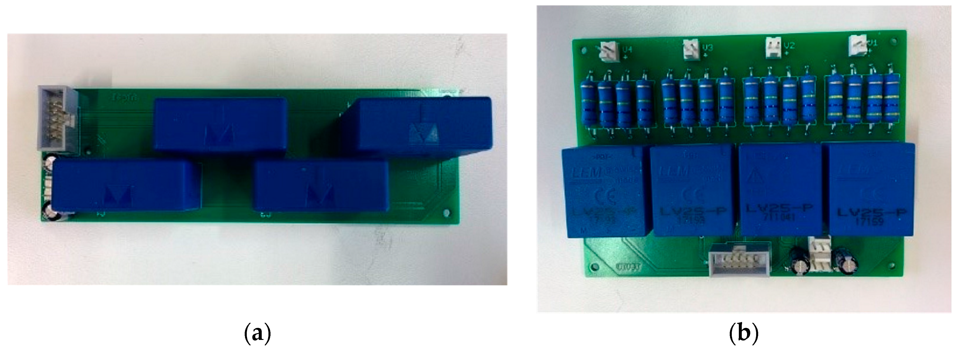
| Current Transducers | Specification | Voltage Transducers |
|---|---|---|
| 0 ... ±100 A | Measuring range | 0 ... ±14 mA (10 mA/500 V) |
| 25 mA | Secondary nominal current rms | 25 mA |
| ±12 ... 15 V | Supply voltage | ±15 V (±5%) |
| 200 kHz | Frequency bandwith | 200 kHz |
| 2.5 kV rms | Isolation | 2.5 kV rms |
| 1:2000 | Conversion ratio | 2500:1000 |
| ±0.9% | Accuracy | ±0.9% |
| −40 °C to 85 °C | Operating temperature | 0 °C to 70 °C |
| Symbol | Value | Symbol | Value | Symbol | Value |
|---|---|---|---|---|---|
| pPV,nom | 30 kW | ESSCa,B | 3 kWh | LPV | 10 mH |
| Tm | 2 s | ESSCa,SC | 0.3 kWh | LB = LSC | 20 mH |
| τ | 0.2 s | PWM | 5 kHz | LCL | 5 mH, 10 μF, 5 mH |
| vDC,ref | 720 V | C1, C2 | 2.2 mF | CSC | 37.5 F |
© 2017 by the authors. Licensee MDPI, Basel, Switzerland. This article is an open access article distributed under the terms and conditions of the Creative Commons Attribution (CC BY) license (http://creativecommons.org/licenses/by/4.0/).
Share and Cite
Miñambres-Marcos, V.M.; Guerrero-Martínez, M.Á.; Barrero-González, F.; Milanés-Montero, M.I. A Grid Connected Photovoltaic Inverter with Battery-Supercapacitor Hybrid Energy Storage. Sensors 2017, 17, 1856. https://doi.org/10.3390/s17081856
Miñambres-Marcos VM, Guerrero-Martínez MÁ, Barrero-González F, Milanés-Montero MI. A Grid Connected Photovoltaic Inverter with Battery-Supercapacitor Hybrid Energy Storage. Sensors. 2017; 17(8):1856. https://doi.org/10.3390/s17081856
Chicago/Turabian StyleMiñambres-Marcos, Víctor Manuel, Miguel Ángel Guerrero-Martínez, Fermín Barrero-González, and María Isabel Milanés-Montero. 2017. "A Grid Connected Photovoltaic Inverter with Battery-Supercapacitor Hybrid Energy Storage" Sensors 17, no. 8: 1856. https://doi.org/10.3390/s17081856