
Real-Time GNSS-Based Attitude Determination in the Measurement Domain

Abstract
:1. Introduction
2. GNSS Attitude Resolution Model in the Measurement Domain
3. AD Based on PAR
3.1. Float Solutions of AD
3.2. Attitude and Ambiguity Fixing
4. Experiment and Analysis
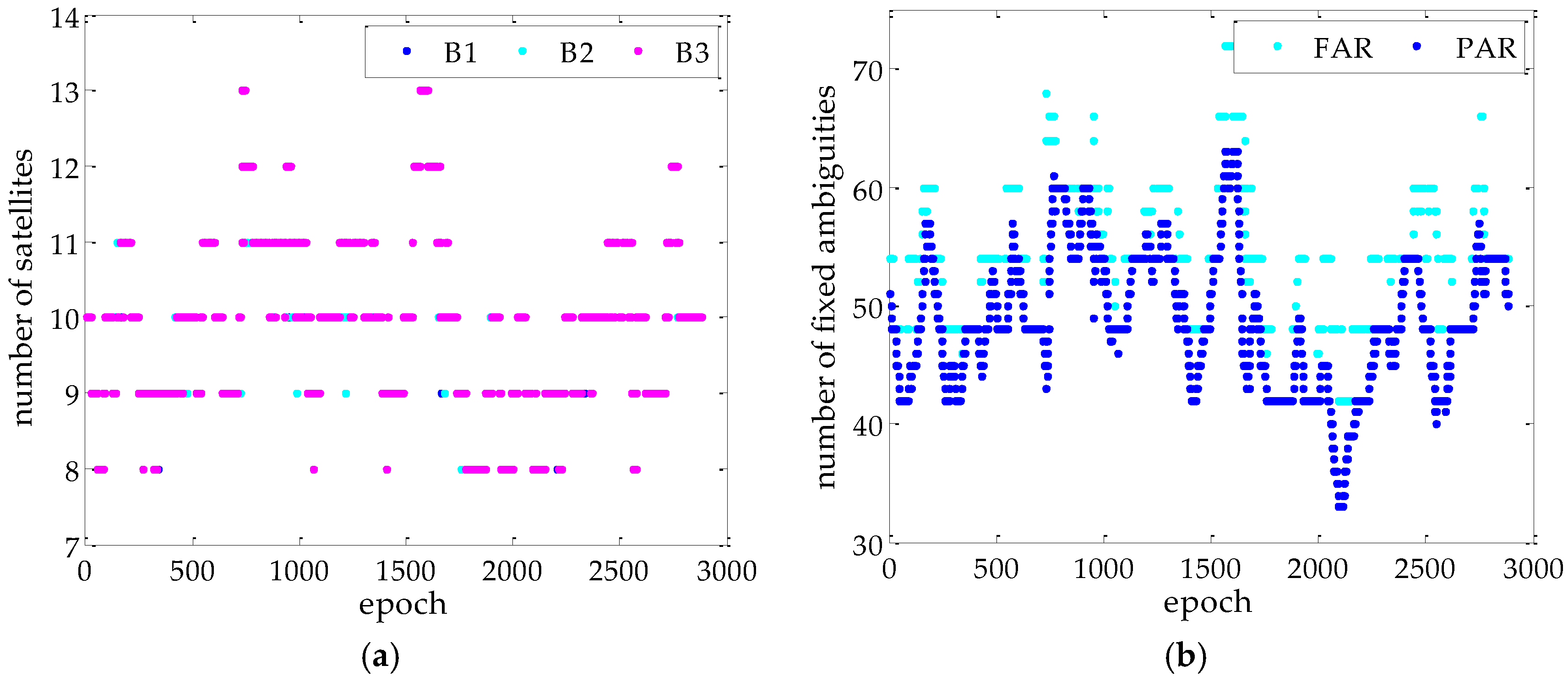
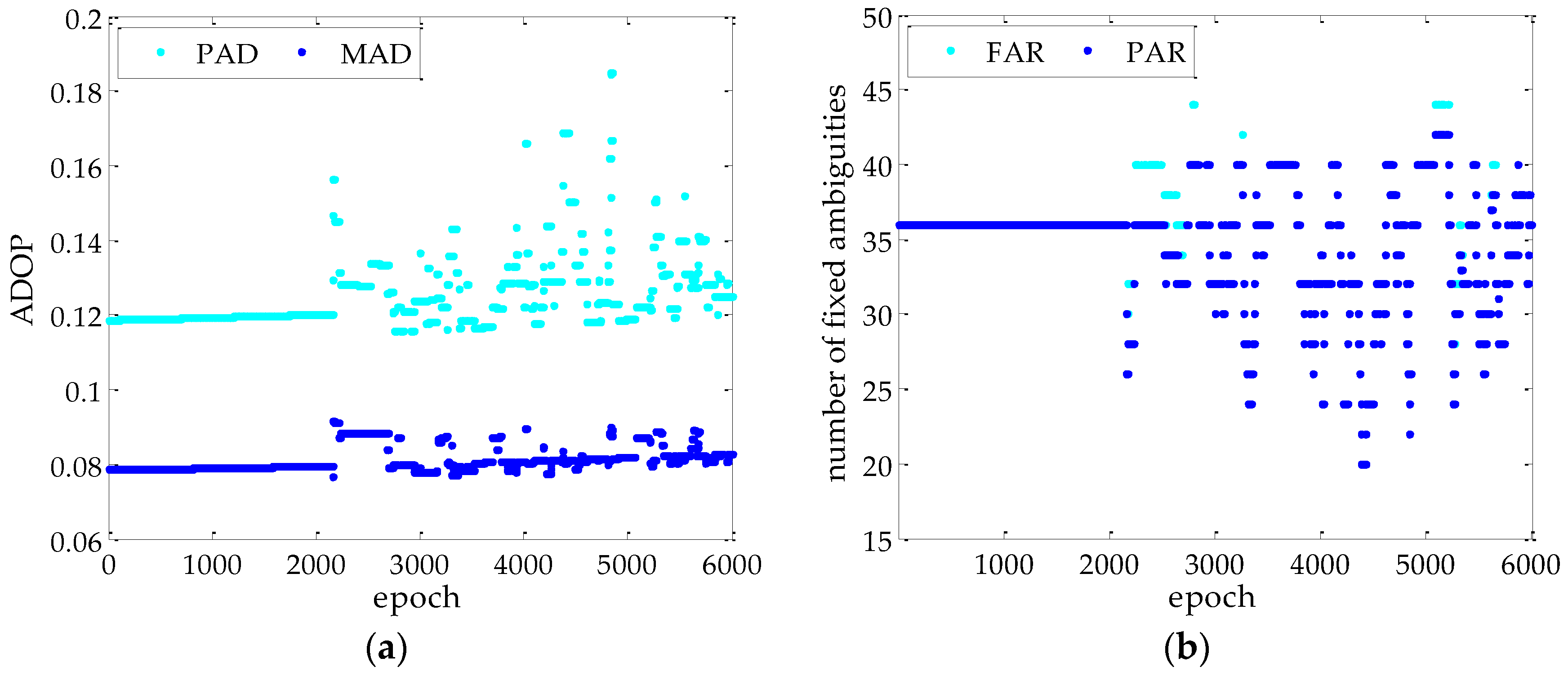
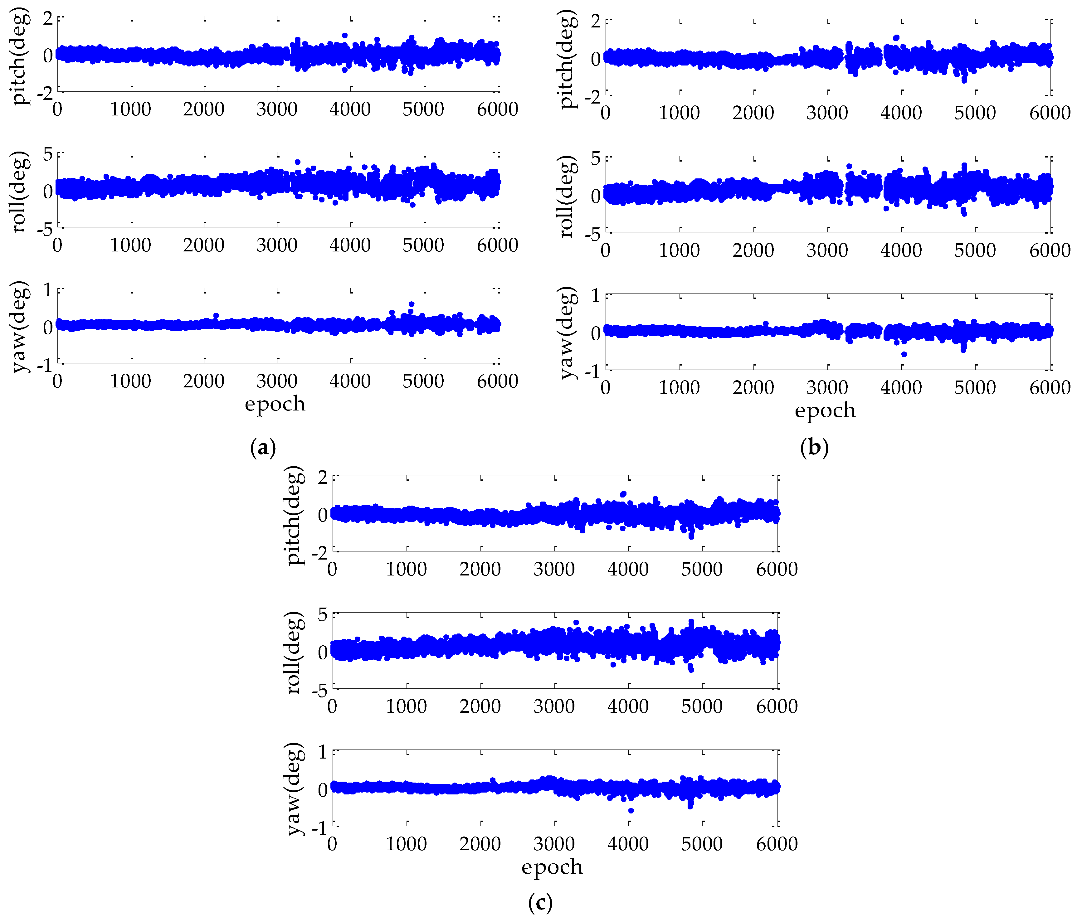
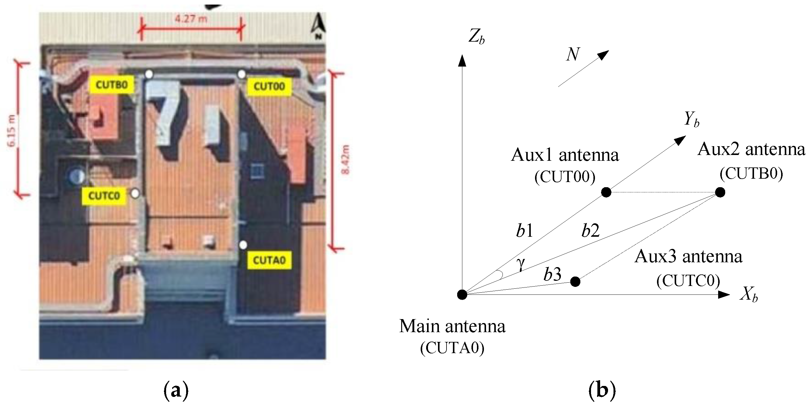
4.1. Static Experiment
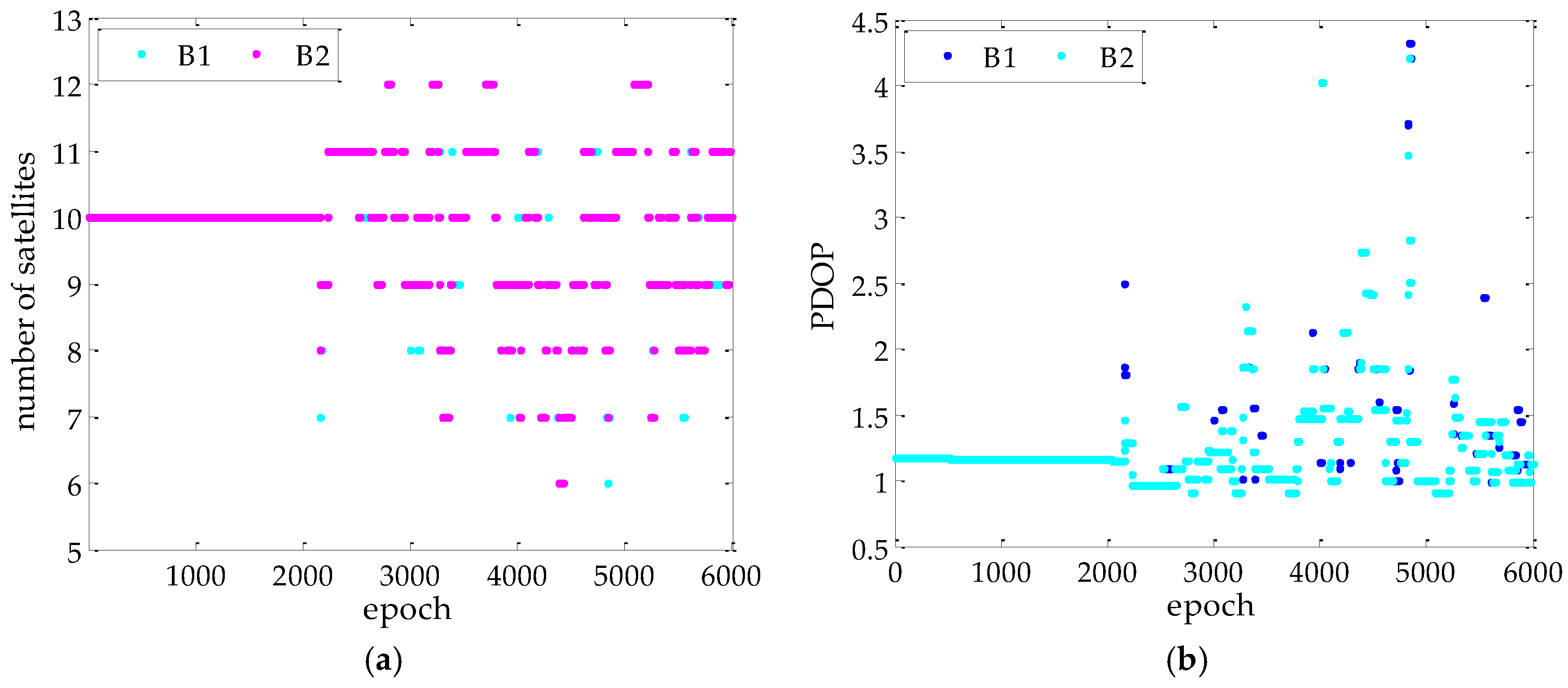
4.2. Kinematic Experiment
5. Conclusions
Acknowledgments
Author Contributions
Conflicts of Interest
References
- Giorgi, G.; Teunissen, P.J.; Verhagen, S.; Buist, P.J. Testing a new multivariate GNSS carrier phase attitude determination method for remote sensing platforms. Adv. Space Res. 2010, 46, 118–129. [Google Scholar] [CrossRef]
- Psiaki, M.L. Batch algorithm for global-positioning system attitude determination and integer ambiguity resolution. J. Guid. Control Dyn. 2006, 29, 1070–1079. [Google Scholar] [CrossRef]
- Li, Y.; Zhang, K.; Roberts, C.; Murata, M. On-the-fly GPS-based attitude determination using single- and double-differenced carrier phase measurements. GPS Solut. 2004, 8, 93–102. [Google Scholar] [CrossRef]
- Teunissen, P.J.; Giorgi, G.; Buist, P.J. Testing of a new single-frequency GNSS carrier phase attitude determination method: Land, ship and aircraft experiments. GPS Solut. 2011, 15, 15–28. [Google Scholar] [CrossRef]
- Giorgi, G.; Teunissen, P.J.; Gourlay, T.P. Instantaneous Global Navigation Satellite System (GNSS)-based attitude determination for maritime applications. IEEE J. Ocean. Eng. 2012, 37, 348–362. [Google Scholar] [CrossRef]
- Sabatini, R.; Rodríguez, L.; Kaharkar, A.; Bartel, C.; Shaid, T. Carrier-phase GNSS attitude determination and control system for unmanned aerial vehicle application. J. Aeronaut. Aero. Eng. 2012, 2, 297–322. [Google Scholar]
- Zhu, J.; Li, T.; Wang, J.; Hu, X.; Wu, M. Rate-gyro-integral constraint for ambiguity resolution in GNSS attitude determination applications. Sensors 2013, 13, 7979–7999. [Google Scholar] [CrossRef] [PubMed]
- Axelrad, P.; Behre, P.C. Satellite attitude determination based on GPS signal-to-noise ratio. Proc. IEEE 1999, 87, 133–144. [Google Scholar] [CrossRef]
- Psiaki, M.L.; Powell, S.P.; Kinter, P.M.J. The accuracy of the GPS-derived acceleration vector, a novel attitude reference. In Proceedings of the AIAA Guidance, Navigation, and Control Conference, Portland, OR, USA, 9–11 August 1999; pp. 751–760.
- Capuano, V.; Botteron, C.; Farine, P.A. GNSS based attitude determination for nanosatellites. In Proceedings of the 2nd IAA Conference on Dynamics and Control of Space Systems (DYCOSS), Rome, Italy, 24–26 March 2014; pp. 1–19.
- Wang, C.; Walker, R.A.; Moody, M.P. Single antenna attitude algorithm for non-uniform antenna gain patterns. J. Spacecr. Rockets 2007, 44, 221–229. [Google Scholar] [CrossRef] [Green Version]
- Cohen, C.E. Attitude Determination Using GPS. Ph.D. Thesis, Stanford University, Stanford, CA, USA, 1992. [Google Scholar]
- Cohen, C.E.; Cobb, H.S.; Parkinson, B.W. Two studies of high performance attitude determination using GPS: Generalizing Wahba’s problem for high output rates and evaluation of static accuracy using a theodolite. In Proceedings of the 5th International Technical Meeting of the Satellite Division of the Institute of Navigation (ION GPS 1992), Albuquerque, NM, USA, 16–18 September 1992; pp. 1197–1203.
- Lu, G. Development of a GPS Multi-Antenna System for Attitude Determination. Ph.D. Thesis, University of Calgary, Calgary, AB, Canada, 1995. [Google Scholar]
- Giorgi, G.; Verhagen, S.; Buist, P.J.; Teunissen, P.J.G. GNSS-based attitude determination: Aerospace and formation flying. Inside GNSS 2011, 6, 62–71. [Google Scholar]
- Cannon, M.E.; Sun, H.; Owen, T.E.; Meindl, M.A. Assessment of a non-dedicated GPS receiver system for precise airborne attitude determination. In Proceedings of the 7th International Technical Meeting of the Satellite Division of The Institute of Navigation (ION GPS 1994), Salt Lake, UT, USA, 20–23 September 1994; pp. 645–654.
- Wang, B.; Deng, Z.; Wang, S.; Fu, M. A motion-based integer ambiguity resolution method for attitude determination using the global positioning system (GPS). Meas. Sci. Technol. 2010, 21, 719–725. [Google Scholar] [CrossRef]
- Gong, A.; Zhao, X.; Pang, C.; Duan, R.; Wang, Y. GNSS single frequency, single epoch reliable attitude determination method with baseline vector constraint. Sensors 2015, 15, 30093–30103. [Google Scholar] [CrossRef] [PubMed]
- Shuster, M.D. Approximate algorithms for fast optimal attitude computation. In Proceedings of the AIAA Guidance and Control Conference, Palo Alto, CA, USA, 7–9 August 1978; pp. 88–95.
- Markley, F.L. Attitude determination using vector observations and the singular value decomposition. J. Astronaut. Sci. 1987, 38, 245–258. [Google Scholar]
- Markley, F.L.; Landis, F. Attitude determination from vector observations: A fast optimal matrix algorithm. J. Astronaut. Sci. 1993, 41, 261–280. [Google Scholar]
- Baritzhack, I.Y.; Montgomery, P.Y.; Garrick, J.C. Algorithms for attitude determination using the global positioning system. J. Guid. Control Dyn. 1998, 21, 846–852. [Google Scholar] [CrossRef]
- Graas, F.V.; Braasch, M. GPS interferometric attitude and heading determination: Initial flight test results. Navigation 1991, 38, 297–316. [Google Scholar] [CrossRef]
- Cohen, C.E. Attitude Determination. Global Positioning System: Theory and Applications II; Parkinson, B.W., Spilker, J.J., Eds.; Progress in Astronautics and Aeronautics, AIAA: Washington, DC, USA, 1996; pp. 519–538. [Google Scholar]
- Nadler, A.; Baritzhack, I.Y.; Weiss, H. Iterative algorithm for attitude estimation using global positioning system phase measurements. J. Guid. Control Dyn. 2001, 24, 983–990. [Google Scholar] [CrossRef]
- Park, F.C.; Kim, J.; Kee, C. Geometric descent algorithms for attitude determination using the global positioning system. J. Guid. Control Dyn. 2000, 23, 26–33. [Google Scholar] [CrossRef]
- Li, Y.; Murata, M.; Sun, B.X. New approach to attitude determination using global positioning system carrier phase measurement. J. Guid. Control Dyn. 2002, 25, 130–136. [Google Scholar] [CrossRef]
- Cheng, J.; Wang, J.; Zhao, L. A direct attitude determination approach based on GPS double-difference carrier phase measurements. J. Appl. Math. 2014, 2014, 548083. [Google Scholar] [CrossRef]
- Giorgi, G.; Teunissen, P.J.G. Carrier phase GNSS attitude determination with the multivariate constrained LAMBDA method. In Proceedings of the IEEE-AIAA Aerospace Conference, Big Sky, MT, USA, 6–13 March 2010; pp. 1–12.
- Verhagen, S.; Odijk, D.; Teunissen, P.J.G.; Huisman, T. Performance improvement with low-cost multi-GNSS receivers. In Proceedings of the 5th ESA Workshop on Satellite Navigation Technologies and European Workshop on GNSS Signals and Signal Processing (NAVITEC), Noordwijk, The Netherlands, 8–10 December 2010; pp. 1–8.
- Li, L.; Li, Z.; Yuan, H.; Wang, L.; Hou, Y. Integrity monitoring-based ratio test for GNSS integer ambiguity validation. GPS Solut. 2016, 20, 573–585. [Google Scholar] [CrossRef]
- Teunissen, P.J.G.; Joosten, P.; Tuberius, C.C.J.M. Geometry-free ambiguity success rates in case of partial fixing. In Proceedings of the 1999 National Technical Meeting of the Institute of Navigation, San Diego, CA, USA, 25–27 January 1999; pp. 201–207.
- Teunissen, P.J.G. GNSS ambiguity bootstrapping: Theory and applications. In Proceedings of the International Symposium on Kinematic Systems in Geodesy, Geomatics and Navigation, Banff, AB, Canada, 5–8 June 2001; pp. 246–254.
- Teunissen, P.J.G. A-PPP: Array-aided precise point positioning with Global Navigation Satellite Systems. IEEE Trans. Signal. Process. 2012, 60, 2870–2881. [Google Scholar] [CrossRef]
- Alban, S. Design and Performance of a Robust GPS/INS Attitude System for Automobile Applications. Ph.D. Thesis, Stanford University, Stanford, CA, USA, 2004. [Google Scholar]
- Han, S. Quality-control issues relating to instantaneous ambiguity resolution for real-time GPS kinematic positioning. J. Geod. 1997, 71, 351–361. [Google Scholar] [CrossRef]
- Nadarajah, N.; Teunissen, P.J.G. Instantaneous BeiDou-GPS attitude determination: A performance analysis. Adv. Space Res. 2014, 54, 851–862. [Google Scholar] [CrossRef]
- Teunissen, P.J.G. The least-squares ambiguity decorrelation adjustment: A method for fast GPS integer ambiguity estimation. J. Geod. 1995, 70, 65–82. [Google Scholar] [CrossRef]
- Parkins, A. Increasing GNSS RTK availability with a new single-epoch batch partial ambiguity resolution algorithm. GPS Solut. 2011, 15, 391–402. [Google Scholar] [CrossRef]
- Li, P.; Zhang, X. Precise point positioning with partial ambiguity fixing. Sensors 2015, 15, 13627–13643. [Google Scholar] [CrossRef] [PubMed]
- Teunissen, P.J.G. Success probability of integer GPS ambiguity rounding and bootstrapping. J. Geod. 1998, 72, 606–612. [Google Scholar] [CrossRef]
- Teunissen, P.J.G. An optimality property of the integer least-squares estimator. J. Geod. 1999, 73, 587–593. [Google Scholar] [CrossRef]
- Li, L.; Jia, C.; Zhao, L.; Yang, F.; Li, Z. Integrity monitoring-based ambiguity validation for triple-carrier ambiguity resolution. GPS Solut. 2016. [Google Scholar] [CrossRef]
- Teunissen, P.J.G.; Verhagen, S. The GNSS ambiguity ratio-test revisited: A better way of using it. Surv. Rev. 2009, 41, 138–151. [Google Scholar] [CrossRef]
- Teunissen, P.J.G. Penalized GNSS ambiguity resolution. J. Geod. 2004, 78, 235–244. [Google Scholar] [CrossRef]
- Verhagen, S.; Teunissen, P.J.G. New global navigation satellite system ambiguity resolution method compared to existing approaches. J. Guid. Control Dyn. 2006, 29, 981–991. [Google Scholar] [CrossRef]
- Curtin GNSS Research Centre. Available online: http://saegnss2.curtin.edu.au/ldc/ (accessed on 16 June 2016).


| Test Type | Baseline Coordinate in BFF (m) | Baseline Length (m) | Baseline Number |
|---|---|---|---|
| Static | b1 (0, 8.42, 0) b2 (4.27, 8.45, 0) b3 (5.23, 2.38, −0.19) | 8.42 9.47 5.75 | 3 |
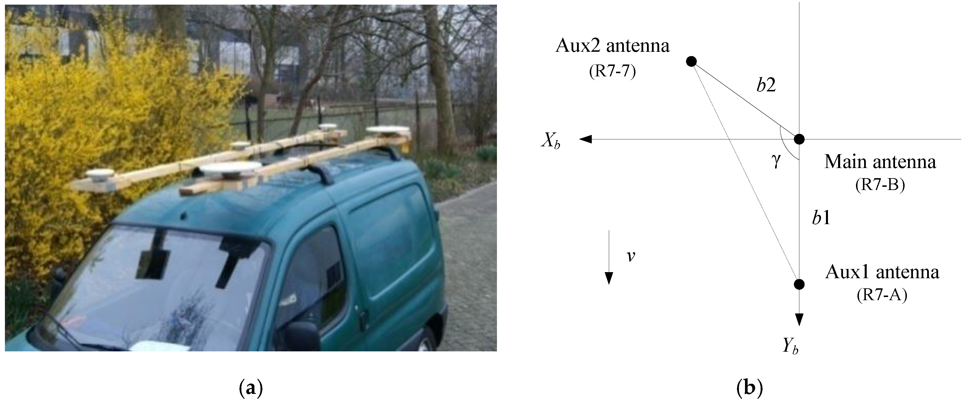
| Kinematic | b1 (0, 2.20, 0) b2 (0.69, −0.29, 0) | 2.20 0.75 | 2 |
| AD Method | STD (×10−2(°)) | SEP 95 (°) | Pfa (%) | Pmd (%) | nfix (90%) | Pc (%) | ||
|---|---|---|---|---|---|---|---|---|
| Pitch | Roll | Yaw | ||||||
| FAR-PAD | 2.93 | 6.34 | 1.22 | 0.1373 | 3.61 | 0.07 | 20 | 95.03 |
| FAR-MAD | 3.75 | 3.38 | 1.58 | 0.1010 | 19.86 | 0 | 60 | 80.00 |
| PAR-MAD | 4.23 | 3.84 | 1.78 | 0.1092 | 1.28 | 0 | 56 | 98.65 |
| AD Method | STD (°) | SEP 95 (°) | Pfa (%) | Pmd (%) | Pc (%) | ||
|---|---|---|---|---|---|---|---|
| Pitch | Roll | Yaw | |||||
| FAR-PAD | 0.1850 | 0.6423 | 0.0471 | 1.6946 | 4.10 | 0 | 95.53 |
| FAR-MAD | 0.1887 | 0.6673 | 0.0579 | 1.7435 | 15.28 | 0 | 85.30 |
| PAR-MAD | 0.2049 | 0.6802 | 0.0611 | 1.8125 | 0.07 | 0 | 96.65 |
© 2017 by the authors. Licensee MDPI, Basel, Switzerland. This article is an open access article distributed under the terms and conditions of the Creative Commons Attribution (CC BY) license ( http://creativecommons.org/licenses/by/4.0/).
Share and Cite
Zhao, L.; Li, N.; Li, L.; Zhang, Y.; Cheng, C. Real-Time GNSS-Based Attitude Determination in the Measurement Domain. Sensors 2017, 17, 296. https://doi.org/10.3390/s17020296
Zhao L, Li N, Li L, Zhang Y, Cheng C. Real-Time GNSS-Based Attitude Determination in the Measurement Domain. Sensors. 2017; 17(2):296. https://doi.org/10.3390/s17020296
Chicago/Turabian StyleZhao, Lin, Na Li, Liang Li, Yi Zhang, and Chun Cheng. 2017. "Real-Time GNSS-Based Attitude Determination in the Measurement Domain" Sensors 17, no. 2: 296. https://doi.org/10.3390/s17020296