Article

Impedance-Based Pre-Stress Monitoring of Rock Bolts Using a Piezoceramic-Based Smart Washer—A Feasibility Study

1
Key Laboratory of Transportation Tunnel Engineering, Ministry of Education, Southwest Jiaotong University, Chengdu 610031, China;
2
State Key Laboratory of Coastal and Offshore Engineering, Dalian University of Technology, Dalian 116024, China;
3
Smart Material and Structure Laboratory, Department of Mechanical Engineering, University of Houston, Houston, TX 77204, USA;
*
Author to whom correspondence should be addressed.
Sensors 2017, 17(2), 250; https://doi.org/10.3390/s17020250
Submission received: 6 January 2017 / Accepted: 24 January 2017 / Published: 27 January 2017
(This article belongs to the Section Physical Sensors)

Abstract

:
Pre-stress degradation or looseness of rock bolts in mining or tunnel engineering threatens the stability and reliability of the structures. In this paper, an innovative piezoelectric device named a “smart washer” with the impedance method is proposed with the aim of developing a real-time device to monitor the pre-stress level of rock bolts. The proposed method was verified through tests on a rock bolt specimen. By applying high-frequency sweep excitations (typically >30 kHz) to the smart washer that was installed on the rock bolt specimen, we observed that the variation in impedance signatures indicated the rock bolt pre-stress status. With the degradation of rock bolt pre-stress, the frequency in the dominating peak of the real part of the electrical impedance signature increased. To quantify the effectiveness of the proposed technique, a normalized root mean square deviation (RMSD) index was developed to evaluate the degradation level of the rock bolt pre-stress. The experimental results demonstrated that the normalized RMSD-based looseness index, which was computed from the impedance value detected by the “smart washer”, increased with loss of the pre-stress of the rock bolt. Therefore, the proposed method can effectively detect the degradation of rock bolt pre-stress, as demonstrated by experiments.

1. Introduction

Thanks to their low cost, simplicity, and ease of installation, rock bolts, as a major measure to enhance the bearing capacity of surrounding rock and foundations, have been widely used in mining, tunnel, and geotechnical engineering [1]. Rock bolts are used as either temporary or permanent support systems to prevent the movement and expansion of rock strata. Rock bolts increase the stability of surrounding rock or soil by increase the cohesiveness and internal friction angle. However, for rock-bolted structures, in some cases, pre-tension degradation may lead to a compromised structure integrity or a reduction in load bearing capacity. Therefore, monitoring the pre-load status of rock bolts is essential in evaluating the health condition of a given rock bolt and its entire structure.
A considerable amount of research has been conducted to monitor rock bolt pre-tension status. All related research can be classified into two categories: the destructive testing method and the non-destructive testing method. A destructive testing method is a traditional way of diagnosing the working condition of a rock bolt and includes core drilling detection and the pull-out test method [2]. Core drilling detection is an outdated method that is rarely used now. The pull-out test is a method that can measure the bearing state of a specific rock bolt. The shortcoming of a destructive testing method is that the rock bolt will be destroyed. The guided wave propagation in a free bar was first studied numerically in the late nineteenth century by Pochhanmer [3] and Chree [4], which formed the foundation for guided wave-based damage detection methods. In recent years, due to its non-destructive nature, the ultrasonic guided wave method, as a non-destructive testing method, has gained popularity in rock bolt monitoring. A test method based on the frequency response of rock bolts was developed to determine encapsulation conditions [5]. The test determined the dominant frequency response when the rock bolt was struck with a hammer system attached to the bolt head. Beard et al. [6,7,8,9] proposed an ultrasonic pulse echo inspection technique, which was carried out from the free end of the rock bolt. The result showed that high frequency modes have low attenuation. A research group from Dalhousie University, Canada, consecutively investigated the influence of curing time [10], grouted length [11], grout strength [12], and missing grout [13] on the characteristics of ultrasonic guided waves on the grouted rock bolt. Another research group from the Republic of Korea also systematically conducted experiments and field tests on the rock bolt integrity monitoring using ultrasonic guided waves [14,15,16]. The wavelet transform was adopted to extract useful information on the grouting conditions of the rock bolt.
An electro-mechanical impedance (EMI)-based damage detection technique using lead–zirconate–titanate (PZT) patches is becoming a promising tool for detecting local damage in a wide variety of structures [17,18,19]. In this technique, a PZT patch is employed as both a sensor and an actuator. The impedance technique detects the variations of structural mechanical impedance caused by the occurrence of damage. According to the coupling theory of a PZT patch bonded on a host structure, the electrical impedance or admittance (inverse of impedance) of the PZT patches is directly related to the mechanical impedance of the host structure and will be affected by the presence of structural damage. Through monitoring the electrical impedance or admittance of the PZT patches bonded on the host structure and comparing it to a baseline measurement, the integrity of the host structure can be qualitatively determined. The small-sized PZT patches can be easily bonded on, or embedded into, a structure, even in inaccessible areas, to monitor the damage evolution of the host structure. This technique has the advantages of real-time and minimum requirements on transducers and data processing, which facilitates autonomous structural health monitoring. Research endeavors have been reported in applying the EMI technique for damage detection in a variety of structures, such as concrete strength monitoring [20,21,22], dental implant assessment [23,24], corrosion monitoring of reinforced concrete [25], lap-joint monitoring [26], and concrete-encased composite structures [27].
In this paper, we adopted and extended a newly developed technology, called a “smart washer”, which was fabricated by sandwiching a waterproof PZT patch with two pre-machined flat metal rings for bolted connection monitoring. Previous work has shown that it has great damage detection potential for bolted connections using the active sensing method. In this study, by integrating the piezoelectric impedance method with the smart washer, the pre-tension looseness of a rock bolt was monitored. To enable the experimental study, a special loading frame that can adjust the pre-tension of a rock bolt was designed and fabricated. The piezoceramic smart washer was installed between the nut and the anchor plate on the rock bolt. The smart washer functioned as an actuator and a sensor, so it generated stress waves that travel across the rock bolt and detect the stress waves that cross the specimen. The piezoelectric impedance method was employed to measure the resonance frequency change with the rock bolt pre-tension looseness, and the relationship between the extent of the pre-tension degradation of the rock bolt and the resonance frequency of the specimen was built. In addition, based on the root mean square deviation (RMSD) method, a normalized rock bolt pre-tension looseness index is proposed here to evaluate rock bolt pre-tension looseness.

2. Principles

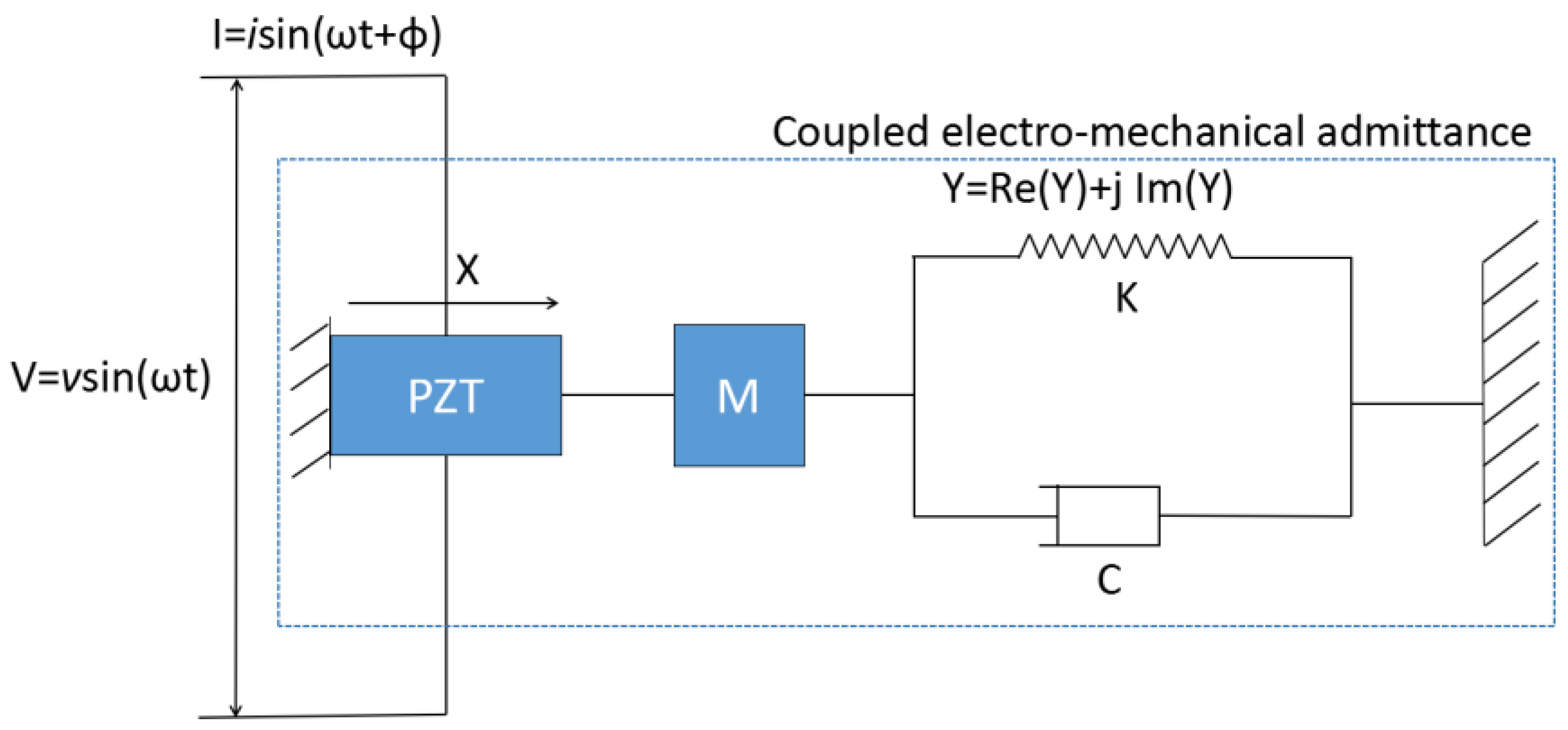
2.1. Electro-Mechanical Impedance

Electro-mechanical impedance is a novel method for monitoring local damage in a structure. The one-dimensional model of electro-mechanical impedance theory was first proposed by Liang et al. [28]. A simplified illustration of an integrated PZT and host structure system is shown in Figure 1. In this model, one end of the PZT is fixed and the system is considered a single degree-of-freedom mass-spring-damper system. Under the input of V = vsin(ωt), the impedance of the coupled system is affected by the dynamics of the PZT and the adjacent area of the host structure.
In this system, the electrical admittance Y(ω), which represents the inverse of the electrical impedance, is shown as
Y ( ω ) = j ω w l h [ Z A ( ω ) Z A ( ω ) + Z S ( ω ) d 31 2 Y ¯ 11 E tan ( κ l ) κ l + ε ¯ 33 T d 31 2 Y ¯ 11 E ]
where ZA and ZS represent the PZT’s and structure’s mechanical impedance, respectively. In addition, ω is the excitation frequency, ρ is the density of the PZT, l is the PZT length, w is the PZT width, h is the PZT thickness, κ is the wave number (= ω / c t E ), and c t E is wave velocity (= Y ¯ 11 E / ρ ). d31 is the piezoelectric constant in the x-direction at zero stress, ε ¯ 33 T = ε 33 T (1 − δ j ) and Y ¯ 11 E = Y 11 E (1 + η j), where η and δ are the mechanical loss factor and dielectric loss factor, ε 33 T is the complex dielectric constant of piezoelectric material under zero stress; Y 11 E is the complex modulus in the x-direction under zero stress. Based on this formula, the change of electrical impedance of host structure can be detected through the bonded PZT. With a high frequency excitation, very small damage can be detected.

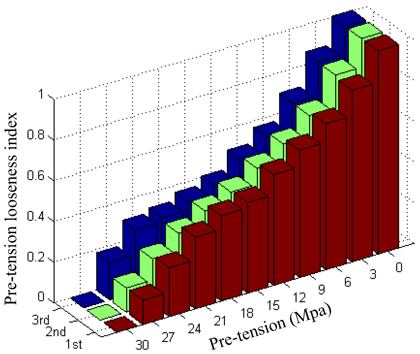
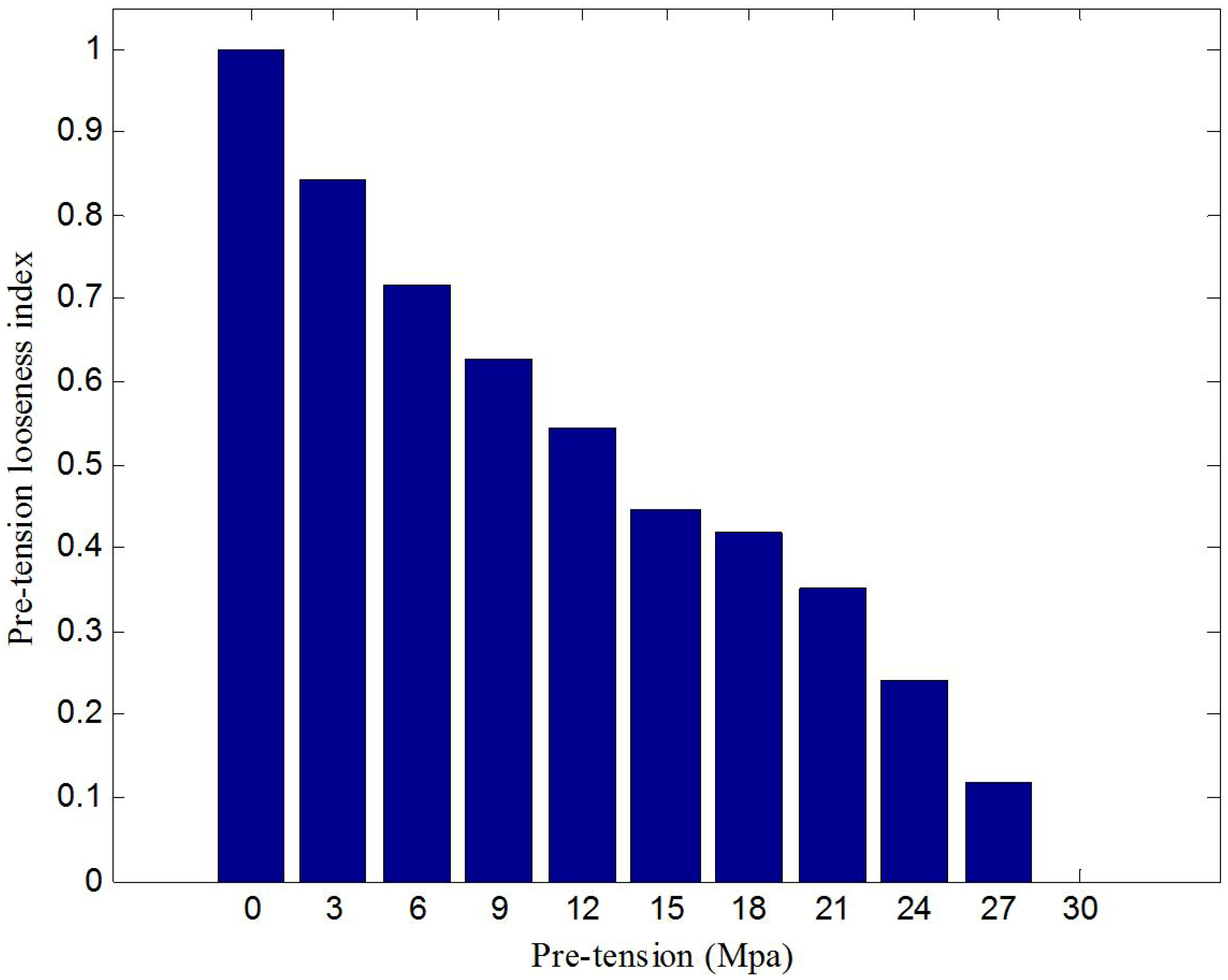
2.2. Root-Mean-Square Deviation Based Damage Index

In this study, root mean square deviation (RMSD) was applied to quantify the severity of pre-tension looseness. The RMSD method, previously used by Giurgiutiu et al. [29], has the following expression:
ρ R M S D ( % ) = i = 1 i = N ( y i x i ) 2 i = 1 i = N ( x i ) 2 × 100
where yi and xi represent the electrical impedance or electrical admittance before and after the damage, respectively. Since the electrical impedance and electrical admittance are complex, Equation (2) can be further expressed as
ρ R M S D R ( % ) = i = 1 n ( Re ( y i ) Re ( x i ) ) 2 i = 1 n ( Re ( x i ) ) 2 × 100
ρ R M S D I ( % ) = i = 1 n ( Im ( y i ) Im ( x i ) ) 2 i = 1 n ( Im ( x i ) ) 2 × 100
where ρ R M S D R and ρ R M S D I are the real part and the image part of the electrical impedance or electrical admittance before and after the damage. It should be noted that the imaginary part ε 33 T is more sensitive to the temperature variation than the real part since the dielectric constant is temperature-sensitive and only affects the imaginary part. Therefore, the real part of the admittance (or impedance) is mainly used for monitoring in applications [30].
In order to quantify the looseness degree of the pre-stress on a rock bolt, the normalization of RMSD of the real part of electrical impedance is proposed as the looseness index:
I R M S D R i = ρ R M S D R b ρ R M S D R i ρ R M S D R b ρ R M S D R t
where the i is the ith sequence number of experiment, and ρ R M S D R b and ρ R M S D R t are the RMSD values without looseness and with total looseness, respectively. In this paper, this damage index is used to evaluate rock bolt looseness or the loss of the pre-stress.

3. Experimental Tests

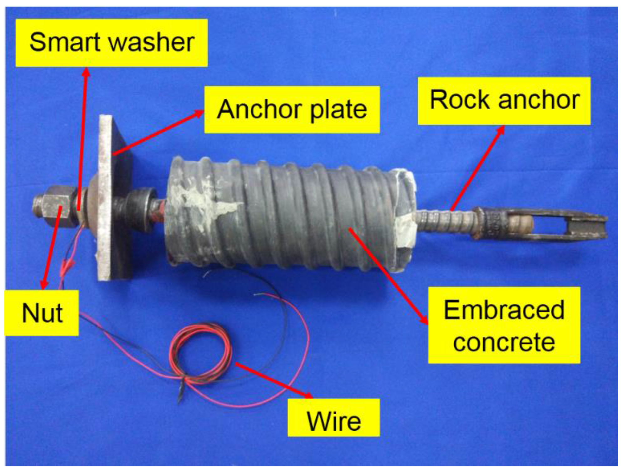
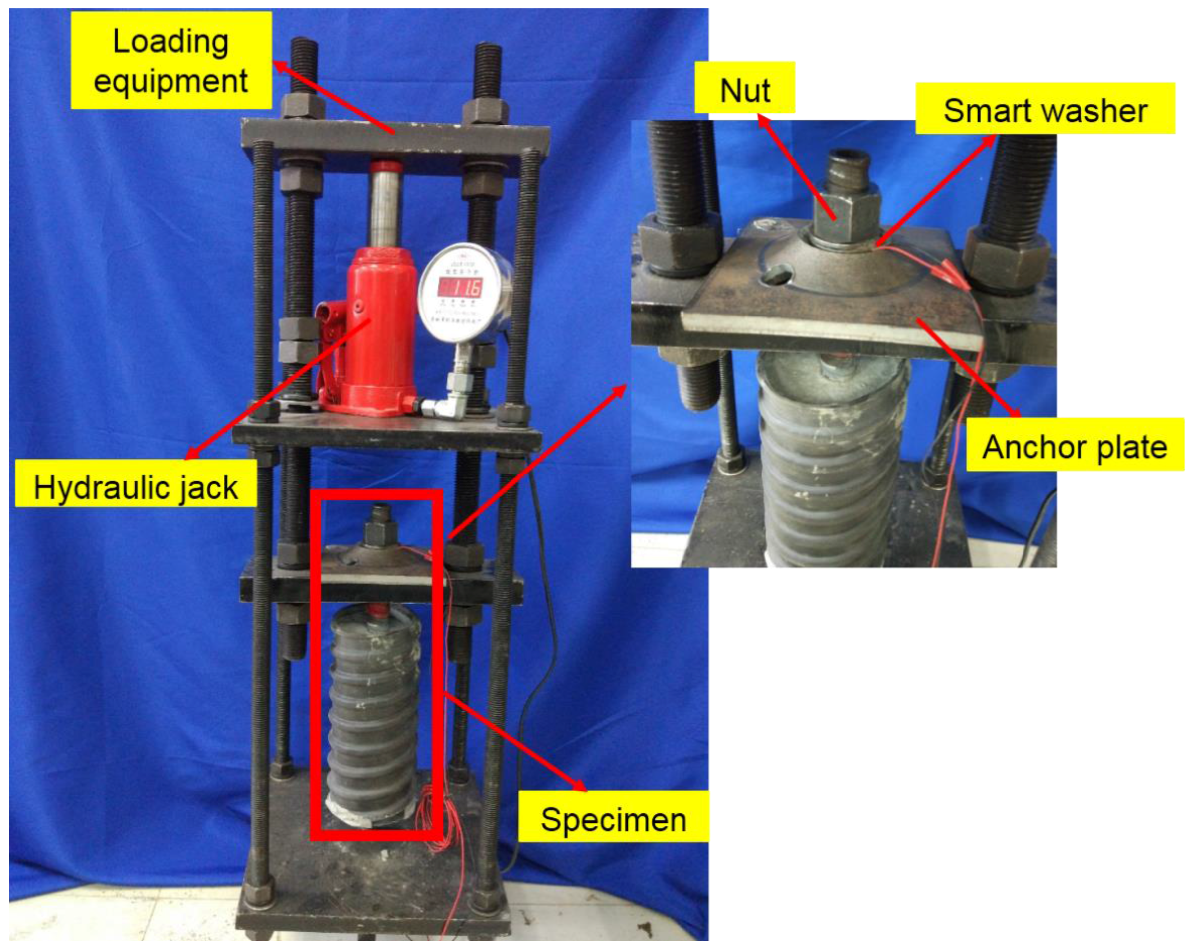
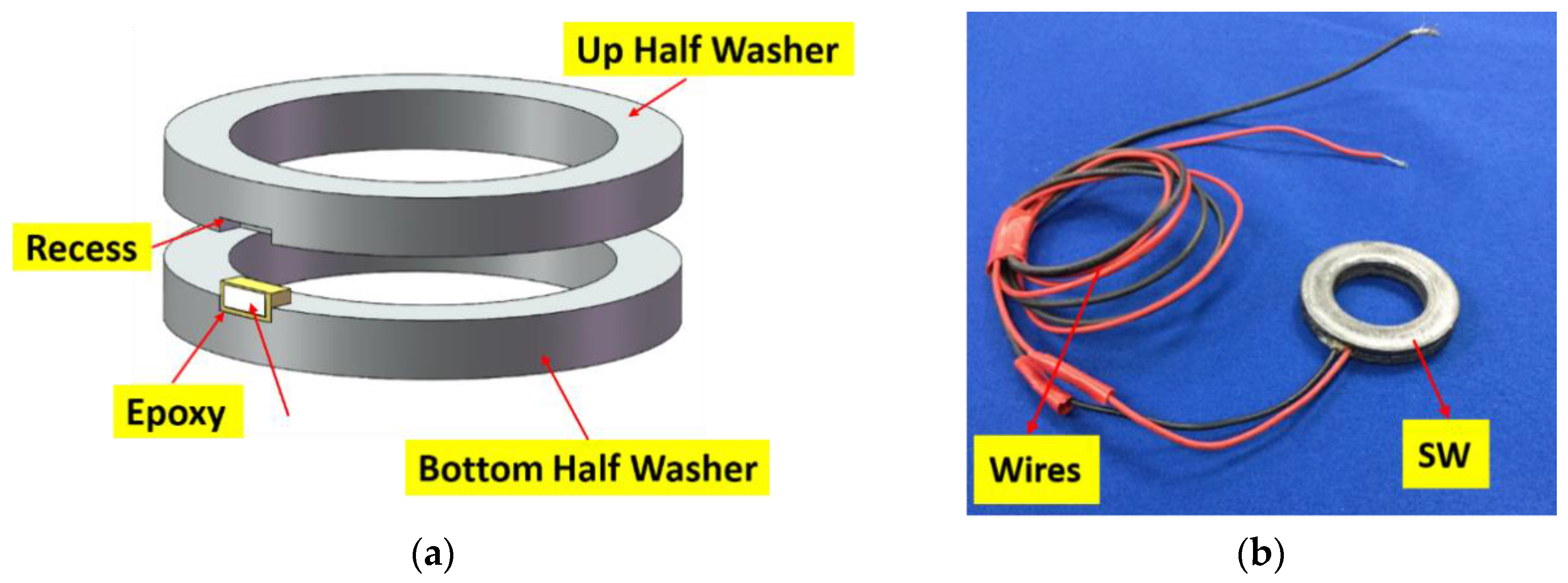
3.1. Smart Washer and Test Specimen

Piezoceramic materials, which have direct and converse piezoelectric effects, are often used to build transducers. With the direct piezoelectric effect, a piezoceramic transducer can produce an electric charge when stress is applied, and the opposite process is called the converse piezoelectric effect.
To enable easy use of piezoceramic materials in a rock bolt with proper protection, a PZT-based device, the smart washer, fabricated by sandwiching a piezoceramic transducer between two flat metal rings, as shown in Figure 2, was adopted.
In this study, the smart washer was mounted on a specimen, which consisted of a rock anchor, a heavy hex nut, a smart washer, and a bearing anchor plate. Detailed information of the specimen is shown in Figure 3.

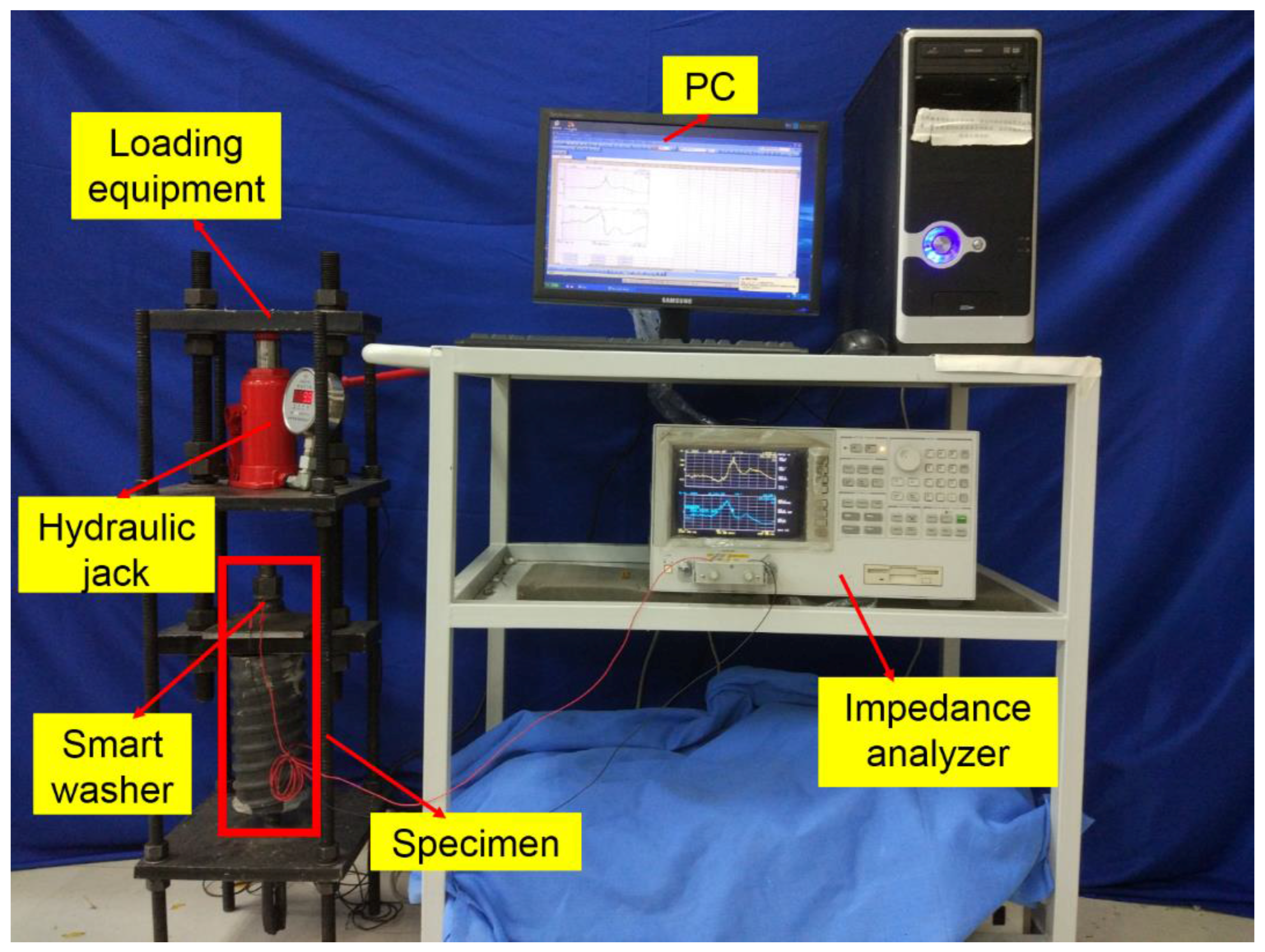
3.2. Instrumentation Setup

Smart washer-based rock bolt pre-tension monitoring using piezoelectric impedance measurement consists of three parts: a hydraulic jack, a loading frame, and an electrical impedance measuring system. The specimen fabrication is shown in Figure 4 and the experimental setup is shown in Figure 5.
In the experiment, the pre-tension or the pre-stress of rock bolt was controlled by the hydraulic jack with a range of 0–30 MPa. The loading procedure that consisted of eleven loading cases from 30 MPa to 0 MPa was carried out, as listed in Table 1. The decrease of the stress or the tension of the rock bolt simulates the process of the loss of pre-stress, the loss of pre-tension, or the looseness of the rock bolt. For example, the case of 0 MPa indicates the total looseness of the rock bolt.

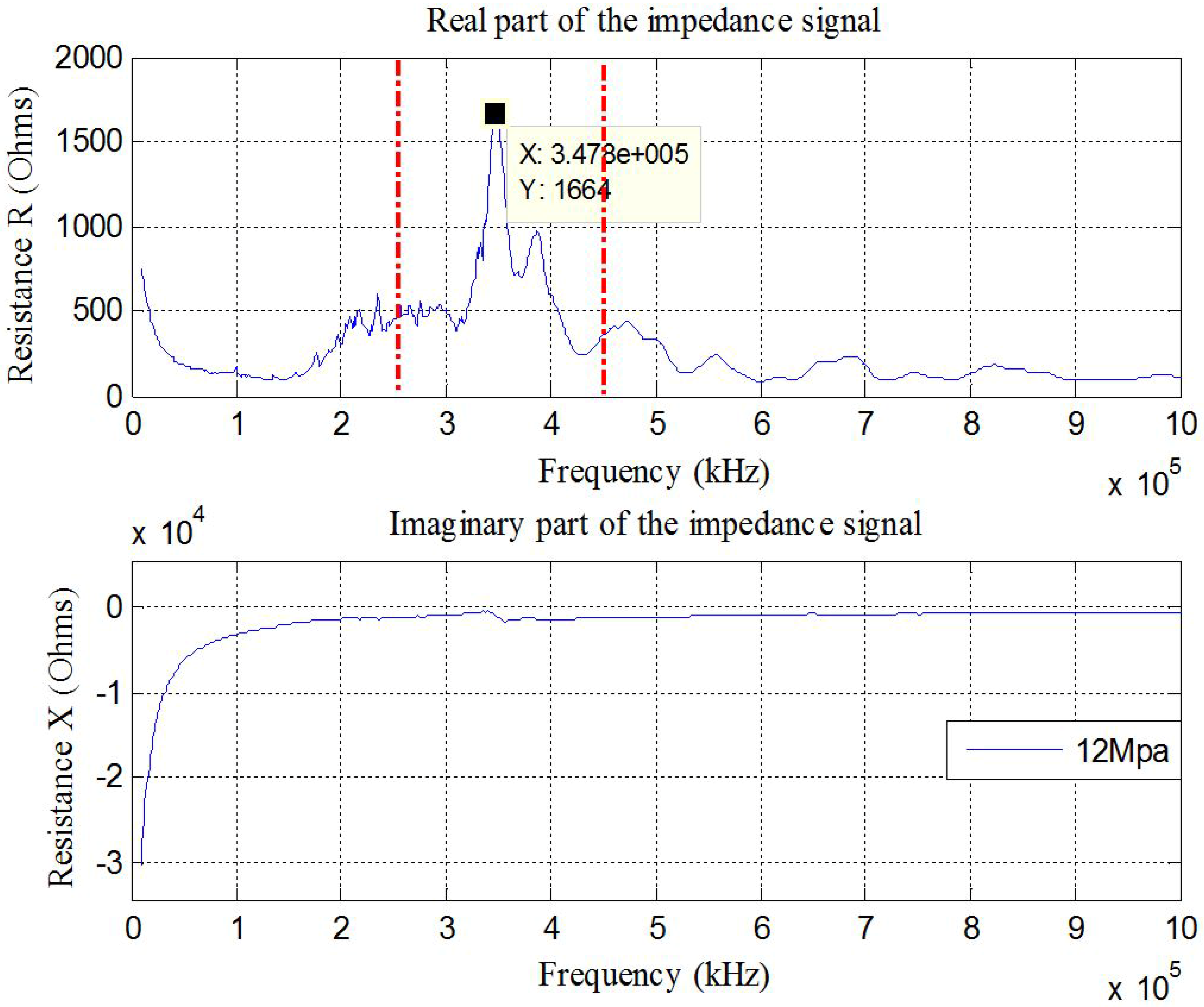
3.3. Test Procedures and Frequency Range

The smart washer impedance test procedures were carried out in two steps:
(1) The wide frequency range test: To detect the incipient-type damage, the wavelength of the excitation signal should be less than the characteristic length of the damage. With high frequency excitation when the wavelength is much smaller than that of the damage, it is easy to detect the change in structural integrity. Excitation of 10–1000 kHz with 801 sampling data points was used with a pre-stress of 12 MPa in this experiment, as shown in Figure 6.
(2) The narrow frequency range test. From Figure 6, there is a sharp peak around 347.8 kHz between the red dotted lines in the real part of the electrical impedance signature. According to the Sauerbrey equation [31], the frequency shifts in the dominating peaks of the impedance signature of the PZT patch are proportional to the square of its fundamental resonance frequency. It is expected that some changes of the mechanical properties of the host structure may have caused some significant variation in the resonance frequency shifts of the electro-mechanical impedance functions of the PZT patch. To find the change in peak frequency value, a narrow frequency range from 250 kHz to 450 kHz was used.

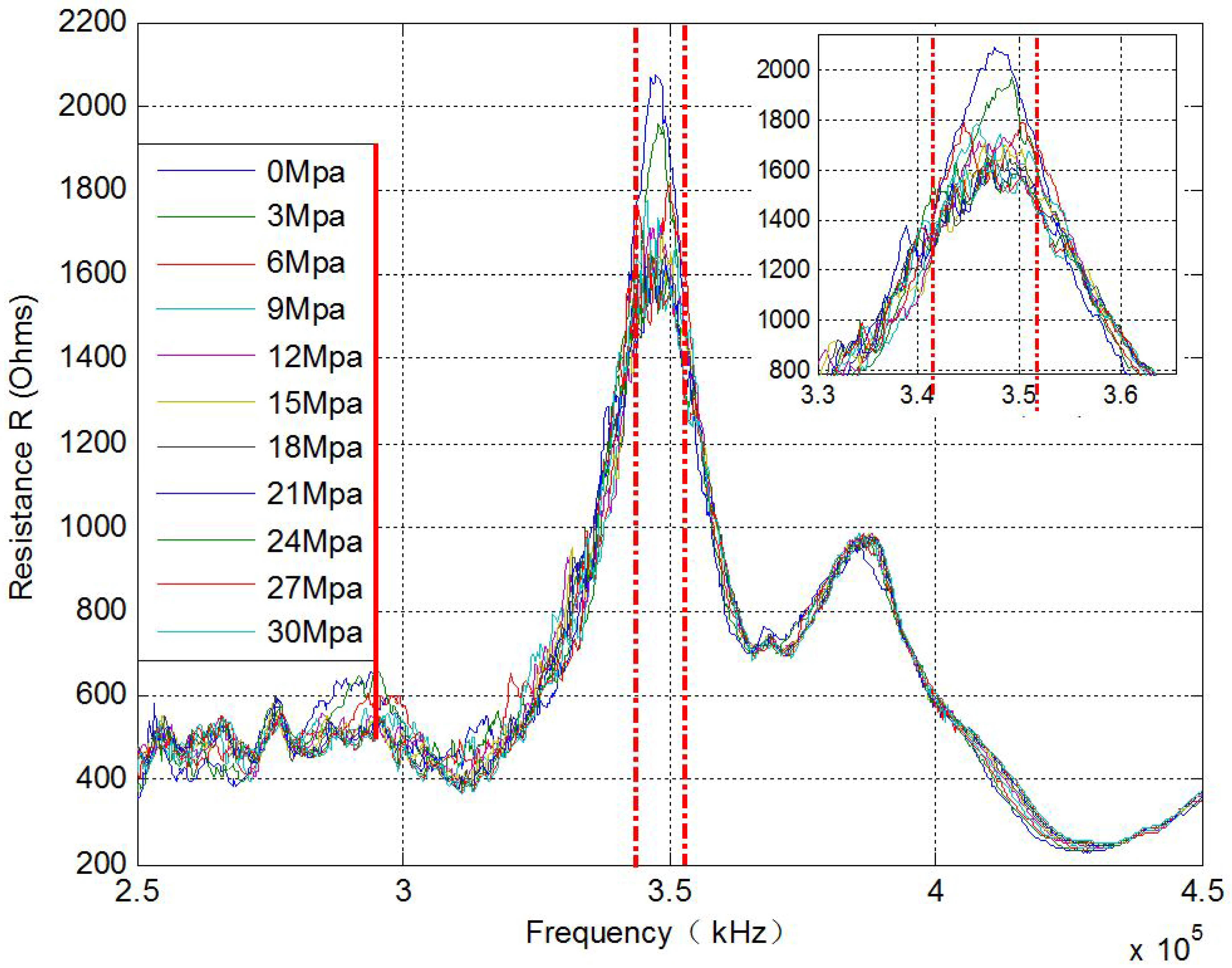
4. Experimental Results and Analysis

According to Table 1, 11 different loading scenarios were investigated with the pre-stress level reduced from 30 MPa to 0 MPa. For each loading case, the electrical impedance signature of the PZT transducer was directly acquired by the impedance analyzer. The real parts of the electrical impedance for the eleven tests over the frequency range of 250 kHz to 450 kHz are shown in Figure 7. There is a frequency shift at the peak frequency in Figure 7. However, with the development of the loss of the pre-stress, the dominating frequency peak shifts back and forth, and the dominating frequency peak cannot be used as an index to indicate pre-stress change.
To reveal the looseness quantitatively, the normalized RMSD-based rock bolt looseness index was used. With the help of Equation (5), the processed result is shown in Figure 8. The bolt looseness index is 0 in the case of 30 MPa pre-tension (without the loss of any pre-stress); in the case of a rock bolt load of 0 MPa (completely looseness), the rock bolt looseness index is 1. The indexes clearly show that bolt looseness increases with reductions in applied torque. Figure 9 shows the experimental results of three repeated experiments, which validate the reliability and repeatability of the proposed looseness index. It is clear that the rock bolt pre-tension looseness index can effectively reflect the severity of the rock bolt looseness.

5. Conclusions

In this paper, a piezoceramic smart washer is proposed to monitor the pre-load or pre-stress loss of a rock bolt. The authors propose a robust and feasible rock bolt looseness monitoring approach, which is based on the electro-mechanical impedance method. A rock bolt specimen with a smart washer was investigated under different pre-stress levels. Due to a structural stiffness reduction, the frequency of the real part of the electrical impedance signature increased with the decrease in pre-stress levels. Furthermore, a normalized RMSD bolt looseness index was applied to show the severity of rock bolt pre-stress loss, and the proposed method successfully monitored the looseness level of the rock bolt, as demonstrated experimentally. Future work will involve field testing of the proposed method, with more testing sets to assess the feasibility of the proposed smart washer and looseness index.

Acknowledgments

This work was partially supported by the Major State Basic Research Development Program of China (973 Program, grant No. 2015CB057704) and the National Natural Science Foundation of China (grant No. 51478080, No. 51278084, No. 51378434 and No. 51578456). The authors would like to express their gratitude for these financial supports.

Author Contributions

B.W. developed the concept, designed the experiments, and wrote part of the paper; L.H. designed the experiments and wrote part of the paper; D.C. conducted the experiments and analyzed the data; W.L. helped write part of the paper; G.S. developed the concept and made critical revisions to the paper.

Conflicts of Interest

The authors declare no conflict of interest.

References

  1. Qian, K.; Xin, X.-D.; Che, Y.-L. The design and application of rock bolting in coal mine. Energy Procedia 2012, 14, 280–284. [Google Scholar]
  2. Benmokrane, B.; Chennouf, A.; Mitri, H. Laboratory evaluation of cement-based grouts and grouted rock anchors. Int. J. Rock Mech. Min. Sci. Geomech. Abstr. 1995, 32, 633–642. [Google Scholar] [CrossRef]
  3. Pochhammer, L. Ueber die fortpflanzungsgeschwindigkeiten kleiner schwingungen in einem unbegrenzten isotropen kreiscylinder. J. Reine Angew. Math. 1876, 81, 324–336. [Google Scholar]
  4. Chree, C. The equations of an isotropic elastic solid in polar and cylindrical co-ordinates their solution and application. Trans. Camb. Philos. Soc. 1889, 14, 250–369. [Google Scholar]
  5. Vrkljan, I.; Szavits-Nossan, A.; Kovacevic, M. Non-destructive method for testing grouting quality of rockbolt anchors. In Proceedings of the 9th International Congress on Rock Mechanics, Paris, France, 25–28 August 1999; pp. 1475–1478.
  6. Beard, M.; Lowe, M.; Cawley, P. Inspection of rockbolts using guided ultrasonic waves. In Review of Progress in Quantitative Nondestructive Evaluation; AIP Publishing: Melville, NY, USA, 2001; Volume 20, pp. 1156–1163. [Google Scholar]
  7. Beard, M.D. Guided wave Inspection of Embedded Cylindrical Structures. Ph.D. Thesis, Department of Mechanical Engineering, Imperial College, London, UK, 2002. [Google Scholar]
  8. Beard, M.; Lowe, M. Non-destructive testing of rock bolts using guided ultrasonic waves. Int. J. Rock Mech. Min. Sci. 2003, 40, 527–536. [Google Scholar] [CrossRef]
  9. Beard, M.; Lowe, M.; Cawley, P. Ultrasonic guided waves for inspection of grouted tendons and bolts. J. Mater. Civ. Eng. 2003, 15, 212–218. [Google Scholar] [CrossRef]
  10. Madenga, V.; Zou, D.; Zhang, C. Effects of curing time and frequency on ultrasonic wave velocity in grouted rock bolts. J. Appl. Geophys. 2006, 59, 79–87. [Google Scholar] [CrossRef]
  11. Zou, D.; Cui, Y.; Madenga, V.; Zhang, C. Effects of frequency and grouted length on the behavior of guided ultrasonic waves in rock bolts. Int. J. Rock Mech. Min. Sci. 2007, 44, 813–819. [Google Scholar] [CrossRef]
  12. Zou, D.S.; Cheng, J.; Yue, R.; Sun, X. Grout quality and its impact on guided ultrasonic waves in grouted rock bolts. J. Appl. Geophys. 2010, 72, 102–106. [Google Scholar] [CrossRef]
  13. Cui, Y.; Zou, D. Assessing the effects of insufficient rebar and missing grout in grouted rock bolts using guided ultrasonic waves. J. Appl. Geophys. 2012, 79, 64–70. [Google Scholar] [CrossRef]
  14. Han, S.-I.; Lee, I.-M.; Lee, Y.-J.; Lee, J.-S. Evaluation of rock bolt integrity using guided ultrasonic waves. Geotech. Test. J. 2009, 32, 31–38. [Google Scholar]
  15. Lee, I.-M.; Han, S.-I.; Kim, H.-J.; Yu, J.-D.; Min, B.-K.; Lee, J.-S. Evaluation of rock bolt integrity using fourier and wavelet transforms. Tunn. Undergr. Space Technol. 2012, 28, 304–314. [Google Scholar] [CrossRef]
  16. Yu, J.-D.; Bae, M.-H.; Lee, I.-M.; Lee, J.-S. Nongrouted ratio evaluation of rock bolts by reflection of guided ultrasonic waves. J. Geotech. Geoenviron. Eng. 2012, 139, 298–307. [Google Scholar] [CrossRef]
  17. Boukabache, H.; Escriba, C.; Zedek, S.; Medale, D.; Rolet, S.; Fourniols, J.Y. System-on-chip integration of a new electromechanical impedance calculation method for aircraft structure health monitoring. Sensors 2012, 12, 13617–13635. [Google Scholar] [CrossRef] [PubMed]
  18. Hu, X.; Zhu, H.; Wang, D. A study of concrete slab damage detection based on the electromechanical impedance method. Sensors 2014, 14, 19897–19909. [Google Scholar] [CrossRef] [PubMed]
  19. Wang, D.; Wang, Q.; Wang, H.; Zhu, H. Experimental study on damage detection in timber specimens based on an electromechanical impedance technique and RMSD-based mahalanobis distance. Sensors 2016, 16, 1765. [Google Scholar] [CrossRef] [PubMed]
  20. Shin, S.W.; Oh, T.K. Application of electro-mechanical impedance sensing technique for online monitoring of strength development in concrete using smart PZT patches. Constr. Build. Mater. 2009, 23, 1185–1188. [Google Scholar] [CrossRef]
  21. Tawie, R.; Lee, H. Monitoring the strength development in concrete by emi sensing technique. Constr. Build. Mater. 2010, 24, 1746–1753. [Google Scholar] [CrossRef]
  22. Wang, D.; Zhu, H. Monitoring of the strength gain of concrete using embedded PZT impedance transducer. Constr. Build. Mater. 2011, 25, 3703–3708. [Google Scholar] [CrossRef]
  23. Boemio, G.; Rizzo, P.; De Nardo, L. Assessment of dental implant stability by means of the electromechanical impedance method. Smart Mater. Struct. 2011, 20, 045008. [Google Scholar] [CrossRef]
  24. Tabrizi, A.; Rizzo, P.; Ochs, M.W. Electromechanical impedance method to assess dental implant stability. Smart Mater. Struct. 2012, 21, 115022. [Google Scholar] [CrossRef]
  25. Talakokula, V.; Bhalla, S.; Gupta, A. Corrosion assessment of reinforced concrete structures based on equivalent structural parameters using electro-mechanical impedance technique. J. Intell. Mater. Syst. Struct. 2013. [Google Scholar] [CrossRef]
  26. Dugnani, R.; Zhuang, Y.; Kopsaftopoulos, F.; Chang, F.-K. Adhesive bond-line degradation detection via a cross-correlation electromechanical impedance–based approach. Struct. Health Monit. 2016, 15, 650–667. [Google Scholar] [CrossRef]
  27. Liang, Y.; Li, D.; Parvasi, S.M.; Kong, Q.; Song, G. Bond-slip detection of concrete-encased composite structure using electro-mechanical impedance technique. Smart Mater. Struct. 2016, 25, 095003. [Google Scholar] [CrossRef]
  28. Liang, C.; Sun, F.; Rogers, C. Coupled electro-mechanical analysis of adaptive material systems—Determination of the actuator power consumption and system energy transfer. J. Intell. Mater. Syst. Struct. 1994, 5, 12–20. [Google Scholar] [CrossRef]
  29. Giurgiutiu, V.; Rogers, C.A. Recent advancements in the electromechanical (E/M) impedance method for structural health monitoring and NDE. In Proceedings of the 5th Annual International Symposium on Smart Structures and Materials, San Diego, CA, USA, 1–5 March 1998; pp. 536–547.
  30. Park, G.; Sohn, H.; Farrar, C.R.; Inman, D.J. Overview of piezoelectric impedance-based health monitoring and path forward. Shock Vib. Dig. 2003, 35, 451–463. [Google Scholar] [CrossRef]
  31. Sauerbrey, G. Verwendung von schwingquarzen zur wägung dünner schichten und zur mikrowägung. Zeitschrift für Physik 1959, 155, 206–222. (In German) [Google Scholar] [CrossRef]
Figure 1. 1-D model for the lead–zirconate–titanate (PZT)-drive dynamic structural system.
Sensors 17 00250 g001
Figure 2. The design of the smart washer with connecting wires: (a) schematic diagram and (b) photograph.
Sensors 17 00250 g002
Figure 3. Detailed information of the rock bolt specimen.
Sensors 17 00250 g003
Figure 4. The loading system of rock bolt specimen.
Sensors 17 00250 g004
Figure 5. The entire experimental setup.
Sensors 17 00250 g005
Figure 6. Electrical impedance signature acquired from the PZT patch (10 kHz–1 MHz).
Sensors 17 00250 g006
Figure 7. Electrical impedance signature of real part acquired from the SW (250 kHz–450 kHz).
Sensors 17 00250 g007
Figure 8. Normalized RMSD-based rock bolt looseness index from the first experiment.
Sensors 17 00250 g008
Figure 9. The normalized RMSD-based rock bolt looseness indices of three repeated experiments.
Sensors 17 00250 g009
Table 1. Experimental procedure with eleven loading cases.
Sequence Number1234567891011
Pre-load (MPa)302724211815129630

