Micro and Nanostructured Materials for the Development of Optical Fibre Sensors

 , ,
, ,  , ,
, ,  and
and 
Abstract
:1. Introduction
2. Fundamentals of Optical Fibre Sensors
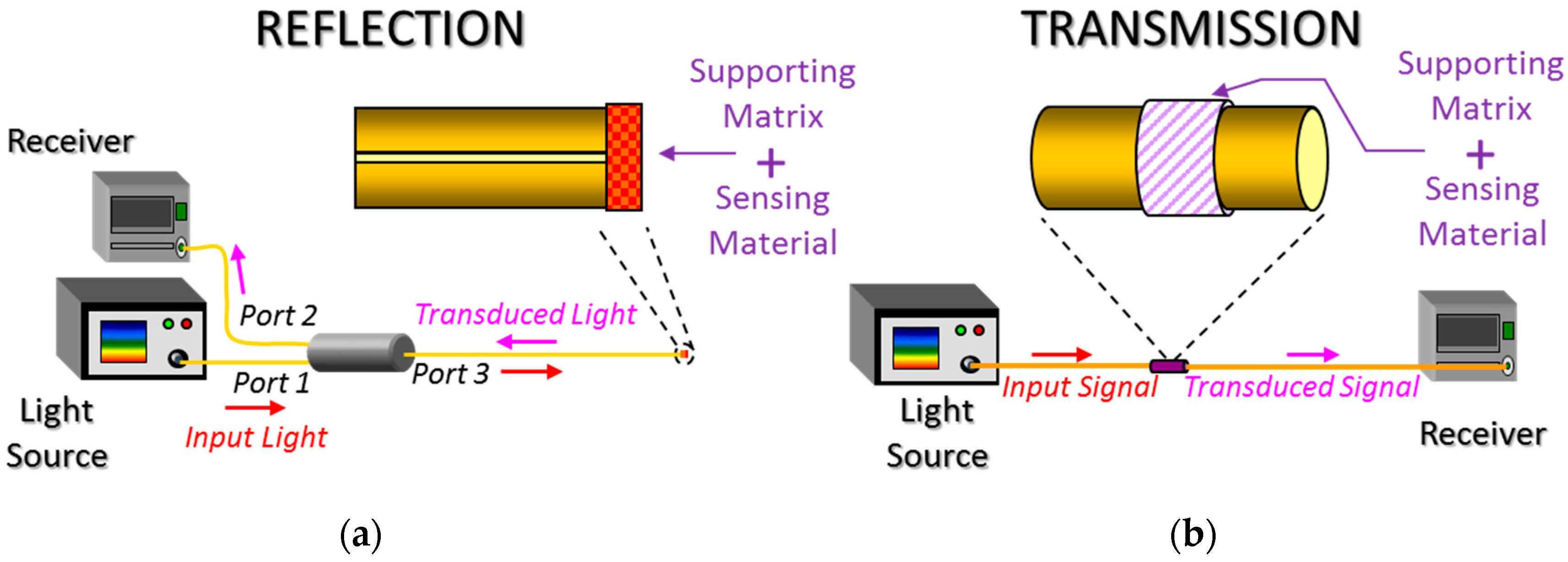
2.1. Theoretical Background and Main Architectures
2.2. Optical Absorption
2.3. Luminescence
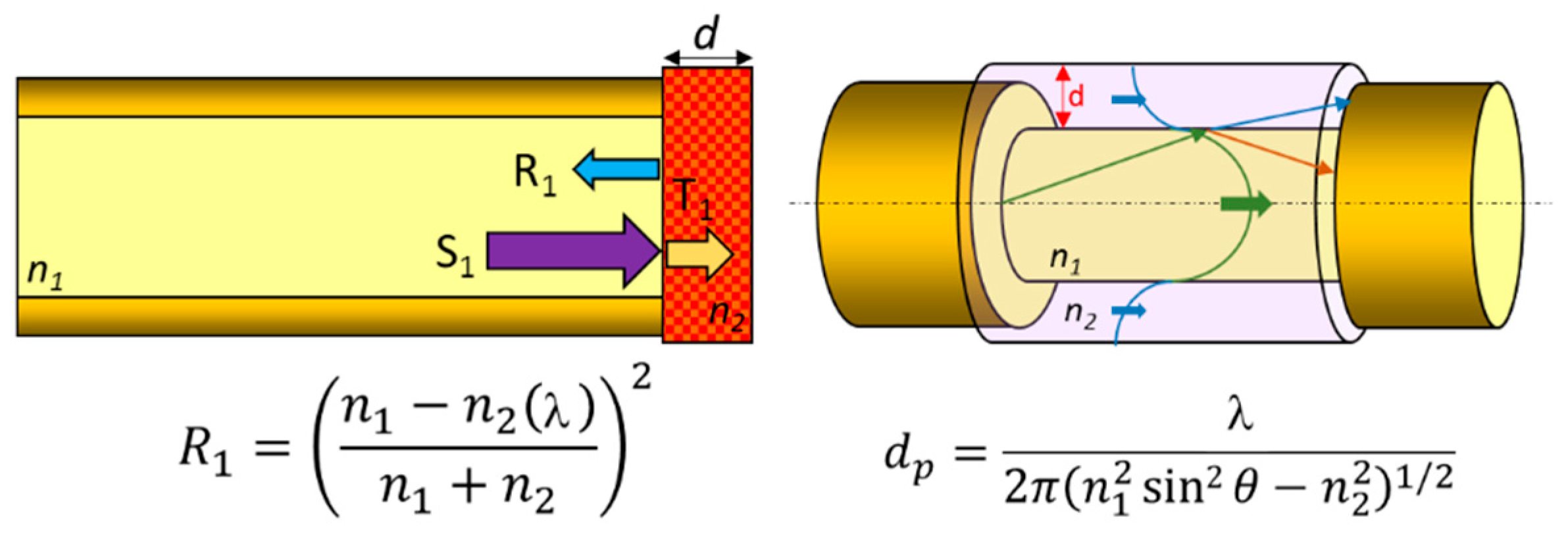
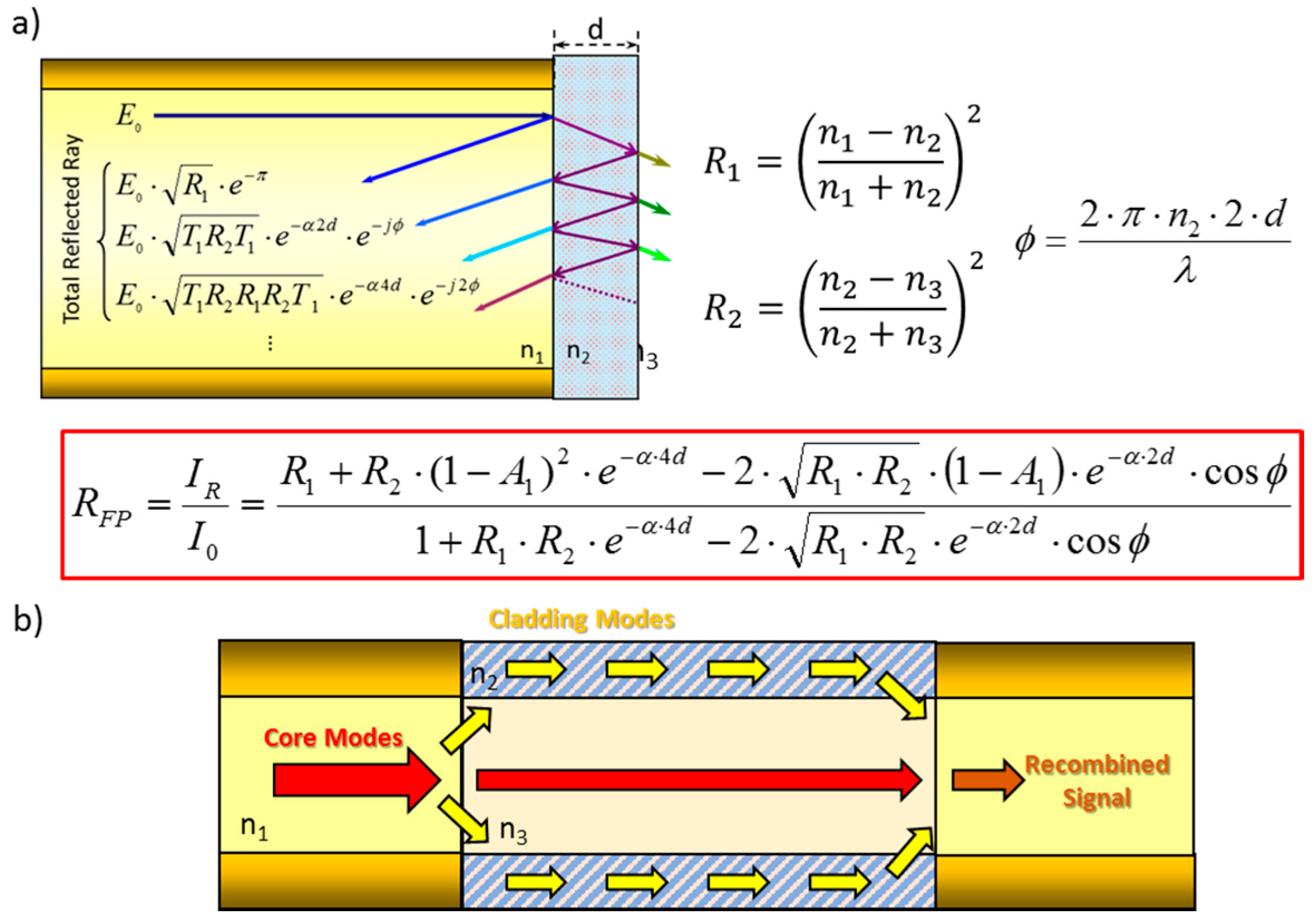
2.4. Interferometry
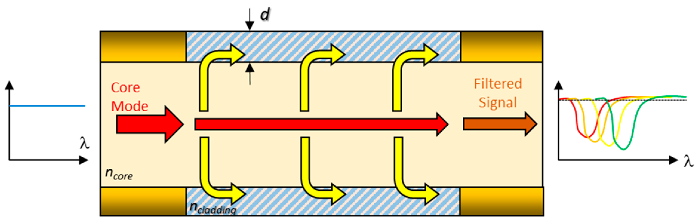
2.5. Electromagnetic Resonances
3. Techniques for the Development of Sensors
3.1. Dip Coating
3.2. Layer-By-Layer Nano Assembly (LbL)
3.3. Sputtering
3.4. Electrospun Nano Webs
4. Nano and Microstructured Materials for Sensing
4.1. Microstructured Optical Fibres
4.2. Nanostructures
4.3. Plastic Matrices
4.4. Sol Gel
4.5. Metal Oxides
4.6. Carbon Nano Tubes (CNTs)
4.7. Nanowires
4.8. Molecularly Imprinted Polymers (MIPs)
4.9. Layer-By-Layer (LbL) Nanostructures
4.10. Electrospun Nano-Fibres
5. Conclusions
Acknowledgments
Conflicts of Interest
References
- Gaab, M.R. Instrumentation: Endoscopes and equipment. World Neurosurg. 2013, 79. [Google Scholar] [CrossRef] [PubMed]
- Barrias, A.; Casas, J.R.; Villalba, S. A review of distributed optical fiber sensors for civil engineering applications. Sensors 2016, 16, 748. [Google Scholar] [CrossRef] [PubMed] [Green Version]
- Pospíšilová, M.; Kuncová, G.; Trögl, J. Fiber-optic chemical sensors and fiber-optic bio-sensors. Sensors 2015, 15. [Google Scholar] [CrossRef] [PubMed]
- Lin, J. Recent development and applications of optical and fiber-optic pH sensors. TrAC Trends Anal. Chem. 2000, 19. [Google Scholar] [CrossRef]
- Elosua, C.; Matias, I.R.; Bariain, C.; Arregui, F.J. Volatile organic compound optical fiber sensors: A review. Sensors 2006, 6, 1440–1465. [Google Scholar] [CrossRef]
- Kolpakov, S.A.; Gordon, N.T.; Mou, C.; Zhou, K. Toward a new generation of photonic humidity sensors. Sensors 2014, 14, 3986–4013. [Google Scholar] [CrossRef] [PubMed]
- Miao, Y.-P.; Jin, W.; Yang, F.; Lin, Y.-C.; Tan, Y.-Z.; Hoi, L.H. Advances in optical fiber photothermal interferometry for gas detection. Wuli Xuebao/Acta Phys. Sin. 2017, 66. [Google Scholar] [CrossRef]
- Fang, Z.; Chin, K.K.; Qu, R.; Cai, H. Fundamentals of Optical Fiber Sensors; Wiley: Hoboken, NJ, USA, 2012; ISBN 9780470575406. [Google Scholar]
- Koike, Y.; Koike, K. Progress in low-loss and high-bandwidth plastic optical fibers. J. Polym. Sci. Part B Polym. Phys. 2011, 49. [Google Scholar] [CrossRef]
- Liehr, S. Polymer Optical Fiber Sensors in Structural Health Monitoring; Springer: New York, NY, USA, 2011; Volume 96, ISBN 9783642210983. [Google Scholar]
- Bilro, L.; Alberto, N.; Pinto, J.L.; Nogueira, R. Optical sensors based on plastic fibers. Sensors 2012, 12. [Google Scholar] [CrossRef] [PubMed]
- Leung, A.; Mohana Shankar, P.; Mutharasan, R. Evanescent Field Tapered Fiber Optic Biosensors (TFOBS): Fabrication, Antibody Immobilization and Detection; Nova: New York NY, USA, 2012; ISBN 9781613245057. [Google Scholar]
- André, R.M.; Marques, M.B.; Frazão, O. New Advances in Tapered Fiber Sensors; Nova: New York NY, USA, 2013; ISBN 9781628084283. [Google Scholar]
- Punjabi, N.; Satija, J.; Mukherji, S. Evanescent Wave Absorption Based Fiber-Optic Sensor—Cascading of Bend and Tapered Geometry for Enhanced Sensitivity; Springer: New York, NY, USA, 2015; Volume 11. [Google Scholar]
- Spillman, W.B. Multimode Polarization Sensors; Wiley: Hoboken, NJ, USA, 2011; ISBN 9780470126844. [Google Scholar]
- Lee, B.H.; Kim, Y.H.; Park, K.S.; Eom, J.B.; Kim, M.J.; Rho, B.S.; Choi, H.Y. Interferometric fiber optic sensors. Sensors 2012, 12, 2467–2486. [Google Scholar] [CrossRef] [PubMed]
- Hill, K.O.; Meltz, G. Fiber Bragg grating technology fundamentals and overview. J. Lightwave Technol. 1997, 15. [Google Scholar] [CrossRef]
- James, S.W.; Tatam, R.P. Optical fibre long-period grating sensors: Characteristics and application. Meas. Sci. Technol. 2003, 14. [Google Scholar] [CrossRef]
- Shevchenko, Y.Y.; Blair, D.A.D.; Derosa, M.C.; Albert, J. DNA target detection using gold-coated tilted fiber Bragg gratings in aqueous media. In Proceedings of the 2008 Conference on Quantum Electronics and Laser Science Conference on Lasers and Electro-Optics, CLEO/QELS, San Jose, CA, USA, 4–9 May 2008. [Google Scholar]
- Candiani, A.; Sozzi, M.; Cucinotta, A.; Selleri, S.; Veneziano, R.; Corradini, R.; Marchelli, R.; Childs, P.; Pissadakis, S. Optical fiber ring cavity sensor for label-free DNA detection. IEEE J. Sel. Top. Quantum Electron. 2012, 18. [Google Scholar] [CrossRef]
- Gupta, B.D.; Verma, R.K. Surface plasmon resonance-based fiber optic sensors: Principle, probe designs, and some applications. J. Sensors 2009, 2009. [Google Scholar] [CrossRef]
- Del Villar, I.; Arregui, F.J.; Zamarreño, C.R.; Corres, J.M.; Bariain, C.; Goicoechea, J.; Elosua, C.; Hernaez, M.; Rivero, P.J.; Socorro, A.B.; et al. Optical sensors based on lossy-mode resonances. Sens. Actuators B Chem. 2017, 240. [Google Scholar] [CrossRef]
- Pilevar, S.; DeLisa, M.P.; Zhang, Z.; Davis, C.C.; Bentley, W.E.; Sirkis, J.S. Evanescent wave antibody-antigen biosensor based on long period fiber Bragg grating. In Proceedings of SPIE—The International Society for Optical Engineering; Society of Photo-Optical Instrumentation Engineers: Bellingham, WA, USA, 2000; Volume 4185. [Google Scholar]
- Chen, X.; Zhang, L.; Zhou, K.; Davies, E.; Sugden, K.; Bennion, I.; Hughes, M.; Hine, A. Real-time detection of DNA interactions with longperiod fiber-grating-based biosensor. Opt. Lett. 2007, 32. [Google Scholar] [CrossRef]
- He, Z.; Tian, F.; Zhu, Y.; Lavlinskaia, N.; Du, H. Long-period gratings in photonic crystal fiber as an optofluidic label-free biosensor. Biosens. Bioelectron. 2011, 26. [Google Scholar] [CrossRef] [PubMed]
- Maguis, S.; Laffont, G.; Ferdinand, P.; Carbonnier, B.; Kham, K.; Mekhalif, T.; Millot, M.-C. Biofunctionalized tilted Fiber Bragg Gratings for label-free immunosensing. Opt. Express 2008, 16. [Google Scholar] [CrossRef]
- González-Sierra, N.; Gómez-Pavón, L.; Pérez-Sánchez, G.; Luis-Ramos, A.; Zaca-Morán, P.; Muñoz-Pacheco, J.; Chávez-Ramírez, F. Tapered Optical Fiber Functionalized with Palladium Nanoparticles by Drop Casting and Laser Radiation for H2 and Volatile Organic Compounds Sensing Purposes. Sensors 2017, 17, 2039. [Google Scholar] [CrossRef] [PubMed]
- Shabaneh, A.A.; Girei, S.H.; Arasu, P.T.; Rashid, S.A.; Yunusa, Z.; Mahdi, M.A.; Paiman, S.; Ahmad, M.Z.; Yaacob, M.H. Reflectance Response of Optical Fiber Coated With Carbon Nanotubes for Aqueous Ethanol Sensing. IEEE Photonics J. 2014, 6. [Google Scholar] [CrossRef]
- Iler, R.K. Multilayers of colloidal particles. J. Colloid Interface Sci. 1966, 21, 569–594. [Google Scholar] [CrossRef]
- Decher, G. Fuzzy nanoassemblies: Toward layered polymeric multicomposites. Science 1997, 277. [Google Scholar] [CrossRef]
- Elosua, C.; Lopez-Torres, D.; Hernaez, M.; Matias, I.R.; Arregui, F.J. Comparative study of layer-by-layer deposition techniques for poly(sodium phosphate) and poly(allylamine hydrochloride). Nanoscale Res. Lett. 2013, 8. [Google Scholar] [CrossRef] [PubMed]
- Teo, W.E.; Ramakrishna, S. A review on electrospinning design and nanofibre assemblies. Nanotechnology 2006, 17, R89–R106. [Google Scholar] [CrossRef] [PubMed]
- Wang, X.; Drew, C.; Lee, S.H.; Senecal, K.J.; Kumar, J.; Samuelson, L.A. Electrospun Nanofibrous Membranes for Highly Sensitive Optical Sensors. Nano Lett. 2002, 2, 1273–1275. [Google Scholar] [CrossRef]
- Song, X.; Wang, Z.; Liu, Y.; Wang, C.; Li, L. A highly sensitive ethanol sensor based on mesoporous ZnO-SnO2 nanofibers. Nanotechnology 2009, 20, 75501. [Google Scholar] [CrossRef] [PubMed]
- Son, D.; Kim, S.J.; Lee, S. Electrospun assembly : A nondestructive nanofabrication for transparent photosensors. Nanotechnology 2017, 28, 155202. [Google Scholar] [CrossRef]
- Wolf, C.; Tscherner, M.; Kstler, S. Ultra-fast opto-chemical sensors by using electrospun nanofibers as sensing layers. Sens. Actuators B Chem. 2015, 209, 1064–1069. [Google Scholar] [CrossRef]
- Urrutia, A.; Goicoechea, J.; Rivero, P.J.; Matías, I.R.; Arregui, F.J. Electrospun nanofiber mats for evanescent optical fiber sensors. Sens. Actuators B Chem. 2013, 176, 569–576. [Google Scholar] [CrossRef]
- Tseng, Y.-T.; Chuang, Y.-J.; Wu, Y.-C.; Yang, C.-S.; Wang, M.-C.; Tseng, F.-G. A gold-nanoparticle-enhanced immune sensor based on fiber optic interferometry. Nanotechnology 2008, 19. [Google Scholar] [CrossRef] [PubMed]
- Saikia, R.; Buragohain, M.; Datta, P.; Nath, P.; Barua, K. Fiber-optic pH sensor based on SPR of silver nanostructured film. AIP Conf. Proc. 2009, 1147, 249–255. [Google Scholar]
- Mahros, A.M.; Tharwat, M.M.; Elrashidi, A. Exploring the Impact of Nano-Particles Shape on the Performance of Plasmonic Based Fiber Optics Sensors. Plasmonics 2017, 12. [Google Scholar] [CrossRef]
- Urrutia, A.; Goicoechea, J.; Arregui, F.J. Optical fiber sensors based on nanoparticle-embedded coatings. J. Sensors 2015, 2015. [Google Scholar] [CrossRef]
- Pagnoux, D.; Peyrilloux, A.; Roy, P.; Fevrier, S.; Labonte, L.; Hilaire, S. Microstructured air-silica fibres: Recent developments in modelling, manufacturing and experiment. Ann. Telecommun. Telecommun. 2003, 58, 9–10. [Google Scholar]
- Pissadakis, S.; Selleri, S. Optofluidics, Sensors and Actuators in Microstructured Optical Fibers; Elsevier: Amsterdam, The Netherlands, 2015; ISBN 9781782423478. [Google Scholar]
- Pisco, M.; Cusano, A.; Cutolo, A. Photonic Bandgap Structures: Novel Technological Platforms for Physical, Chemical and Biological Sensing; Betham: Potomac, MD, USA, 2012. [Google Scholar] [CrossRef]
- Liu, Z.; Tam, H.-Y.; Member, S.; Htein, L.; Vincent Tse, M.-L.; Lu, C. Microstructured Optical Fiber Sensors. J. Lightwave Technol. 2017, 35. [Google Scholar] [CrossRef]
- Rindorf, L.; Jensen, J.B.; Dufva, M.; Pedersen, L.H.; Høiby, P.E.; Bang, O. Photonic crystal fiber long-period gratings for biochemical sensing. Opt. Express 2006, 14. [Google Scholar] [CrossRef]
- Rindorf, L.; Bang, O. Sensitivity of photonic crystal fiber grating sensors: Biosensing, refractive index, strain, and temperature sensing. J. Opt. Soc. Am. B Opt. Phys. 2008, 25. [Google Scholar] [CrossRef]
- Candiani, A.; Bertucci, A.; Giannetti, S.; Konstantaki, M.; Manicardi, A.; Pissadakis, S.; Cucinotta, A.; Corradini, R.; Selleri, S. Label-free DNA biosensor based on a peptide nucleic acid-functionalized microstructured optical fiber-Bragg grating. J. Biomed. Opt. 2013, 18. [Google Scholar] [CrossRef] [PubMed]
- Barozzi, M.; Manicardi, A.; Vannucci, A.; Candiani, A.; Sozzi, M.; Konstantaki, M.; Pissadakis, S.; Corradini, R.; Selleri, S.; Cucinotta, A. Optical Fiber Sensors for Label-Free DNA Detection. J. Lightwave Technol. 2017, 35. [Google Scholar] [CrossRef]
- Bertucci, A.; Manicardi, A.; Candiani, A.; Giannetti, S.; Cucinotta, A.; Spoto, G.; Konstantaki, M.; Pissadakis, S.; Selleri, S.; Corradini, R. Detection of unamplified genomic DNA by a PNA-based microstructured optical fiber (MOF) Bragg-grating optofluidic system. Biosens. Bioelectron. 2015, 63. [Google Scholar] [CrossRef] [PubMed]
- Villatoro, J.; Kreuzer, M.P.; Jha, R.; Minkovich, V.P.; Finazzi, V.; Badenes, G.; Pruneri, V. Photonic crystal fiber interferometer for chemical vapor detection with high sensitivity. Opt. Express 2009, 17, 1447. [Google Scholar] [CrossRef] [PubMed]
- Osório, J.H.; Chesini, G.; Serrão, V.A.; Franco, M.A.R.; Cordeiro, C.M.B. Simplifying the design of microstructured optical fibre pressure sensors. Sci. Rep. 2017, 7, 2990. [Google Scholar] [CrossRef] [PubMed]
- Foo, H.T.C.; Ebendorff-Heidepriem, H.; Sumby, C.J.; Monro, T.M. Towards microstructured optical fibre sensors: Surface analysis of silanised lead silicate glass. J. Mater. Chem. C 2013, 1, 6782–6789. [Google Scholar] [CrossRef]
- Gomes, A.D.; Ferreira, M.F.S.; Moura, J.P.; Andr, R.M.; Kobelke, J.; Bierlich, J.; Wondraczek, K.; Schuster, K.; Frazão, O. Acetone evaporation and water vapor detection using a caterpillar like microstructured fiber. Tech 2009, 57. [Google Scholar] [CrossRef]
- Jin, W.; Ho, H.L.; Cao, Y.C.; Ju, J.; Qi, L.F. Gas detection with micro- and nano-engineered optical fibers. Opt. Fiber Technol. 2013. [Google Scholar] [CrossRef]
- Liao, M.; Chaudhari, C.; Yan, X.; Qin, G.; Kito, C.; Suzuki, T.; Ohishi, Y. A suspended core nanofiber with unprecedented large diameter ratio of holey region to core. Opt. Express 2010, 18, 9088–9097. [Google Scholar] [CrossRef] [PubMed]
- Doherty, B.; Csáki, A.; Thiele, M.; Zeisberger, M.; Schwuchow, A.; Kobelke, J.; Fritzsche, W.; Schmidt, M.A. Nanoparticle functionalised small-core suspended-core fibre—A novel platform for efficient sensing. Biomed. Opt. Express 2017, 8, 790–799. [Google Scholar] [CrossRef] [PubMed]
- Heng, S.; McDevitt, C.A.; Kostecki, R.; Morey, J.R.; Eijkelkamp, B.A.; Ebendorff-Heidepriem, H.; Monro, T.M.; Abell, A.D. Microstructured Optical Fiber-based Biosensors: Reversible and Nanoliter-Scale Measurement of Zinc Ions. ACS Appl. Mater. Interfaces 2016. [Google Scholar] [CrossRef] [PubMed]
- Mathew, J.; Semenova, Y.; Farrell, G. Relative Humidity Sensor Based on an Agarose-Infiltrated Photonic Crystal Fiber Interferometer. IEEE J. Sel. Top. Quantum Electron. 2012, 18, 1553–1559. [Google Scholar] [CrossRef]
- Lopez-Torres, D.; Elosua, C.; Villatoro, J.; Zubia, J.; Rothhardt, M.; Schuster, K.; Arregui, F.J. Photonic crystal fiber interferometer coated with a PAH/PAA nanolayer as humidity sensor. Sens. Actuators B Chem. 2017, 242, 1065–1072. [Google Scholar] [CrossRef]
- Crescitelli, A.; Ricciardi, A.; Consales, M.; Esposito, E.; Granata, C.; Galdi, V.; Cutolo, A.; Cusano, A. Nanostructured metallo-dielectric quasi-crystals: Towards photonic-plasmonic resonance engineering. Adv. Funct. Mater. 2012, 22, 4389–4398. [Google Scholar] [CrossRef]
- Zhang, T.; Pathak, P.; Karandikar, S.; Giorno, R.; Que, L. A polymer nanostructured Fabry-Perot interferometer based biosensor. Biosens. Bioelectron. 2011, 30, 128–132. [Google Scholar] [CrossRef] [PubMed]
- Cao, J.; Galbraith, E.K.; Sun, T.; Grattan, K.T.V. Effective surface modification of gold nanorods for localized surface plasmon resonance-based biosensors. Sens. Actuators B Chem. 2012, 169, 360–367. [Google Scholar] [CrossRef]
- Jiang, H.; Li, T.; Yang, J.; Mittler, S.; Sabarinathan, J. Optimization of gold nanoring arrays for biosensing in the fiber-optic communication window. Nanotechnology 2013, 24, 465502. [Google Scholar] [CrossRef] [PubMed]
- Feng, S.; Darmawi, S.; Henning, T.; Klar, P.J.; Zhang, X. A miniaturized sensor consisting of concentric metallic nanorings on the end facet of an optical fiber. Small 2012, 8, 1937–1944. [Google Scholar] [CrossRef] [PubMed]
- Melissinaki, V.; Konidakis, I.; Farsari, M.; Pissadakis, S. Fiber Endface Fabry-Perot Microsensor with Distinct Response to Vapors of Different Chlorinated Organic Solvents. IEEE Sens. J. 2016, 16, 7094–7100. [Google Scholar] [CrossRef]
- Wang, H.; Xie, Z.; Zhang, M.; Cui, H.; He, J.; Feng, S.; Wang, X.; Sun, W.; Ye, J.; Han, P.; Zhang, Y. [INVITED] A miniaturized optical fiber microphone with concentric nanorings grating and microsprings structured diaphragm. Opt. Laser Technol. 2016, 78, 110–115. [Google Scholar] [CrossRef]
- Kostovski, G.; White, D.J.; Mitchell, A.; Austin, M.W.; Stoddart, P.R. Nanoimprinted optical fibres: Biotemplated nanostructures for SERS sensing. Biosens. Bioelectron. 2009, 24, 1531–1535. [Google Scholar] [CrossRef] [PubMed]
- Ricciardi, A.; Crescitelli, A.; Vaiano, P.; Quero, G.; Consales, M.; Pisco, M.; Esposito, E.; Cusano, A. Lab-on-fiber technology: A new vision for chemical and biological sensing. Analyst 2015, 140. [Google Scholar] [CrossRef] [PubMed]
- Consales, M.; Pisco, M.; Cusano, A. Lab-on-fiber technology: A new avenue for optical nanosensors. Photonic Sensors 2012, 2. [Google Scholar] [CrossRef]
- Ricciardi, A.; Consales, M.; Quero, G.; Crescitelli, A.; Esposito, E.; Cusano, A. Lab-on-Fiber devices as an all around platform for sensing. Opt. Fiber Technol. 2013, 19. [Google Scholar] [CrossRef]
- Moreno, J.; Arregui, F.J.; Matias, I.R. Fiber optic ammonia sensing employing novel thermoplastic polyurethane membranes. Sens. Actuators B Chem. 2005. [Google Scholar] [CrossRef]
- Elosua, C.; Bariain, C.; Matias, I.R.; Rodriguez, A.; Colacio, E.; Salinas-Castillo, A.; Segura-Carretero, A.; Fernandez-Gutiérrez, A. Pyridine Vapors Detection by an Optical Fibre Sensor. Sensors 2008, 8, 847–859. [Google Scholar] [CrossRef] [PubMed]
- Sainz-Gonzalo, F.J.; Elosua, C.; Fernández-Sánchez, J.F.; Popovici, C.; Fernández, I.; Ortiz, F.L.; Arregui, F.J.; Matias, I.R.; Fernández-Gutiérrez, A. A novel luminescent optical fibre probe based on immobilized tridentate bis(phosphinic amide)-phosphine oxide for europium(III) ion aqueous detection in situ. Sens. Actuators B Chem. 2012, 173, 254–261. [Google Scholar] [CrossRef]
- Me, S.; Fe, J.F.; Fe, A. An open and low-cost optical- fiber measurement system for the optical detection of oxygen using a multifrequency phase-resolved method. Sens. Actuators B Chem. 2013, 176, 1100–1120. [Google Scholar]
- Vijayan, A.; Fuke, M.; Hawaldar, R.; Kulkarni, M.; Amalnerkar, D.; Aiyer, R.C. Optical fibre based humidity sensor using Co-polyaniline clad. Sens. Actuators B Chem. 2008, 129, 106–112. [Google Scholar] [CrossRef]
- Cusano, A.; Iadicicco, A.; Pilla, P.; Cutolo, A.; Giordano, M.; Campopiano, S. Sensitivity characteristics in nanosized coated long period gratings. Appl. Phys. Lett. 2006, 89. [Google Scholar] [CrossRef]
- Silva, L.I.B.; M-Costa, A.; Freitas, A.C.; Rocha-Santos, T.A.P.; Duarte, A.C. Polymeric nanofilm-coated optical fibre sensor for speciation of aromatic compounds. Int. J. Environ. Anal. Chem. 2009, 89, 183–197. [Google Scholar] [CrossRef]
- MacCraith, B.D.; McDonagh, C.M.; O’Keeffe, G.; McEvoy, A.K.; Butler, T.; Sheridan, F.R. Sol-gel coatings for optical chemical sensors and biosensors. Sens. Actuators B Chem. 1995, 29, 51–57. [Google Scholar] [CrossRef]
- Estella, J.; Echeverría, J.C.; Laguna, M.; Garrido, J.J. Effects of aging and drying conditions on the structural and textural properties of silica gels. Microporous Mesoporous Mater. 2007, 102, 274–282. [Google Scholar] [CrossRef]
- Zolkapi, M.; Saharudin, S.; Herman, S.H.; Abdullah, W.F.H. The influence of sol-gel coated length and withdrawal rate on plastic optical fiber core towards oxygen gas sensing sensitivity. J. Teknol. 2015, 3, 87–91. [Google Scholar]
- Echeverría, J.C.; Calleja, I.; Moriones, P.; Garrido, J.J. Fiber optic sensors based on hybrid phenyl-silica xerogel films to detect n-hexane: Determination of the isosteric enthalpy of adsorption. Beilstein J. Nanotechnol. 2017, 8, 475–484. [Google Scholar] [CrossRef] [PubMed]
- Estella, J.; De Vicente, P.; Echeverría, J.C.; Garrido, J.J. A fibre-optic humidity sensor based on a porous silica xerogel film as the sensing element. Sens. Actuators B Chem. 2010, 149, 122–128. [Google Scholar] [CrossRef]
- Sun, L.; Semenova, Y.; Wu, Q.; Liu, D.; Yuan, J.; Ma, T.; Sang, X.; Yan, B.; Wang, K.; Yu, C.; Farrell, G. High sensitivity ammonia gas sensor based on a silica-gel-coated microfiber coupler. J. Lightwave Technol. 2017, 35, 2864–2870. [Google Scholar] [CrossRef]
- Liu, D.; Han, W.; Mallik, A.K.; Yuan, J.; Yu, C.; Farrell, G.; Semenova, Y.; Wu, Q. High sensitivity sol-gel silica coated optical fiber sensor for detection of ammonia in water. Opt. Express 2016, 24, 24179. [Google Scholar] [CrossRef] [PubMed]
- Arregui, F.J.; Otano, M.; Fernandez-valdivielso, C.; Matias, I.R. An experimental study about the utilization of Liquicoat 1 solutions for the fabrication of pH optical fiber sensors. Sens. Actuators B. Chem. 2002, 87, 289–295. [Google Scholar] [CrossRef]
- Bariain, C.; Matías, I.R.; Fdez-Valdivielso, C.; Elosúa, C.; Luquin, A.; Garrido, J.; Laguna, M. Optical fibre sensors based on vapochromic gold complexes for environmental applications. Sens. Actuators B Chem. 2005, 108, 535–541. [Google Scholar] [CrossRef]
- Yadav, B.C.; Yadav, R.C.; Dubey, G.C. Optical humidity sensing behaviour of sol-gel processed nanostructured ZnO films. Opt. Appl. 2009, 39, 617–627. [Google Scholar]
- Guillemain, H.; Rajarajan, M.; Lin, Y.-C.; Chen, C.-T.; Sun, T.; Grattan, K.T.V. Feasibility studies using thin sol–gel films doped with a novel lead-selective fluorophore for optical fibre sensing applications. Measurement 2013, 46, 2971–2977. [Google Scholar] [CrossRef]
- Chu, C.S.; Chuang, C.Y. Optical fiber sensor for dual sensing of dissolved oxygen and Cu2+ ions based on PdTFPP/CdSe embedded in sol-gel matrix. Sens. Actuators B Chem. 2015, 209, 94–99. [Google Scholar] [CrossRef]
- Hajj-Hassan, M.; Kim, S.-J.; Cheung, M.C.; Yao, L.; Chodavarapu, V.; Cartwright, A. Porous silicon and porous polymer substrates for optical chemical sensors. J. Nanophotonics 2010, 4, 43513. [Google Scholar] [CrossRef]
- Chu, C.S.; Lo, Y.L.; Sung, T.W. Enhanced oxygen sensing properties of Pt(II) complex and dye entrapped core-shell silica nanoparticles embedded in sol-gel matrix. Talanta 2010, 82, 1044–1051. [Google Scholar] [CrossRef] [PubMed]
- Chu, C.S.; Sung, T.W.; Lo, Y.L. Enhanced optical oxygen sensing property based on Pt(II) complex and metal-coated silica nanoparticles embedded in sol-gel matrix. Sens. Actuators B Chem. 2013, 185, 287–292. [Google Scholar] [CrossRef]
- Bezunartea, M.; Estella, J.; Echeverría, J.C.; Elosúa, C.; Bariáin, C.; Laguna, M.; Luquin, A.; Garrido, J.J. Optical fibre sensing element based on xerogel-supported [Au2Ag2(C6F5)4(C14H10)]n for the detection of methanol and ethanol in the vapour phase. Sens. Actuators B Chem. 2008, 134, 966–973. [Google Scholar] [CrossRef]
- Islam, S.; Bidin, N.; Riaz, S.; Krishnan, G.; Naseem, S. Sol-gel based fiber optic pH nanosensor: Structural and sensing properties. Sens. Actuators A Phys. 2016, 238, 8–18. [Google Scholar] [CrossRef]
- Biswas, P.; Chiavaioli, F.; Jana, S.; Basumallick, N.; Trono, C.; Giannetti, A.; Tombelli, S.; Mallick, A.; Baldini, F.; Bandyopadhyay, S. Design, fabrication and characterisation of silica-titania thin film coated over coupled long period fibre gratings: Towards bio-sensing applications. Sens. Actuators B Chem. 2017, 253, 418–427. [Google Scholar] [CrossRef]
- Chiavaioli, F.; Biswas, P.; Trono, C.; Jana, S.; Bandyopadhyay, S.; Basumallick, N.; Giannetti, A.; Tombelli, S.; Bera, S.; Mallick, A.; et al. Sol-Gel-Based Titania-Silica Thin Film Overlay for Long Period Fiber Grating-Based Biosensors. Anal. Chem. 2015, 87, 12024–12031. [Google Scholar] [CrossRef] [PubMed]
- Hromadka, J.; Korposh, S.; Partridge, M.; James, S.W.; Davis, F.; Crump, D.; Tatam, R.P. Volatile organic compounds sensing using optical fibre long period grating with mesoporous nano-scale coating. Sensors 2017, 17. [Google Scholar] [CrossRef] [PubMed]
- Lundén, H.; Lopes, C.; Lindgren, M.; Liotta, A.; Chateau, D.; Lerouge, F.; Chaput, F.; Désert, A.; Parola, S. Efficient reverse saturable absorption of sol-gel hybrid plasmonic glasses. Opt. Mater. 2017, 69, 134–140. [Google Scholar] [CrossRef]
- Tahhan, S.R.; Chen, R.Z.; Huang, S.; Hajim, K.I.; Chen, K.P. Fabrication of Fiber Bragg Grating Coating with TiO 2 Nanostructured Metal Oxide for Refractive Index Sensor. J. Anotechnol. 2017, 2017, 1–9. [Google Scholar] [CrossRef]
- Thangavel, K.; Balamurugan, A.; Venkatachalam, T.; Ranjith Kumar, E. Structural, morphological and optical properties of ZnO nano-fibers. Superlattices Microstruct. 2016, 90, 45–52. [Google Scholar] [CrossRef]
- Lim, Z.H.; Chia, Z.X.; Kevin, M.; Wong, A.S.W.; Ho, G.W. A facile approach towards ZnO nanorods conductive textile for room temperature multifunctional sensors. Sens. Actuators B Chem. 2010, 151, 121–126. [Google Scholar] [CrossRef]
- Konstantaki, M.; Klini, A.; Anglos, D.; Pissadakis, S. An ethanol vapor detection probe based on a ZnO nanorod coated optical fiber long period grating. Opt. Express 2012, 20, 8472. [Google Scholar] [CrossRef] [PubMed]
- Hemmati, S.; Anaraki Firooz, A.; Ali Khodadadi, A.; Mortazavi, Y. Nanostrucutred SnO2-ZnO sensors: Highly sensitive and selective to ethanol. Sens. Actuators B Chem 2011, 161, 1298–1303. [Google Scholar] [CrossRef]
- Sanchez, P.; Zamarreño, C.R.; Hernaez, M.; Matias, I.R.; Arregui, F.J. Optical fiber refractometers based on Lossy Mode Resonances by means of SnO2 sputtered coatings. Sens. Actuators B Chem. 2014. [Google Scholar] [CrossRef]
- Ascorbe, J.; Corres, J.M.; Matias, I.R.; Arregui, F.J. High sensitivity humidity sensor based on cladding-etched optical fiber and lossy mode resonances. Sens. Actuators B Chem. 2016. [Google Scholar] [CrossRef]
- Lopez-torres, D.; Elosua, C.; Villatoro, J.; Zubia, J.; Rothhardt, M.; Schuster, K.; Arregui, F.J. Enhancing sensitivity of photonic crystal fiber interferometric humidity sensor by the thickness of SnO2 thin films. Sens. Actuators B. Chem. 2017, 251, 1059–1067. [Google Scholar] [CrossRef]
- Zamarreño, C.R.; Hernaez, M.; Del Villar, I.; Matias, I.R.; Arregui, F.J. Tunable humidity sensor based on ITO-coated optical fiber. Sens. Actuators B Chem. 2010. [Google Scholar] [CrossRef]
- Lopez, S.; del Villar, I.; Ruiz Zamarreño, C.; Hernaez, M.; Arregui, F.J.; Matias, I.R. Optical fiber refractometers based on indium tin oxide coatings fabricated by sputtering. Opt. Lett. 2012, 37, 28–30. [Google Scholar] [CrossRef] [PubMed]
- Corres, J.M.; Ascorbe, J.; Arregui, F.J.; Matias, I.R. Tunable electro-optic wavelength filter based on lossy-guided mode resonances. Opt. Express 2013, 21, 31668–31677. [Google Scholar] [CrossRef] [PubMed]
- Del Villar, I.; Zamarreño, C.R.; Hernaez, M.; Sanchez, P.; Arregui, F.J.; Matias, I.R. Generation of Surface Plasmon Resonance and Lossy Mode Resonance by thermal treatment of ITO thin-films. Opt. Laser Technol. 2015. [Google Scholar] [CrossRef]
- Arregui, F.J.; Del Villar, I.; Zamarr, C.R.; Zubiate, P.; Matias, I.R. Giant sensitivity of optical fiber sensors by means of lossy mode resonance. Sens. Actuators B. Chem. 2016, 232, 660–665. [Google Scholar] [CrossRef]
- Corres, J.M.; Del Villar, I.; Arregui, F.J.; Matias, I.R. Analysis of lossy mode resonances on thin-film coated cladding removed plastic fiber. Opt. Lett. 2015, 40, 4867–4870. [Google Scholar] [CrossRef] [PubMed]
- Del Villar, I.; Zamarreño, C.R.; Hernaez, M.; Fernandez-Valdivielso, C.; Arregui, F.J.; Matias, I.R. Generation of lossy mode resonances by depositino of high-refractive coatings on uncladded multimode optical fibers. J. Opt. 2010, 1–7. [Google Scholar]
- Sanchez, P.; Zamarreño, C.R.; Hernaez, M.; Del Villar, I.; Fernandez-Valdivielso, C.; Matias, I.R.; Arregui, F.J. Lossy mode resonances toward the fabrication of optical fiber humidity sensors. Meas. Schience Technol. 2012, 23, 1–7. [Google Scholar] [CrossRef]
- Sanchez, P.; Mendizabal, D.; Gonzalez, K.; Zamarreño, C.R.; Hernaez, M.; Matias, I.R.; Arregui, F.J. Wind turbines lubricant gearbox degradation detection by means of a lossy mode resonance based optical fiber refractometer. Microsyst. Technol. 2016, 22, 1619–1625. [Google Scholar] [CrossRef]
- Hernáez, M.; Del Villar, I.; Zamarreño, C.R.; Arregui, F.J.; Matias, I.R. Optical fiber refractometers based on lossy mode resonances supported by TiO2 coatings. Appl. Opt. 2010, 49, 3980–3985. [Google Scholar] [CrossRef] [PubMed]
- Bio-recognition, L.; Koba, M.; Firek, P.; Ro, E.; Radosław, R.; Niedzi, J. Stack of Nano-Films on Optical Fiber End Face. J. Lightwave Technol. 2016, 34, 5357–5362. [Google Scholar]
- Iijima, S.; Ichihashi, T. Single-shell carbon nanotubes of 1-nm diameter. Nature 1993, 363, 603–605. [Google Scholar] [CrossRef]
- Iijima, S. Helical microtubes of graphitic carbon. Nature 1991, 354, 56–58. [Google Scholar] [CrossRef]
- Hernaez, M.; Zamarreño, C.R.; Melendi-Espina, S.; Bird, L.R.; Mayes, A.G.; Arregui, F.J. Optical Fibre Sensors Using Graphene-Based Materials: A Review. J. Sens. 2017, 17, 155. [Google Scholar] [CrossRef] [PubMed]
- Yang, J.B.; Qu, L.T.; Zhao, Y.; Zhang, Q.H.; Dai, L.M.; Baur, J.W.; Maruyama, B.; Vaia, R.A.; Shin, E.; Murray, P.T.; et al. Multicomponent and multidimensional carbon nanotube micropatterns by dry contact transfer. J. Nanosci. Nanotechnol. 2007, 7, 1573–1580. [Google Scholar] [CrossRef] [PubMed]
- Consales, M.; Cutolo, A.; Penza, M.; Aversa, P.; Cassano, G.; Giordano, M.; Cusano, A. Carbon nanotubes coated acoustic and optical VOCs sensors: Towards the tailoring of the sensing performances. IEEE Trans. Nanotechnol. 2007, 6, 601–611. [Google Scholar] [CrossRef]
- Cusano, A.; Pisco, M.; Consales, M.; Cutolo, A.; Giordano, M.; Penza, M.; Aversa, P.; Capodieci, L.; Campopiano, S. Novel Optochemical Sensors Based on Hollow Fibers and Single Walled Carbon Nanotubes. IEEE Photonics Technol. Lett. 2006, 18, 2431–2433. [Google Scholar] [CrossRef]
- Penza, M.; Cassano, G.; Aversa, P.; Cusano, A.; Consales, M.; Giordano, M.; Nicolais, L. Acoustic and optical VOCs sensors incorporating carbon nanotubes. IEEE Sens. J. 2006, 6, 867–874. [Google Scholar] [CrossRef]
- Cusano, A.; Consales, M.; Cutolo, A.; Penza, M.; Aversa, P.; Giordano, M.; Guemes, A. Optical probes based on optical fibers and single-walled carbon nanotubes for hydrogen detection at cryogenic temperatures. Appl. Phys. Lett. 2006, 89, 1–4. [Google Scholar] [CrossRef]
- Consales, M.; Crescitelli, A.; Campopiano, S.; Cutolo, A.; Penza, M.; Aversa, P.; Giordano, M.C.A. Chemical detection in water by single-walled carbon nanotubes-based optical fiber sensors. IEEE Sens. J. 2007, 7, 1004–1005. [Google Scholar] [CrossRef]
- Ghini, G.; Trono, C.; Giannetti, A.; Puleo, G.L.; Luconi, L.; Amadou, J.; Giambastiani, G.; Baldini, F. Carbon nanotubes modified with fluorescein derivatives for pH nanosensing. Sens. Actuators B Chem. 2013, 179, 163–169. [Google Scholar] [CrossRef]
- Shivananju, B.N.; Suri, A.; Asokan, S.; Misra, A. Carbon nanotube coated fiber Bragg grating for photomechanical optic modulator. Rev. Sci. Instrum. 2013, 84. [Google Scholar] [CrossRef] [PubMed]
- Tan, Y.C.; Tou, Z.Q.; Mamidala, V.; Chow, K.K.; Chan, C.C. Continuous refractive index sensing based on carbon-nanotube-deposited photonic crystal fibers. Sens. Actuators B Chem. 2014, 202, 1097–1102. [Google Scholar] [CrossRef]
- Parveen, S.; Pathak, A.; Gupta, B.D. Fiber optic SPR nanosensor based on synergistic effects of CNT/Cu-nanoparticles composite for ultratrace sensing of nitrate. Sens. Actuators B Chem. 2017, 246, 910–919. [Google Scholar] [CrossRef]
- Brambilla, G.; Xu, F. Optical fibre nanowires and related structures. In Proceedings of the 2007 9th International Conference on Transparent Optical Networks, ICTON 2007, Rome, Italy, 1–5 July 2007; Volume 2. [Google Scholar]
- Guo, X.; Ying, Y.; Tong, L. Photonic nanowires: From subwavelength waveguides to optical sensors. Acc. Chem. Res. 2014, 47. [Google Scholar] [CrossRef] [PubMed]
- Themistos, C.; Rajarajan, M.; Rahman, B.M.A.; Grattan, K.T.V. Characterization of silica nanowires for optical sensing. J. Lightwave Technol. 2009, 27, 5537–5542. [Google Scholar] [CrossRef]
- Lou, J.; Tong, L.; Ye, Z. Modeling of silica nanowires for optical sensing. Opt. Express 2005, 13, 2135. [Google Scholar] [CrossRef] [PubMed]
- Pevec, S.; Donlagic, D. Nanowire-based refractive index sensor on the tip of an optical fiber. Appl. Phys. Lett. 2013, 102, 1–5. [Google Scholar] [CrossRef]
- Baili, A.; Cherif, R.; Ben Salem, A.; Saini, T.S.; Kumar, A.; Sinha, R.K.; Zghal, M. Design of single-polarization single-mode photonic nanowire. SPIE 2014, 9170. [Google Scholar] [CrossRef]
- Kulkarni, S.; Patrikar, S. Detection of propane gas adsorbed in a nanometer layer on silica nanowire. Optik 2016, 127, 465–470. [Google Scholar] [CrossRef]
- Mel’nikov, I.V.; Nazarkin, M.Y.; Machnev, A.A.; Shuliatyev, A.S.; Gromov, D.G. Kinetics of ZnO nanowire array grown on a fiber end face and reflection modification. In Proceedings of the Signal Processing in Photonic Communications, Rio Grande, Puerto Rico, NM, USA, 14–17 July 2013. [Google Scholar]
- Zhou, C. Theoretical analysis of double-microfluidic-channels photonic crystal fiber sensor based on silver nanowires. Opt. Commun. 2013, 288. [Google Scholar] [CrossRef]
- Luan, N.; Wang, R.; Lv, W.; Lu, Y.; Yao, J. Surface plasmon resonance temperature sensor based on photonic crystal fibers randomly filled with silver nanowires. Sensors 2014, 14. [Google Scholar] [CrossRef] [PubMed]
- Tao, C.; Li, X.; Yang, J.; Shi, Y. Optical fiber sensing element based on luminescence quenching of silica nanowires modified with cryptophane-A for the detection of methane. Sens. Actuators B Chem. 2011, 156, 553–558. [Google Scholar] [CrossRef]
- Feng, J.; Zhao, Y.; Lin, X.W.; Hu, W.; Xu, F.; Lu, Y.Q. A transflective nano-wire grid polarizer based fiber-optic sensor. Sensors 2011, 11, 2488–2495. [Google Scholar] [CrossRef] [PubMed]
- Allsop, T.; Neal, R.; Dvorak, M.; Kalli, K.; Rozhin, A.; Webb, D.J. Physical characteristics of localized surface plasmons resulting from nano-scale structured multi-layer thin films deposited on D-shaped optical fiber. Opt. Express 2013, 21, 18765–18776. [Google Scholar] [CrossRef] [PubMed]
- Wren, S.P.; Piletsky, S.A.; Karim, K.; Gascoine, P.; Lacey, R.; Sun, T.; Grattan, K.T.V. Computational design and fabrication of optical fibre fluorescent chemical probes for the detection of cocaine. J. Lightwave Technol. 2015, 33, 2572–2579. [Google Scholar] [CrossRef]
- Nguyen, T.H.; Hardwick, S.A.; Sun, T.; Grattan, K.T.V. Intrinsic fluorescence-based optical fiber sensor for cocaine using a molecularly imprinted polymer as the recognition element. IEEE Sens. J. 2012, 12, 255–260. [Google Scholar] [CrossRef]
- Ton, X.A.; Acha, V.; Bonomi, P.; Tse Sum Bui, B.; Haupt, K. A disposable evanescent wave fiber optic sensor coated with a molecularly imprinted polymer as a selective fluorescence probe. Biosens. Bioelectron. 2015, 64, 359–366. [Google Scholar] [CrossRef] [PubMed]
- Foguel, M.V.; Ton, X.A.; Zanoni, M.V.B.; Sotomayor, M.D.P.T.; Haupt, K.; Tse Sum Bui, B. A molecularly imprinted polymer-based evanescent wave fiber optic sensor for the detection of basic red 9 dye. Sens. Actuators B Chem. 2015, 218, 222–228. [Google Scholar] [CrossRef]
- Carrasco, S.; Benito-Peña, E.; Walt, D.R.; Moreno-Bondi, M.C. Fiber-optic array using molecularly imprinted microspheres for antibiotic analysis. Chem. Sci. 2015, 6, 3139–3147. [Google Scholar] [CrossRef]
- Cennamo, N.; De Maria, L.; Chemelli, C.; Profumo, A.; Zeni, L.; Pesavento, M. Markers Detection in Transformer Oil by Plasmonic Chemical Sensor System Based on POF and MIPs. IEEE Sens. J. 2016, 16, 7663–7670. [Google Scholar] [CrossRef]
- Cennamo, N.; Testa, G.; Marchetti, S.; De Maria, L.; Bernini, R.; Zeni, L.; Pesavento, M. Intensity-based plastic optical fiber sensor with molecularly imprinted polymer sensitive layer. Sens. Actuators B Chem. 2017, 241, 534–540. [Google Scholar] [CrossRef]
- González-Vila, Á.; Debliquy, M.; Lahem, D.; Zhang, C.; Mégret, P.; Caucheteur, C. Molecularly imprinted electropolymerization on a metal-coated optical fiber for gas sensing applications. Sens. Actuators B Chem. 2017, 244, 1145–1151. [Google Scholar] [CrossRef]
- Arregui, F.J.; Matias, I.R.; Liu, Y.; Lenahan, K.M.; Claus, R.O. Optical fiber nanometer-scale Fabry–Perot interferometer formed by the ionic self-assembly monolayer process. Opt. Lett. 1999, 24, 596–598. [Google Scholar] [CrossRef] [PubMed]
- Del Villar, I.; Matias, I.R.; Arregui, F.J.; Echeverría, J.; Claus, R.O. Strategies for fabrication of hydrogen peroxide sensors based on electrostatic self-assembly (ESA) method. Sens. Actuators B: Chem. 2005, 108, 751–757. [Google Scholar] [CrossRef]
- Zamarreño, C.R.; Bravo, J.; Goicoechea, J.; Matias, I.R.; Arregui, F.J. Response time enhancement of pH sensing films by means of hydrophilic nanostructured coatings. Sens. Actuators B Chem. 2007. [Google Scholar] [CrossRef]
- Goicoechea, J.; Zamarreño, C.R.; Matias, I.R.; Arregui, F.J. Utilization of white light interferometry in pH sensing applications by mean of the fabrication of nanostructured cavities. Sens. Actuators B Chem. 2009. [Google Scholar] [CrossRef]
- Elosua, C.; Bariain, C.; Luquin, A.; Laguna, M.; Matias, I.R. Optimization of single mode fibre sensors to detect organic vapours. Sens. Actuators B Chem. 2011, 157, 388–394. [Google Scholar] [CrossRef]
- Del Villar, I.; Matías, I.; Arregui, F.; Lalanne, P. Optimization of sensitivity in Long Period Fiber Gratings with overlay deposition. Opt. Express 2005, 13, 56–69. [Google Scholar] [CrossRef] [PubMed]
- Corres, J.M.; del Villar, I.; Matias, I.R.; Arregui, F.J. Fiber-optic pH-sensors in long-period fiber gratings using electrostatic self-assembly. Opt. Lett. 2007, 32, 29–31. [Google Scholar] [CrossRef] [PubMed]
- Viegas, D.; Goicoechea, J.; Santos, J.L.; Arajo, F.M.; Ferreira, L.A.; Arregui, F.J.; Matias, I.R. Sensitivity improvement of a humidity sensor based on silica nanospheres on a long-period fiber grating. Sensors 2009. [Google Scholar] [CrossRef] [PubMed]
- Del Villar, I.; Zamarreño, C.R.; Hernaez, M.; Arregui, F.J.; Matias, I.R.; Kim, D.W.; Zhang, Y.; Cooper, K.L.; Wang, A.; Yang, Y.; et al. Resonances in coated long period fiber gratings and cladding removed multimode optical fibers: A comparative study. Opt. Express 2010, 18, 20183–20189. [Google Scholar] [CrossRef] [PubMed]
- Zamarreño, C.R.; Hernáez, M.; Del Villar, I.; Matias, I.R.; Arregui, F.J. Optical fiber pH sensor based on lossy-mode resonances by means of thin polymeric coatings. Sens. Actuators B Chem. 2011. [Google Scholar] [CrossRef]
- Rivero, P.; Goicoechea, J.; Matias, I.; Arregui, F. A comparative study of two different approaches for the incorporation of silver nanoparticles into layer-by-layer films. Nanoscale Res. Lett. 2014, 9, 301. [Google Scholar] [CrossRef] [PubMed]
- Elosua, C.; De Acha, N.; Hernaez, M.; Matias, I.R.; Arregui, F.J. Layer-by-Layer assembly of a water-insoluble platinum complex for optical fiber oxygen sensors. Sens. Actuators B Chem. 2015. [Google Scholar] [CrossRef]
- De Acha, N.; Elosua, C.; Martinez, D.; Hernaez, M.; Matias, I.R.; Arregui, F.J. Comparative study of polymeric matrices embedding oxygen-sensitive fluorophores by means of Layer-by-Layer nanosassembly. Sens. Actuators B Chem. 2017, 239, 1124–1133. [Google Scholar] [CrossRef]
- De Acha, N.; Elosúa, C.; Matías, I.R.; Arregui, F.J. Enhancement of luminescence-based optical fiber oxygen sensors by tuning the distance between fluorophore layers. Sens. Actuators B Chem. 2017, 248, 836–847. [Google Scholar] [CrossRef]
- Ji, S.; Li, Y.; Yang, M. Gas sensing properties of a composite composed of electrospun poly(methyl methacrylate) nanofibers and in situ polymerized polyaniline. Sens. Actuators B Chem. 2008, 133, 644–649. [Google Scholar] [CrossRef]
- Kuo, C.C.; Tung, Y.C.; Chen, W.C. Morphology and pH sensing characteristics of new luminescent electrospun fibers prepared from poly(phenylquinoline)-block-polystyrene/polystyrene blends. Macromol. Rapid Commun. 2010, 31, 65–70. [Google Scholar] [CrossRef] [PubMed]
- Vázquez-Guilló, R.; Calero, A.; Valente, A.J.M.; Burrows, H.D.; Reyes Mateo, C.; Mallavia, R. Novel electrospun luminescent nanofibers from cationic polyfluorene/cellulose acetate blend. Cellulose 2013, 20, 169–177. [Google Scholar] [CrossRef]
- Sanfelice, R.C.; Mercante, L.A.; Pavinatto, A.; Tomazio, N.B.; Mendonça, C.R.; Ribeiro, S.J.L.; Mattoso, L.H.C.; Correa, D.S. Hybrid composite material based on polythiophene derivative nanofibers modified with gold nanoparticles for optoelectronics applications. J. Mater. Sci. 2017, 52, 1919–1929. [Google Scholar] [CrossRef]
- Corres, J.M.; Garcia, Y.R.; Arregui, F.J.; Matias, I.R. Optical fiber humidity sensors using PVdF electrospun nanowebs. IEEE Sens. J. 2011, 11, 2383–2387. [Google Scholar] [CrossRef]


© 2017 by the authors. Licensee MDPI, Basel, Switzerland. This article is an open access article distributed under the terms and conditions of the Creative Commons Attribution (CC BY) license (http://creativecommons.org/licenses/by/4.0/).
Share and Cite
Elosua, C.; Arregui, F.J.; Villar, I.D.; Ruiz-Zamarreño, C.; Corres, J.M.; Bariain, C.; Goicoechea, J.; Hernaez, M.; Rivero, P.J.; Socorro, A.B.; et al. Micro and Nanostructured Materials for the Development of Optical Fibre Sensors. Sensors 2017, 17, 2312. https://doi.org/10.3390/s17102312
Elosua C, Arregui FJ, Villar ID, Ruiz-Zamarreño C, Corres JM, Bariain C, Goicoechea J, Hernaez M, Rivero PJ, Socorro AB, et al. Micro and Nanostructured Materials for the Development of Optical Fibre Sensors. Sensors. 2017; 17(10):2312. https://doi.org/10.3390/s17102312
Chicago/Turabian StyleElosua, Cesar, Francisco Javier Arregui, Ignacio Del Villar, Carlos Ruiz-Zamarreño, Jesus M. Corres, Candido Bariain, Javier Goicoechea, Miguel Hernaez, Pedro J. Rivero, Abian B. Socorro, and et al. 2017. "Micro and Nanostructured Materials for the Development of Optical Fibre Sensors" Sensors 17, no. 10: 2312. https://doi.org/10.3390/s17102312