
A Differential Resonant Accelerometer with Low Cross-Interference and Temperature Drift

Abstract
:1. Introduction
2. Sensor Design
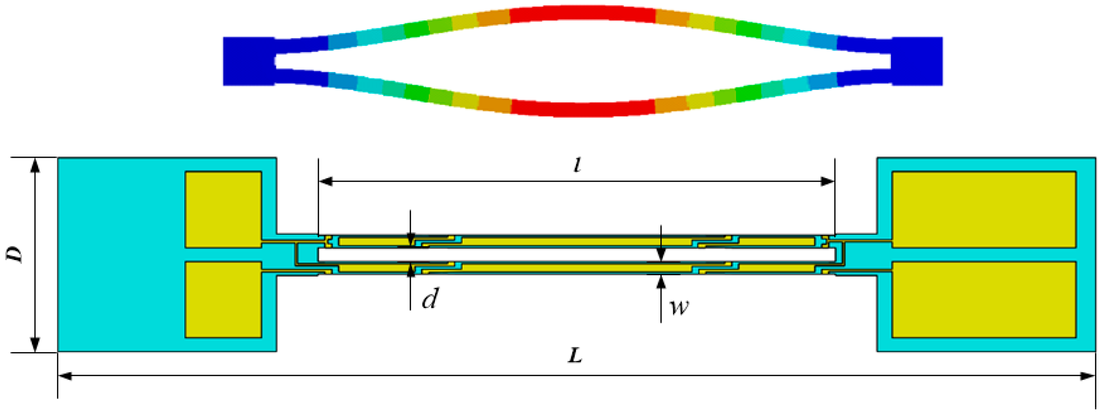
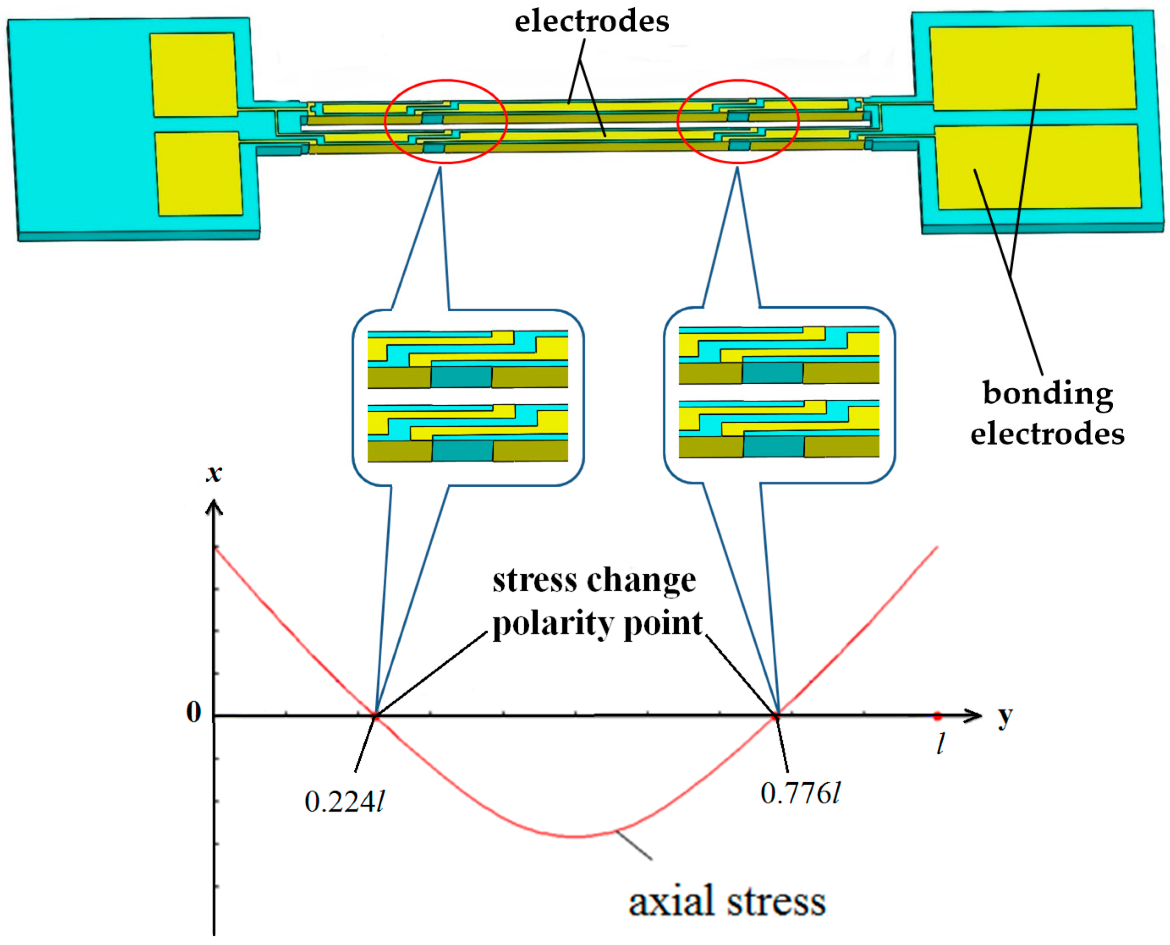
2.1. Design of the DETF
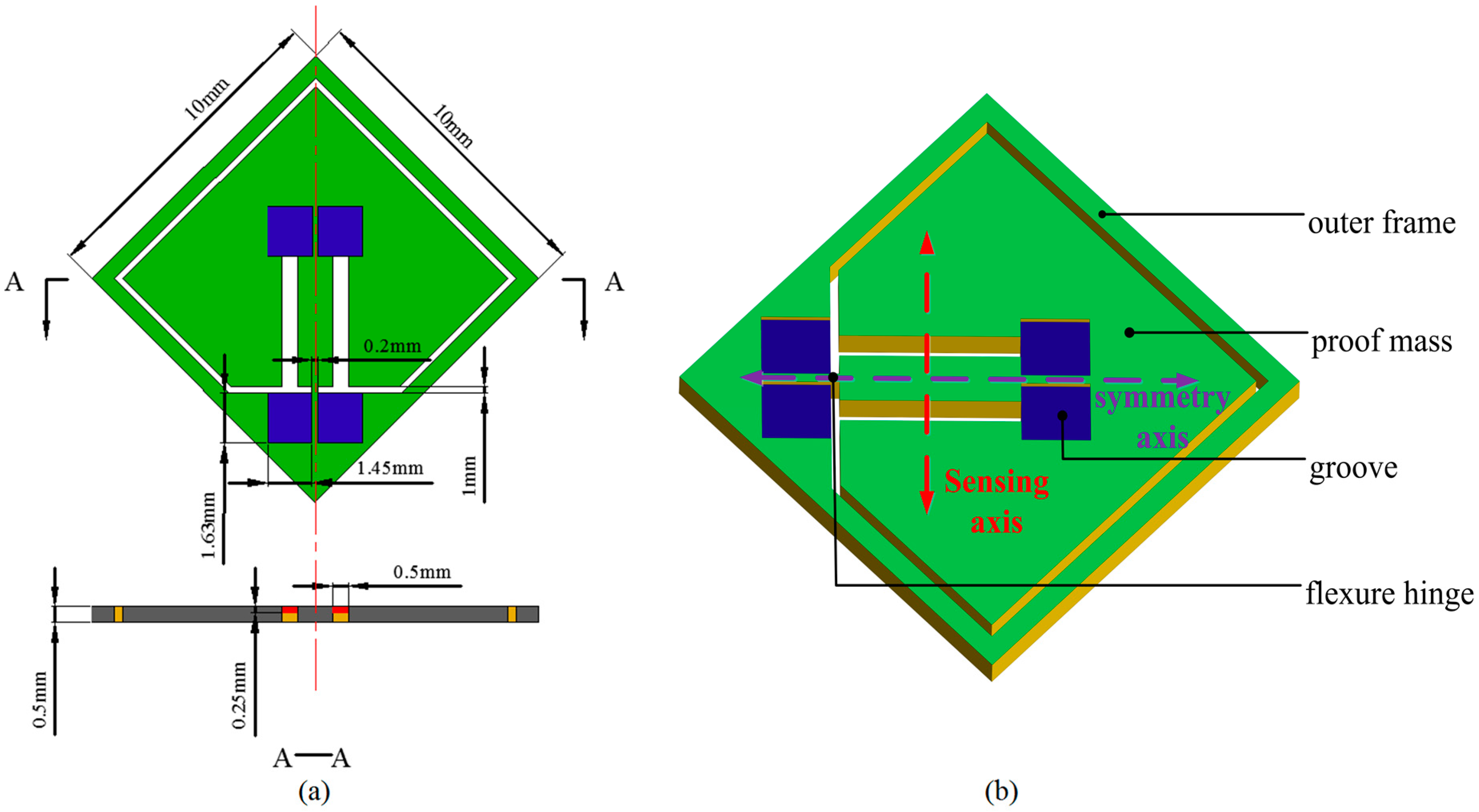
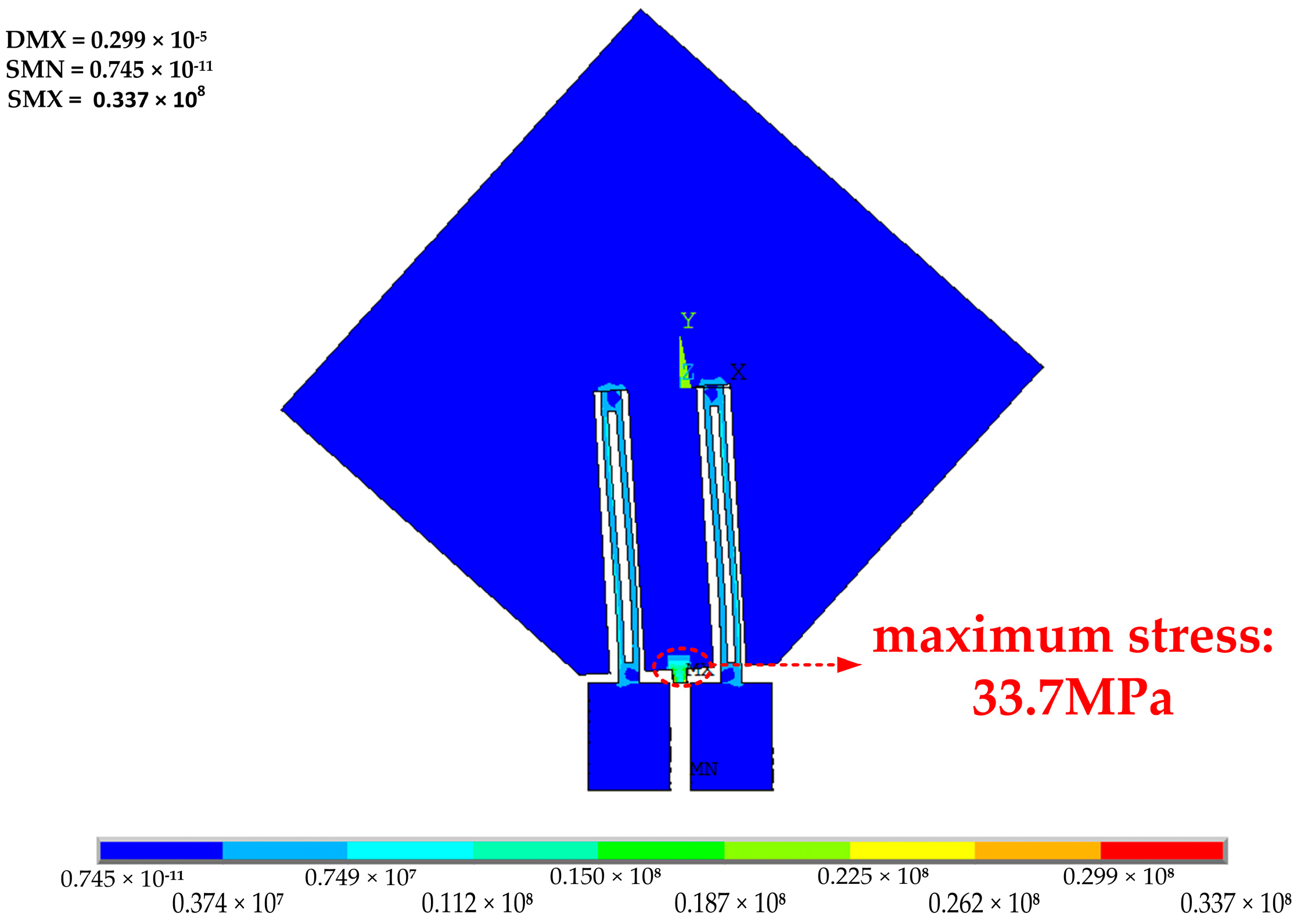
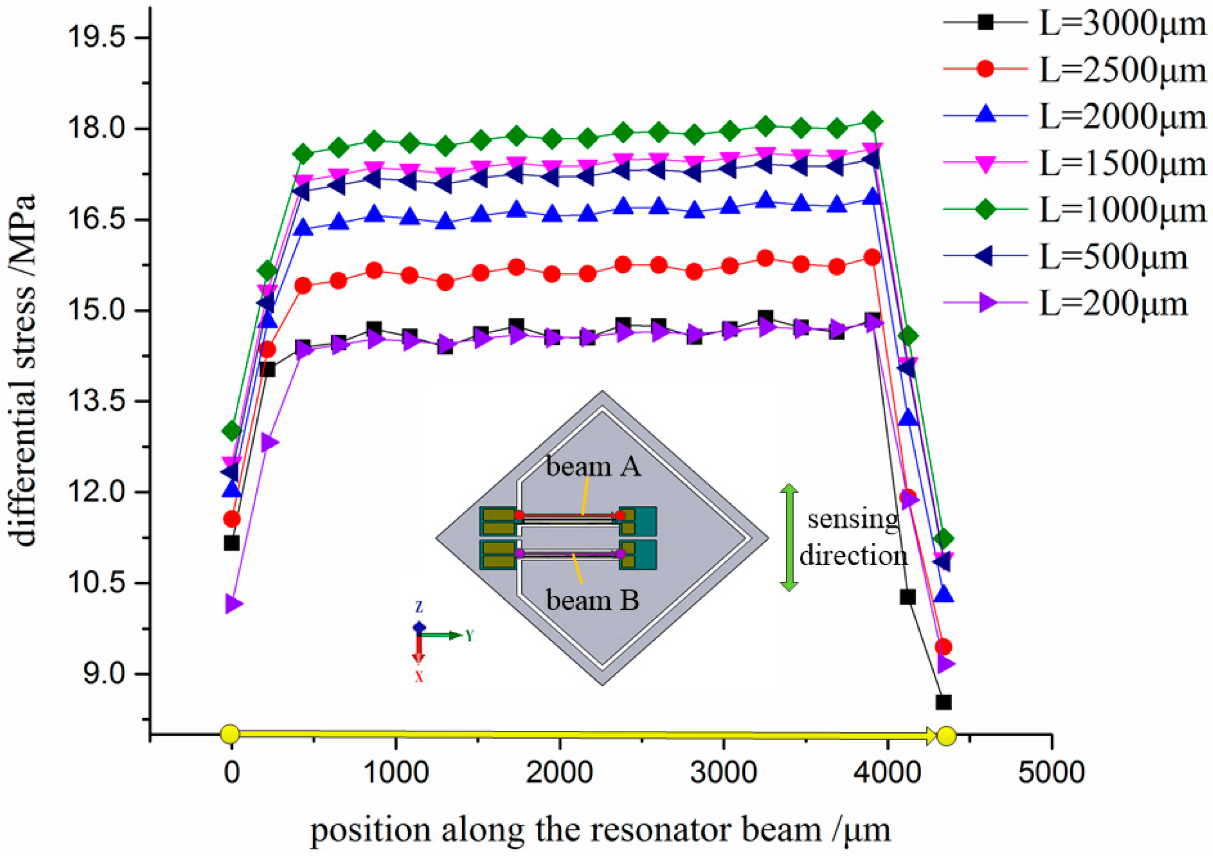
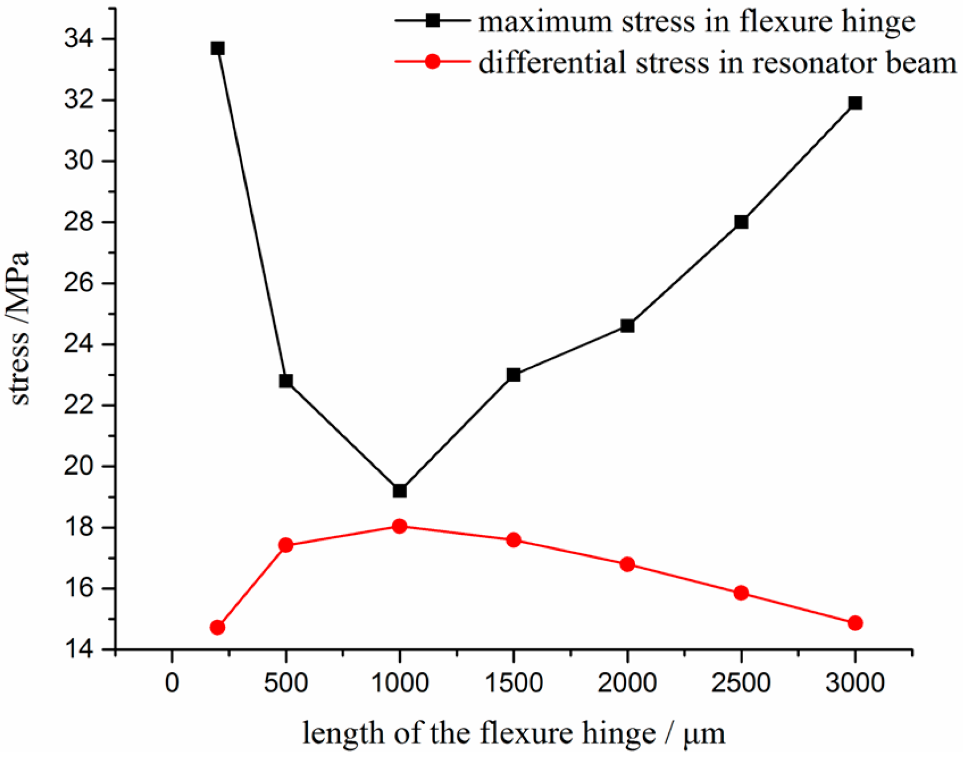
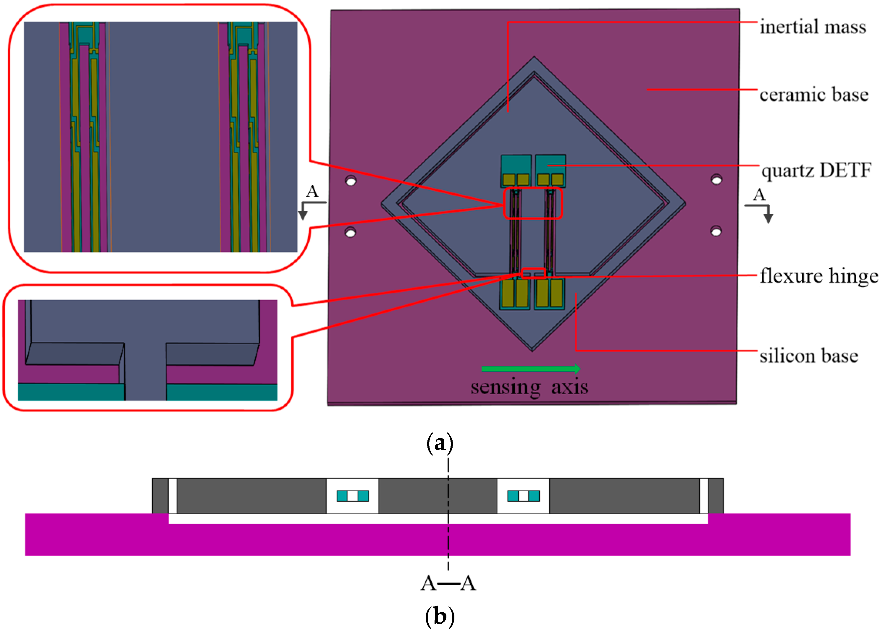
2.2. Design of Silicon Substrate
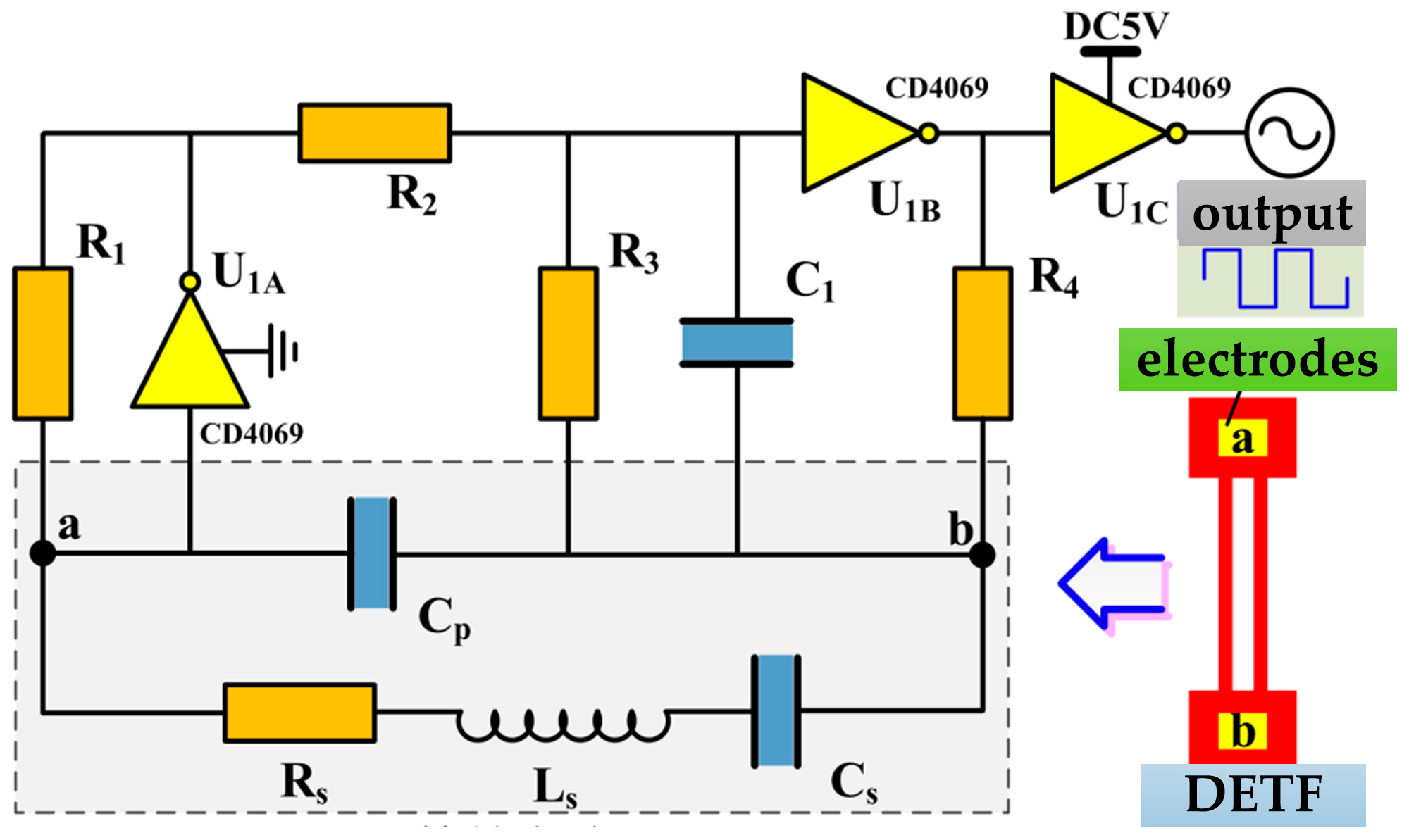
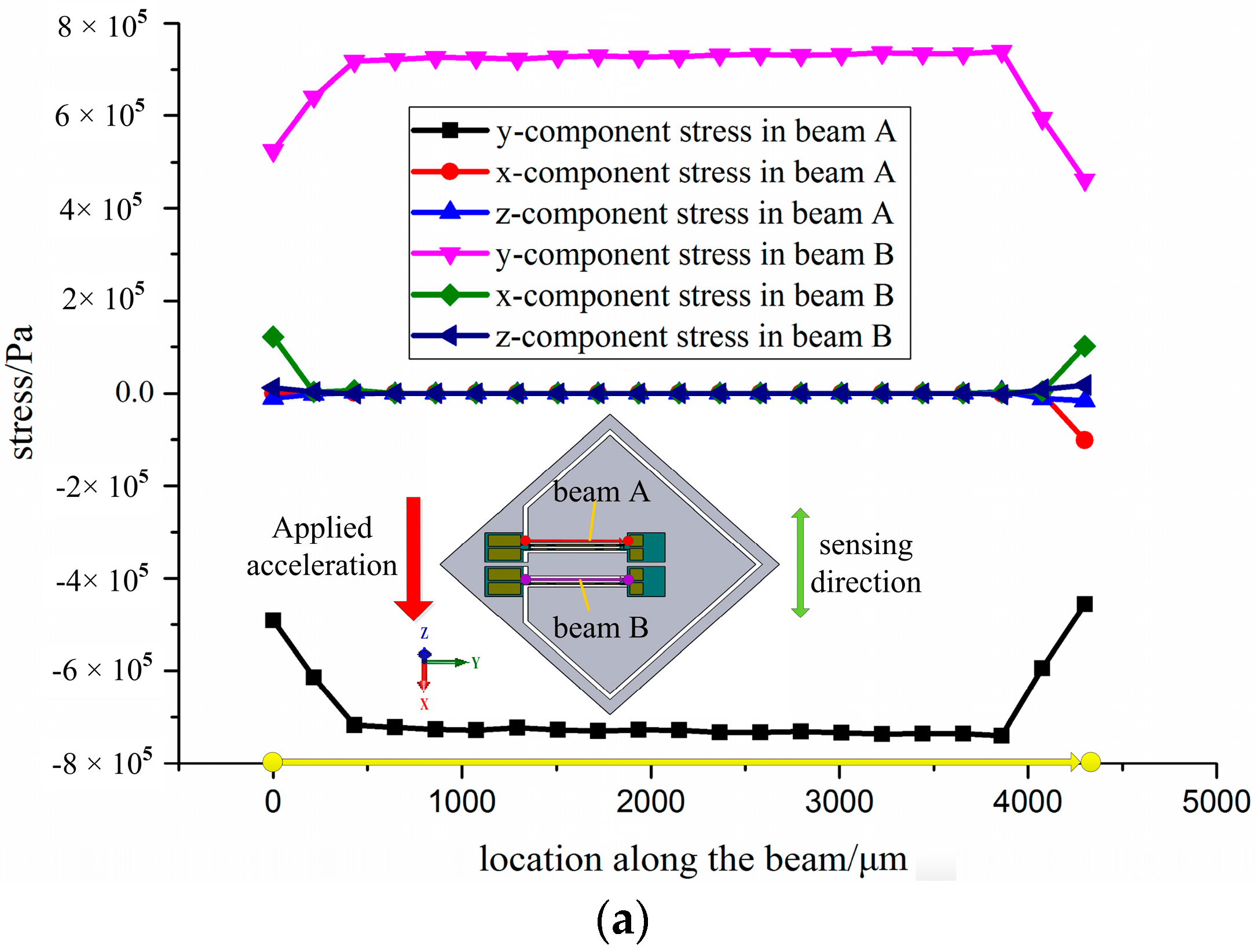
2.3. Operational Principle
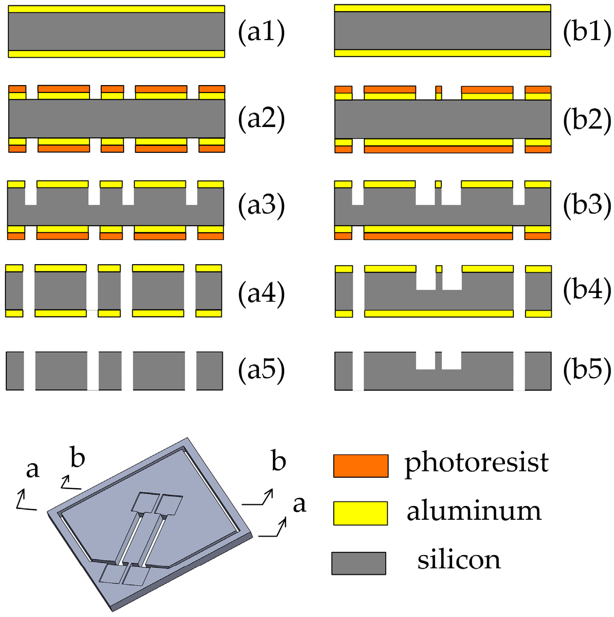
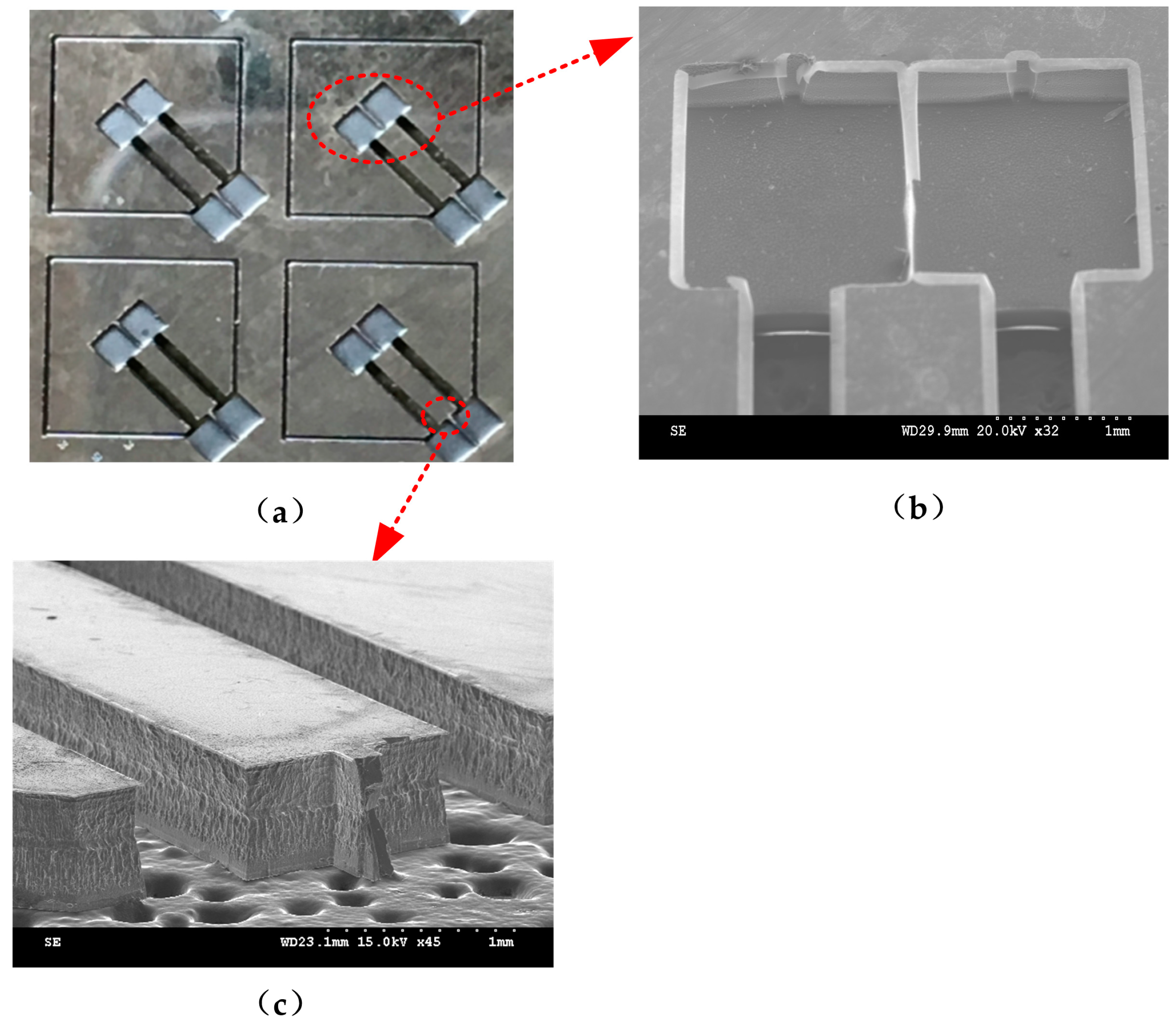
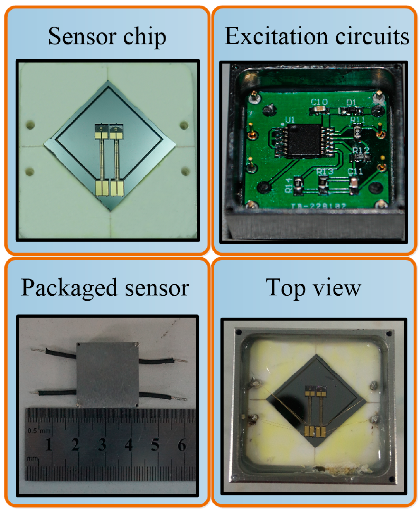
3. Fabrication
3.1. Fabrication of Silicon Substrate
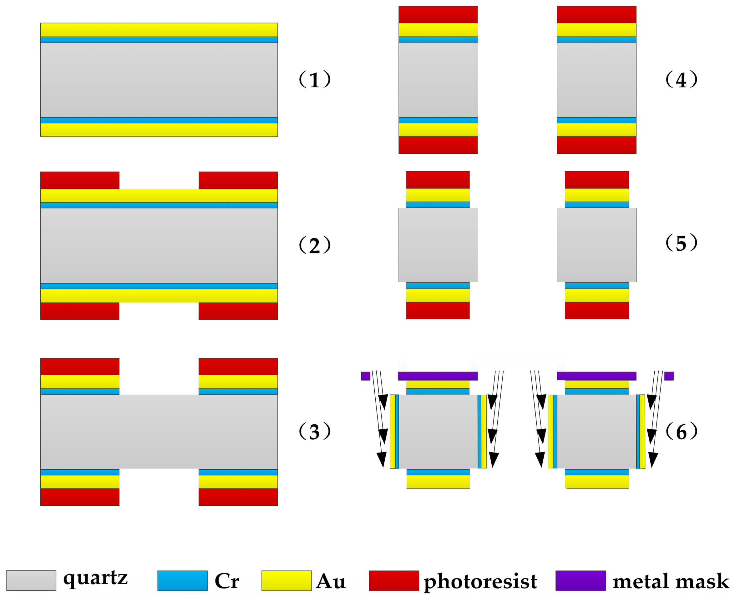
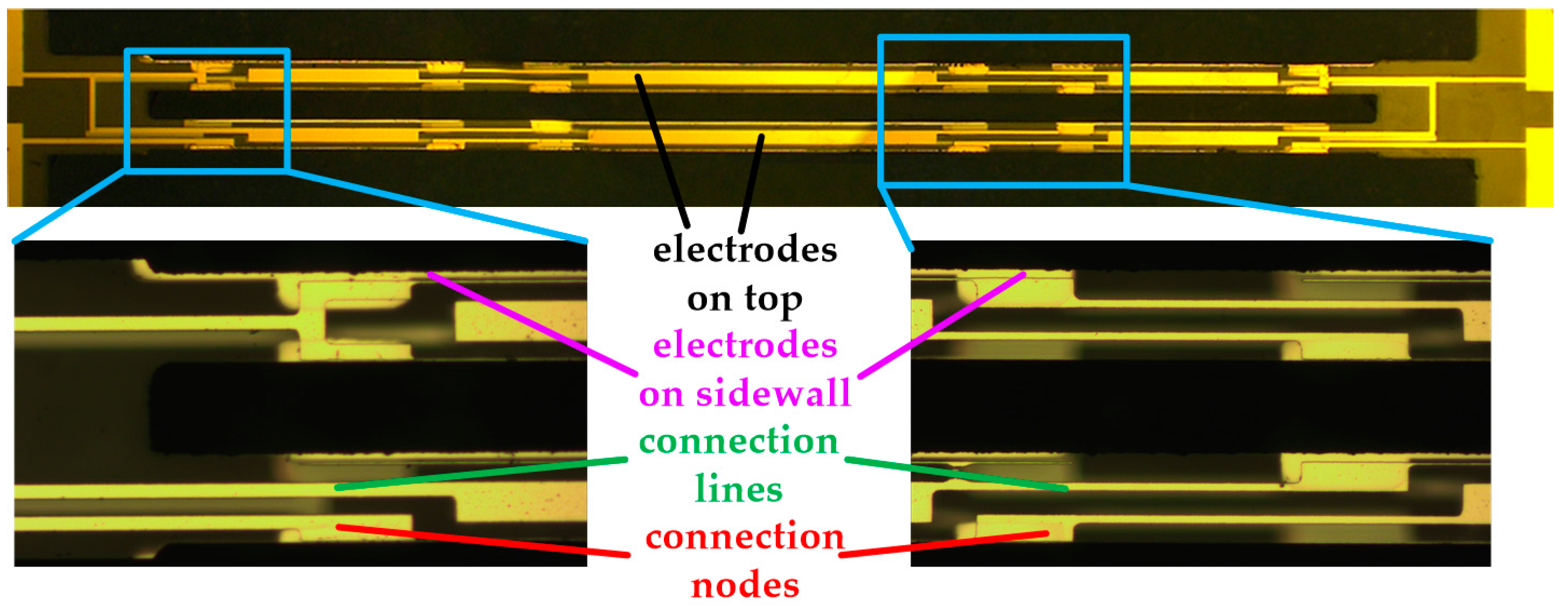
3.2. Fabrication of Quartz DETF
4. Experiment Results and Discussion
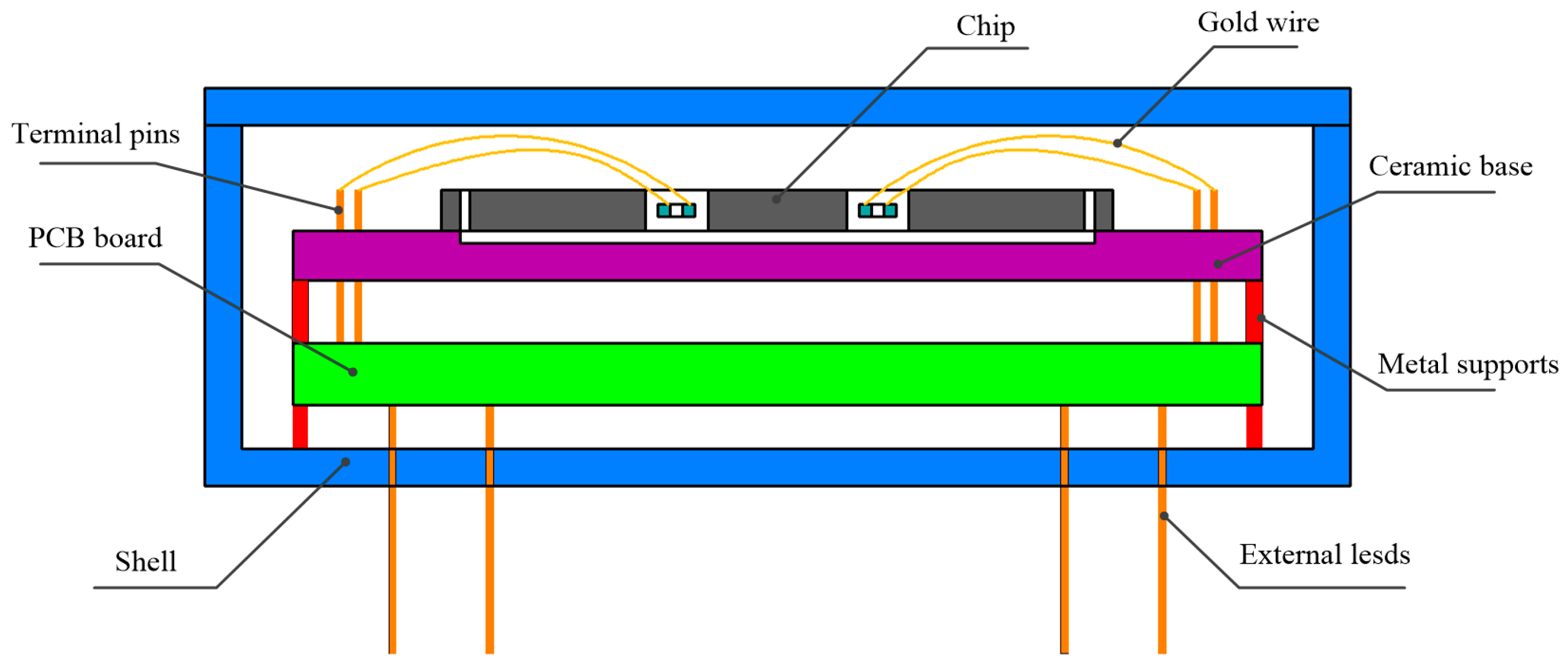
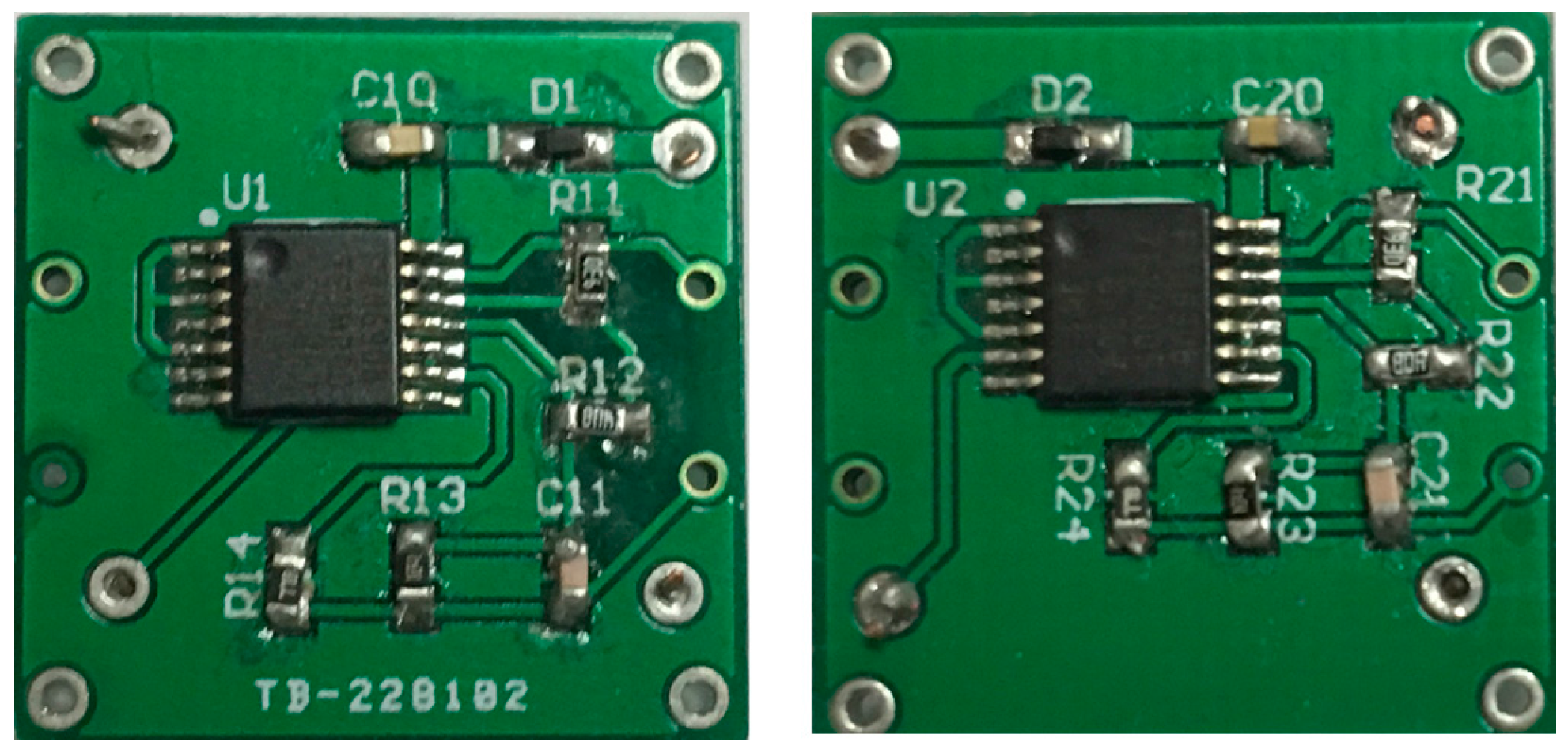
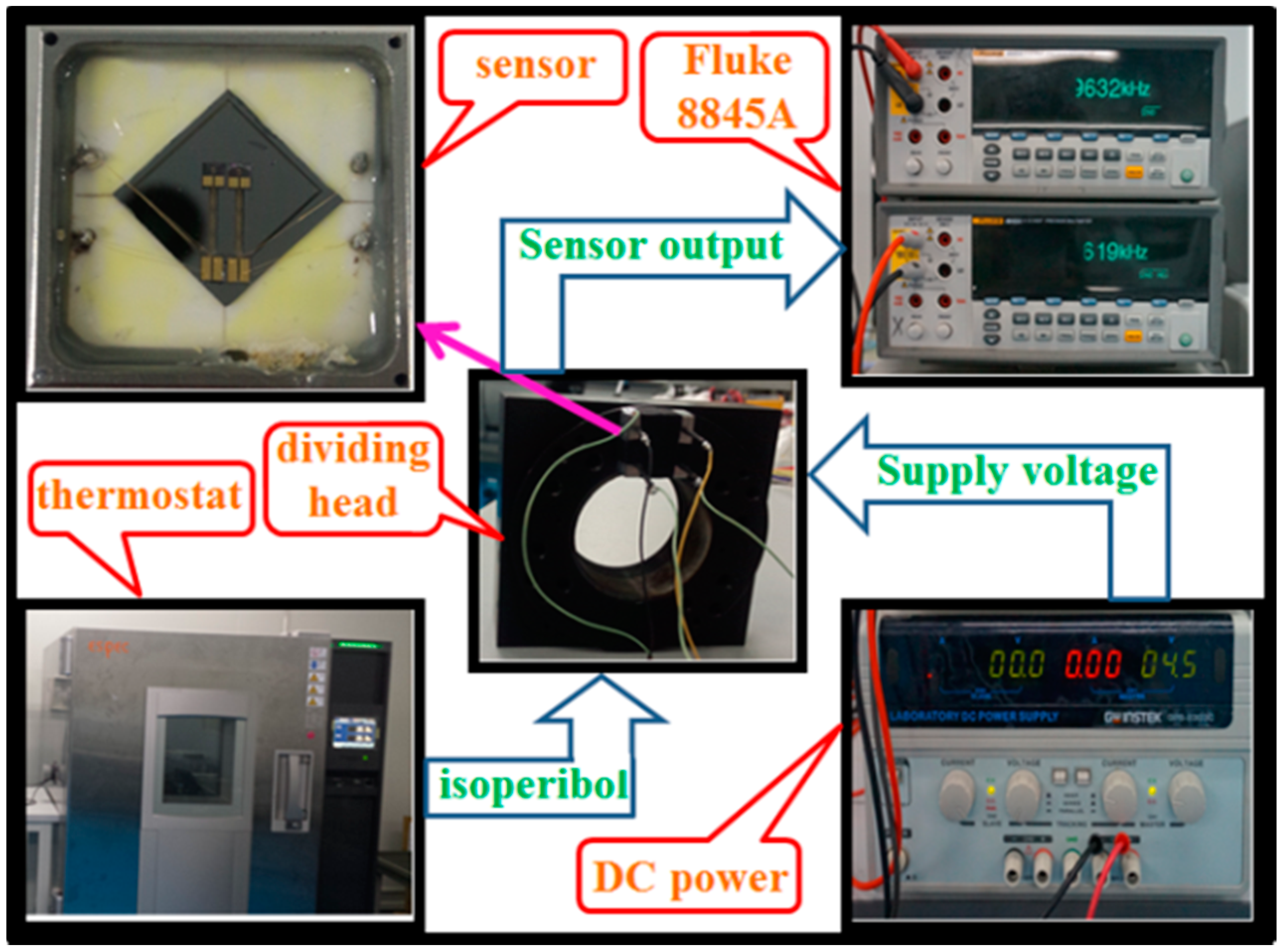
4.1. Packaging Process
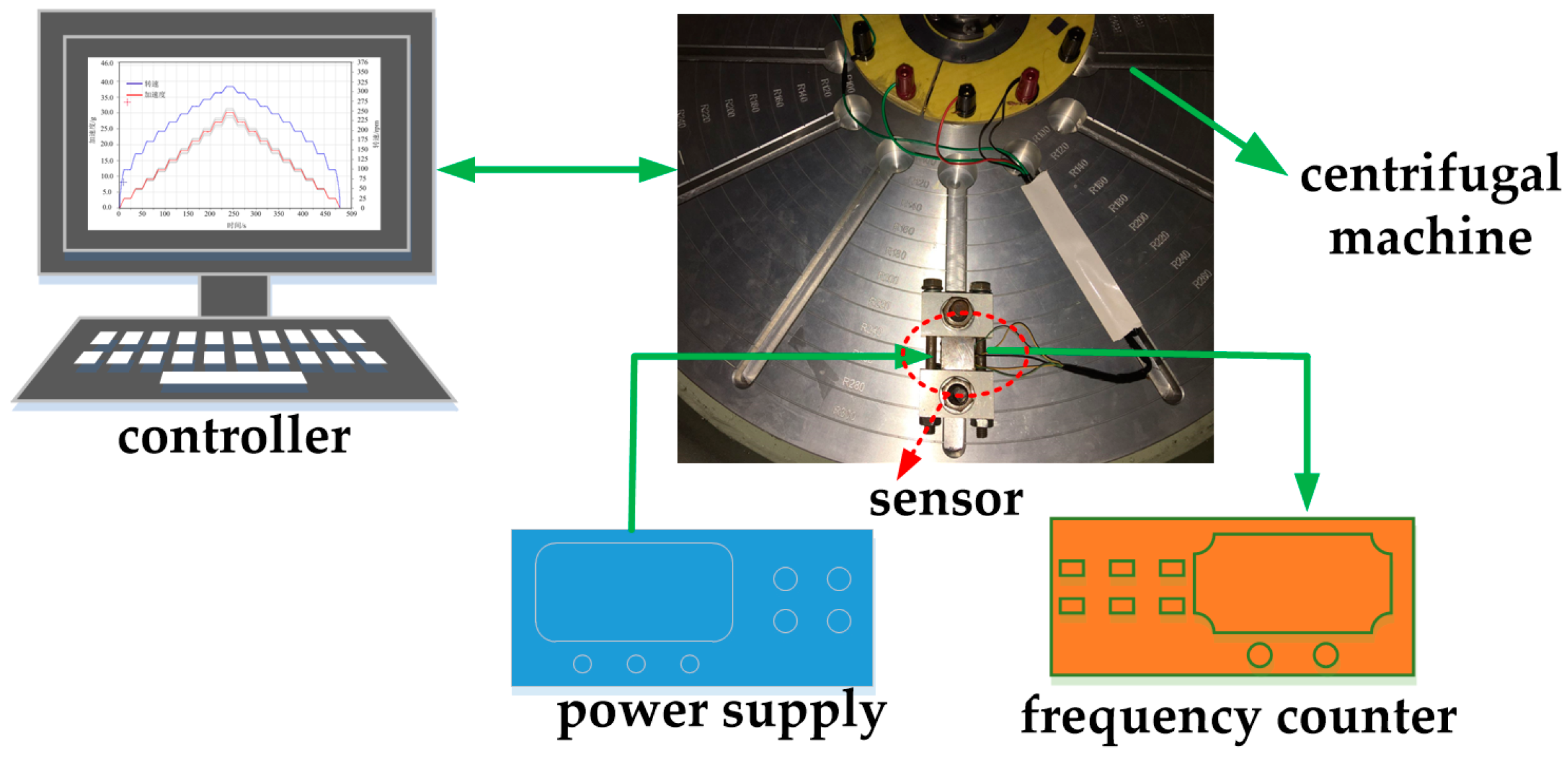
4.2. Static Experiments
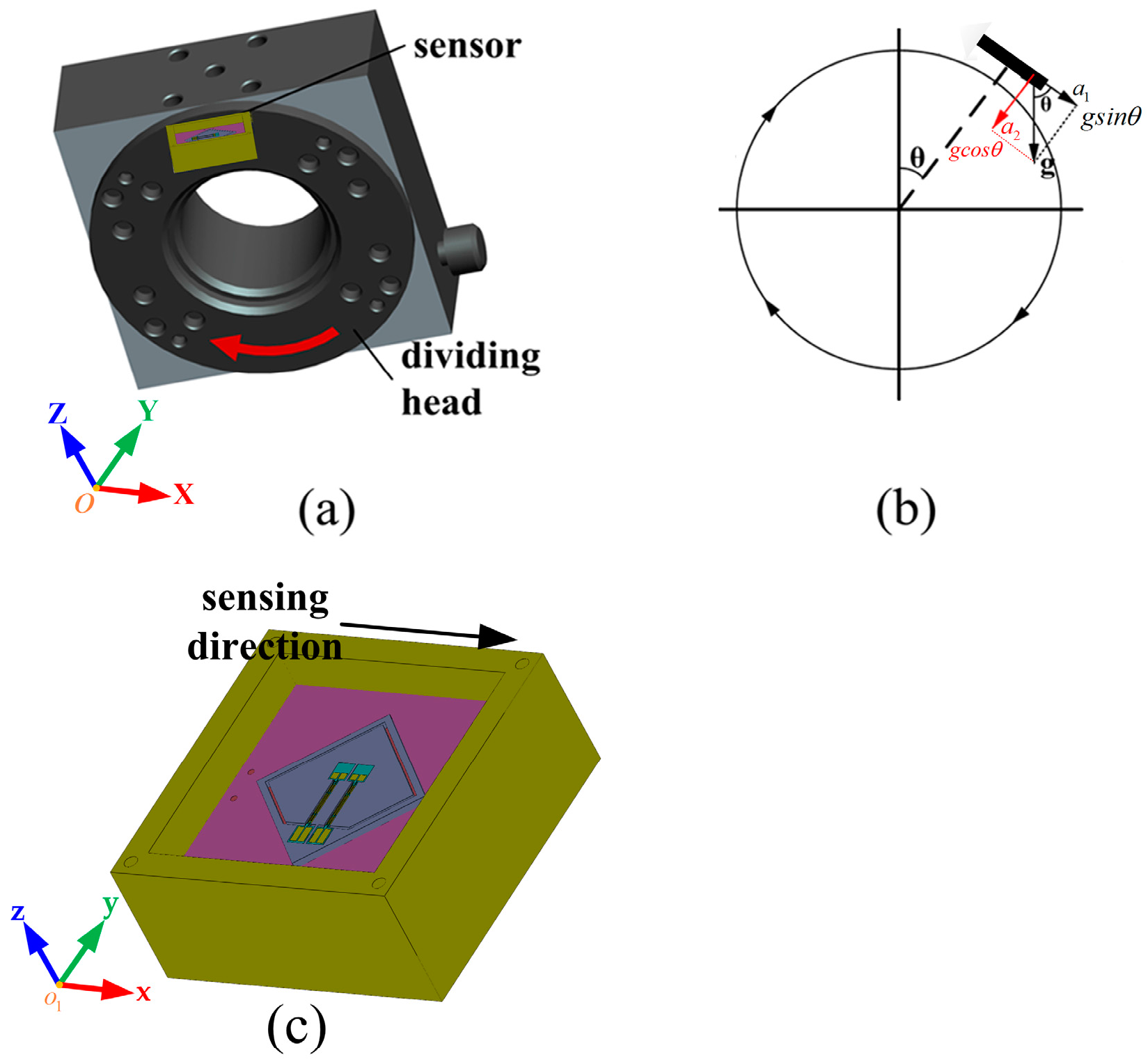
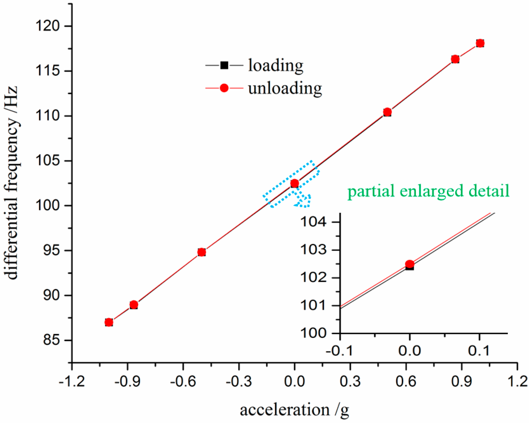
4.2.1. Tumbling Experiments
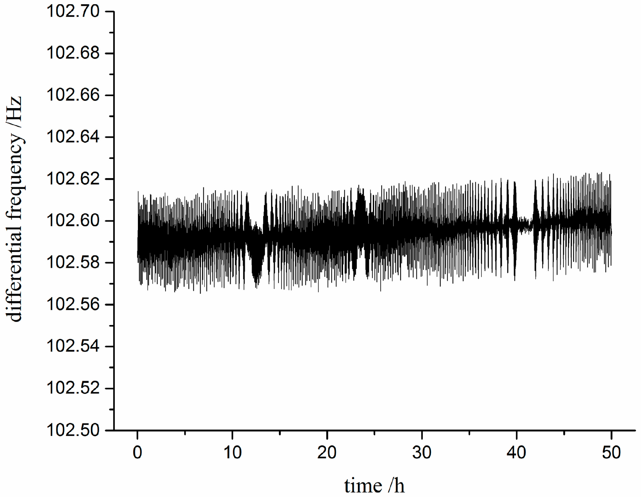
4.2.2. Static Stability Test
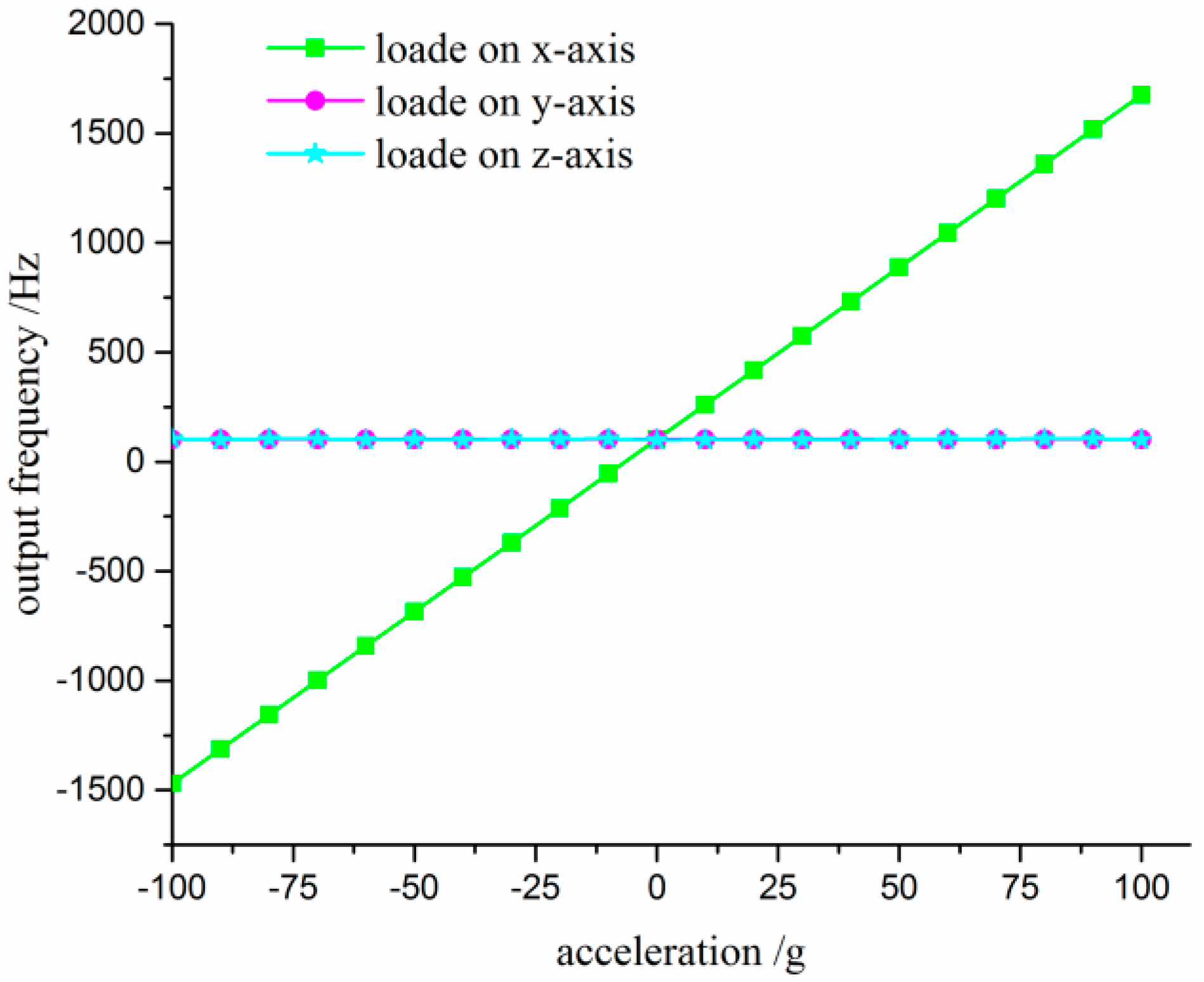
4.2.3. Cross-Interference Test
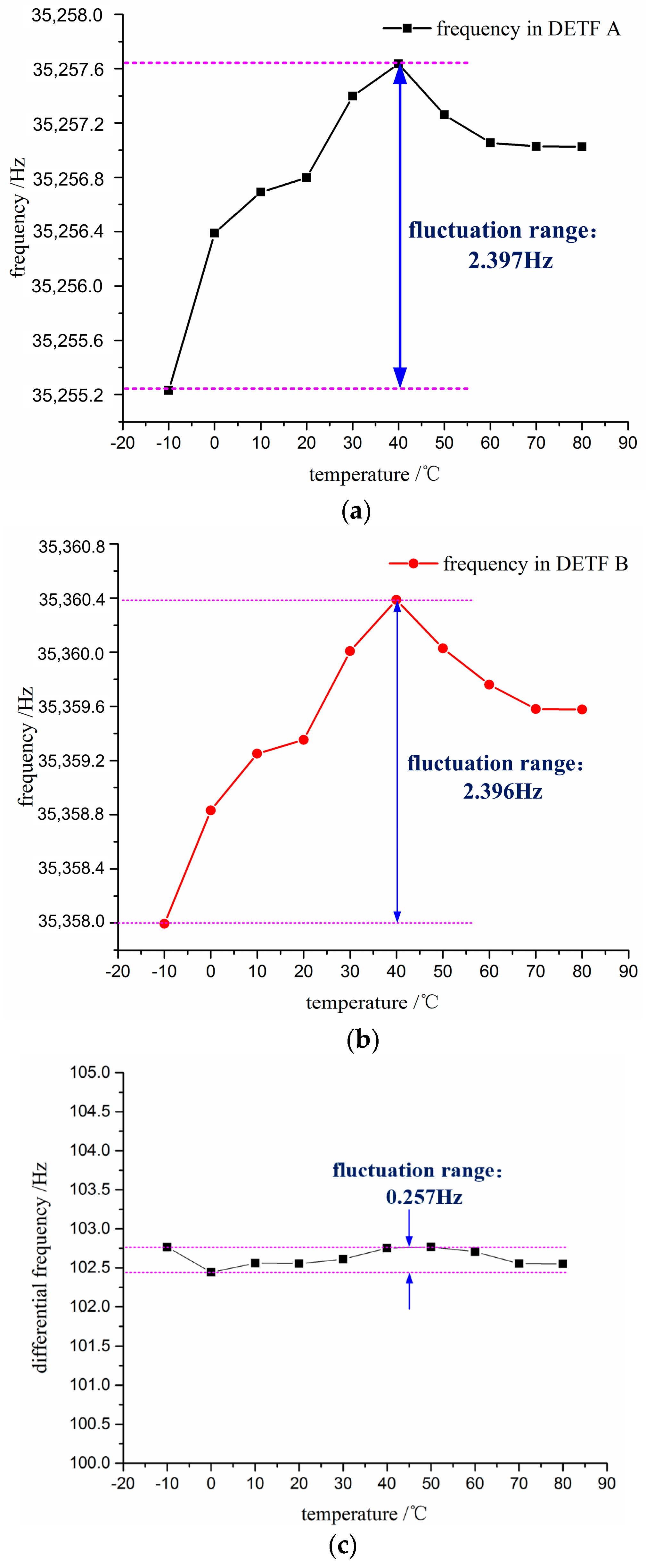
4.2.4. Test of Temperature Drift
4.3. Discussion
5. Conclusions
Acknowledgments
Author Contributions
Conflicts of Interest
References
- Macdonald, G.A. A review of low-cost accelerometers for vehicle dynamics. Sens. Actuators A 1990, 21, 303–307. [Google Scholar] [CrossRef]
- Bahreyni, B.; Najafi, F.; Shafai, C. Piezoresistive sensing with twin-beam structures in standard mems foundry processes. Sens. Actuators A 2006, 127, 325–331. [Google Scholar] [CrossRef]
- Yazdi, N.; Ayazi, F.; Najafi, K. Micromachined inertial sensors. Proc. IEEE 1998, 86, 1640–1659. [Google Scholar] [CrossRef]
- Lim, M.K.; Du, H.; Su, C.; Jin, W.L. A micromachined piezoresistive accelerometer with high sensitivity: Design and modelling. J. Microelectron. Eng. 1999, 49, 263–272. [Google Scholar] [CrossRef]
- Liu, S.F.; Ma, T.H.; Hou, W. Design and fabrication of a new miniaturized capacitive accelerometer. Sens. Actuators A 2008, 147, 70–74. [Google Scholar] [CrossRef]
- Seshia, A.A.; Palaniapan, M.; Roessig, T.A.; Howe, R.T.; Gooch, R.W.; Schimert, T.R.; Montague, S. A vacuum packaged surface micromachined resonant accelerometer. J. Microelectromech. Syst. 2002, 11, 784–793. [Google Scholar] [CrossRef]
- Barbour, N.; Schmidt, G. Inertial sensor technology trends. IEEE Sens. J. 2001, 1, 332–339. [Google Scholar] [CrossRef]
- Ferrari, V.; Ghisla, A.; Marioli, D.; Taroni, A. Silicon resonant accelerometer with electronic compensation of input-output cross-talk. Sens. Actuators A 2005, 123–124, 258–266. [Google Scholar] [CrossRef]
- Comi, C.; Corigliano, A.; Langfelder, G.; Longoni, A.; Tocchio, A.; Simoni, B. A resonant microaccelerometer with high sensitivity operating in an oscillating circuit. J. Microelectromech. Syst. 2010, 19, 1140–1152. [Google Scholar] [CrossRef]
- Tocchio, A.; Caspani, A.; Langfelder, G.; Longoni, A.; Lasalandra, E. Resolution and start-up dynamics of mems resonant accelerometers. In Proceedings of the 2011 IEEE Sensors, Limerick, Ireland, 28–31 October 2011; pp. 161–164.
- Beeby, S.P.; Ensell, G.; Baker, B.R.; Tudor, M.J.; White, N.M. Micromachined silicon resonant strain gauges fabricated using soi wafer technology. J. Microelectromech. Syst. 2000, 9, 104–111. [Google Scholar] [CrossRef]
- Cortés-Pérez, A.R.; Herrera-May, A.L.; Aguilera-Cortés, L.A.; González-Palacios, M.A.; Torres-Cisneros, M. Performance optimization and mechanical modeling of uniaxial piezoresistive microaccelerometers. Microsyst. Technol. 2010, 16, 461–476. [Google Scholar] [CrossRef]
- Ding, H.; Zhao, J.; Ju, B.F.; Xie, J. A high-sensitivity biaxial resonant accelerometer with two-stage microleverage mechanisms. J. Micromech. Microeng. 2016, 26, 015011. [Google Scholar] [CrossRef]
- Wang, J.; Shang, Y.; Chen, J.; Sun, Z. Micro-machined resonant out-of-plane accelerometer with a differential structure fabricated by silicon-on-insulator–mems technology. Micro Nano Lett. 2010, 7, 1230–1233. [Google Scholar] [CrossRef]
- Yang, B.; Wang, X.; Dai, B.; Liu, X. A new z-axis resonant micro-accelerometer based on electrostatic stiffness. Sensors 2015, 15, 478–483. [Google Scholar] [CrossRef] [PubMed]
- Li, C.; Zhao, Y.; Cheng, R.; Yu, Z.; Liu, Y. A resonant sensor composed of quartz double ended tuning fork and silicon substrate for digital acceleration measurement. Rev. Sci. Instrum. 2014, 85, 035004. [Google Scholar] [CrossRef] [PubMed]
- Comi, C.; Corigliano, A.; Langfelder, G.; Zega, V.; Zerbini, S.; Comi, C.; Corigliano, A.; Langfelder, G.; Zega, V.; Zerbini, S. Sensitivity and temperature behavior of a novel z-axis differential resonant micro accelerometer. J. Micromech. Microeng. 2016, 26, 1–11. [Google Scholar] [CrossRef]
- Greenwood, J.C. Etched silicon vibrating sensor. J. Phys. E-Sci. Instrum. 1984, 17, 650–652. [Google Scholar] [CrossRef]
- Roessig, T.A.; Howe, R.T.; Pisano, A.P. Nonlinear mixing in surface-micromachined tuning fork oscillators. In Proceedings of the 1997 IEEE International Frequency Control Symposium, Toronto, ON, Canada, 5–8 October 1997; pp. 778–782.
- Olsson, R.H.; Wojciechowski, K.E.; Baker, M.S.; Tuck, M.R.; Fleming, J.G. Post-cmos-compatible aluminum nitride resonant mems accelerometers. J. Microelectromech. Syst. 2009, 18, 671–678. [Google Scholar] [CrossRef]
- Satchell, D.W.; Greenwood, J.C. A thermally-excited silicon accelerometer. Sens. Actuators 1989, 17, 241–245. [Google Scholar] [CrossRef]
- Chen, D.Y.; Wu, Z.W.; Liu, L.; Shi, X.J.; Wang, J.B. An electromagnetically excited silicon nitride beam resonant accelerometer. Sensors 2009, 9, 1330–1338. [Google Scholar] [CrossRef] [PubMed]
- Albert, W.C. Vibrating quartz crystal beam accelerometer. In Proceedings of the 28th International Instrumentation Symposium, Las Vegas, NV, USA, 3–6 May 1982; pp. 33–44.
- Kass, W.J.; Snow, G.S. Double-ended tuning fork quartz accelerometer characteristics. IEEE Trans. Ultrason. Ferroelectr. Freq. Control 1986, 33, 792. [Google Scholar]
- Norling, B.L.; Cornelius, C.J. Accelerometer with Isolator for Common Mode Inputs. U.S. Patent 4,766,768 A, 30 August 1988. [Google Scholar]
- Traon, O.L.; Janiaud, D.; Lecorre, B.; Pernice, M.; Muller, S.; Tridera, J.Y. Monolithic differential vibrating beam accelerometer within an isolating system between the two resonators. In Proceedings of the 2005 IEEE Sensors, Irvine, CA, USA, 30 October–3 November 2005; pp. 648–651.
- Traon, O.L.; Janiaud, D.; Pernice, M.; Masson, S.; Muller, S.; Tridera, J.Y. A new quartz monolithic differential vibrating beam accelerometer. In Proceedings of the 2006 IEEE/Ion Position, Location and Navigation Symposium, Coronado, CA, USA, 25–27 April 2006; pp. 6–15.
- Shang, Y.; Wang, J.; Tu, S.; Chen, D. A novel micromachined differential resonant accelerometer with flexural mechanisms fabricated by soi-mems technology. In Proceedings of the 2011 IEEE Sensors, Limerick, Ireland, 28–31 October 2011; pp. 165–168.
- Su, W.; Zhang, F.T.; Liu, H. A resonant accelerometer based on electrostatic stiffness and its closed-loop control method. Sens. Rev. 2011, 31, 58–64. [Google Scholar] [CrossRef]
- Cheshmehdoost, A.; Jones, B.E. Design and performance characteristics of an integrated high-capacity detf-based force sensor. Sens. Actuators A 1996, 52, 99–102. [Google Scholar] [CrossRef]
- Chuang, S.S. Force sensor using double-ended tuning fork quartz crystals. IEEE Trans. Sonics Ultrason. 1983, 30, 388. [Google Scholar]
- Gan, Z.; Lin, D.; Wang, X.; Chenggang; Zhang, H.; Liu, S. Vacuum measurement on vacuum packaged mems devices. In Proceedings of the International Symposium on Instrumentation Science and Technology, Harbin, China, 8–12 August 2006; pp. 1429–1434.
- Marinis, T.F.; Soucy, J.W. Vacuum packaging of mems inertial sensors. In Proceedings of the IMAPS International Symposium on Microelectronics, Boston, MA, USA, 18–20 November 2003.


| Parameters | Total length L (mm) | Total width D (mm) | Length of the Tines l (mm) | Width of the Tines w (μm) | Space between the Tines d (μm) | Thickness of the Tines t (μm) | Initial Frequency (kHz) |
|---|---|---|---|---|---|---|---|
| Values | 7.5 | 1.4 | 3.55 | 90 | 100 | 100 | 35.309 |
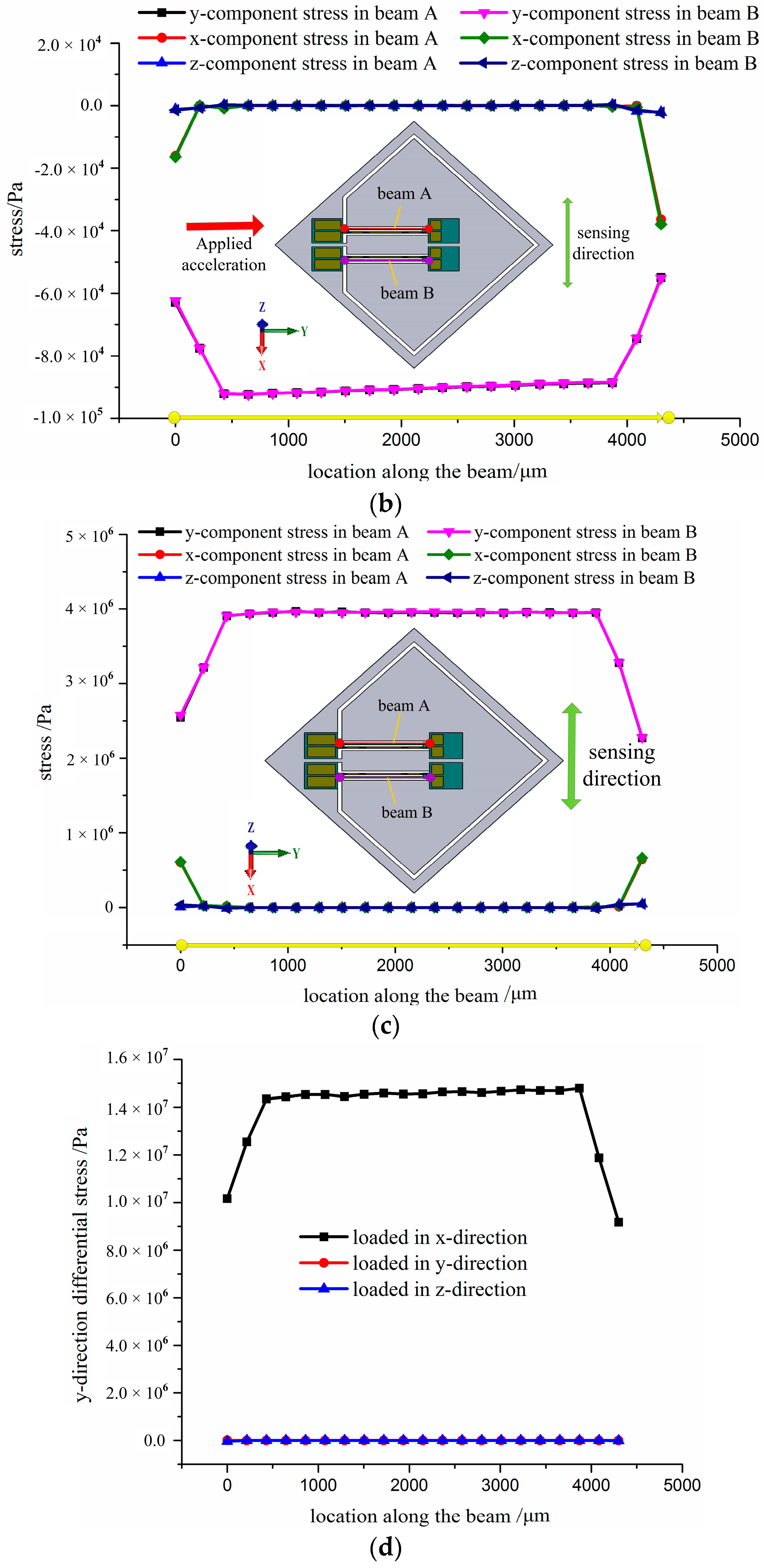
| Direction of the Acceleration Loaded | Maximum Differential Stress of x-Component (MPa) | Maximum Differential Stress of y-Component (MPa) | Maximum Differential Stress of z-Component (MPa) |
|---|---|---|---|
| x-axis | 0.00048 | 14.7 | 0.00036 |
| y-axis | 0.0009 | 0.00025 | 0.00065 |
| z-axis | 0.00014 | 0.000172 | 0.000354 |
© 2017 by the authors; licensee MDPI, Basel, Switzerland. This article is an open access article distributed under the terms and conditions of the Creative Commons Attribution (CC-BY) license (http://creativecommons.org/licenses/by/4.0/).
Share and Cite
Li, B.; Zhao, Y.; Li, C.; Cheng, R.; Sun, D.; Wang, S. A Differential Resonant Accelerometer with Low Cross-Interference and Temperature Drift. Sensors 2017, 17, 178. https://doi.org/10.3390/s17010178
Li B, Zhao Y, Li C, Cheng R, Sun D, Wang S. A Differential Resonant Accelerometer with Low Cross-Interference and Temperature Drift. Sensors. 2017; 17(1):178. https://doi.org/10.3390/s17010178
Chicago/Turabian StyleLi, Bo, Yulong Zhao, Cun Li, Rongjun Cheng, Dengqiang Sun, and Songli Wang. 2017. "A Differential Resonant Accelerometer with Low Cross-Interference and Temperature Drift" Sensors 17, no. 1: 178. https://doi.org/10.3390/s17010178