
A New Controller for a Smart Walker Based on Human-Robot Formation

 , and
, and
Abstract
:1. Introduction
1.1. Smart Walkers
- RT Walker: this is a passive walker, which contains a laser sensor to monitor the surrounding area and two other laser sensors to find the user’s legs. In addition, this walker also contains inclinometers to find the walker inclination [31].
- GUIDO Smart Walker: this walker had its first version (PAM-AID walker) developed to assist blind people [32]. Throughout time, this walker received new sensors, other control strategies and, currently, has ultrasound or a laser sensor (depending on the version) to help users avoid obstacles [29]. They do not offer propulsion, being classified as a passive walker [33]. The current version of this walker can also perform SLAM (simultaneous localization and mapping), which allows the device with mapping the environment (while assisting the user) and using this information to detect obstacles [27].
- JARoW: this walker uses omni-directional wheels to improve its maneuverability. Two infrared sensors are used to detect the user’s legs in order to control the walker speed [34].
- Other devices: there are several other devices, with different techniques and purposes. The SIMBIOSIS Smart Walker, for example, was designed to study human gait [35]; the PAMM (Personal Assistant for Mobility and Monitoring) monitors the user’s health while he/she uses the device [36]; the iWalker was developed to be used inside a structured environment using local sensors and others in the environment [30]. These walkers are focused either on elderly people or to study human gait.
2. Materials and Methods
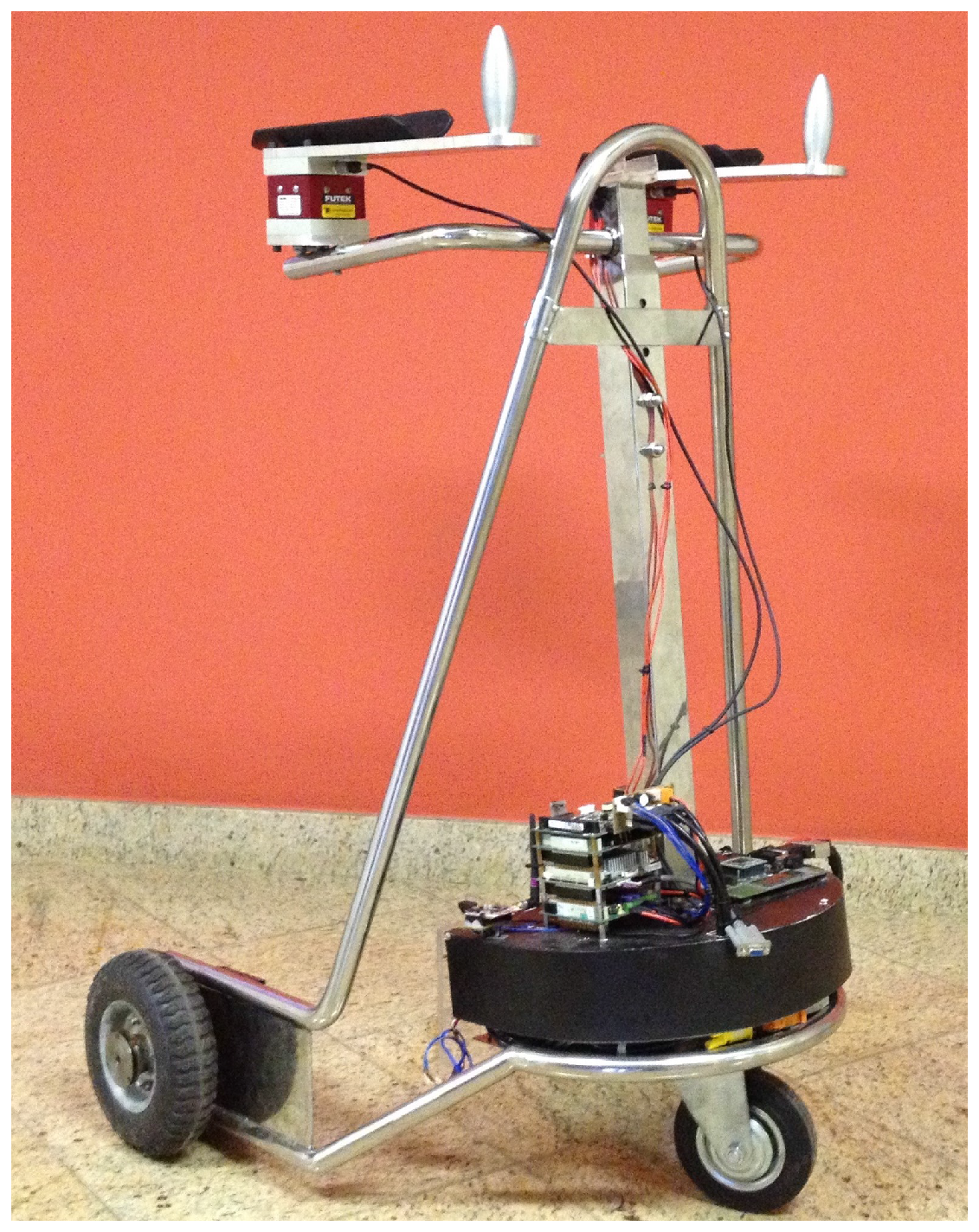
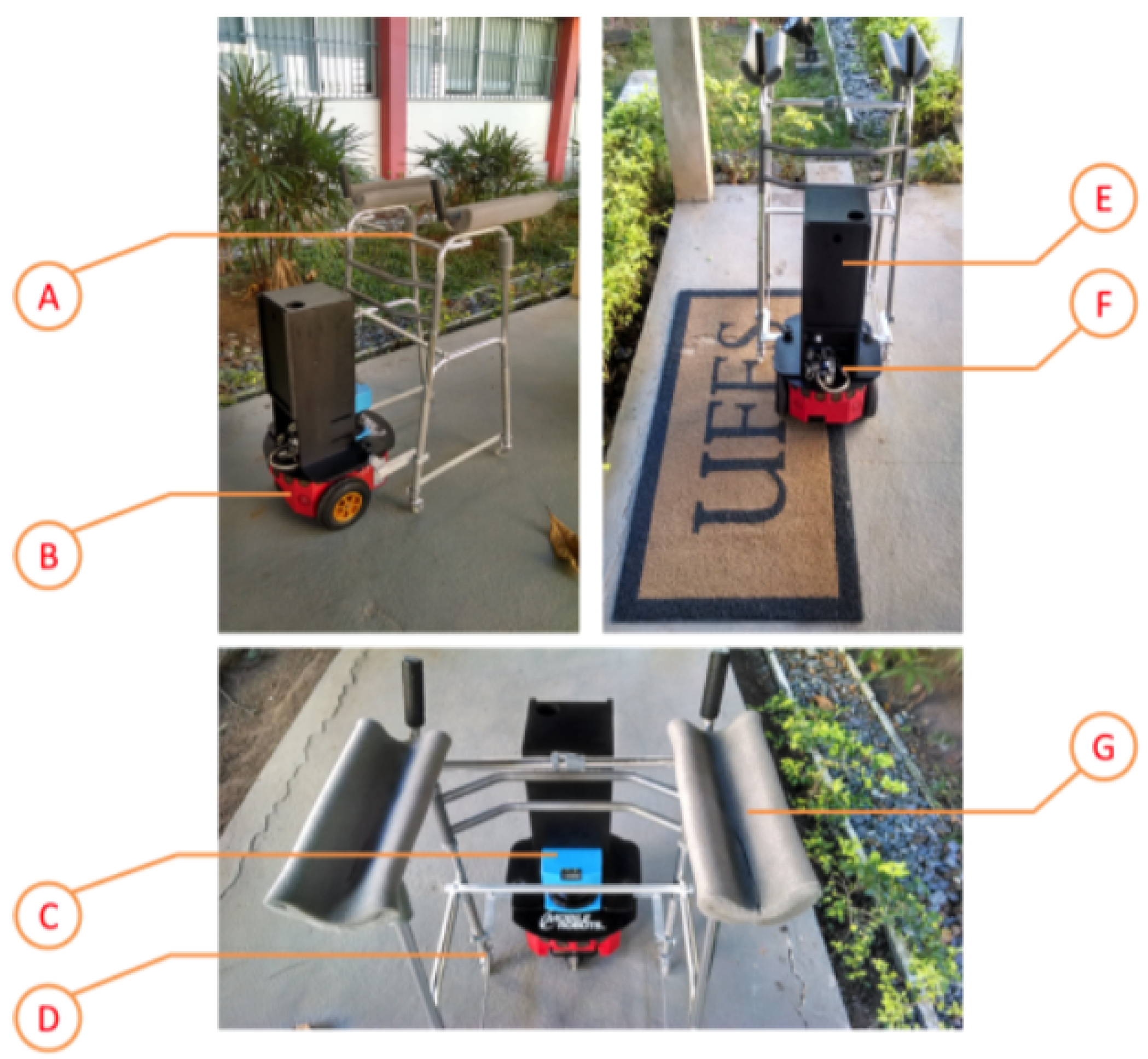
2.1. Mechanical Structure and Hardware
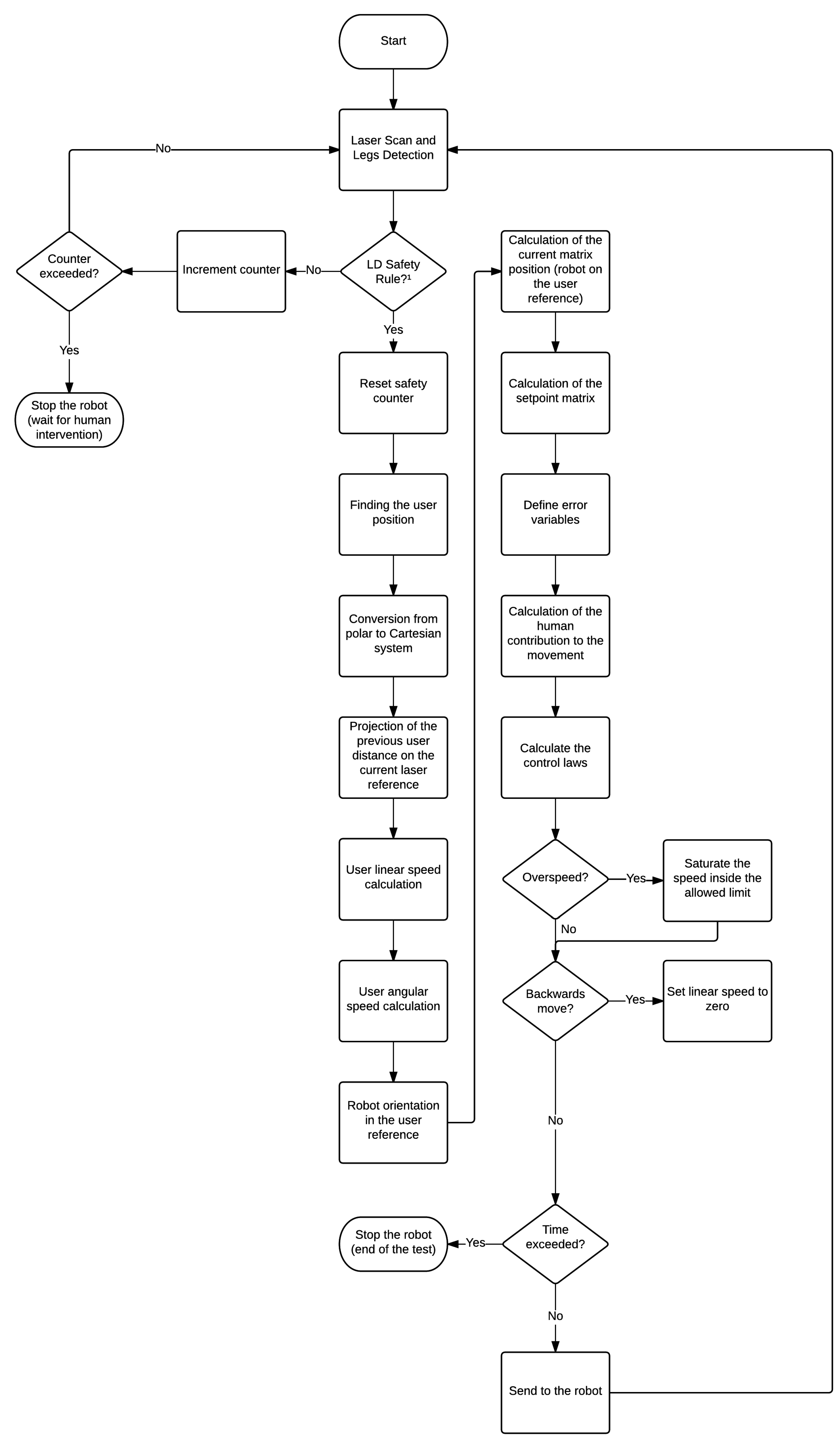
2.2. Algorithms
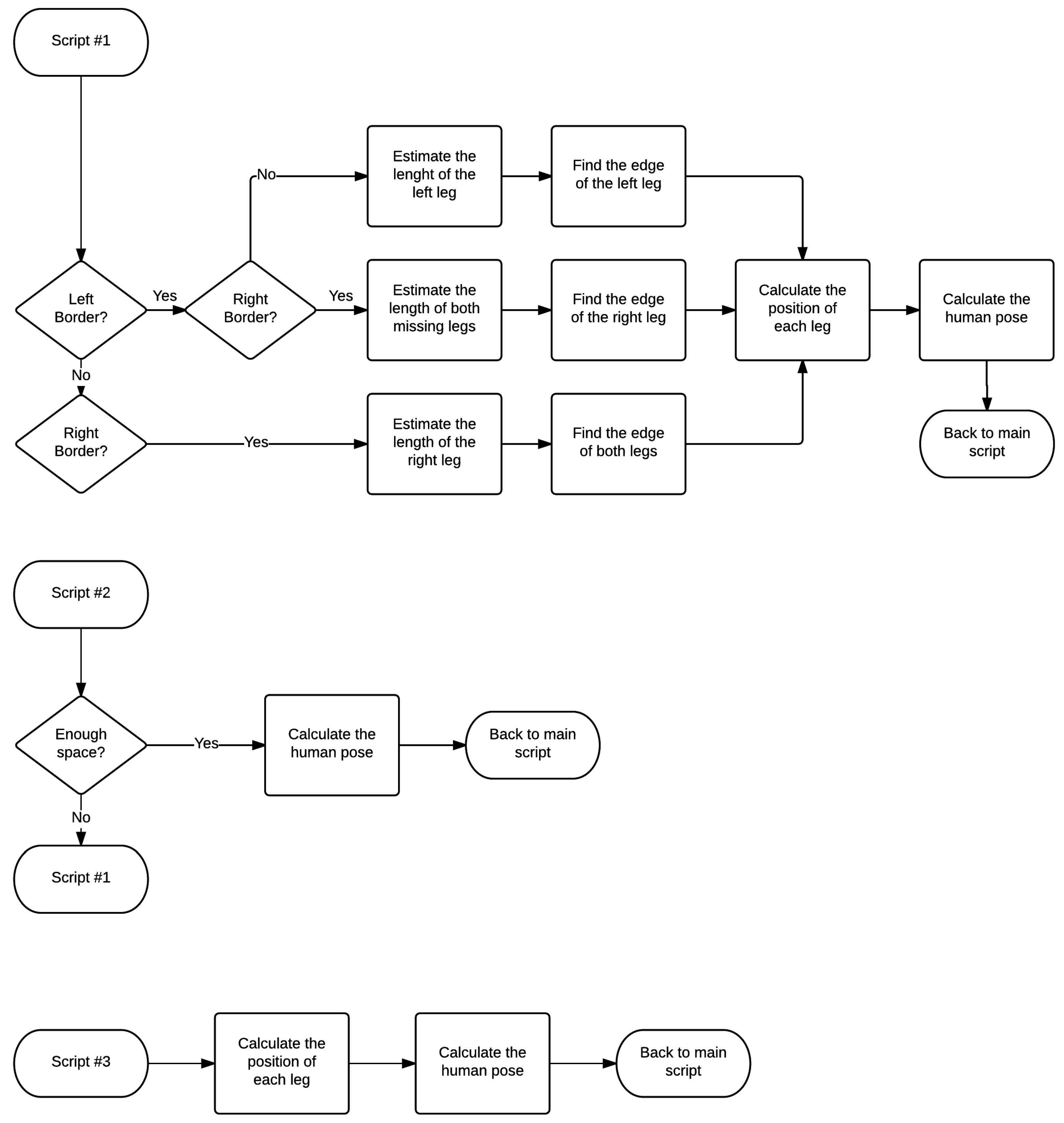
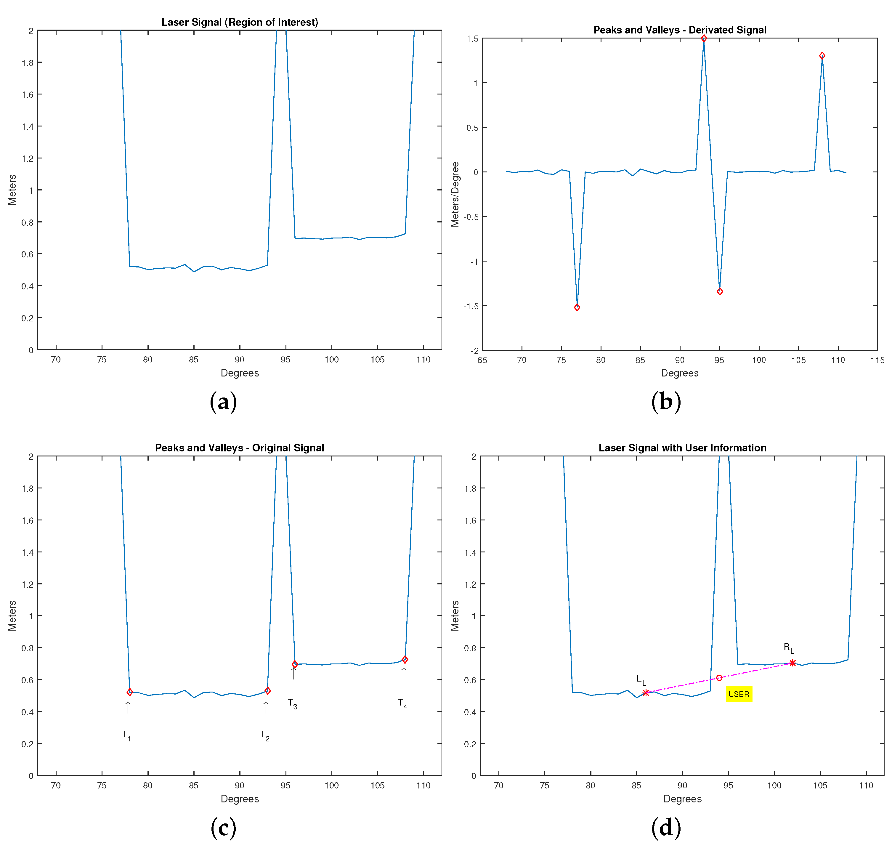
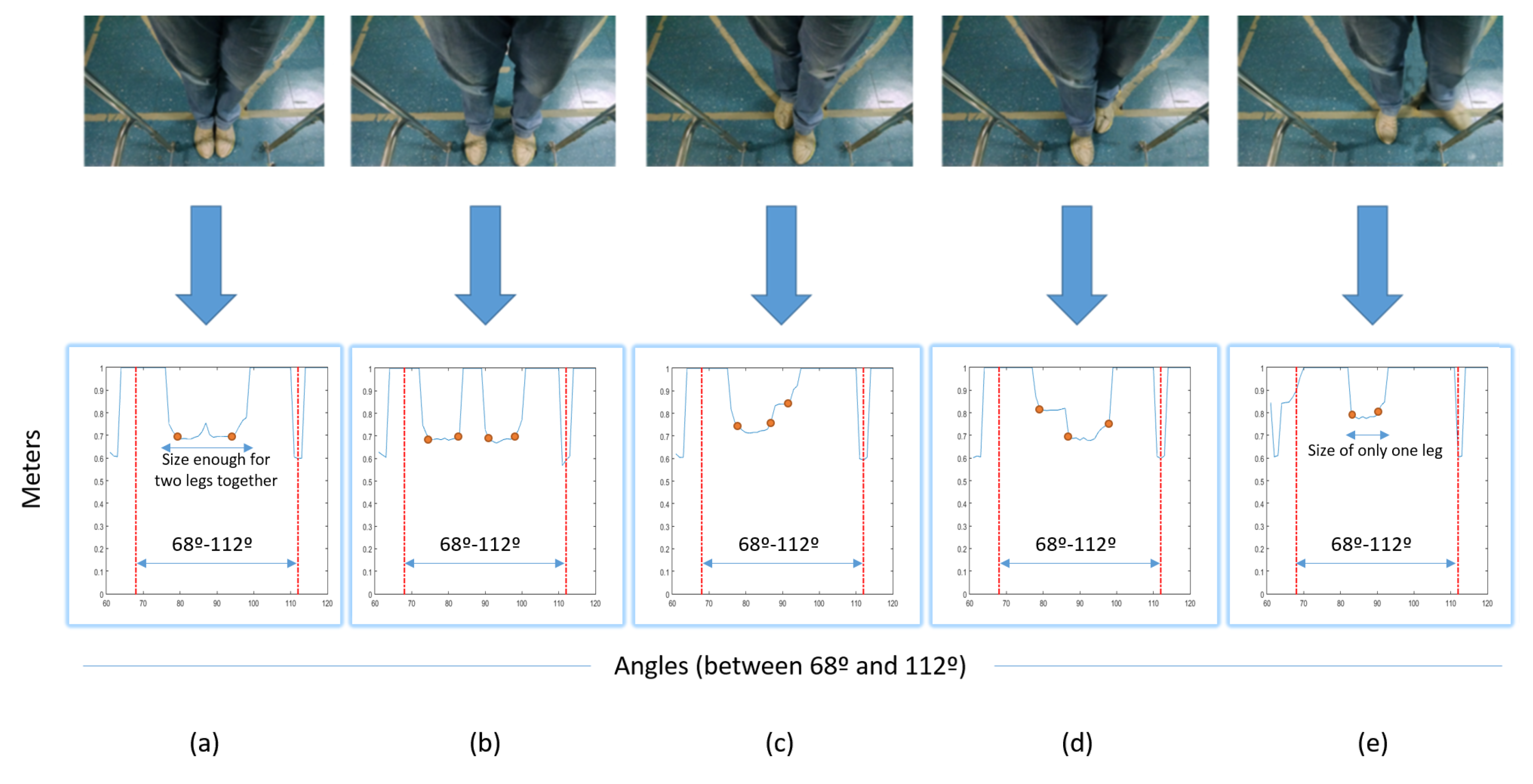
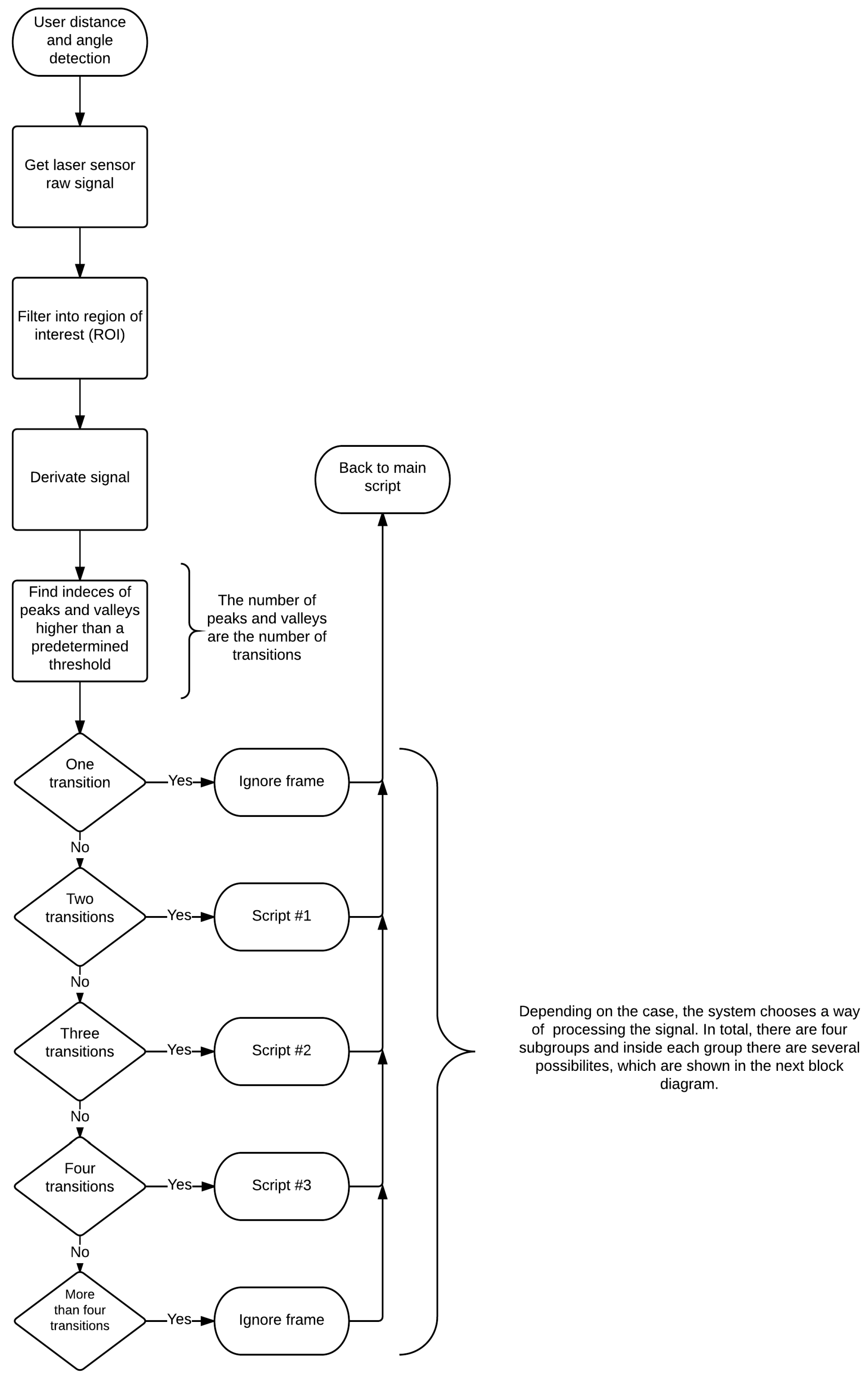
2.2.1. Legs and User Detection
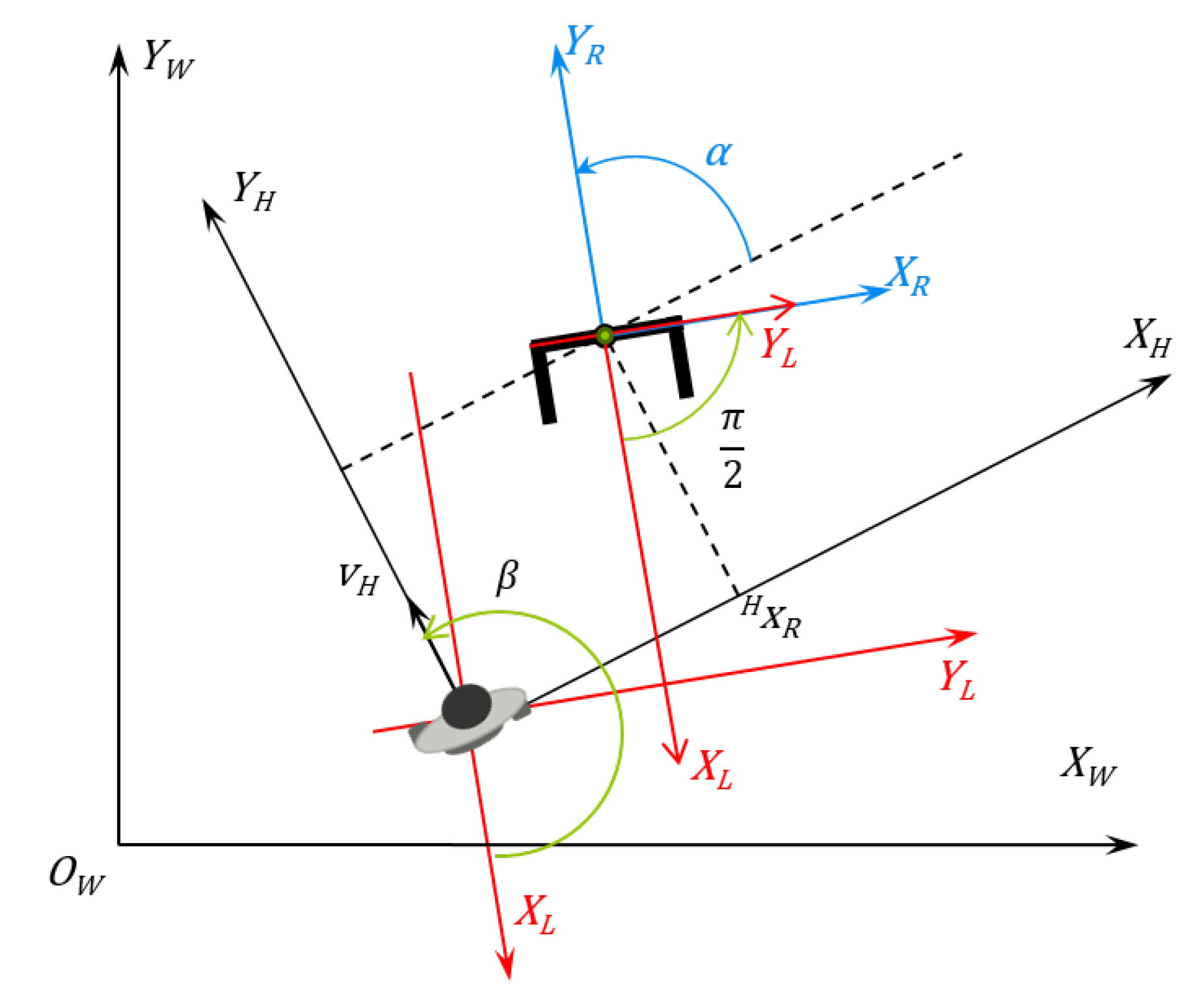
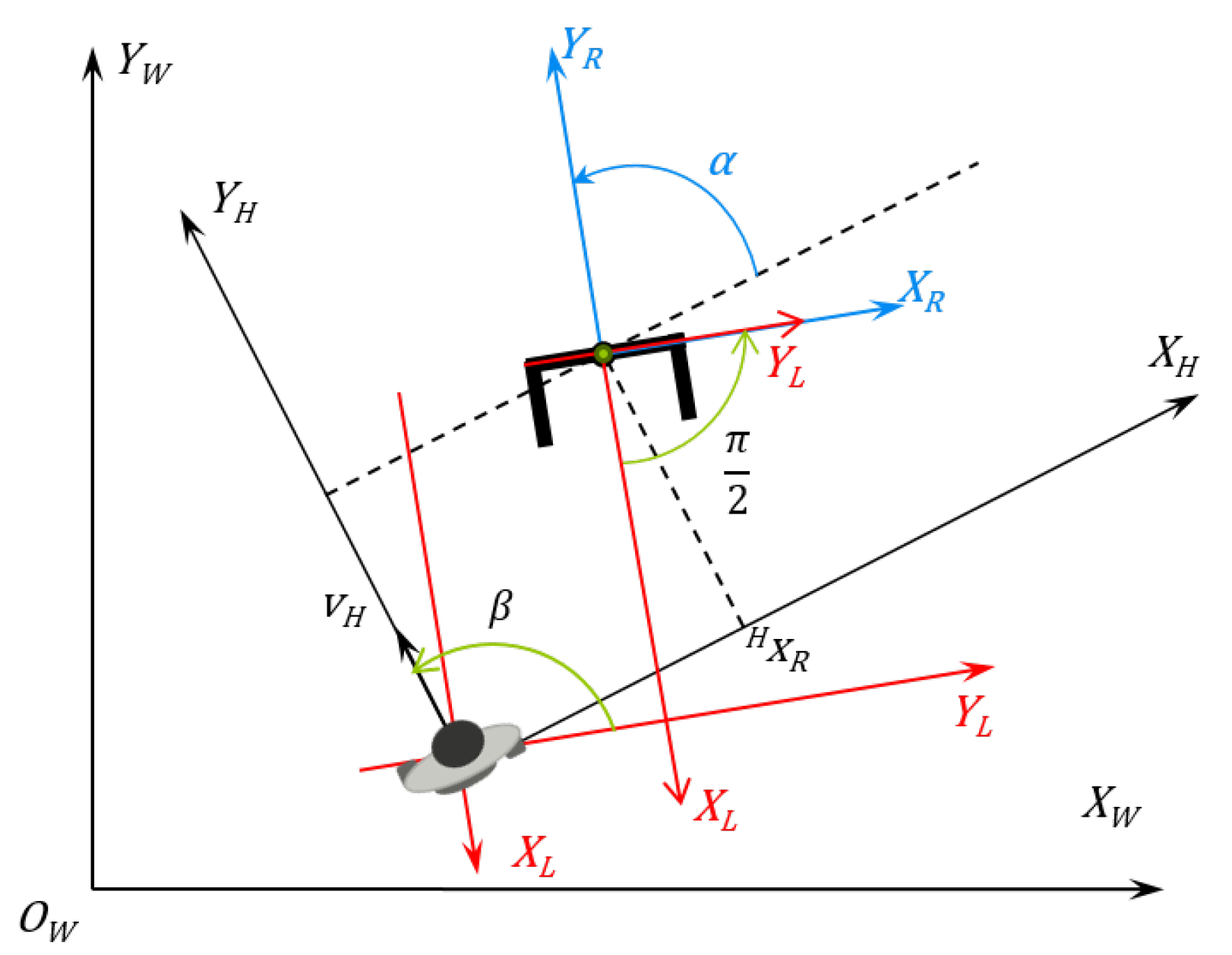
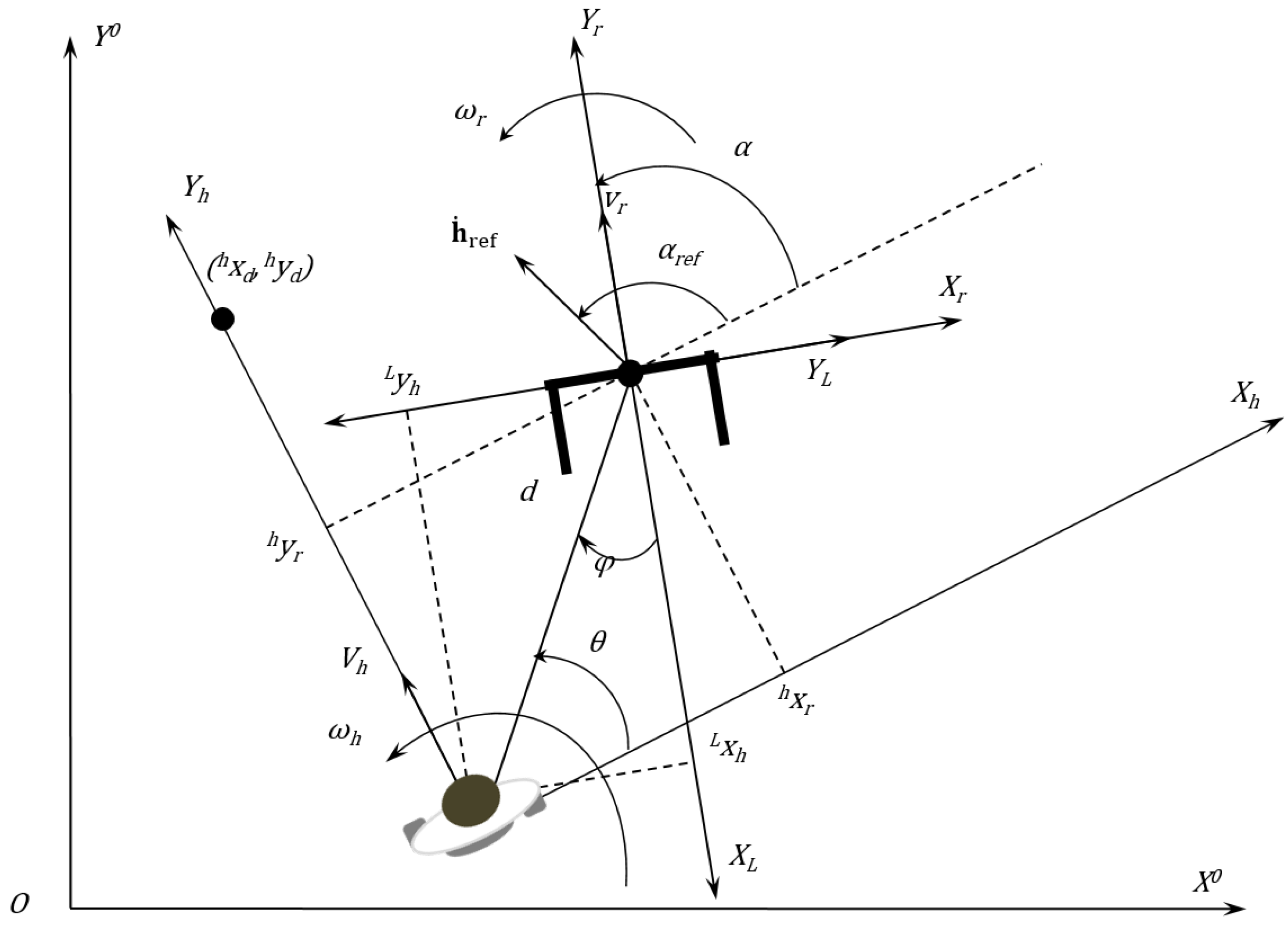
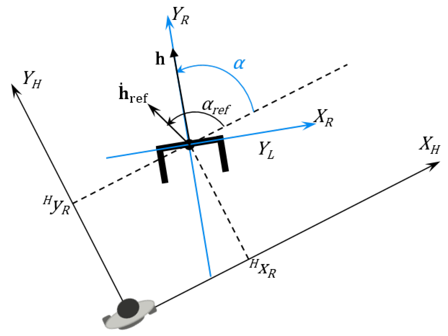
2.2.2. Human-Robot Kinematics
- First, the coordinates are calculated in the Cartesian system (Equation (14)).where , are the Cartesian coordinates with the laser sensor reference at the instant k. These coordinates are calculated using the distance and angle from the laser sensor ( and ).
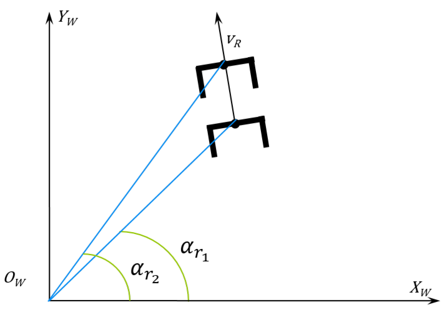
- Second, after computing the human coordinates in the laser reference, it is necessary to measure the human linear and angular speed. To this end, it is necessary to calculate the robot angle variation, which is given by Equation (15). Figure 10 depicts the absolute angle robot variation.where means the robot absolute angle, and is its variation in two consecutive instants.
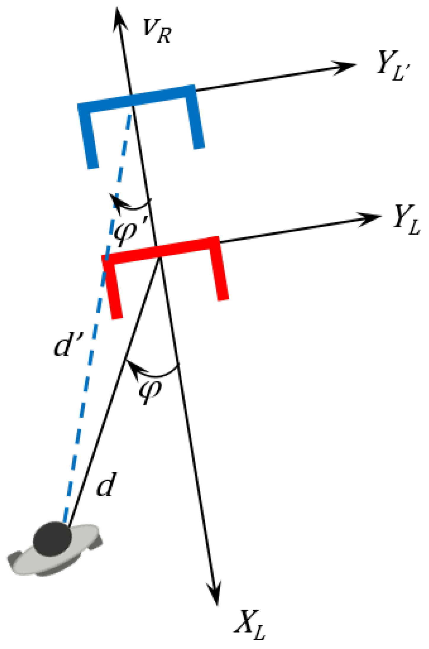
- Following the control algorithm, this variation is used to calculate the rotation and translation transform matrices used to find the human previous location projected in the current one (Figure 11).
- and are the human position in the laser reference at instant .
- and are the previous item position projected into the current instant k.
- is the robot linear speed.
- is the sample time between two consecutive instants of time (in the figure, the time needed for the walker to move from , which is supposed to be in the instant , to , which is supposed to be in instant k, which is the current instant.
- Subscript means the positions in instant projected into instant k.
- 4.
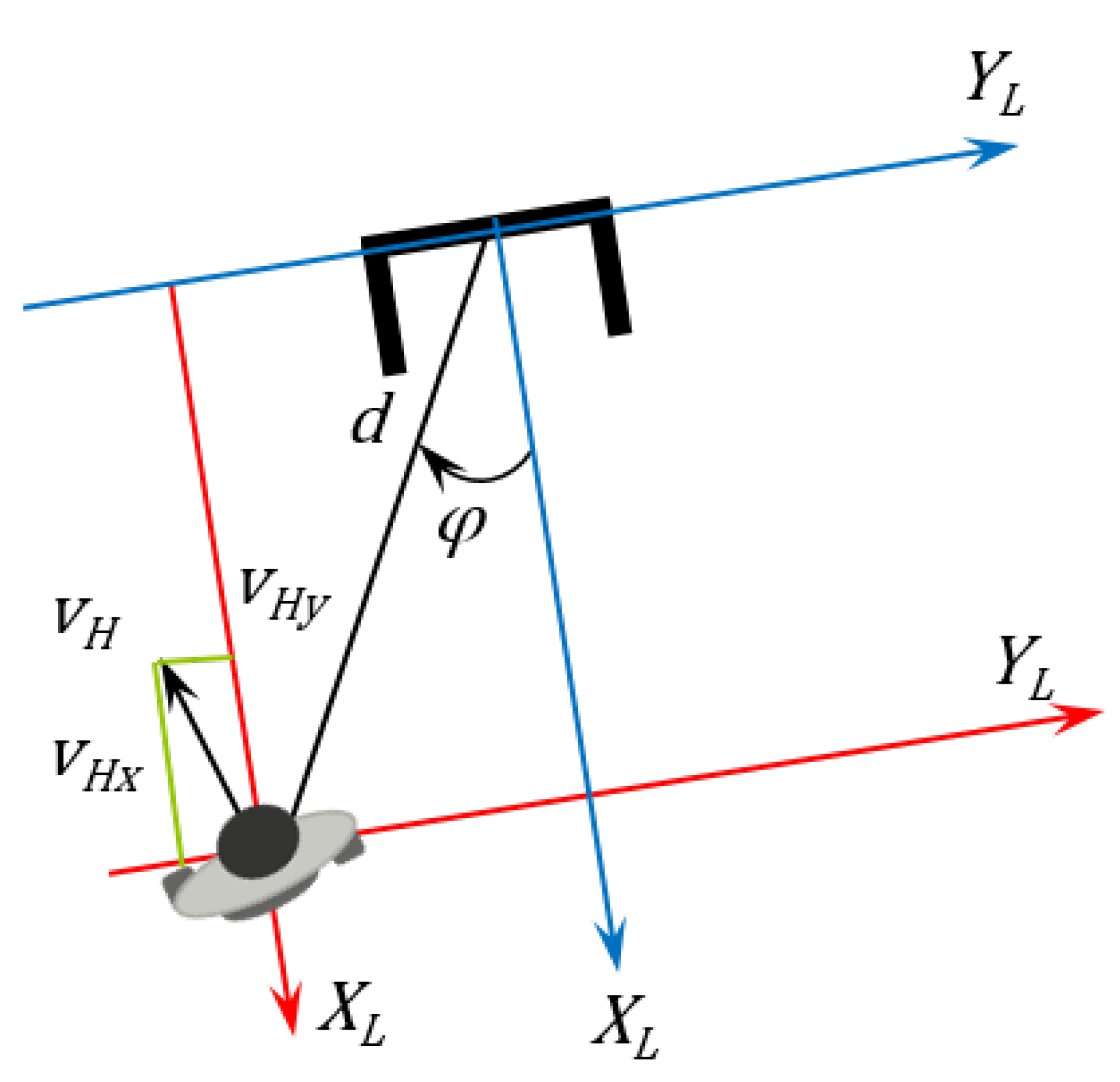
- Once the human’s previous location projected on the current robot reference and the current user location are available, it is possible to compute the human linear and angular speeds. The human speed in this case is the same for the robot reference and the absolute reference. This occurs because it is a variation, and the robot displacement in the absolute reference was taken into account in the last part of Equation (16).
- 5.
- The next step relies on computing the human orientation in the robot reference, as shown in Figure 13.
- 6.
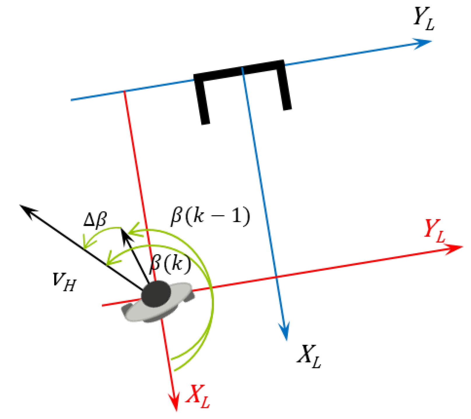
- Using the variation of the angle β, it is possible to find the human angular speed on the robot reference. The robot angular speed is previously provided by the robot encoders. Figure 14 shows how the angle variation affects the user angular speed.where and are the absolute speeds of the human and the robot.
- 7.
- 8.
- Following the calculation of the control actions, the next step is to find the displacement vector T, which converts the robot’s reference into the user’s reference.
- 9.
- 10.
- 11.
- It is also essential to determine which are the desired values, given by the vector, represented in Equation (26).where the variables with subscript d indicate the desired values, i.e., the set-points of the robot position vector and each one of its components.
- 12.
- The error vector is given by Equation (27).
- 13.
- 14.
- Finally, the control laws are computed, as described in Equations (30) and (31).where and are the controller outputs. Thus, these are reference speeds the controller sends to the robot.
2.2.3. Control Stability Proof
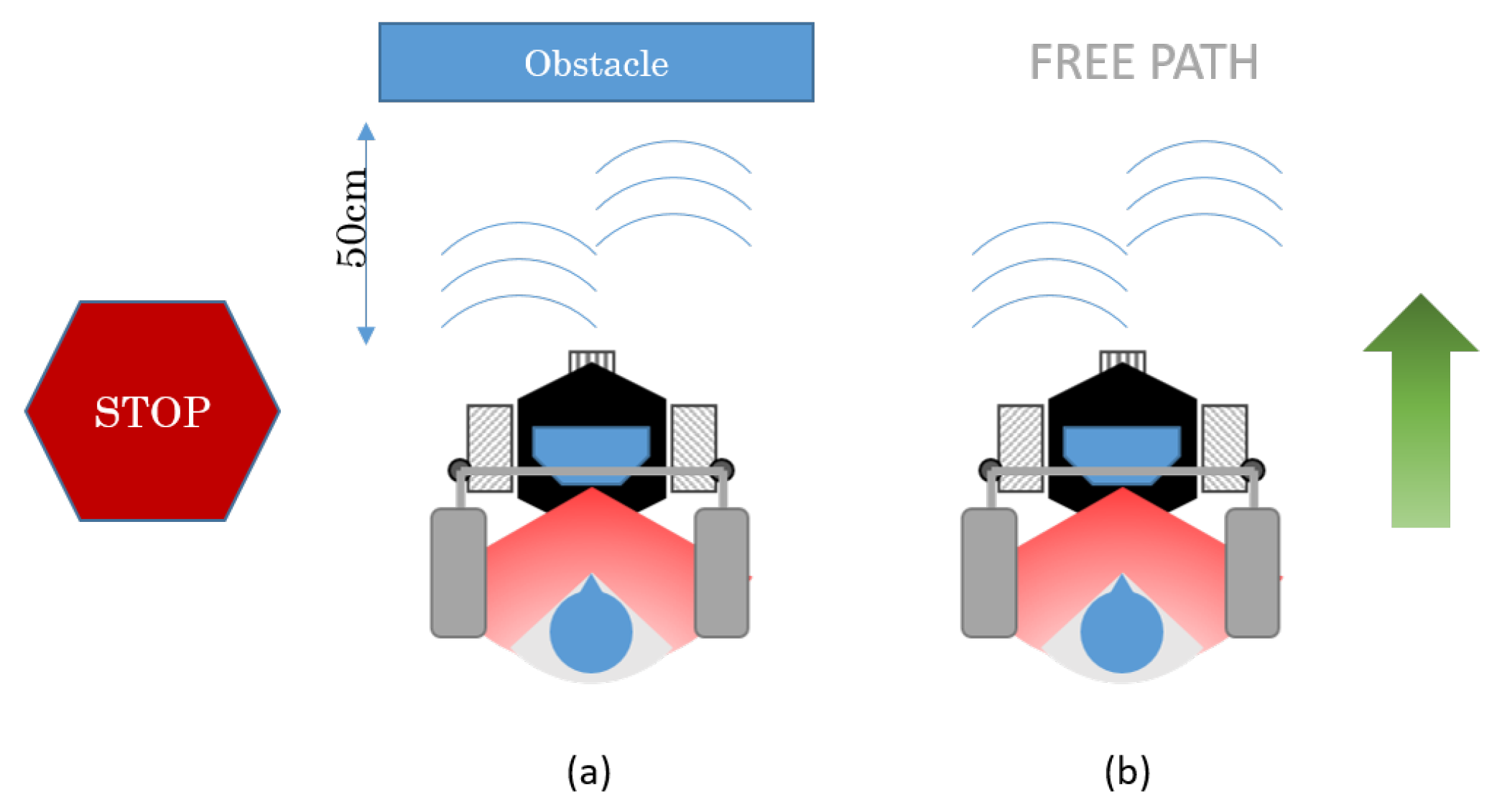
2.2.4. Safety Rules
3. Obstacle Avoidance
4. Experiments
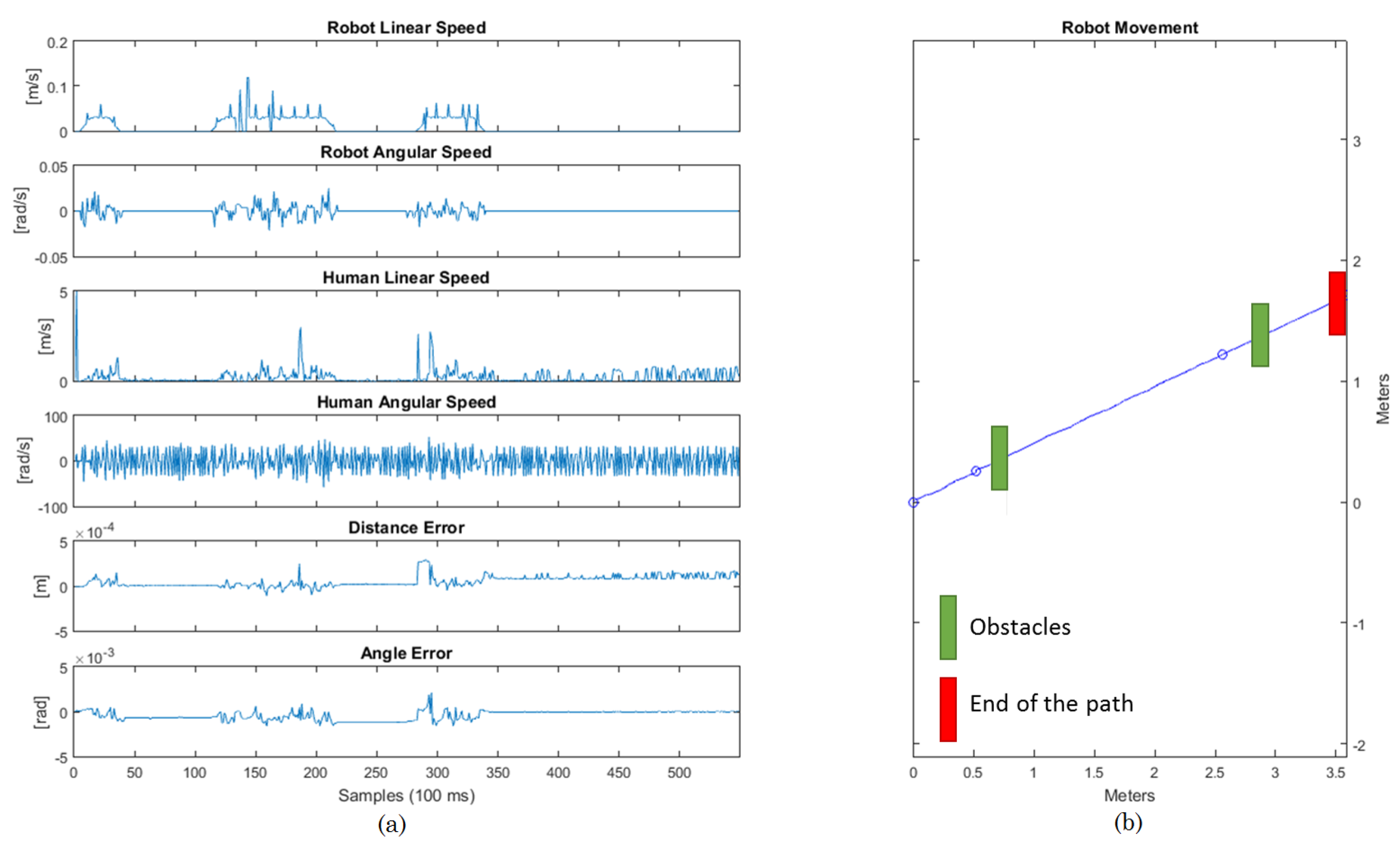
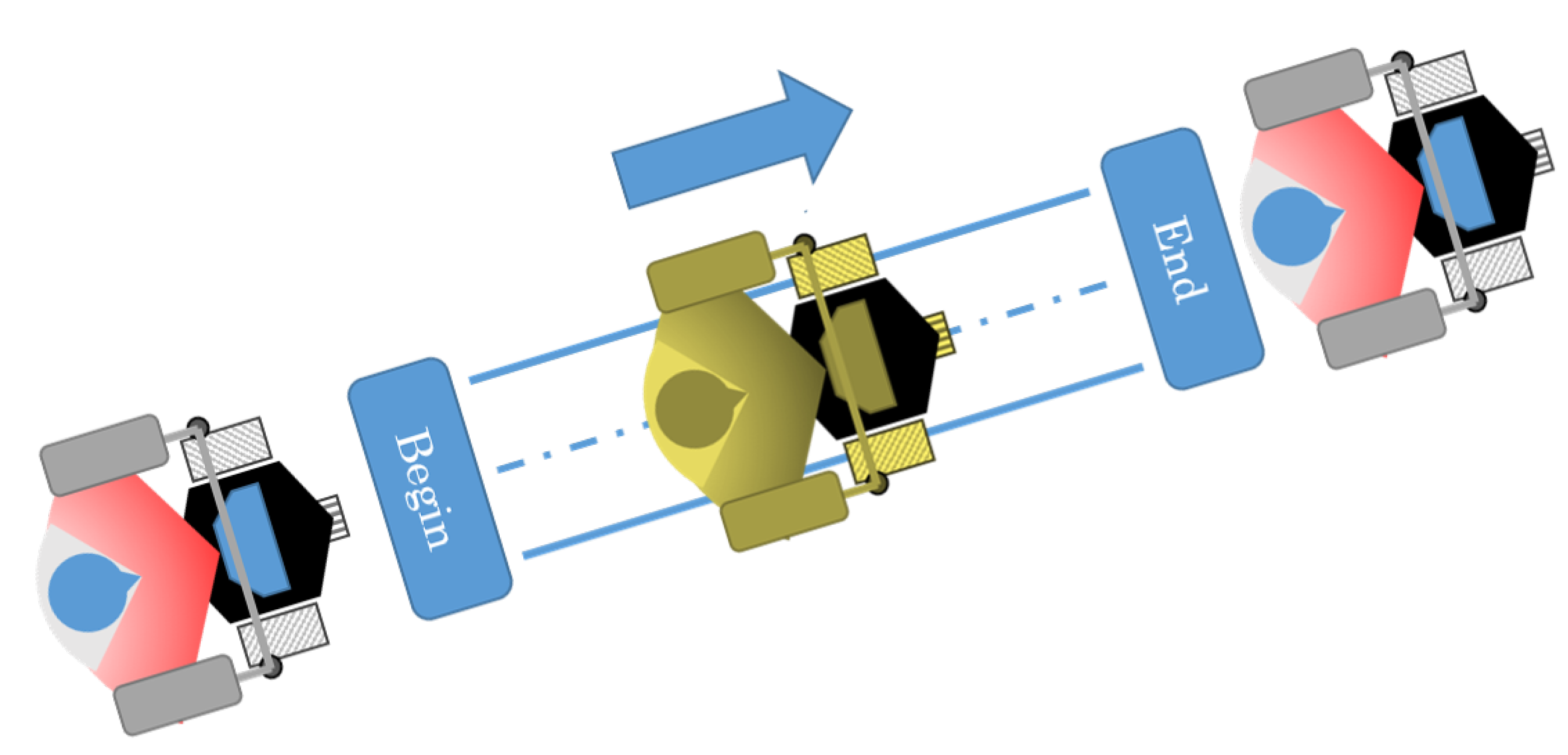
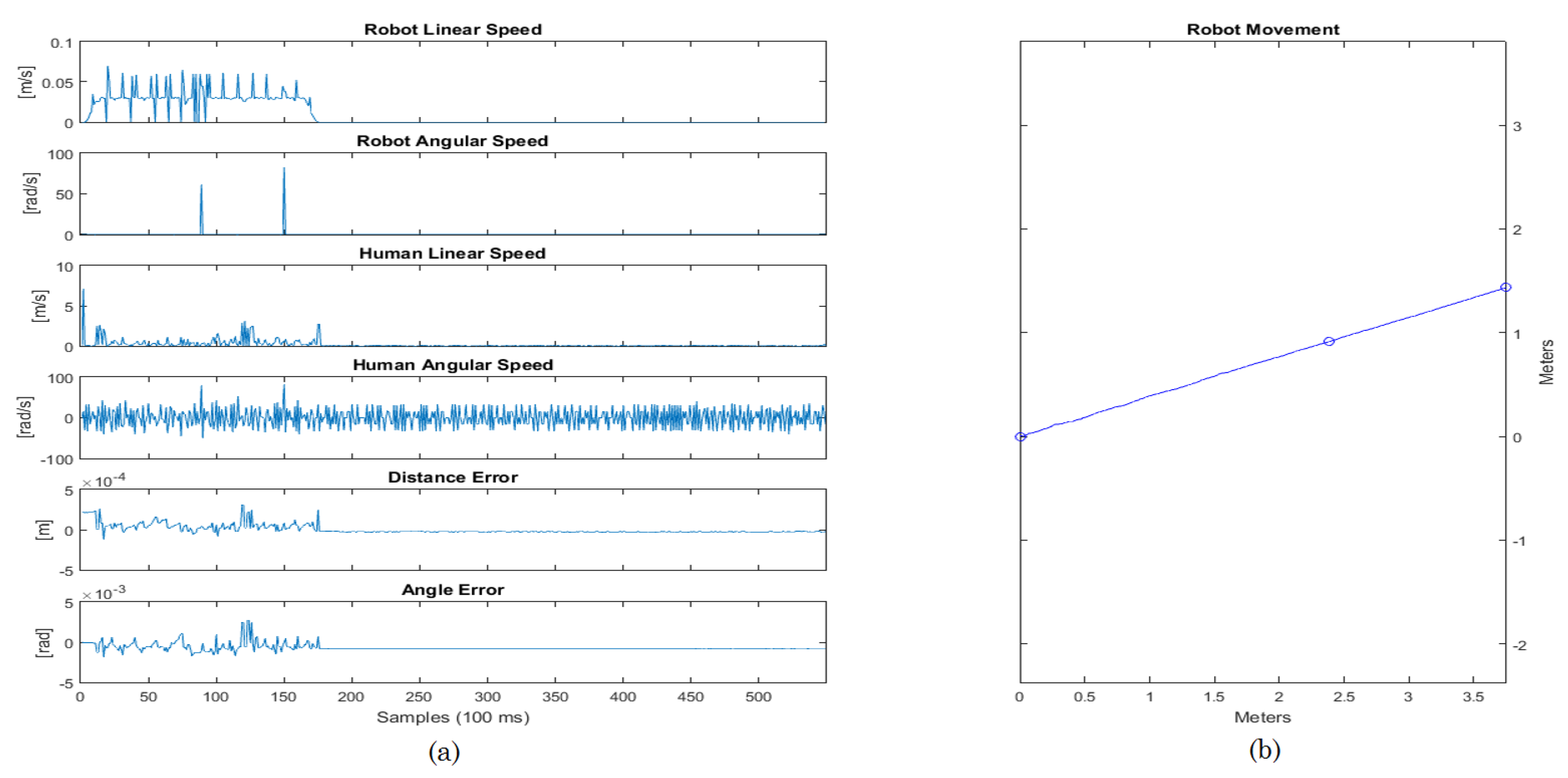
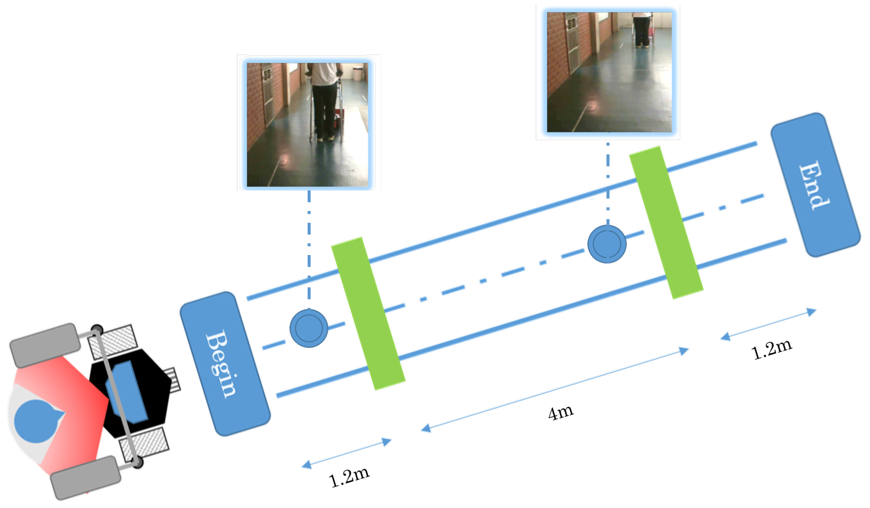
4.1. Straight Line
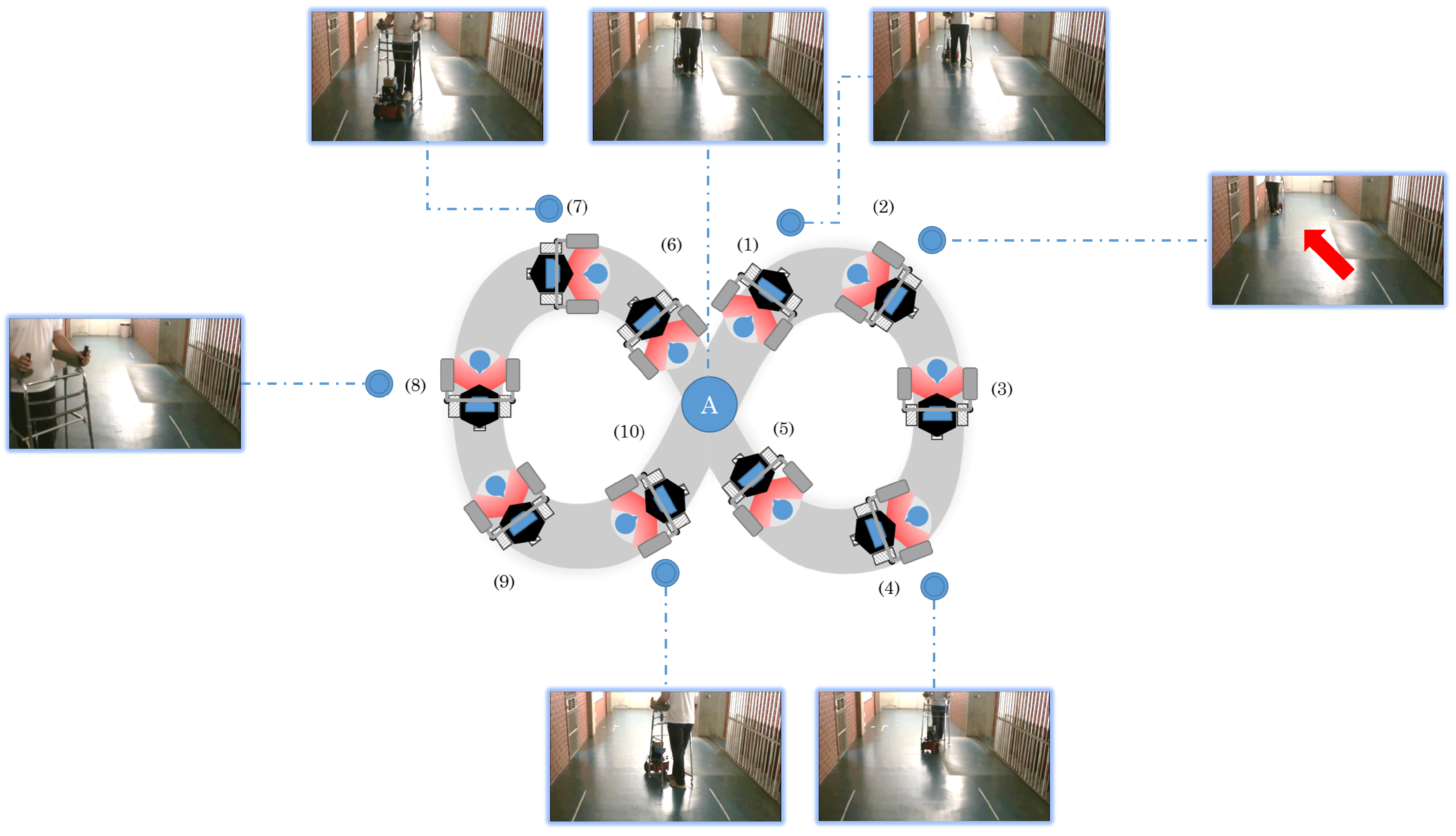
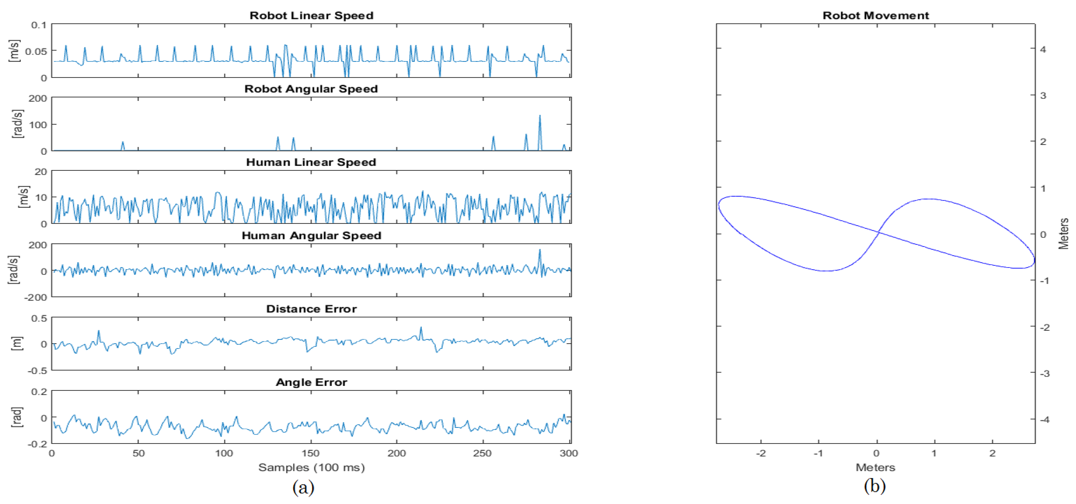
4.2. Lemniscate Path
5. Discussion
6. Conclusions
Acknowledgments
Author Contributions
Conflicts of Interest
Abbreviations
| LD | Leg detection |
| LMS | Laser measurement systems |
| LRF | Laser range finder |
| PID | Proportional-integral-derivative |
| ROI | Region of interest |
References
- Oxford Dictionaries. Available online: http://www.oxforddictionaries.com/definition/english/mobility (accessed on 10 May 2016).
- Yu, K.T.; Lam, C.P.; Chang, M.F.; Mou, W.H.; Tseng, S.H.; Fu, L.C. An interactive robotic walker for assisting elderly mobility in senior care unit. In Proceedings of the IEEE Workshop on Advanced Robotics and Its Social Impacts, ARSO, Seoul, Korea, 26–28 October 2010; pp. 24–29.
- Morris, A.; Donamukkala, R.; Anuj, K.; Aaron, S.; Matthews, T.J.; Dunbar-Jacob, J.; Thrun, S. A robotic walker that provides guidance. In Proceedings of the 2003 IEEE International Conference on Robotics and Automation (Cat. No. 03CH37422), Taipei, Taiwan, 14–19 September 2003; pp. 25–30.
- Valadão, C.; Cifuentes, C.; Frizera, A.; Carelli, R.; Bastos, T. Development of a Smart Walker to Assist Human Mobility. In Proceedings of the 4th IEEE Biosignals and Biorobotics conference (ISSNIP), Rio de Janeiro, Brazil, 18–20 February 2013; pp. 1–5.
- Cook, A.M.; Polgar, J.M. Cook and Hussey’s Assistive Technologies: Principles and Practice, 3rd ed.; Mosby Elsevier: St. Louis, MO, USA, 2013; p. 592. [Google Scholar]
- Duxbury, A.S. Gait Disorders and Fall Risk: Detection and Prevention. Comp. Ther. 2000, 26, 238–245. [Google Scholar] [CrossRef]
- Martins, M.M.; Santos, C.P.; Frizera-Neto, A.; Ceres, R. Assistive Mobility Devices Focusing on Smart Walkers: Classification and Review. Robot. Auton. Syst. 2012, 60, 548–562. [Google Scholar] [CrossRef] [Green Version]
- World Health Organization. WHO Global Report on Falls Prevention in Older Age; World Health Organization Press: Geneva, Switzerland, 2007; p. 53. [Google Scholar]
- Bradley, S.M.; Hernandez, C.R. Geriatric assistive devices. Am. Fam. Physician 2011, 84, 405–411. [Google Scholar] [PubMed]
- United Nations. World Population Ageing 1950–2050. In Technical Report 26; United Nations: New York, NY, USA, 2002; pp. xxvii–xxxi. [Google Scholar]
- Kamata, M.; Shino, M. Mobility devices for the elderly: “Silver vehicle” feasibility. IATSS Res. 2006, 30, 52–59. [Google Scholar] [CrossRef]
- Ceres, R.; Pons, J.; Calderon, L.; Jimenez, A.; Azevedo, L. A robotic vehicle for disabled children. IEEE Eng. Med. Biol. Mag. 2005, 24, 55–63. [Google Scholar] [CrossRef] [PubMed]
- Frizera Neto, A. Interfaz Multimodal Para Modelado y Asistencia a la Marcha Humana Mediante Andadores Robóticos. Ph.D. Thesis, Universidad de Alcalá, Madrid, Spain, 2010. [Google Scholar]
- Bastos-Filho, T.F.; Cheein, F.A.; Muller, S.M.T.; Celeste, W.C.; De La Cruz, C.; Cavalieri, D.C.; Sarcinelli-Filho, M.; Amaral, P.F.S.; Perez, E.; Soria, C.M.; et al. Towards a new modality-independent interface for a robotic wheelchair. IEEE Trans. Neural Syst. Rehabil. Eng. 2014, 22, 567–584. [Google Scholar] [CrossRef] [PubMed]
- Wasson, G.; Gunderson, J.; Graves, S.; Felder, R. An Assistive Robotic Agent for Pedestrian Mobility. In Proceedings of the 5th International Conference on Autonomous Agents, Montreal, QC, Canada, 28 May–1 June 2001; pp. 169–173.
- Alwan, M.; Wasson, G.; Sheth, P.; Ledoux, A.; Huang, C. Passive derivation of basic walker-assisted gait characteristics from measured forces and moments. In Proceedings of the Annual International Conference of the IEEE Engineering in Medicine and Biology Society, San Francisco, CA, USA, 1–5 September 2004.
- Wasson, G.; Sheth, P.; Alwan, M.; Granata, K.; Ledoux, A.; Huang, C. User Intent in a Shared Control Framework for Pedestrian Mobility Aids. In Proceedings of the 2003 IEEE/RSJ International Conference on Intelligent Robots and Systems, (IROS 2003), Las Vegas, NE, USA, 27–31 October 2003; pp. 2962–2967.
- Wasson, G.; Sheth, P.; Ledoux, A.; Alwan, M. A physics-based model for predicting user intent in shared-control pedestrian mobility aids. In Proceedings of the 2004 IEEE/RSJ International Conference on Intelligent Robots and Systems (IROS) (IEEE Cat. No. 04CH37566), Sendai, Japan, 28 September–2 October 2004; pp. 1914–1919.
- Loterio, F.A.; Mayor, J.J.V.; Frizera Neto, A.; Filho, T.F.B. Assessment of applicability of robotic walker for post-stroke hemiparetic individuals through muscle pattern analysis. In Proceedings of the 5th ISSNIP-IEEE Biosignals and Biorobotics Conference (2014): Biosignals and Robotics for Better and Safer Living (BRC), Salvador, Brazil, 26–28 May 2014; IEEE: Salvador, Brazil, 2014; pp. 1–5. [Google Scholar]
- Kikuchi, T.; Tanaka, T.; Tanida, S.; Kobayashi, K.; Mitobe, K. Basic study on gait rehabilitation system with intelligently controllable walker (i-Walker). In Proceedings of the 2010 IEEE International Conference on Robotics and Biomimetics, ROBIO 2010, Tianjin, China, 14–18 December 2010; pp. 277–282.
- Valadão, C.; Cifuentes, C.; Frizera, A.; Carelli, R.; Bastos, T. Development of a Smart Walker for People with Disabilities and Elderlies. In XV Reunión de Trabajo en Procesamiento de la Información y Control; RPIC: San Carlos de Bariloche, Argentina, 2013; pp. 977–982. [Google Scholar]
- Rodriguez, C.; Cifuentes, C.; Frizera, A.; Bastos, T. Metodologia para Obtenção de Comandos de Navegação de um Andador Robótico Através de Sensores de Força e Laser. In XI Simpósio Brasileiro de Automação Inteligente (SBAI), 2013; SBA: Fortaleza, Brazil, 2013; pp. 1–6. [Google Scholar]
- Lacey, G.; Mac Namara, S.; Dawson-Howe, K.M. Personal Adaptive Mobility Aid for the Infirm and Elderly Blind. In Assistive Technology and Artificial Intelligence; Springer: Berlin, Germany; Heidelberg, Germany, 1998; pp. 211–220. [Google Scholar]
- Figure-Pixabay. Available online: https://pixabay.com/ (accessed on 18 July 2016).
- Chan, A.D.C.; Green, J.R. Smart rollator prototype. In Proceedings of the MeMeA 2008—IEEE International Workshop on Medical Measurements and Applications, Ottawa, ON, Canada, 9–10 May 2008; pp. 97–100.
- Einbinder, E.; Horrom, T.A. Smart Walker: A tool for promoting mobility in elderly adults. J. Rehabil. Res. Dev. 2010, 47, xiii–xv. [Google Scholar] [CrossRef] [PubMed]
- Rodriguez-Losada, D.; Matia, F.; Jimenez, A.; Galan, R.; Lacey, G. Implementing map based navigation in guido, the robotic SmartWalker. In Proceedings of the 2005 IEEE International Conference on Robotics and Automation, Barcelona, Spain, 18–22 April 2005; pp. 3390–3395.
- Wachaja, A.; Agarwal, P.; Zink, M.; Adame, M.R.; Moller, K.; Burgard, W. Navigating blind people with a smart walker. In Proceedings of the 2015 IEEE/RSJ International Conference on Intelligent Robots and Systems (IROS), Hamburg, Germany, 28 September–3 October 2015; pp. 6014–6019.
- Rodriguez-Losada, D. A Smart Walker for the Blind. Robot. Autom. Mag. 2008, 15, 75–83. [Google Scholar]
- Kulyukin, V.; Kutiyanawala, A.; LoPresti, E.; Matthews, J.; Simpson, R. iWalker: Toward a rollator-mounted wayfinding system for the elderly. In Proceedings of the 2008 IEEE International Conference on RFID, Las Vegas, NV, USA, 16–17 April 2008; pp. 303–311.
- Hirata, Y.; Muraki, A.; Kosuge, K. Motion control of intelligent passive-type walker for fall-prevention function based on estimation of user state. In Proceedings of the 2006 IEEE International Conference on Robotics and Automation, Orlando, FL, USA, 15–19 May 2006; pp. 3498–3503.
- Lacey, G.; Dawson-Howe, K. Evaluation of robot mobility aid for the elderly blind. In Proceedings of the Fifth International Symposium on Intelligent Robotic Systems, Stockholm, Sweden, 8–11 July 1997.
- Rentschler, A.J.; Simpson, R.; Cooper, R.A.; Boninger, M.L. Clinical evaluation of Guido robotic walker Andrew. J. Rehabil. Res. Dev. 2008, 45, 1281. [Google Scholar] [CrossRef] [PubMed]
- Lee, G.; Ohnuma, T.; Chong, N.Y. Design and control of JAIST active robotic walker. Intell. Serv. Robot. 2010, 3, 125–135. [Google Scholar] [CrossRef]
- Frizera-Neto, A.; Ceres, R.; Rocon, E.; Pons, J.L. Empowering and assisting natural human mobility: The simbiosis walker. Int. J. Adv. Robot. Syst. 2011, 8, 34–50. [Google Scholar]
- Dubowsky, S.; Genot, F.; Godding, S.; Kozono, H.; Skwersky, A.; Yu, H.; Yu, L.S. PAMM—A robotic aid to the elderly for mobility assistance and monitoring: A “helping-hand” for the elderly. In Proceedings of the IEEE International Conference on Robotics and Automation, San Francisco, CA, USA, 24–28 April 2000; pp. 570–576.
- Hirata, Y.; Hara, A.; Kosuge, K. Passive-type intelligent walking support system “RT Walker”. In Proceedings of the 2004 IEEE/RSJ International Conference on Intelligent Robots and Systems, Sendai, Japan, 28 September–2 October 2004; pp. 3871–3876.
- MacNamara, S.; Lacey, G. A smart walker for the frail visually impaired. In Proceedings of the IEEE International Conference on Robotics and Automation, San Francisco, CA, USA, 24–28 April 2000; pp. 1354–1359.
- Valadão, C.T.; Lotério, F.; Cardoso, V.; Bastos-Filho, T.; Frizera-Neto, A.; Carelli, R. Adaptação De Andador Convencional Para Reabilitação E Assistência a Pessoas Com Restrições Motoras. In XXIV Congresso Brasileiro de Engenharia Biomédica; SBEB: Uberlândia, Brazil, 2014; pp. 533–536. [Google Scholar]
- Sick. Technical Documentation LMS200/211/221/291 Laser Measurement Systems; 2006. Available online: http://sicktoolbox.sourceforge.net/docs/sick-lms-technical-description.pdf (accessed on 18 July 2016).
- Roberti, F.; Marcos Toibero, J.; Frizera Vassallo, R.; Carelli, R. Control Estable de Formación Basado en Visión Omnidireccional para Robots Móviles No Holonómicos. In Revista Iberoamericana de Automática e Informática Industrial RIAI; Elsevier: Madrid, Spain, 2011; pp. 29–37. [Google Scholar]
- Schneider Junior, V.; Frizera Neto, A.; Valadão, C.; Elias, A.; Bastos Filho, T.; Filho, A. Detecção de pernas utilizando um sensor de v. In Congresso Brasileiro de Automática; Universidade Federal do Espírito Santo: Vitória-ES, Brazil, 2012; pp. 1364–1370. [Google Scholar]


| Smart Walker | Sensors | Controllers |
|---|---|---|
| RT Walker [37] | Force/moment sensing and encoders | Several algorithm controllers for motion (obstacle avoidance, path following, among others) |
| GUIDO Smart Walker [29] | Laser sensor, force sensors, switches, sonar and encoders | Shared control approach |
| PAM-AID [38] | Ultrasound and laser sensors | Algorithmic controller |
| PAMM [36] | Health sensors, external sensors, encoders, force sensors, among others | Admittance-based controller |
| JARoW [34] | Infrared sensors | Algorithmic controllers |
| iWalker [30] | RFID, encoders and external sensors | Algorithmic controllers |
| UFES’ Smart Walker [22] | IMUs, laser sensor and force sensor | Force and inverse kinematics controllers |
| Our device | Laser sensor, encoders and ultrasound | Formation-based controller |
| Variable | Details | Unit |
|---|---|---|
| Human linear speed in the absolute axis | m/s | |
| Human angular speed in the absolute axis | rad/s | |
| d | Human-robot distance | m |
| θ | Robot angle in the human reference | rad |
| φ | Human angle in the robot reference | rad |
| and | Laser sensor longitudinal and transversal axis | m |
| and | Human longitudinal and transversal axis | m |
| and | Robot longitudinal and transversal axis | m |
| and | Human position in the laser sensor reference | m |
| and | Human position in the robot reference | m |
| and | Robot position in the human reference | m |
| Speed vector the robot should follow to keep the formation | m/s | |
| α | Robot orientation in the human reference | rad |
| Set-point orientation the robot should achieve to keep the formation | rad | |
| Robot linear speed | m/s | |
| Robot angular speed | m/s | |
| β | Human orientation in the robot reference | rad |
| Human linear speed in the transversal axis | m/s | |
| Human linear speed in the longitudinal axis | m/s | |
| k | Sample time | 0.1 s (100 ms) |
| Previous sample time | 0.1 s (100 ms) | |
| Positions and angles of instant () projected into instant (k) | 0.1 s (100 ms) |
| Situation | Action | Notes |
|---|---|---|
| No legs/only one leg detected, several times sequentially | Increase the counter | There is a counter that increases each time both legs are not detected. If this counter reaches the limit number, the walker stops immediately. The limit number can be defined inside the code. If the leg is detected before the counter reaches the limit, the counter is zeroed. |
| Counter exceeded limit | Brake the robot | If the counter reaches the maximum limit, it brakes the robot and stops its movement. |
| High speed | Limit speed | This safety rule is applicable for both linear and angular speeds. |
| Backwards movement | Brake the robot | Braking the robot in this case means the speed will be set up to zero. |
| Obstacle (detected by ultrasound sensors) | Brake the robot | The robot is stopped while the obstacle is not removed from the path. |
© 2016 by the authors; licensee MDPI, Basel, Switzerland. This article is an open access article distributed under the terms and conditions of the Creative Commons Attribution (CC-BY) license (http://creativecommons.org/licenses/by/4.0/).
Share and Cite
Valadão, C.; Caldeira, E.; Bastos-Filho, T.; Frizera-Neto, A.; Carelli, R. A New Controller for a Smart Walker Based on Human-Robot Formation. Sensors 2016, 16, 1116. https://doi.org/10.3390/s16071116
Valadão C, Caldeira E, Bastos-Filho T, Frizera-Neto A, Carelli R. A New Controller for a Smart Walker Based on Human-Robot Formation. Sensors. 2016; 16(7):1116. https://doi.org/10.3390/s16071116
Chicago/Turabian StyleValadão, Carlos, Eliete Caldeira, Teodiano Bastos-Filho, Anselmo Frizera-Neto, and Ricardo Carelli. 2016. "A New Controller for a Smart Walker Based on Human-Robot Formation" Sensors 16, no. 7: 1116. https://doi.org/10.3390/s16071116