Flexible Piezoelectric Energy Harvesting from Mouse Click Motions


Abstract
:1. Introduction
2. Modeling
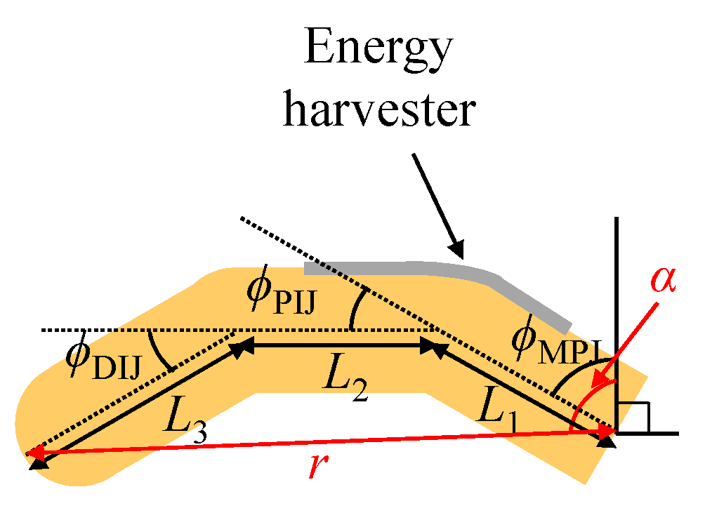
2.1. Finger Model
2.2. Energy Harvesting Model
3. Experiments
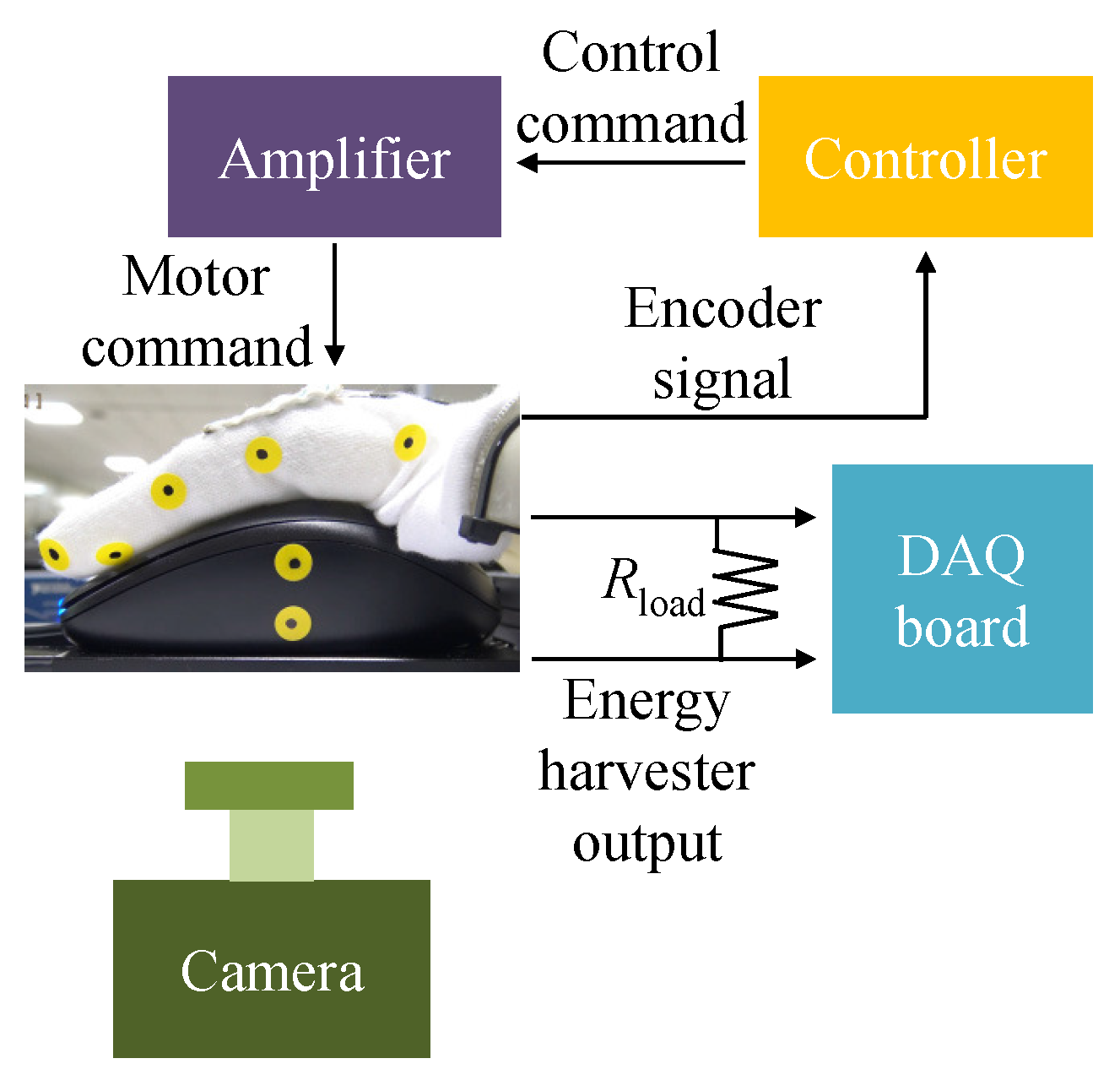
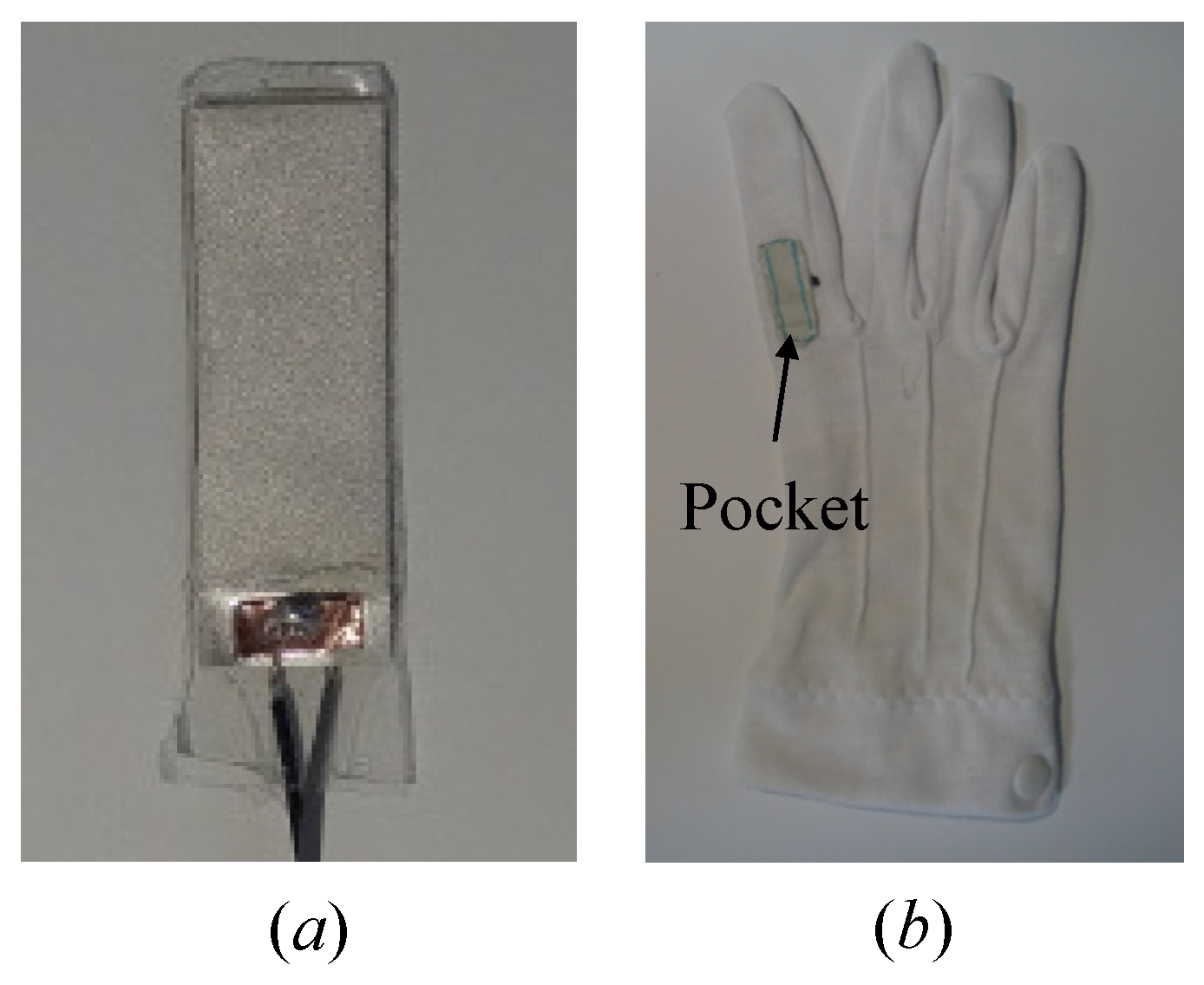
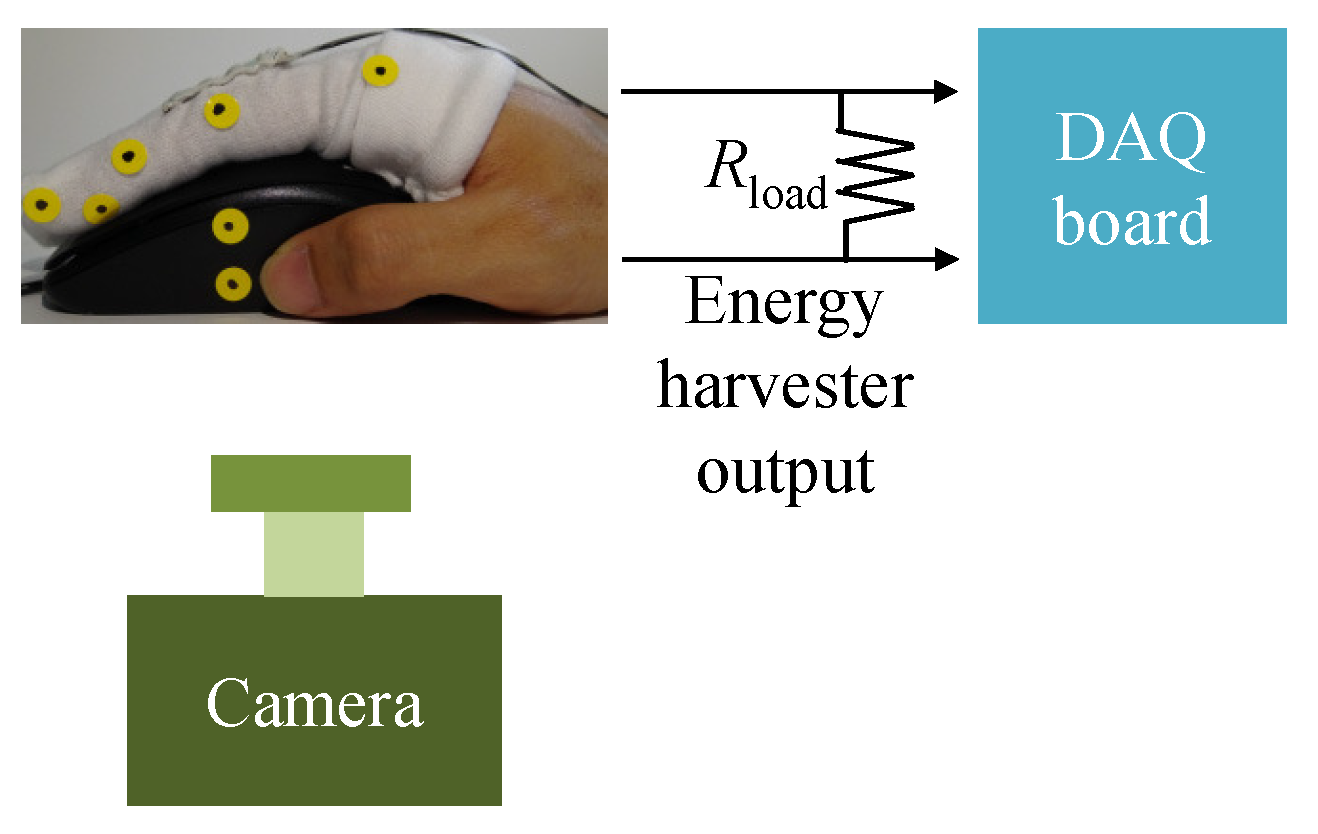
3.1. Experimental Setup
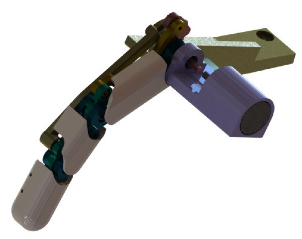
3.2. Robot Finger
4. Results
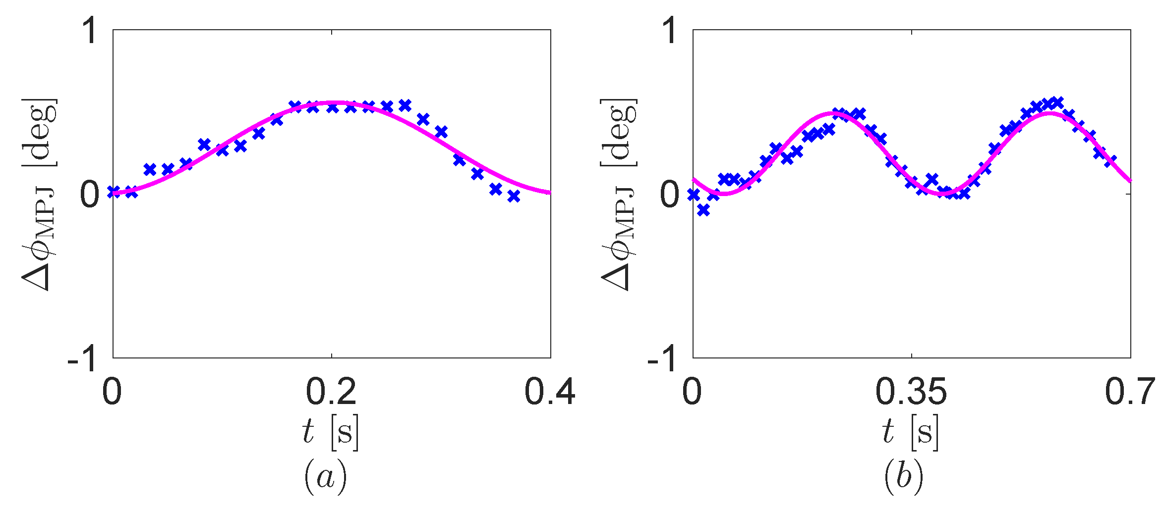
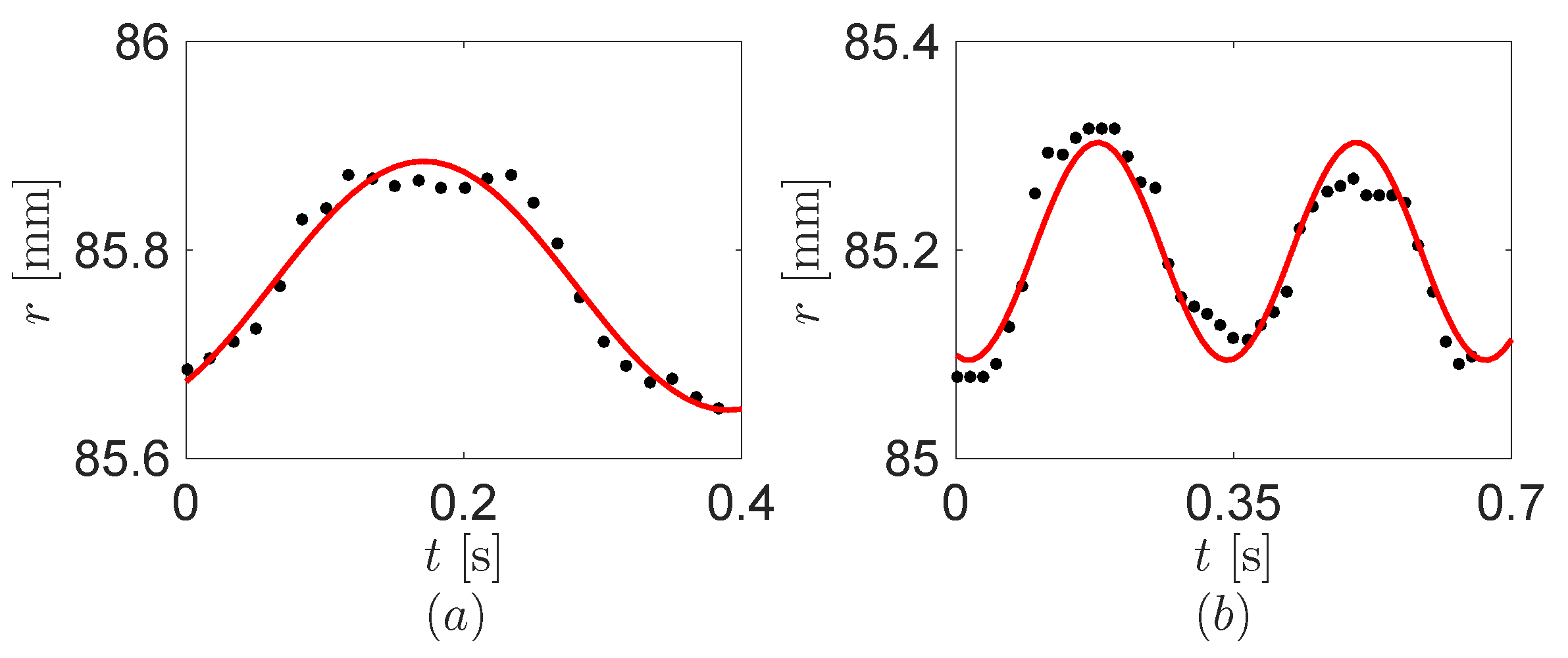
4.1. Motion Trajectory of Human Finger
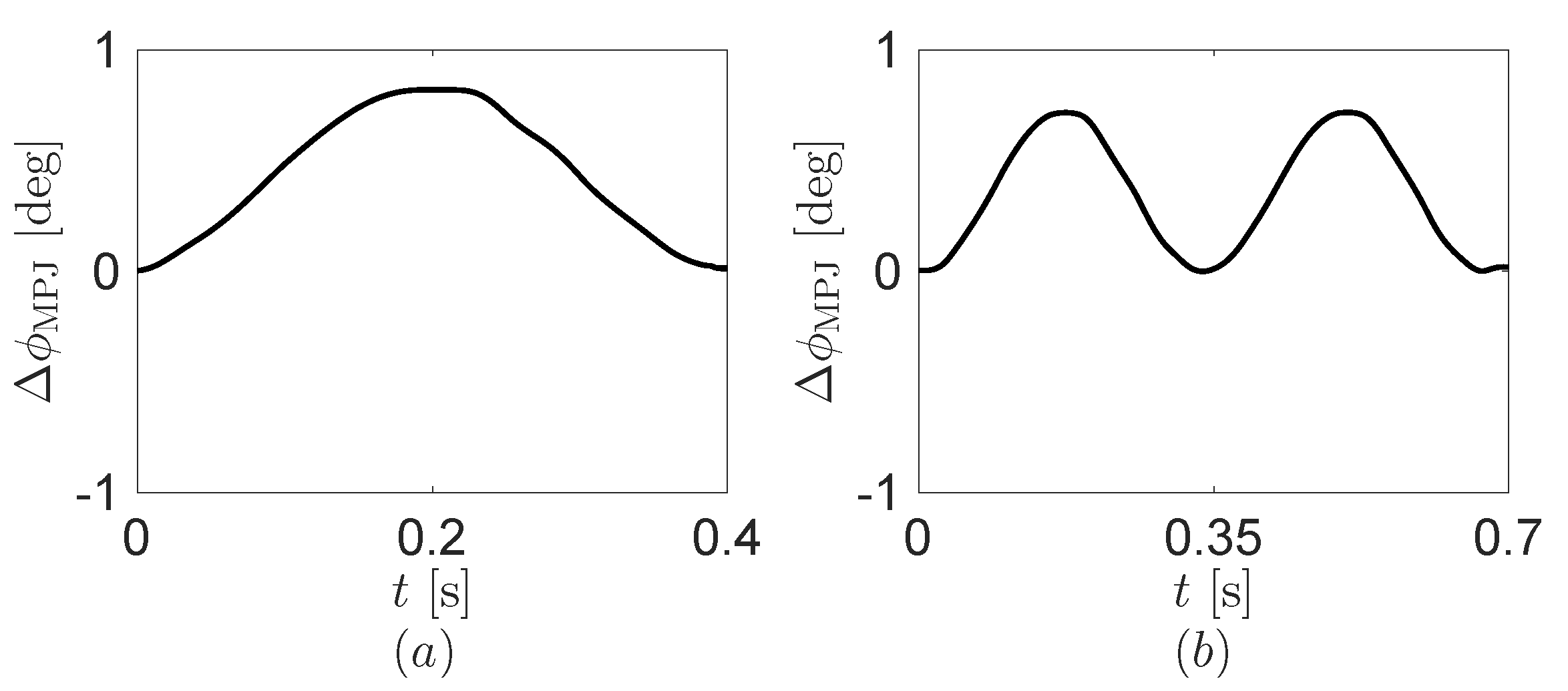
4.2. Operation of Robot Finger
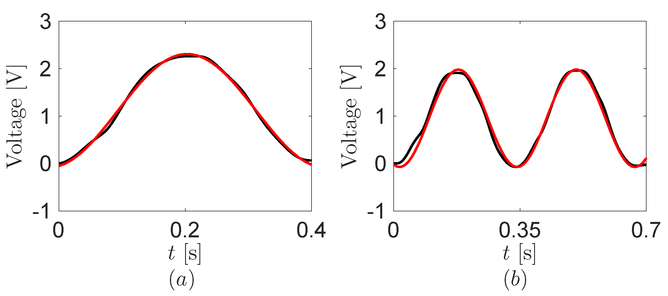
4.3. Open-Circuit Voltage from Robot Finger
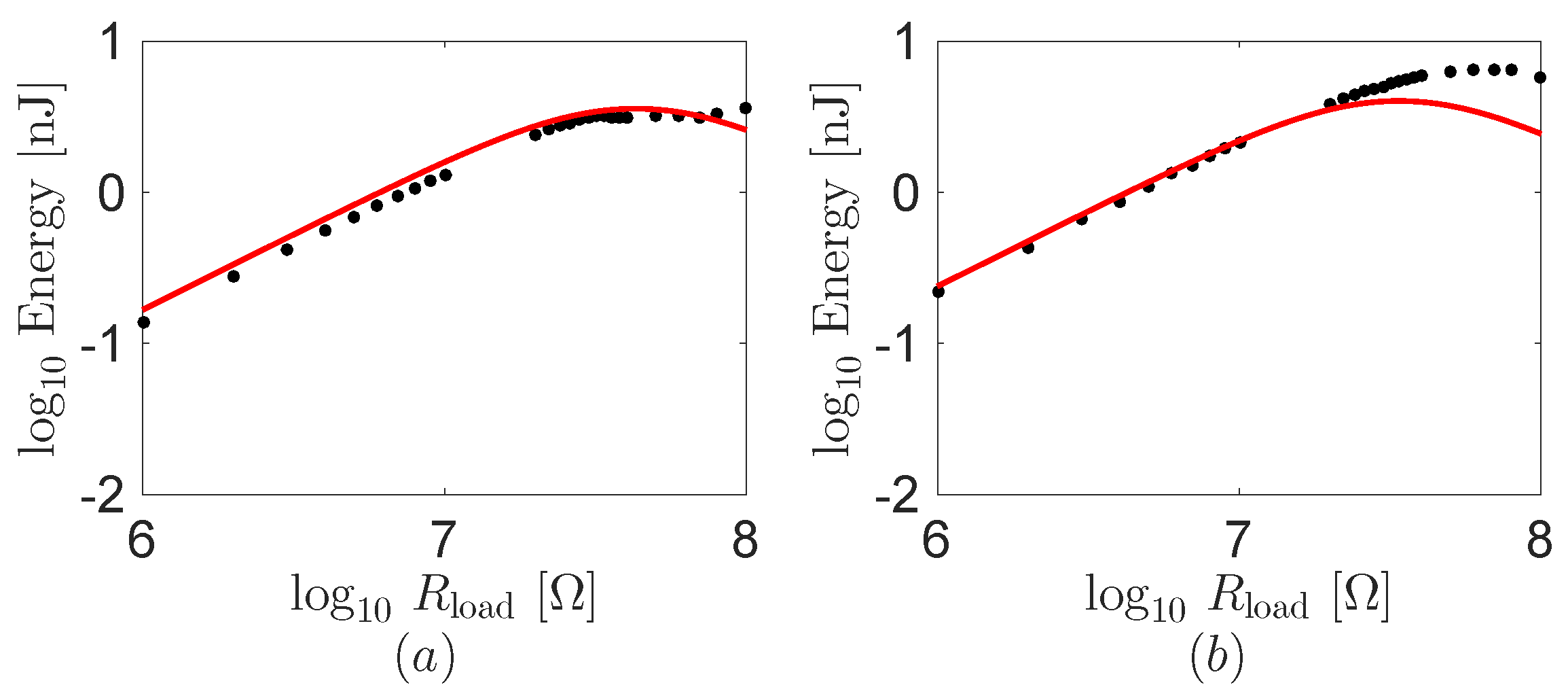
4.4. Energy Harvested from Robot Finger
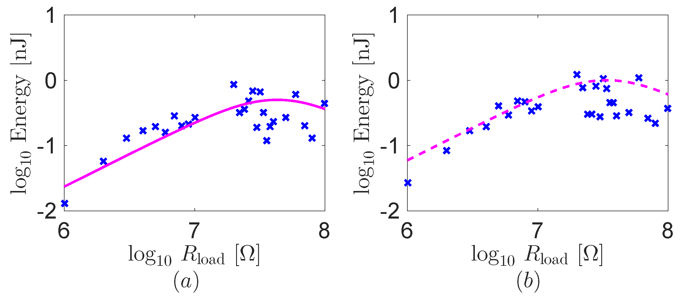
4.5. Energy Harvested from Human Finger
5. Conclusions
Acknowledgments
Author Contributions
Conflicts of Interest
References
- Stoppa, M.; Chiolerio, A. Wearable electronics and smart textiles: A critical review. Sensors 2014, 14, 11957–11992. [Google Scholar] [CrossRef] [PubMed]
- Zeng, W.; Shu, L.; Li, Q.; Chen, S.; Wang, F.; Tao, X.M. Fiber-based wearable electronics: A review of materials, fabrication, devices, and applications. Adv. Mater. 2014, 26, 5310–5336. [Google Scholar] [CrossRef] [PubMed]
- Bahk, J.H.; Fang, H.; Yazawa, K.; Shakouri, A. Flexible thermoelectric materials and device optimization for wearable energy harvesting. J. Mater. Chem. C 2015, 3, 10362–10374. [Google Scholar] [CrossRef]
- Kim, M.K.; Kim, M.S.; Lee, S.; Kim, C.; Kim, Y.J. Wearable thermoelectric generator for harvesting human body heat energy. Smart Mater. Struct. 2014, 23, 105002. [Google Scholar] [CrossRef]
- Kymissis, J.; Kendall, C.; Paradiso, J.; Gershenfeld, N. Parasitic power harvesting in shoes. In Proceedings of the 2nd IEEE International Symposium on Wearable Computers, Pittsburgh, PA, USA, 19–20 October 1998; pp. 132–139.
- Renaud, M.; Fiorini, P.; van Schaijk, R.; van Hoof, C. Harvesting energy from the motion of human limbs: The design and analysis of an impact-based piezoelectric generator. Smart Mater. Struct. 2009, 18, 035001. [Google Scholar] [CrossRef]
- Delnavaz, A.; Voix, J. Flexible piezoelectric energy harvesting from jaw movements. Smart Mater. Struct. 2014, 23, 105020. [Google Scholar] [CrossRef]
- Sodano, H.A.; Inman, D.J.; Park, G. Comparison of piezoelectric energy harvesting devices for recharging batteries. J. Intell. Mater. Syst. Struct. 2005, 16, 799–807. [Google Scholar] [CrossRef]
- Erturk, A.; Inman, D.J. Piezoelectric Energy Harvesting; John Wiley & Sons, Inc.: Chichester, West Sussex, UK, 2011. [Google Scholar]
- Elvin, N.; Erturk, A. (Eds.) Advances in Energy Harvesting Methods; Springer-Verlag: London, UK, 2013.
- Erturk, A.; Inman, D.J. An experimentally validated bimorph cantilever model for piezoelectric energy harvesting from base excitations. Smart Mater. Struct. 2009, 18, 025009. [Google Scholar] [CrossRef]
- Shahab, S.; Gray, M.; Erturk, A. Ultrasonic power transfer from a spherical acoustic wave source to a free-free piezoelectric receiver: Modeling and experiment. J. Appl. Phys. 2015, 117, 104903. [Google Scholar] [CrossRef]
- Panciroli, R.; Porfiri, M. Hydroelastic impact of piezoelectric structures. Int. J. Impact Eng. 2014, 66, 18–27. [Google Scholar] [CrossRef]
- Vatansever, D.; Hadimani, R.L.; Shah, T.; Siores, E. An investigation of energy harvesting from renewable sources with PVDF and PZT. Smart Mater. Struct. 2011, 20, 055019. [Google Scholar] [CrossRef]
- Jiang, Y.; Shiono, S.; Hamada, H.; Fujita, T.; Higuchi, K.; Maenaka, K. Low-frequency energy harvesting using a laminated PVDF cantilever with a magnetic mass. Power MEMS 2010, 2010, 375378. [Google Scholar]
- Akaydin, H.D.; Elvin, N.; Andreopoulos, Y. Energy harvesting from highly unsteady fluid flows using piezoelectric materials. J. Intell. Mater. Syst. Struct. 2010, 21, 1263–1278. [Google Scholar] [CrossRef]
- Zizys, D.; Gaidys, R.; Dauksevicius, R.; Ostasevicius, V.; Daniulaitis, V. Segmentation of a vibro-shock cantilever-type piezoelectric energy harvester operating in higher transverse vibration modes. Sensors 2015, 15. [Google Scholar] [CrossRef] [PubMed] [Green Version]
- Yang, Y.; Tang, L.; Li, H. Vibration energy harvesting using macro-fiber composites. Smart Mater. Struct. 2009, 18, 115025. [Google Scholar] [CrossRef]
- Erturk, A.; Delporte, G. Underwater thrust and power generation using flexible piezoelectric composites: An experimental investigation toward self-powered swimmer-sensor platforms. Smart Mater. Struct. 2011, 20, 125013. [Google Scholar] [CrossRef]
- Cha, Y.; Kim, H.; Porfiri, M. Energy harvesting from underwater base excitation of a piezoelectric composite beam. Smart Mater. Struct. 2013, 22, 115026. [Google Scholar] [CrossRef]
- Cha, Y.; Chae, W.; Kim, H.; Walcott, H.; Peterson, S.D.; Porfiri, M. Energy harvesting from a piezoelectric biomimetic fish tail. Renew. Energy 2016, 86, 449–458. [Google Scholar] [CrossRef]
- Jackson, N.; Keeney, L.; Mathewson, A. Flexible-CMOS and biocompatible piezoelectric AlN material for MEMS applications. Smart Mater. Struct. 2013, 22, 115033. [Google Scholar] [CrossRef]
- Gao, P.X.; Song, J.; Liu, J.; Wang, Z.L. Nanowire piezoelectric nanogenerators on plastic substrates as flexible power sources for nanodevices. Adv. Mater. 2007, 19, 67–72. [Google Scholar] [CrossRef]
- Shen, D. Piezoelectric Energy Harvesting Devices for Low Frequency Vibration Applications; ProQuest: Ann Arbor, MI, USA, 2009. [Google Scholar]
- Kim, H.S.; Kim, J.H.; Kim, J. A review of piezoelectric energy harvesting based on vibration. Int. J. Precis. Eng. Manuf. 2011, 12, 1129–1141. [Google Scholar] [CrossRef]
- Peng, M. Wireless Mouse Capable of Generating and Accumulating Electrical Energy. US Patent 6686903, 3 February 2004. [Google Scholar]
- Bajramovic, M.B. Computer Mouse on a Glove. US Patent 7057604, 6 June 2006. [Google Scholar]
- Kessler, G.D.; Hodges, L.F.; Walker, N. Evaluation of the CyberGlove as a whole-hand input device. ACM Trans. Comput. Hum. Interact. 1995, 2, 263–283. [Google Scholar] [CrossRef]
- Granstrom, J.; Feenstra, J.; Sodano, H.A.; Farinholt, K. Energy harvesting from a backpack instrumented with piezoelectric shoulder straps. Smart Mater. Struct. 2007, 16, 1810. [Google Scholar] [CrossRef]
- Pozzi, M.; Zhu, M. Plucked piezoelectric bimorphs for knee-joint energy harvesting: Modelling and experimental validation. Smart Mater. Struct. 2011, 20, 055007. [Google Scholar] [CrossRef]
- Proto, A.; Penhaker, M.; Bibbo, D.; Vala, D.; Conforto, S.; Schmid, M. Measurements of generated energy/electrical quantities from locomotion activities using piezoelectric wearable sensors for body motion energy harvesting. Sensors 2016, 16. [Google Scholar] [CrossRef] [PubMed]
- De Pasquale, G.; Kim, S.G.; De Pasquale, D. GoldFinger: Wireless human-machine interface with dedicated software and biomechanical energy harvesting system. IEEE/ASME Trans. Mechatron. 2016, 21, 565–575. [Google Scholar] [CrossRef]
- Saravanakumar, B.; Mohan, R.; Thiyagarajan, K.; Kim, S.J. Fabrication of a ZnO nanogenerator for eco-friendly biomechanical energy harvesting. RSC Adv. 2013, 3, 16646–16656. [Google Scholar] [CrossRef]
- Turner, M.L. Programming Dexterous Manipulation by Demonstration. Ph.D. Thesis, Stanford University, Stanford, CA, USA, 2001. [Google Scholar]
- Rohling, R.N.; Hollerbach, J.M. Modeling and parameter estimation of the human index finger. In Proceedings of the IEEE International Conference on Robotics and Automation, San Diego, CA, USA, 8–13 May 1994; pp. 223–230.
- Maurini, C.; Porfiri, M.; Pouget, J. Numerical methods for modal analysis of stepped piezoelectric beams. J. Sound Vib. 2006, 298, 918–933. [Google Scholar] [CrossRef]
- Kim, K. Robot Finger Structure. Korea Patent 1016107450000, 4 April 2016. [Google Scholar]
- Lee, J.; Hwang, D.; Kim, M.; Kim, K. A Feasibility Test of Underactuated Prosthetic Robotic Fingers Actuated by Shape Memory Alloy. In Proceedings of the IEEE RAS & EMBS International Conference on Biomedical Robotics and Biomechatronics, Singapore, 26–29 June 2016.


© 2016 by the authors; licensee MDPI, Basel, Switzerland. This article is an open access article distributed under the terms and conditions of the Creative Commons Attribution (CC-BY) license (http://creativecommons.org/licenses/by/4.0/).
Share and Cite
Cha, Y.; Hong, J.; Lee, J.; Park, J.-M.; Kim, K. Flexible Piezoelectric Energy Harvesting from Mouse Click Motions. Sensors 2016, 16, 1045. https://doi.org/10.3390/s16071045
Cha Y, Hong J, Lee J, Park J-M, Kim K. Flexible Piezoelectric Energy Harvesting from Mouse Click Motions. Sensors. 2016; 16(7):1045. https://doi.org/10.3390/s16071045
Chicago/Turabian StyleCha, Youngsu, Jin Hong, Jaemin Lee, Jung-Min Park, and Keehoon Kim. 2016. "Flexible Piezoelectric Energy Harvesting from Mouse Click Motions" Sensors 16, no. 7: 1045. https://doi.org/10.3390/s16071045