1. Introduction
The overhead transmission line is an important part of the power supply network. However, long-distance overhead transmission lines are exposed to complicated environments and are easily damaged by lightning strikes and foreign matter. This issue can cause a certain amount of transient current, which contains considerable fault information and is the basis of fault location and diagnosis (e.g., transient protection, fault analysis, and travelling wave fault location).
Analyses based on high-frequency components such as high-frequency protection, fault diagnosis, travelling wave fault location,
etc., are more popular than ever [
1,
2]. Therefore, the real-time transient current monitoring of overhead transmission lines is the basis for fault detection and diagnosis [
3]. Existing current-measuring devices include electromagnetic current sensors [
4], Hall current sensors [
5], optical current sensors [
6], and Rogowski coils.
Traditional electromagnetic current sensors cannot accurately measure high Ampere currents because of the saturation problem of the magnetic core. A high-frequency transient fault current is also difficult to measure because of the working frequency limit of the magnetic core. The Hall current sensor is significantly influenced by the environmental temperature and has poor stability, so it is difficult to capture the fault transient current. The newest optical current sensor based on the Faraday rotation effect can measure both transient and direct currents. Although this new sensor is anticipated to be the direction of current measurements in the future, it is difficult to use in power systems in the short run because of its poor anti-interference properties and high cost.
A Rogowski coil is the optimum measuring method for high-frequency transient currents at the moment. However, parameter consistency is hard to guarantee because it is impossible for two random Rogowski coils to have uniform windings and the same cross-section between each turn, so as a result, a Rogowski coil can only be used after calibrations by an integrator [
7]. What’s more, the commercial Rogowski coils represented by Pearson (Palo Alto, CA, USA), PEM (Nottingham, UK), and Rocoil (Harrogate, UK) are mainly used as the sensor of precise instruments are costly, thereby limiting their wide applications.
The printed circuit board (PCB) Rogowski coil has attracted increasing attention recently because of its characteristics of high accuracy, small volume, low cost, and easy mass production [
8,
9,
10,
11,
12,
13]. Considering that overhead transmission lines cannot be out of service once they are activated an open structure sensor shall be designed to collect the transient fault currents of overhead transmission lines. However, the poor electromagnetic environment surrounding overhead transmission lines also requires a PCB coil to have high anti-interference capability. In this paper, a differential winding PCB Rogowski coil was designed for open structure [
14]. A joint structure of two semi-rings, as well as collinear twisted pair differential windings in each semi-ring, were employed to eliminate vertical magnetic field interference, moreover, the symmetric wiring of the PCB was used to ensure symmetrical windings and improve its parallel anti-interference characteristics. This open structure PCB sensor can realize hotline installation, with high practicability. As a result, the designed PCB sensor could facilitate the low-cost and large-scale production of transient fault current sensors.
2. The Principle of the Rogowski Coil
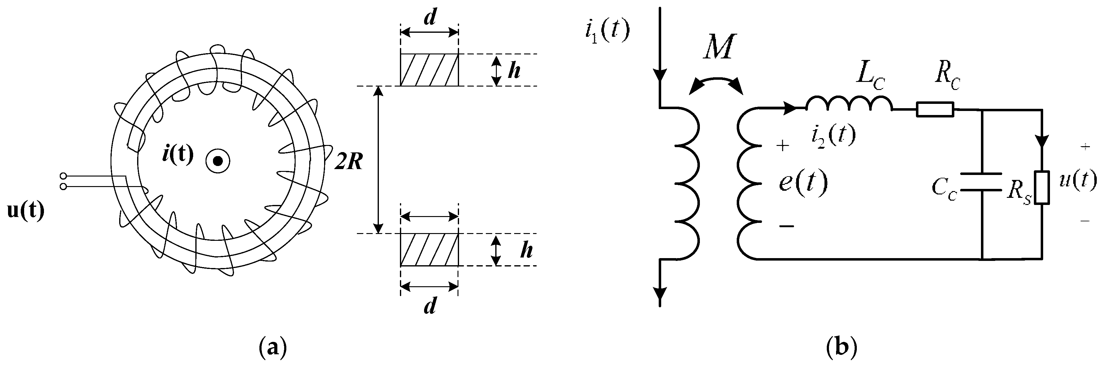
The Rogowski coil consists of two parts (
Figure 1a). One is the bobbin made of non-permeability magnetic materials (the material permeability can be viewed approximately equal to the permeability of vacuum μ
0). The bobbin has a uniform texture, and its cross section is generally rectangular or round. The other part is wound up on the frame tightly and evenly. The Rogowski coil induces a voltage signal that represents the testing current when flux changes.
If the terminal resistance is
Rs, the equivalent circuit of a Rogowski coil can be shown as
Figure 1b, and the output of Rogowski coil can be [
15,
16]:
Combining Equations (1) and (2) yields:
where
Cc is the distributed capacitance,
Rc is the resistance inside the coil,
Lc is the self-inductance of coil, and
M is the mutual inductance of coil. In most cases,
Cc is very little and can be omitted, so the output of Rogowski coil can be:
So when
, which means
, Equation (1) will be:
As the result the relationship between output voltage and input current is:
Output is proportional to the input, and the Rogowski coil is operating in self-integration model, and when
, Equation (1) will be:
At this time, the input current is equal to the integration of the output voltage, and the Rogowski coil is operating on an external-integration model.
3. Analysis on the Interference Sources Surrounding Overhead Transmission Lines
The electromagnetic environment surrounding the overhead transmission line is complicated. Thunder, lightning, discharges, and fault transit currents, except for the power frequency magnetic fields (PFMFs) around overhead transmission lines, will all generate electromagnetic interferences which can influence the measurement of a PCB Rogowski coil.
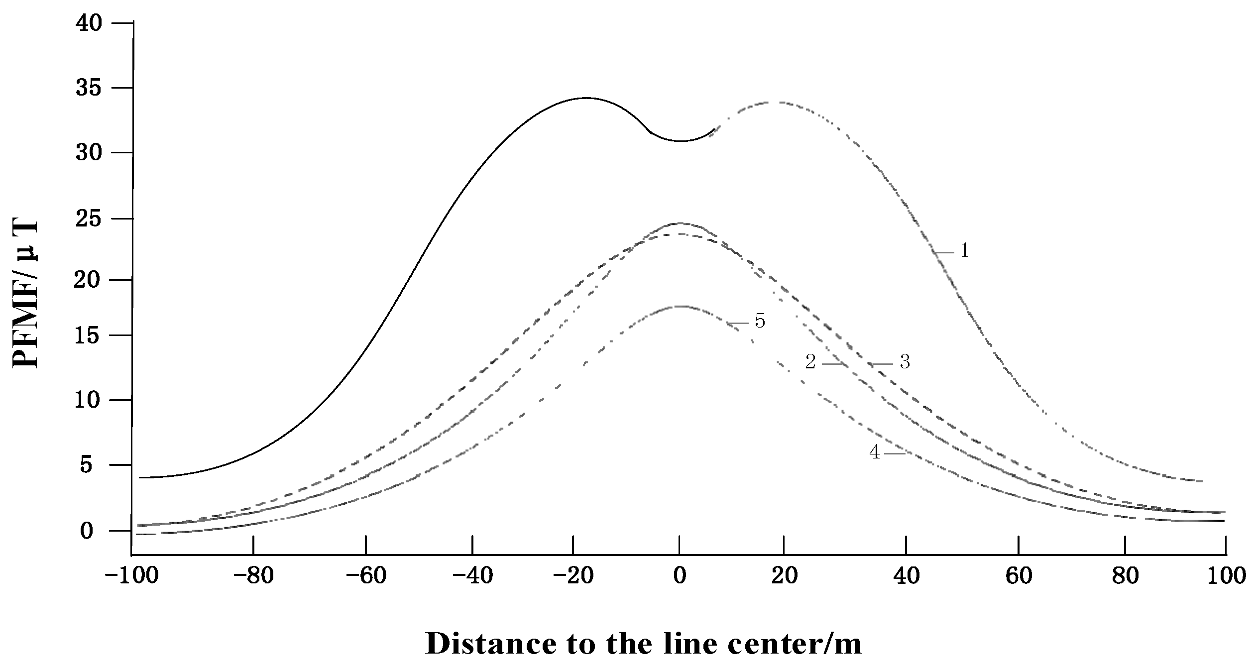
In order to estimate the magnetic field around the overhead transmission lines, [
17] calculated the magnetic field with five different conductor configurations. Assuming all the overhead transmission lines were 22 m from the ground, the selected point was 1 m above the ground. The calculated magnetic field distribution when the selected point from the overhead transmission lines is moved to a farther point is shown in
Figure 2, which shows that the PFMFs grow large when close to the overhead transmission lines. For the transient fault current sensors installed on overhead transmission lines, the monitoring object is the fault current which is several times larger than the nominal current and will cause much more interference to the transient fault current sensor, hence, the interference from an adjacent conductor is the main interference source for the transient fault current sensor, meanwhile, the interference caused by discharge will affect the sensor at all directions.
3.1. Analysis on the Interference of Adjacent Wire
When the Rogowski coil is installed on the overhead transmission line (Phase A), the magnetic fields generated by the adjacent line (Phases B and C) will also couple in the coil and produce an induced electromotive force as shown in
Figure 3a. The output of the sensor is the sum of all the induced voltages produced by the corresponding conductors. In order to estimate the interference from the adjacent line, phase B is taken as an example to analyze in
Figure 3b.
The distance between Phase-A and Phase-B conductors is
dAB as shown in
Figure 3b. If one point Q exists on the
ith turn of Rogowski coil, which is
r away from the circle center, and the distance between Phase-B conductor and point Q is
dAB, the angle θ
i is the included angle between
r and
dAB.
According to Ampere’s circuit law, the magnetic induction intensity generated by the Phase-B conductor on point Q is on the vertical line to line B
Q, and only the magnetic induction intensity perpendicular to the coil cross section,
i.e., the tangential direction of point Q, has a contribution to the induced electromotive force. The magnetic induction intensity component in the tangential direction of point Q is expressed as follows:
The total turns of a Rogowski coil is
N. If a Rogowski coil is wound evenly and tightly, the induced electromotive force can be expressed as the following continuous integral form:
On the basis of numerical calculations with MATLAB, when dAB > (R+d), e(t)=0. This result shows that as long as the adjacent conductor is beyond the PCB Rogowski coil and the winding of the PCB Rogowski coil is uniform, the interference from adjacent conductors can be omitted.
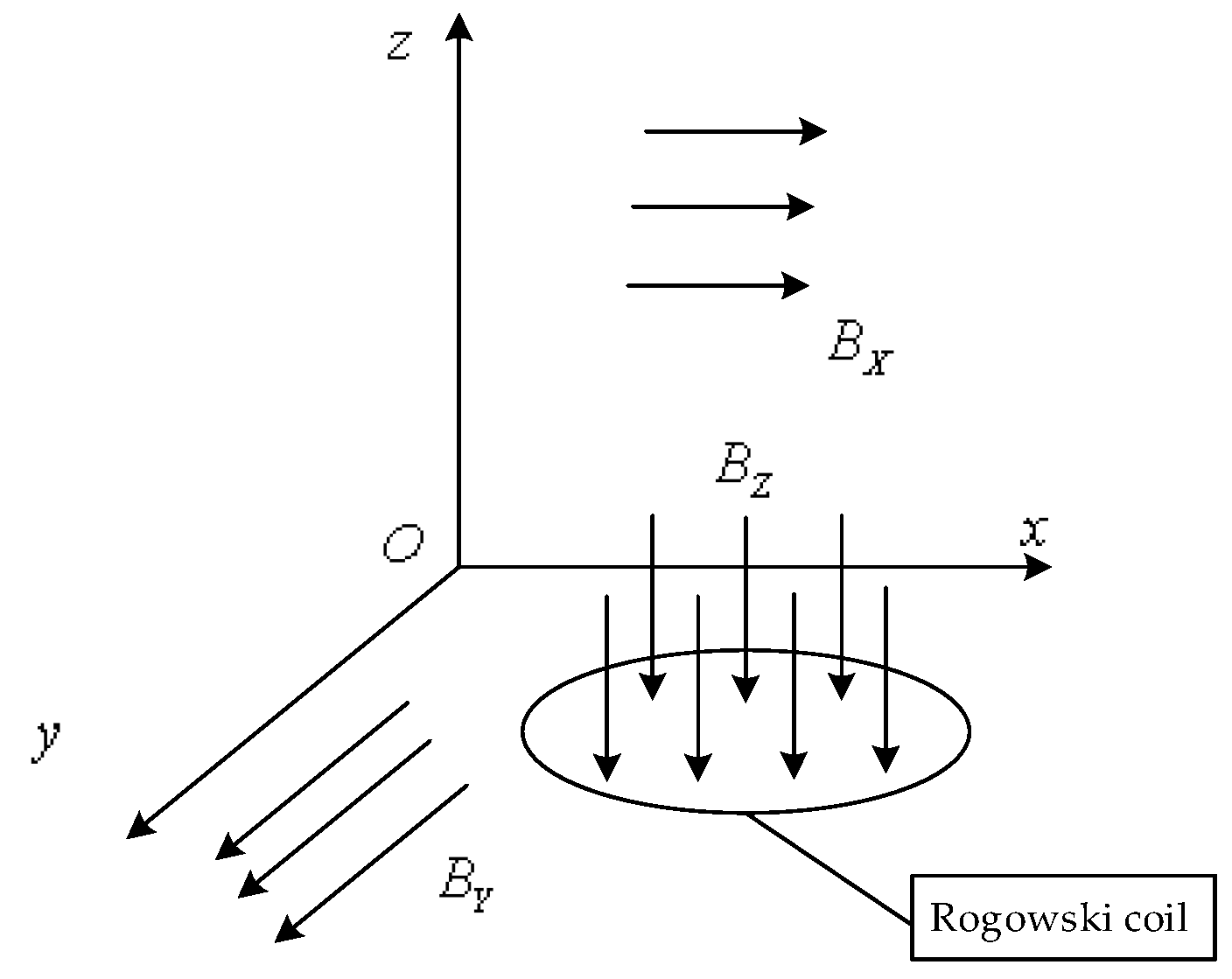
3.2. Analysis of Vertical External Magnetic Field Interference
There are various interfering magnetic fields around the sensor, which can be decomposed into
BX,
BY parallel to the plane
xOy where the bobbin is located, and
BZ perpendicular to the plane
xOy, as shown in
Figure 4 The impact of
BX and
BY on the Rogowski coil is same as that of an adjacent conductor, so only the impact of
BZ needs to be considered.
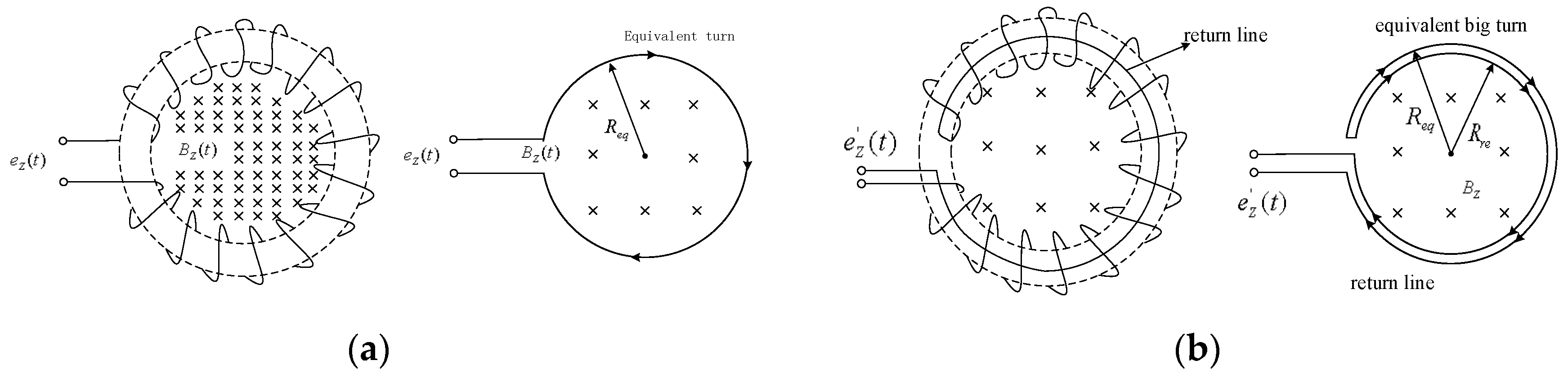
Bz is parallel to the cross-section where the Rogowski coil was located, thus, no induced electromotive force will be generated in the winding. However, the winding attaches on the coil bobbin spirally, thereby forming a structure similar to an annular solenoid. After the coil winds around the bobbin for one circle, an equivalent large turn is formed as shown in
Figure 5a.
Bz is perpendicular to the plane where large turns are located. When
Bz changes with time, the magnetic flux (Ψ
Z) will produce an induced electromotive force (
ez) in the Rogowski coil. Although the large turn has only one turn, its area is often significantly larger than the sectional area of windings. As a result, it will cause a significant error in the measured result. In practice, a return line [
18] shall be considered in a practical Rogowski coil to avoid the interference from
Bz as shown in
Figure 5b. The plane where the return line was located was parallel to plane
xOy. If the radius of the circle formed by the return line is
Rre and the induced electromotive force generated by
Bz on the return line is
ere, the final output induced electromotive force
e’z is equal to the sum of
ere and
ez. If
Rre is determined equal to the equivalent radius of the large turn (
Req),
ere is equal to
ez in numerical value but has an opposite direction. This opposite direction can be attributed to the opposite current in the return line to that of the equivalent large turn. Therefore, the effect of the vertical magnetic field on Rogowski coil performance can be effectively eliminated by adding return lines.
4. Design of Differential Winding PCB Rogowski Coil
For the fault current sensors installed on the overhead transmission line, the work temperature ranges from −40 °C to 85 °C, so the shape of the bobbin could change with the temperature and cause measurement errors. Meanwhile, the overhead transmission line requires the sensor to be installed without power interruption, so an open sensor structure is indispensable, so the main task to develop a transient fault current sensor based on the PCB Rogowski coil is how to eliminate the errors caused by temperature and interference.
4.1. Material Selection for the Rogowski Coil Bobbin
The coefficient of thermal expansion was considered when selecting the materials for the Rogowski coil bobbin. The coefficients of thermal expansion of some common materials are listed in
Table 1 [
19].
Rubber and polyethylene have significantly high thermal expansion coefficients, which will cause large temperature errors in environments where the working temperature changes greatly. Although ceramics have a significantly low coefficient of thermal expansion, they break easily and have a low rate of finished products. Long-term vibrations on overhead transmission lines and sudden electrodynamic forces on short circuits also occur; these phenomena can destroy the ceramic bobbins easily. As a result, epoxy resin was selected as the base material of our PCB.
4.2. Differential Winding of the Rogowski Coil
As stated before, if the Rogowski coil only has a signal line, the equivalent large turn is vulnerable to vertical magnetic field interference. A return line is indispensable to eliminate this interference. However, the sensor should be an open structure, so how to design the return line on an open structure sensor is a significant problem for fault current detection. Differential winding, which can achieve the same effect as return lines (
Figure 6 and
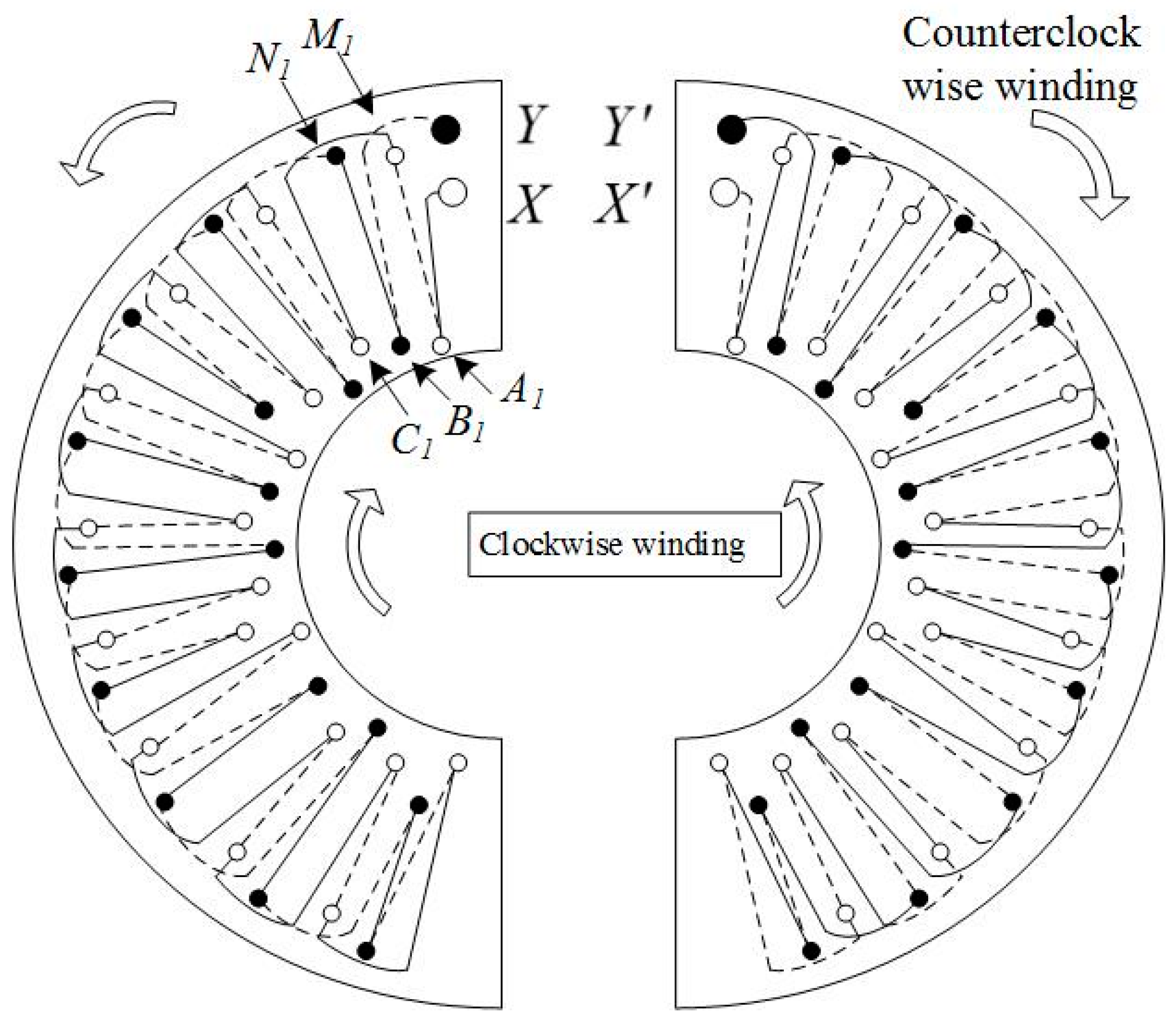
Figure 7) is chosen to eliminate this interference. Rows of vias were employed in each semi-ring. The same conductor was folded into two coils that twined on the bobbin towards the same direction in each semi-ring; this process is known as collinear twisted pair differential winding. One coil was defined as clockwise winding, and the other was counterclockwise winding. Given that the currents in these two coils flow in the opposite direction, a 180° difference exists in their phase position. Two coils were wound tightly in a twisted pair to ensure that the branch and return line were strictly symmetric. The generated coupling magnetic fluxes had the same absolute value but opposite directions. They offset each other, thus neutralizing the common-mode signal and eliminating vertical magnetic field interference.
Two rows of vias were set on one side of the external ring of the semicircular printed board, and three rows of vias were set on one side of the internal ring. They were marked from external to internal as Rows N, M, C, B and A. The distances between these rows of vias and the circle center were recorded as
RN,
RM,
RC,
RB and
RA. One end of the semi-ring comprised the starting via X and end via Y of the turn. External Rows N and M had 58 vias, which were uniformly distributed at an equivalent radian interval of π/58. Internal Rows C, B, and A had 39 vias, which were uniformly distributed at an equivalent radian interval of π/39. The copper foil connections of turns in this design are shown in
Figure 7.
In
Figure 7, the full lines are front connections and the dotted lines are back connections. The hollow dots are the vias on the clockwise winding, and the solid dots are the vias on the counterclockwise winding. The clockwise winding and counterclockwise winding form one differential line pair. The current in the counterclockwise winding was the complementary signal on the clockwise winding. The left semi-ring was taken as an example. The vias from top to bottom were marked as Np, Mp, Cq, Bq, and Aq, where p ranged from 1 to 58 and q ranged from 1 to 39. In this way, the clockwise winding can be expressed as X-A1-M1-C1-M2-B2-M3-A3-M4-C3, …, and the vias of Row M were connected with Rows A, B, and C successively until M58 was connected with C39. On the backboard, C30 was connected with N58 and counterclockwise winding began at N58. The counterclockwise winding was from bottom to top, but the turns remained in the same direction as the clockwise winding. The counterclockwise winding was N58-B39-N57-C39-N56-A38, …, and the vias of Row N were connected with those of Rows A, B, and C successively until B1 was connected with Y. When the front Row N was connected with Rows A, B, and C, it reached across the external side of Row M along a part of small arc. When Back Row M was connected with Rows A, B, and C, it also reached across the external side of Row N along a part of a small arc. The front and back arcs had an equal radius, and the total span was equal. The entire coil was composed of two completely identical semi-rings rather than two mirrored semi-rings. The left semi-ring can be the right one after flipping horizontally. The front wiring of the left semi-ring was the same as the back wiring of the right semi-ring. As a result, two pieces of signal lines are twisted back and forth, thus making
Rre and
R strictly equal. However, the signal phase were completely opposite. The induced electromotive forces produced by the vertical disturbing magnetic field in the equivalent large turn of clockwise winding and the equivalent large turn of counterclockwise winding had the same absolute value but opposite direction. They offset each other, thus, the disturbance of the vertical disturbing magnetic field was eliminated.
4.3. Parameters of the Rogowski Coil
Figure 8 illustrates a physical Rogowski coil composed of two semi-rings. The geometric parameters are presented in
Table 2.
Three rows of internal vias of the PCB coil were successively connected to two rows of external vias to form six specifications of small turns (
Table 3).
The connection between Y and Y′ was identified as turn type 5,
i.e., the turn formed by NB. The total mutual inductance [
20] of the coil was the sum of the mutual inductance of different types of turns:
where
Mi is the mutual inductance of the
ith type of small turn;
Ni is the number of turns of the
ith type of small turn;
ROi and
RIi are the outer radius and inner radius of the
ith type of small turn, respectively. The structure of multiple rows of vias realized counterclockwise winding of coil and made effective use of the space on the PCB. The self-inductance can be expressed as follows:
The main frequency component of the fault current ranges from 50 Hz to several hundred kHz, so the work frequency band of the sensor should cover most of the frequency band. A T-integrating circuit was designed for the PCB Rogowski coil as shown in
Figure 9.
The transfer function of Rogowski coil can be obtained from
Figure 1b, so the total transfer function of the sensor was [
21,
22]:
If the appropriate parameters of
Rf,
Rs,
R,
C and
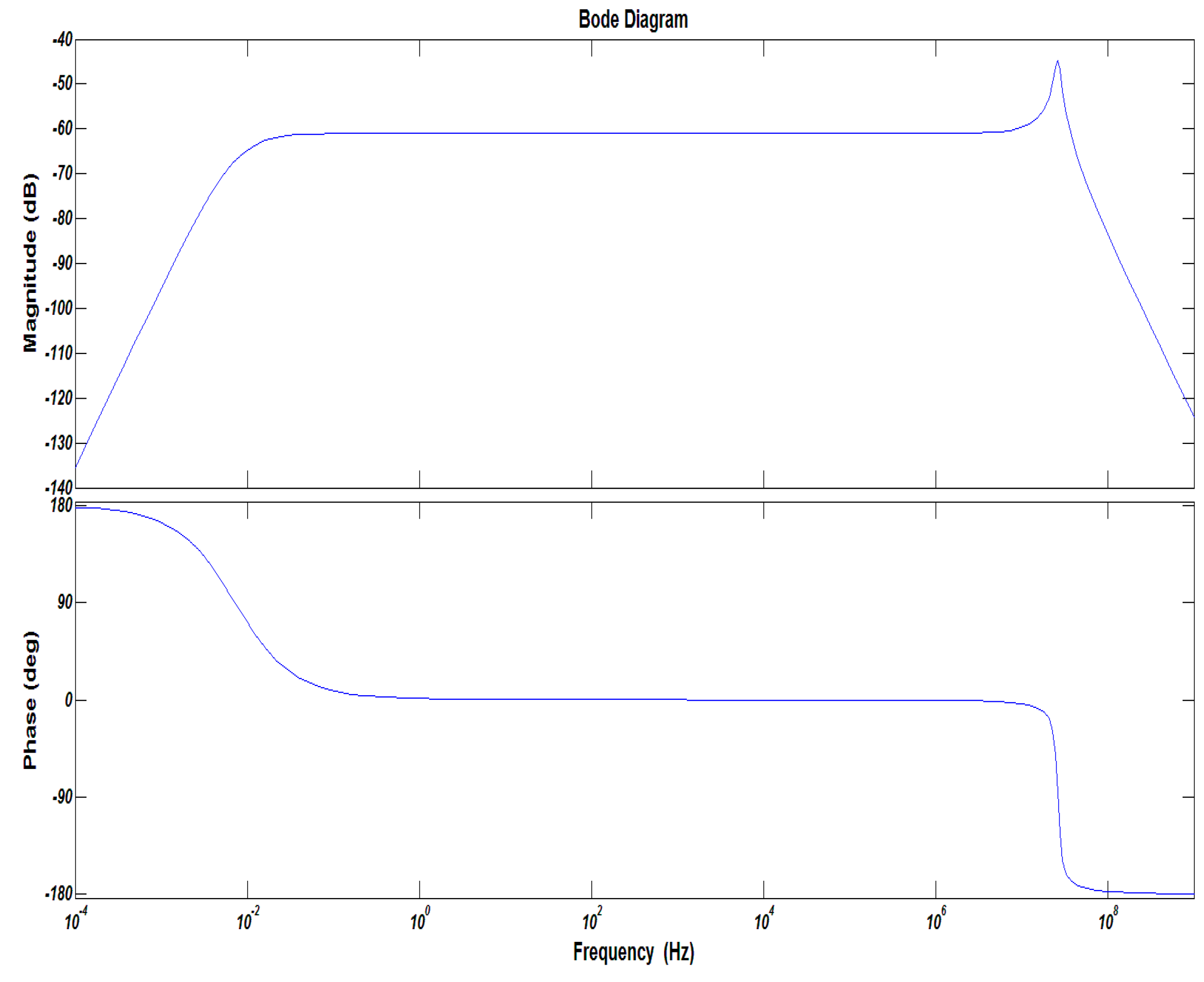
C0 are selected, the corresponding performance can be obtained. If the work frequency bandwidth of the sensor was 30 Hz to 1 MHz, the parameters of the integrator are listed in
Table 4, and the corresponding frequency response is shown in
Figure 10.
5. Performance Test the PCB Rogowski Coil
In order to verify the performance of the proposed sensor, a serial test, including the frequency response, linearity, anti-interference performance as well as a comparison with commercial sensors were conducted.
5.1. Linearity Test
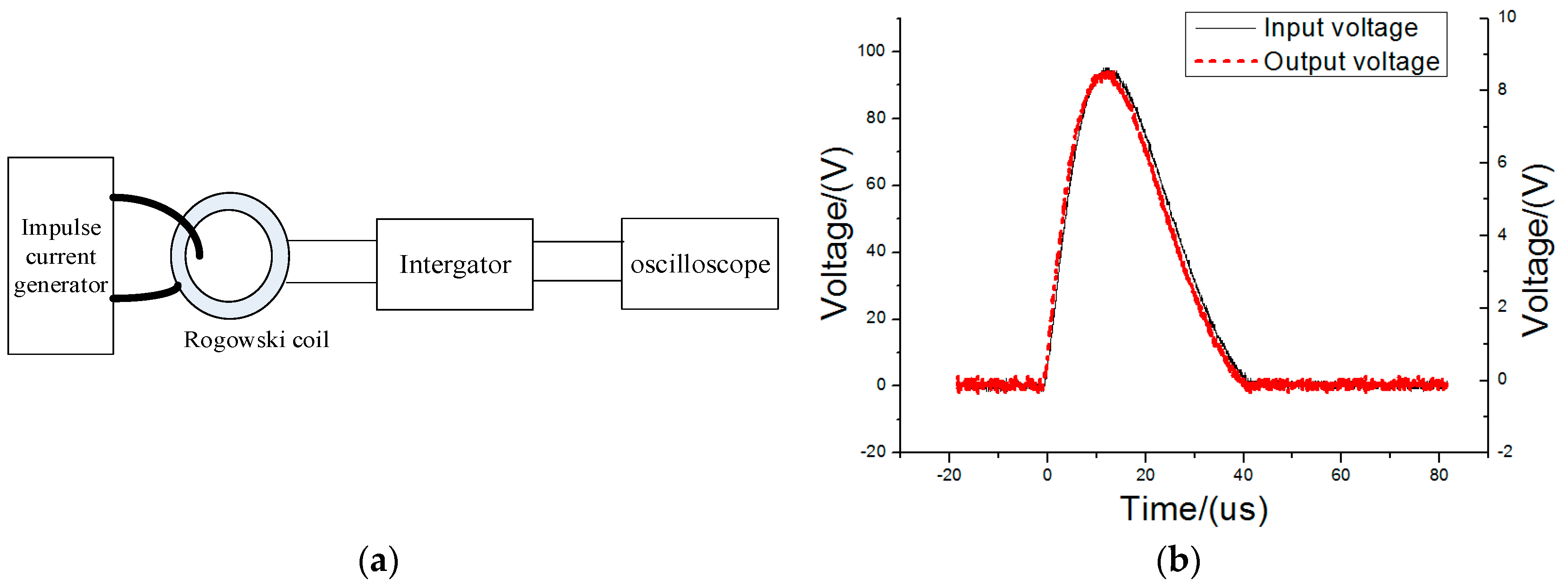
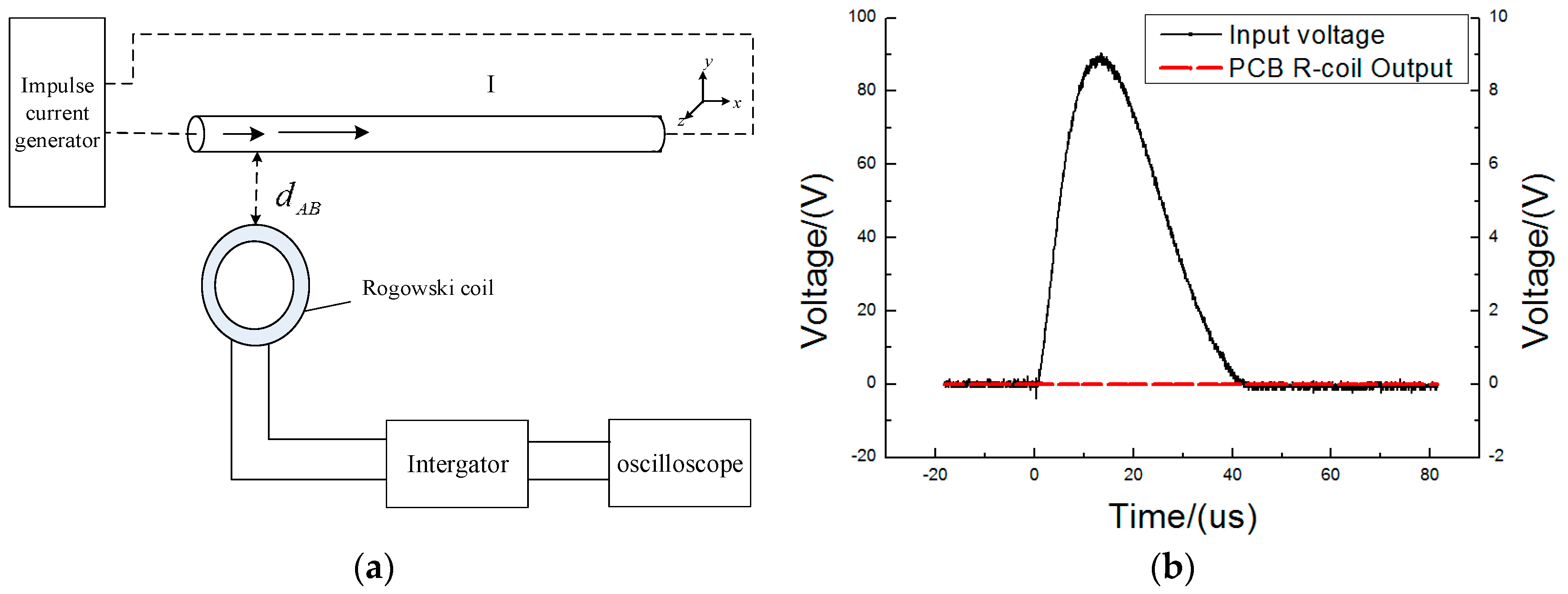
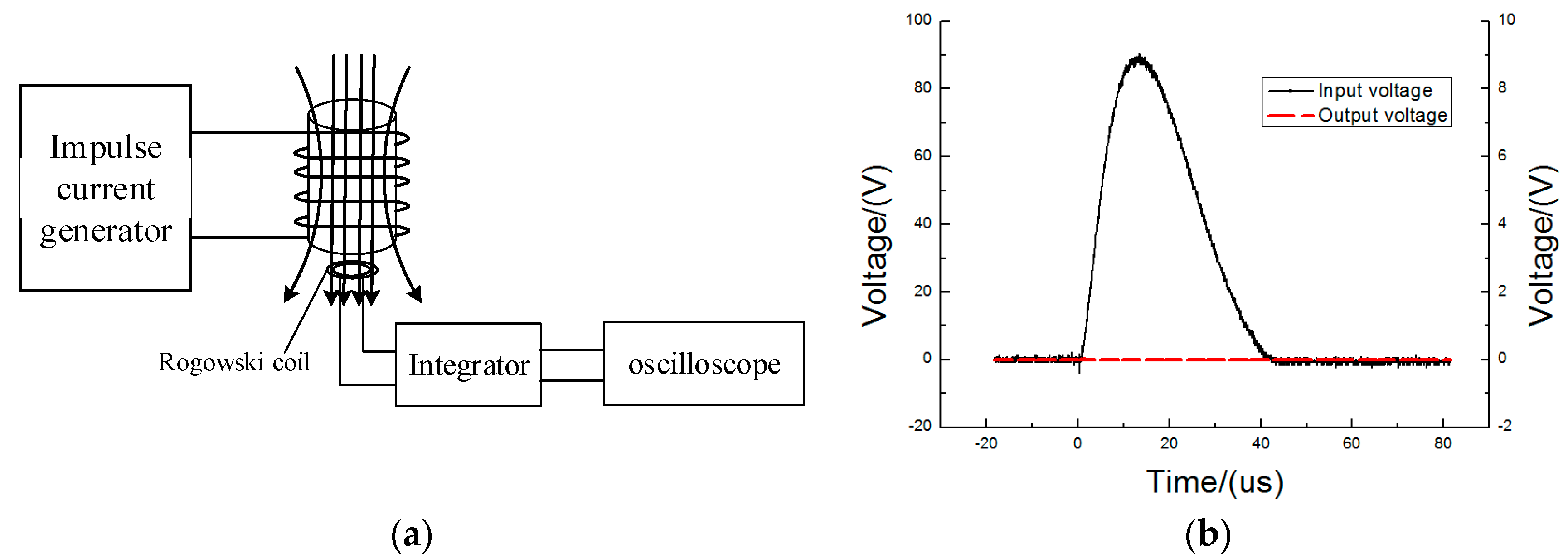
An experimental platform was established to test the high-frequency transient current measurement accuracy of the proposed PCB Rogowski coil (
Figure 11a). The impulse current generator can produce 8–20 µs impulse currents to a peak value 50 kA. The output of the impulse current generator and the output of the PCB Rogowski coil were connected onto Channels 1 and 2 of a DPO 5204 digital oscilloscope, respectively. When the impulse current is 10,160 A, the output of the PCB coil is presented in
Figure 11b.
Figure 11b shows that the output of the PCB coil is almost the same as the input waveform, so the PCB coil has a sufficient bandwidth to detect the fault current.
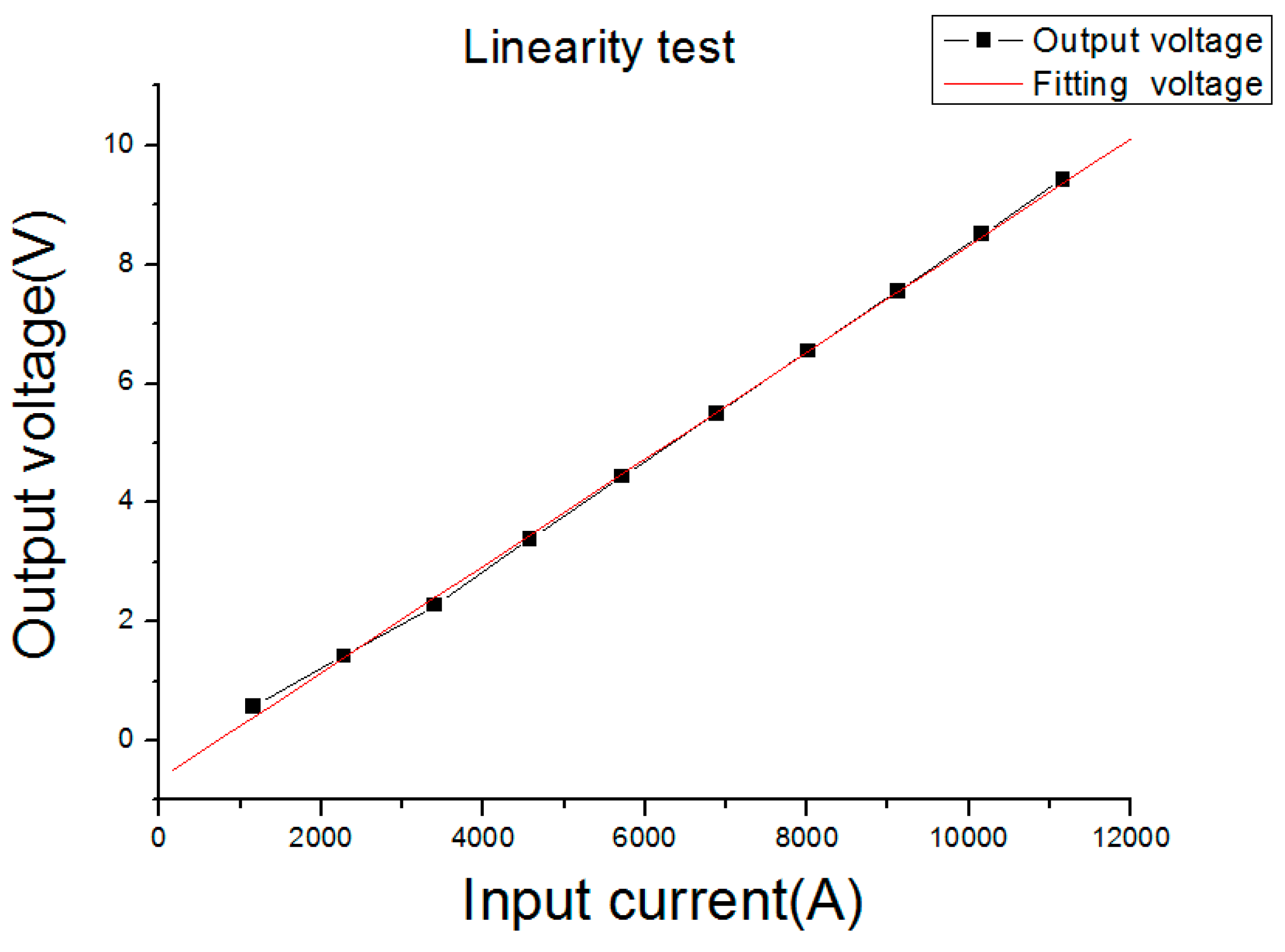
Figure 12 shows the output voltage of the PCB Rogowski coil under different input currents. From
Figure 12, the linearity of the PCB Rogowski coil was no more than 2% under a 8–20 µs lightning impulse wave in a 12,000 A range.
5.2. Test of Adjacent Wire Interference
The output line of the impulse current generator was extended to simulate the effect of adjacent wires on the PCB Rogowski coil. The plane where the PCB Rogowski coil was located was perpendicular to the wire (
Figure 13a). The amplitude of the impulse current generator was set at 2310 A, and the distance between the wire and coil was controlled at 3 and 6 cm. The inputs and outputs of the PCB Rogowski coil were recorded (
Figure 13b). The different directions of coil and wire were further changed to test the outputs under different conditions (
Table 5).
In
Figure 13b, the PCB coil was 3 cm away from the wire, and the coil plane was perpendicular to the wire. When a 2002 A impulse current was set in the adjacent wire, a 96.0 V impulse voltage was generated in Channel 1, while the Rogowski coil output was only 120 mV. Hence, the Rogowski coil with two semi-rings could resist the interference of adjacent wires well.
5.3. Test of Vertical Magnetic Field Interference
The impulse current generator was used to produce an 8/20 interference current waveform and to test the effect of vertical wire on the PCB Rogowski coil. A wire that transmitted the interference current was wound on a cylinder to form a solenoid. This solenoid would generate a uniform magnetic field perpendicular to the horizontal plane, as shown in
Figure 14a. The impulse current was set to 1030, 1565 and 2020 A. The vertical disturbing magnetic field was put perpendicular to the PCB Rogowski coil (
Figure 14a). The outputs of a conditioning circuit were measured (
Table 6).
According to
Table 6 and
Figure 14b, when the interference current increased from 1030 A to 2000 A, the output of the Rogowski coil was about 450 mV. Thus, the designed PCB Rogowski coil had good resistance to the vertical magnetic field interference.
5.4. Test of Frequency Response
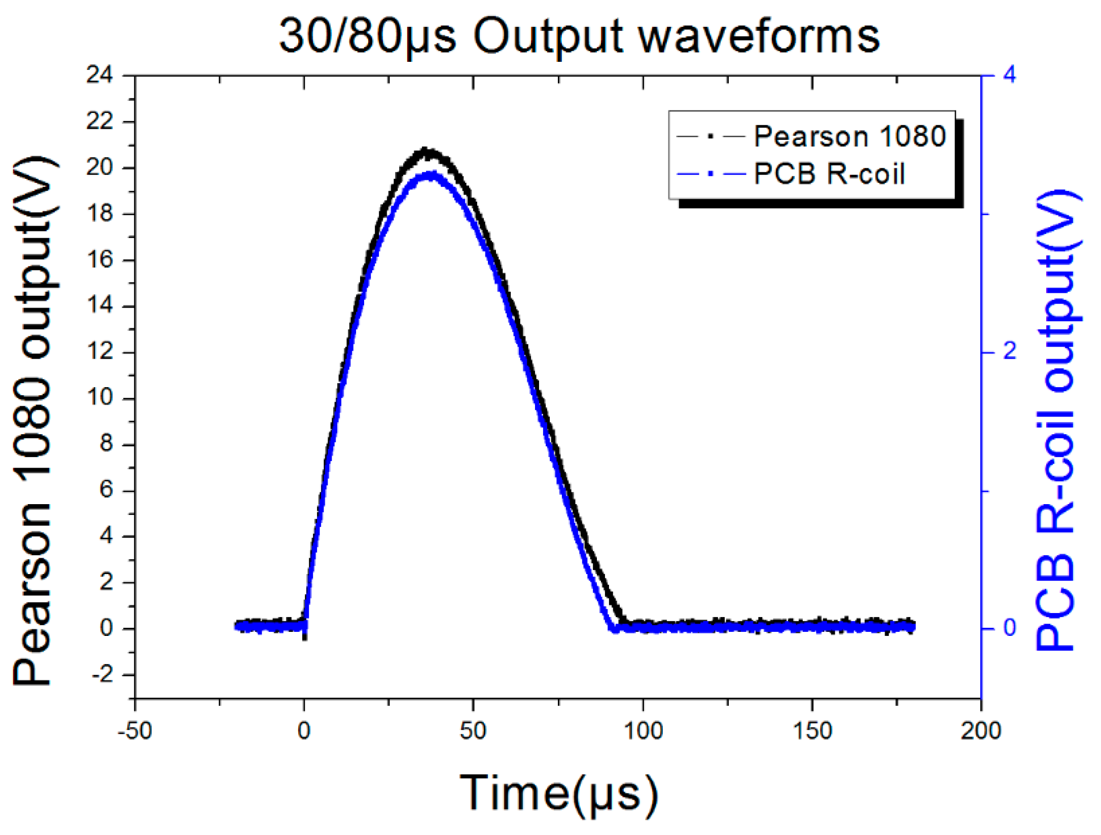
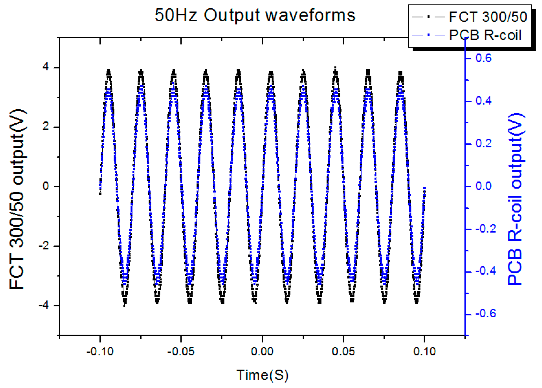
In order to test the frequency response of the proposed sensor, 50 Hz, 8/20 μs and 30/80 μs currents were selected as the current source, so the frequency could cover 50 Hz to 43.75 kHz. The parameters of the current source were listed in
Table 7 and the test results were listed in
Table 8, while the output waveforms of the PCB Rogowski coil with different source were listed in
Figure 15,
Figure 16 and
Figure 17. The output waveforms are almost the same with the standard current source, meanwhile, the input, the output ratio is 1185:1, 1197:1 and 1208:1, corresponding to the 50 Hz, 8/20 μs and 30/80 μs, respectively, so the work frequency bandwidth covers the bandwidth of the three sources.
5.5. Performance Comparation Between the Commecial Sensors
In order to compare the performance among the newly designed sensor and commercial ones, two commercial sensors, a Pearson 4997 and a FCT 200 were selected. Their main specifications are shown in
Table 9.
After setting the input current range from 1000 A to 5000 A, and recording the output of different sensors,
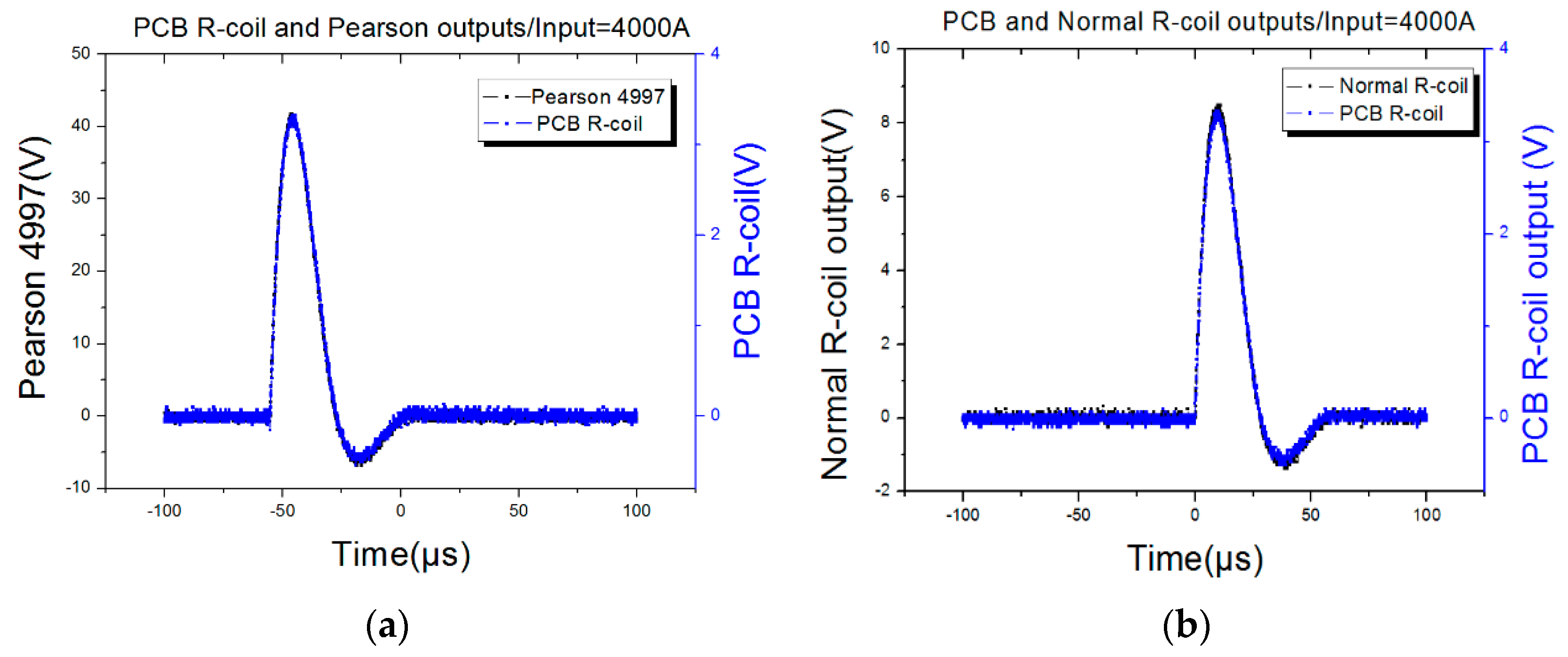
Figure 18 shows that when the input current was 4000 A, the output waveform of the proposed sensor was almost the same as the output of the Pearson 4997 and FCT 200 but for the output ratio. If the Pearson 4997 is considered as the standard, the outputs among the three sensors are listed in
Table 10. From
Table 10, the linear correlation coefficient of the PCB Rogowski coil is 0.99959, and that of the FCT 200 is 0.99969, so there is nearly no difference between the proposed sensor and commercial ones.
6. Field Application
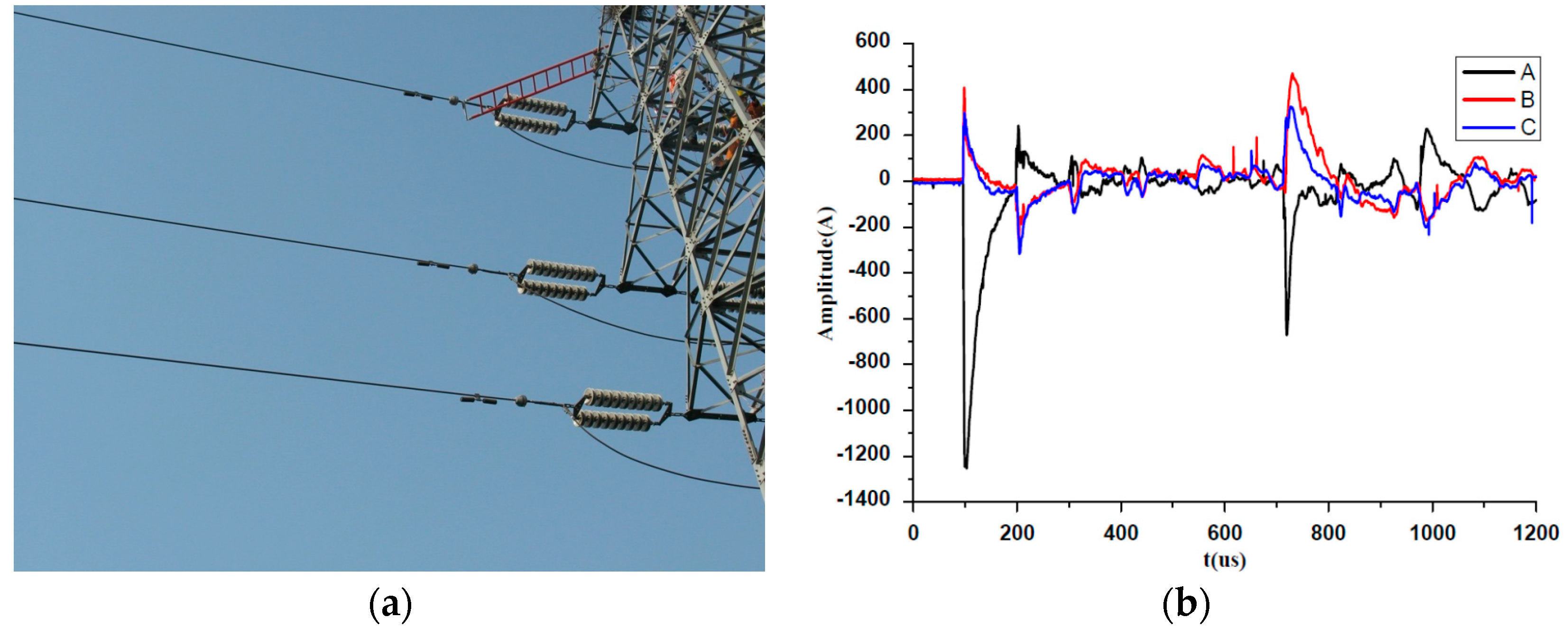
The newly designed sensor has been implemented in an overhead transmission line online monitoring device named distribution fault locator as shown in
Figure 19. The low frequency components under 1 kHz were eliminated by a high pass filter because only the high frequency was of concern in the application.
Figure 19 shows the amplitude of the captured fault travelling wave current was 1254 A, the half wavelength was about 26 μs, while the rise time was about 5 μs, which was fully adequate for transient fault current detection, so the designed PCB sensor has excellent performance, as good as that of the commercial ones.
7. Conclusions
An open structure PCB Rogowski coil has been presented. The mechanism of interference around the overhead transmission line and the guidelines of anti-interference were established. The proposed PCB Rogowski coil according to the guidelines was designed and tested. For transient fault current detection, the proposed PCB Rogowski coil has almost the same excellent performance in work frequency bandwidth and linearity as commercial ones. Furthermore, the strictly symmetrical structure of the PCB Rogowski coil could eliminate almost all the magnetic field interference from the radial direction, so it is immune from the interference of adjacent conductors, while, the differential winding of the PCB Rogowski coil could offset the axial magnetic field interference, and as a result, the proposed sensor has perfect anti-interference performance, which was the key to measuring transient fault currents. Through the tests, the proposed PCB Rogowski coil was proved to be more machinable, repeatable, and of commercial value.
Acknowledgments
This research was funded by a grant (No. 51307109) from the National Natural Science Foundation of China and a grant (No. 2013DFG71630) from the International S & T Cooperation Projects of China and the State Grid Corporation of China.
Author Contributions
The idea of this work was proposed by Yadong Liu, Qian Yong, Gehao Sheng and Xiuchen Jiang. Xiaolei Xie and Yue Hu performed the experiments and analyzed the results. Yadong Liu and Xiaolei Xie wrote the paper.
Conflicts of Interest
The authors declare no conflict of interest.
References
- Le Blond, S.T.; Deng, Q.; Burgin, M. High frequency protection scheme for multi-terminal HVDC overhead lines. In Proceedings of the 12th IET International Conference on Developments in Power System Protection (DPSP), Copenhagen, Denmark, 31 March–3 April 2014; pp. 1–5.
- Lei, A.Y.; Dong, X.Z.; Shi, S.X.; Wang, B. A novel current travelling wave based single-ended fault location method for locating single-phase-to-ground fault of transmission line. In Proceedings of the 2015 50th International Universities on Power Engineering Conference (UPEC), Shropshire(Shrewsbury), UK, 1–4 September 2015; pp. 1–6.
- Ouyang, Y.; He, J.; Hu, J.; Wang, S.X. A current sensor based on the giant magnetoresistance effect: Design and potential smart grid applications. Sensors 2012, 12, 15520–15541. [Google Scholar] [CrossRef] [PubMed]
- Varskyi, H.; Tankevych, S.; Hrechko, V. Design features of electromagnetic transducer as a part of electronic current transformer. In Proceedings of the 2014 IEEE International Conference on Intelligent Energy and Power Systems (IEPS), Kyiv, Ukraine, 2–6 June 2014; pp. 60–62.
- Sun, C.; Wen, Y.; Li, P.; Ye, W.; Yang, J.; Qiu, J.; Wen, J. Self-contained wireless Hall current sensor applied for two-wire zip-cords. IEEE Trans. Magn. 2016, 99, 1–127. [Google Scholar] [CrossRef]
- Karasawa, D.; Sonehara, M.; Kitazawa, S.; Sato, T. Development of optical probe current sensor with Kerr effect for power electronics. In Proceedings of the IEEE Sensors 2014, Valencia, Spain, 2–5 November 2014; pp. 1928–1931.
- Zhang, G.; Liu, Y.; Xie, S. Positional error analysis of PCB Rogowski coil for high accuracy current measurement. Adv. Mech. Eng. 2013, 5, 375301. [Google Scholar] [CrossRef]
- Di, Z.G.; Jia, C.R.; Zhang, J.X. PCB Rogowski coil for electronic current transducer. Sens. Transducers 2014, 171, 206–213. [Google Scholar]
- Han, R.Y.; Wu, J.W.; Ding, W.D.; Jing, Y.; Zhou, H.B.; Liu, Q.J.; Qiu, A.C. Hybrid PCB Rogowski coil for measurement of nanosecond-risetime pulsed current. IEEE Trans. Plasma Sci. 2015, 43, 3555–3561. [Google Scholar] [CrossRef]
- Fritz, J.N.; Neeb, C.; de Doncker, R.W. A PCB Integrated Differential Rogowski Coil for Non-Intrusive Current Measurement Featuring High Bandwidth and dv/dt Immunity. Available online: https://eldorado.tu-dortmund.de/handle/2003/33955 (accessed on 16 May 2016).
- Ghanbari, T.; Farjah, A. Application of Rogowski search coil for stator fault diagnosis in electrical machines. IEEE Sens. J. 2014, 14, 311–312. [Google Scholar] [CrossRef]
- Ardila-Rey, J.A.; Albarracín, R.; Álvarez, F.; Barrueto, A. A validation of the spectral power clustering technique (SPCT) by using a Rogowski coil in partial discharge measurements. Sensors 2015, 15, 25898–25918. [Google Scholar] [CrossRef] [PubMed]
- Chen, Q.; Li, H.B.; Huang, B.X.; Dou, Q.Q. Rogowski sensor for plasma current measurement in J-TEXT. IEEE Sens. J. 2009, 9, 293–296. [Google Scholar]
- Sheng, Z.Z.; Han, B.; Qing, M.A. The analysis of the factors affecting the performance of Clamp Rogowski coil. In Proceedings of the 2014 International Conference on Power System Technology (POWERCON), Chengdu, China, 20–22 October 2014; pp. 1446–1450.
- Metwally, I.A. Design of different self-integrating and differentiating Rogowski coils for measuring large-magnitude fast impulse currents. IEEE Trans. Instrum. Meas. 2013, 62, 2303–2313. [Google Scholar] [CrossRef]
- Ahmed, A.; Coulbeck, L.; Castellazzi, A.; Johnson, C.M. Design and test of a PCB Rogowski coil for very high dI/dt detection. In Proceedings of the 2012 15th Conference on International Power Electronics and Motion Control (EPE/PEMC), Novi Sad, Serbia, 4–6 September 2012.
- Shao, F.Y. Phase conductor configuration and power frequency electromagnetic environment of UHV transmission lines In China. Power Syst. Technol. 2005, 08, 1–7. [Google Scholar]
- Tao, T.; Zhao, Z.; Ma, W.; Pan, Q.; Hu, A. Design of PCB Rogowski coil and analysis of anti-interference property. IEEE Trans. Electromagn. Compat. 2016, 58, 344–355. [Google Scholar] [CrossRef]
- Gong, Y.Z. Study on Current Sensor Based on PCB Rogowski Coil; Jiangsu University: Zhenjiang, China, 2009. [Google Scholar]
- Ferkovic, L.; Ilic, D.; Lenicek, I. Influence of axial inclination of the primary conductor on mutual inductance of a precise Rogowski coil. IEEE Trans. Instrum. Meas. 2015, 64, 3045–3054. [Google Scholar] [CrossRef]
- Farjah, E.; Givi, H.; Ghanbari, T. Application of an efficient Rogowski coil sensor for switch fault diagnosis and capacitor ESR monitoring in non-isolated single switch DC-DC converters. IEEE Trans. Power Electron. 2016. [Google Scholar] [CrossRef]
- Heng, S.K.; Han, Y.C.; Zhang, J.S.; Wei, H.R.; Zheng, X.L.; Wang, C.L.; Zhu, W. Design of PCB Rogowski coil current transformer for fault indicators in distribution networks. Water Resour. Power 2015, 33, 186–189. [Google Scholar]
Figure 1.
Principle of a Rogowski Coil. (a) Structure Diagram of a Rogowski coil; (b) Equivalent circuit of a Rogowski coil.
Figure 1.
Principle of a Rogowski Coil. (a) Structure Diagram of a Rogowski coil; (b) Equivalent circuit of a Rogowski coil.
Figure 2.
Five PFMF distributions in the UHV overhead transmission line route at 1 m height from the ground. 1—Parallel arrangement of phase conductor; 2—Triangle arrangement of phase conductor; 3—Common-tower double-circuit overhead transmission line; 4—Compact type (10 splits); 5—Compact type (12 splits).
Figure 3.
Interference of adjacent conductors. (a) Interferences of adjacent phases; (b) Effect of the Phase-B magnetic field.
Figure 3.
Interference of adjacent conductors. (a) Interferences of adjacent phases; (b) Effect of the Phase-B magnetic field.
Figure 4.
The impact of orthogonal magnetic field.
Figure 4.
The impact of orthogonal magnetic field.
Figure 5.
The return line of Rogowski coil. (a) Equivalent large turn without return line; (b) Rogowski coil with the return line.
Figure 5.
The return line of Rogowski coil. (a) Equivalent large turn without return line; (b) Rogowski coil with the return line.
Figure 6.
Structure of rows of vias.
Figure 6.
Structure of rows of vias.
Figure 7.
Connections of turns.
Figure 7.
Connections of turns.
Figure 8.
Physical picture of the designed Rogowski coil.
Figure 8.
Physical picture of the designed Rogowski coil.
Figure 9.
The schematic diagram of integrator.
Figure 9.
The schematic diagram of integrator.
Figure 10.
The frequency response of the proposed sensor.
Figure 10.
The frequency response of the proposed sensor.
Figure 11.
The verification of the PCB Rogowski Coil. (a) Experimental linearity circuit; (b) Waveform comparison between the input and PCB coil output.
Figure 11.
The verification of the PCB Rogowski Coil. (a) Experimental linearity circuit; (b) Waveform comparison between the input and PCB coil output.
Figure 12.
Linearity test fitting curve.
Figure 12.
Linearity test fitting curve.
Figure 13.
The test of adjacent wire interference. (a) Testing diagram of adjacent wire interference; (b) The waveform comparison at 2002 A and 3 cm.
Figure 13.
The test of adjacent wire interference. (a) Testing diagram of adjacent wire interference; (b) The waveform comparison at 2002 A and 3 cm.
Figure 14.
The test of vertical magnetic field interference. (a) Testing diagram of vertical magnetic field interference; (b) The waveform comparison at vertical magnetic field interference.
Figure 14.
The test of vertical magnetic field interference. (a) Testing diagram of vertical magnetic field interference; (b) The waveform comparison at vertical magnetic field interference.
Figure 15.
50 Hz output waveforms.
Figure 15.
50 Hz output waveforms.
Figure 16.
8/20 impulse current output waveforms.
Figure 16.
8/20 impulse current output waveforms.
Figure 17.
30/80 impulse current output waveforms.
Figure 17.
30/80 impulse current output waveforms.
Figure 18.
Output waveforms of 8–20 µs impulse current. (a) PCB R-coil and Pearson output waveforms; (b) PCB and Normal R-coil output waveforms.
Figure 18.
Output waveforms of 8–20 µs impulse current. (a) PCB R-coil and Pearson output waveforms; (b) PCB and Normal R-coil output waveforms.
Figure 19.
The field application of the proposed sensor. (a) Locators installed in field; (b) The captured fault current waveforms.
Figure 19.
The field application of the proposed sensor. (a) Locators installed in field; (b) The captured fault current waveforms.
Table 1.
Coefficients of (linear) thermal expansion of common bobbin materials.
Table 1.
Coefficients of (linear) thermal expansion of common bobbin materials.
| Material | Rubber | Polyethylene | Epoxy Resin | Ceramic |
|---|
| Coefficient of expansion/(10−6/°C) | 200–300 | 126–160 | 60–80 | 1.0–7.7 |
Table 2.
Geometric parameters of the PCB Rogowski coil.
Table 2.
Geometric parameters of the PCB Rogowski coil.
| Inner Radius of the Bobbin | Outer Radius of the Bobbin | Thickness | RA | RB | RC | RM | RN |
|---|
| 24.0 mm | 39.0 mm | 3.0 mm | 25.5 mm | 26.5 mm | 27.5 mm | 36.5 mm | 38.0 mm |
Table 3.
Specifications of small turns.
Table 3.
Specifications of small turns.
| Turn Type | 1 | 2 | 3 | 4 | 5 | 6 |
|---|
| Outer Row | M | M | M | N | N | N |
| Outer Row | A | B | C | A | B | C |
| Turns | 38 | 38 | 40 | 38 | 38 | 40 |
| Inner radius (mm) | 25.5 | 26.5 | 27.5 | 25.5 | 26.5 | 27.5 |
| Outer radius (mm) | 36.5 | 36.5 | 36.5 | 38.0 | 38.0 | 38.0 |
Table 4.
Parameters of the PCB Rogowski Coil sensor.
Table 4.
Parameters of the PCB Rogowski Coil sensor.
| Parameters | Values | Parameters | Values | Parameters | Values |
|---|
| RC | 46.3 Ω | M | 47.346 nH | R0 | 2 MΩ |
| LC | 1.8283 µH | Rs | 20 MΩ | C0 | 22 µF |
| CC | 20.12 pF | Rf | 1 kΩ | C | 1 µF |
Table 5.
Interference test of adjacent wire.
Table 5.
Interference test of adjacent wire.
| Coil Flat Position | xz | xy | yz |
|---|
| dAB (cm) | 3 | 6 | 3 | 6 | 3 | 6 |
| Impulse current (A) | 1969 | 1969 | 1901 | 1901 | 2002 | 2002 |
| Peak value of channel 1 (V) | 94.4 | 94.4 | 91.2 | 91.2 | 96 | 96 |
| Peak value of channel 2 (mV) | 220 | 220 | 140 | 140 | 120 | 160 |
| Error% | 0.233 | 0.233 | 0.153 | 0.153 | 0.125 | 0.167 |
Table 6.
Test results of vertical magnetic field interference.
Table 6.
Test results of vertical magnetic field interference.
| Impulse current (A) | 1030 | 1565 | 2020 |
|---|
| Peak value of channel 1 (V) | 48 | 64 | 94 |
| Peak value of channel 2 (mV) | 420 | 450 | 480 |
| Error% | 0.875 | 0.7 | 0.51 |
Table 7.
Models and equipment parameters.
Table 7.
Models and equipment parameters.
| Parameters | Source 1 | Source 2 | Source 3 |
|---|
| Current parameters | 50 Hz | 8/20 (μs) | 30/80 (μs) |
| Source models | PY002 | KV2103-G-020 | MWG001 |
| Standard CT | FCT 300/50 150 A/V | Pearson 4997 100 A/V | Pearson 1080 200 A/V |
Table 8.
Results of the frequency experiments.
Table 8.
Results of the frequency experiments.
| Current Waveforms | 50 Hz | 8/20 (us) | 30/80 (us) |
|---|
| Standard CT outputs (V) | 2.77 | 41.42 | 20.78 |
| Input current (A) | 415 | 4142 | 4156 |
| PCB R-coil outputs (V) | 0.35 | 3.46 | 3.44 |
| PCB R-coil ratio | 1185:1 | 1197:1 | 1208:1 |
Table 9.
The main specifications of two commercial sensors.
Table 9.
The main specifications of two commercial sensors.
| Sensor | Pearson Model 4997 | Normal Rogowski Coil FCT 200 |
|---|
| I/O ratio | 100 A/1V | 500 A/1V |
| Bandwidth (−3 dB) | 0.5 Hz–15 MHz | 1 Hz–1 MHz |
| Accuracy | 1% | 1% |
Table 10.
Outputs of different sensors.
Table 10.
Outputs of different sensors.
| No. | Setting Input Current (A) | Pearson 4997 Output (V) | PCB R-Coil Output (V) | FCT 200 Output (V) |
|---|
| 1 | 1000 | 12.0 | 1.00 | 2.54 |
| 2 | 2000 | 23.3 | 1.98 | 4.62 |
| 3 | 3000 | 31.9 | 2.66 | 6.52 |
| 4 | 4000 | 41.8 | 3.46 | 8.49 |
| 5 | 5000 | 51.7 | 4.38 | 10.41 |
© 2016 by the authors; licensee MDPI, Basel, Switzerland. This article is an open access article distributed under the terms and conditions of the Creative Commons Attribution (CC-BY) license (http://creativecommons.org/licenses/by/4.0/).


