
Compact Reconfigurable Antenna with an Omnidirectional Pattern and Four Directional Patterns for Wireless Sensor Systems


Abstract
:1. Introduction
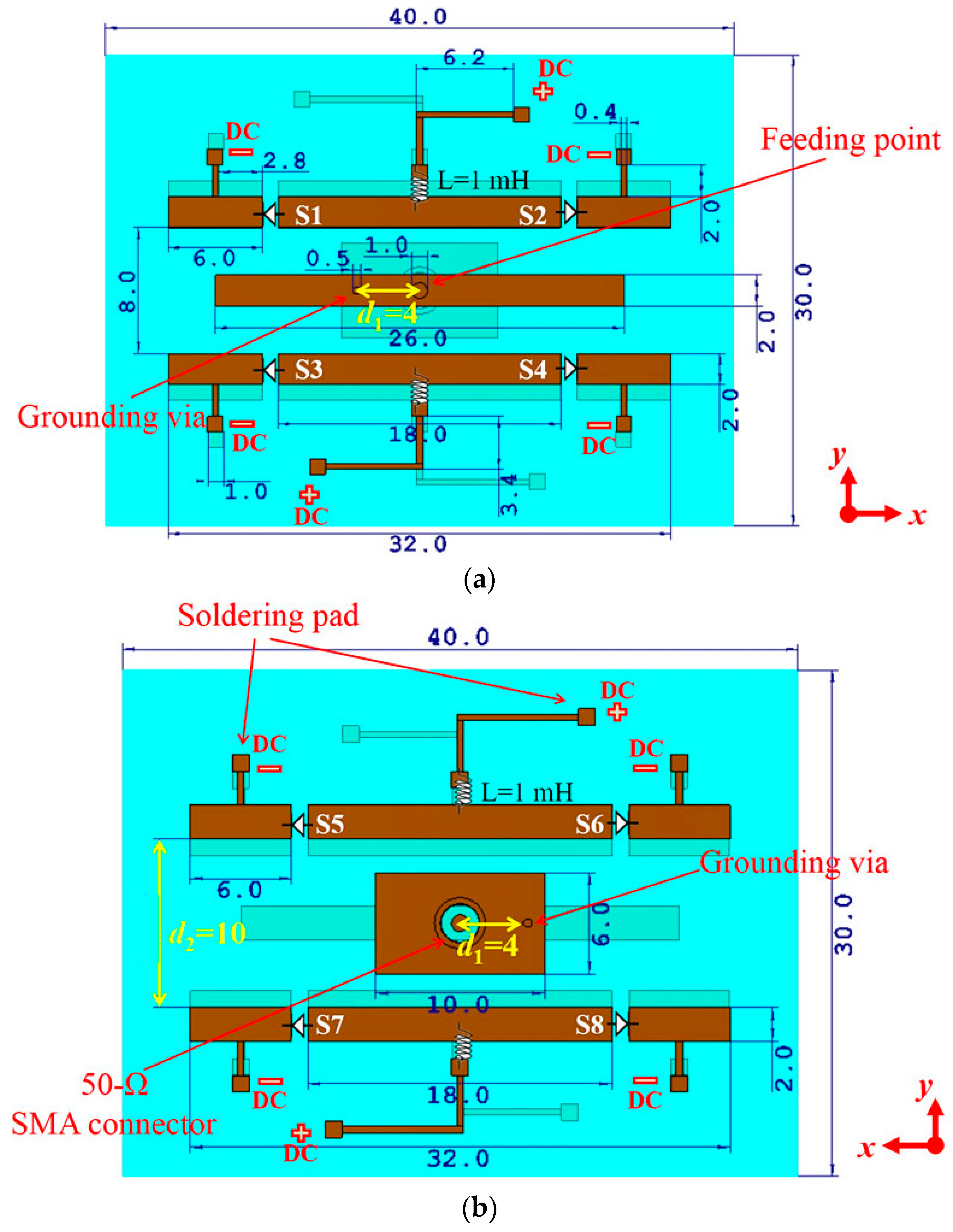
2. Antenna Design and Analysis
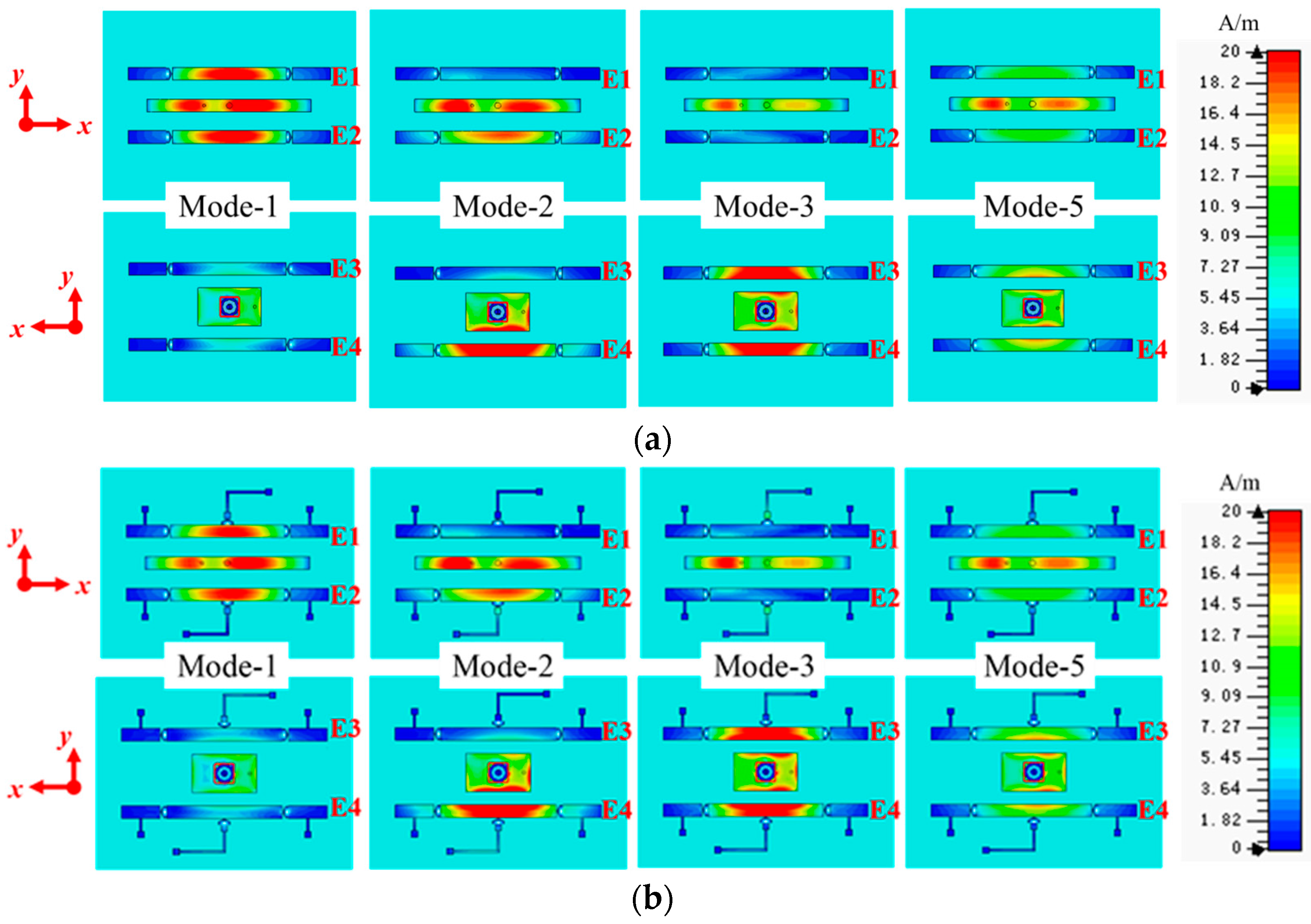
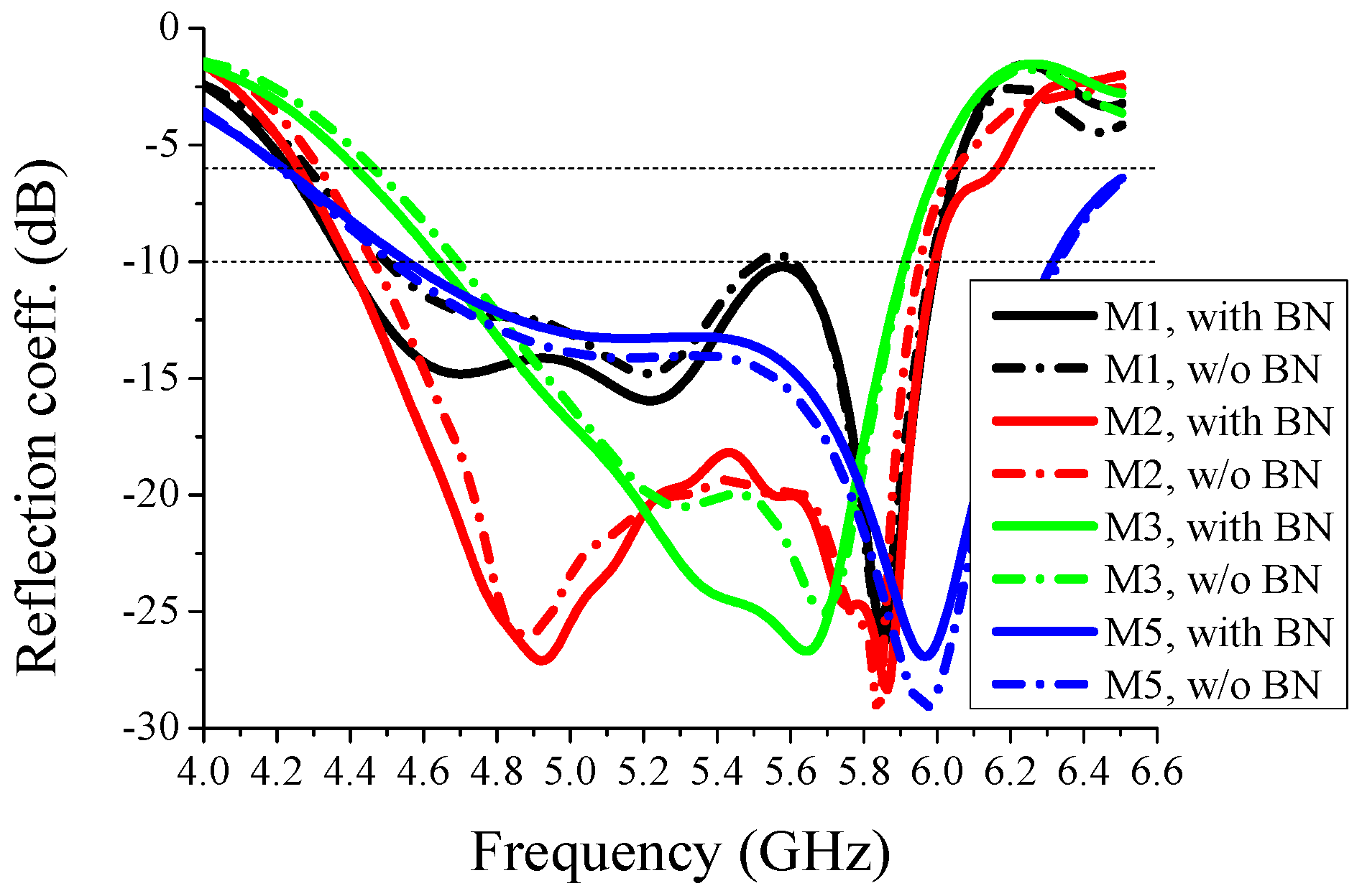
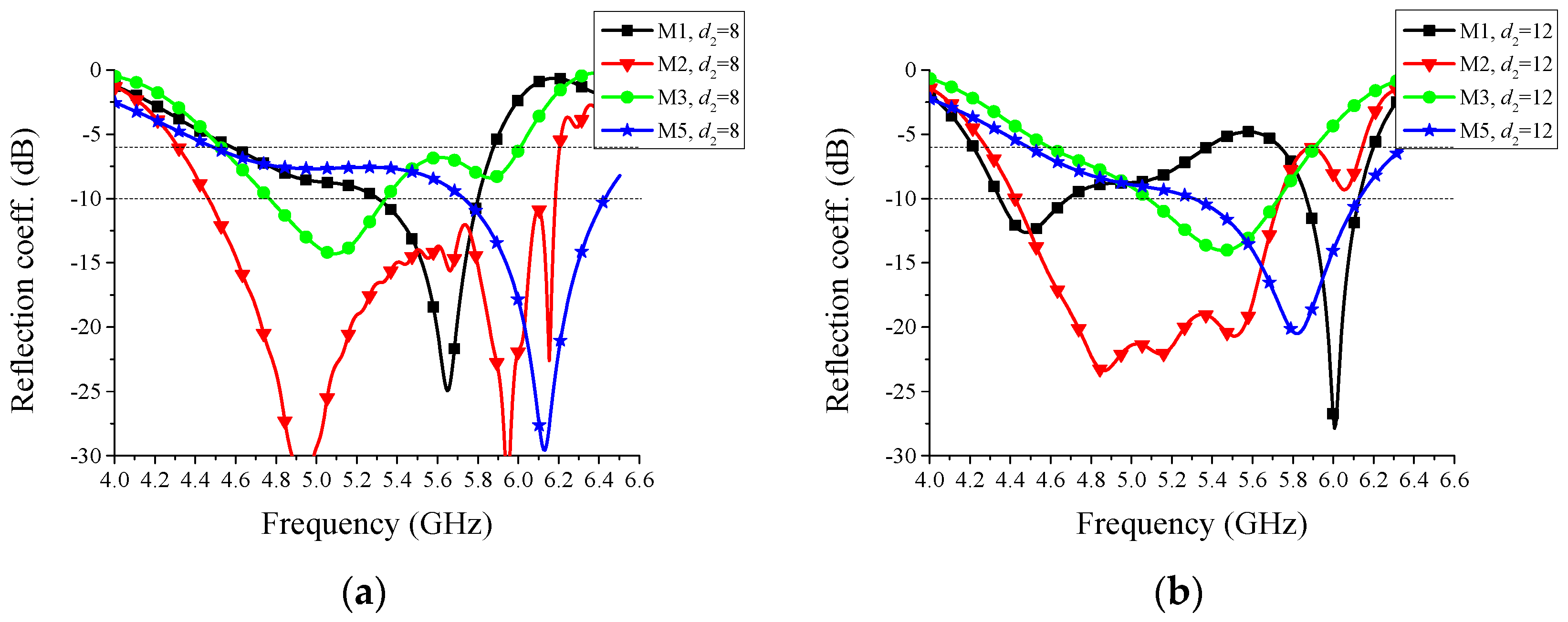
3. Results and Discussions
4. Conclusions
Acknowledgments
Author Contributions
Conflicts of Interest
References
- Sun, J.; Zhao, K.; Jiang, T. A multipoint correction method for environmental temperature changes in airborne double-antenna microwave radiometers. Sensors 2014, 14, 7820–7830. [Google Scholar] [CrossRef] [PubMed]
- Cao, H.; Jiang, F.; Liu, J.; Cai, W.; Tang, M.; Tan, X. A CSRR-fed SIW cavity-backed fractal patch antenna for wireless energy harvesting and communication. Sensors 2015, 15, 21196–21203. [Google Scholar] [CrossRef] [PubMed]
- Islam, M.T.; Islam, M.M.; Samsuzzaman, M.; Rashed, M.; Faruque, I.; Misran, N. A negative index metamaterial-inspired UWB antenna with an integration of complementary SRR and CLS unit cells for microwave imaging sensor applications. Sensors 2015, 15, 11601–11627. [Google Scholar] [CrossRef] [PubMed]
- Fujii, K.; Sakamoto, Y.; Wang, W.; Arie, H.; Schmitz, A.; Sugano, S. Hyperbolic positioning with antenna arrays and multi-channel pseudolite for indoor localization. Sensors 2015, 15, 25157–25175. [Google Scholar] [CrossRef] [PubMed]
- Lin, S.C.; Chen, K.C. Improving spectrum efficiency via in-network computations in cognitive radio sensor networks. IEEE Trans. Wirel. Commun. 2014, 13, 1222–1234. [Google Scholar] [CrossRef]
- Zubair, S.; Fisal, N. Reliable geographical forwarding in cognitive radio sensor networks using virtual clusters. Sensors 2014, 14, 8996–9026. [Google Scholar] [CrossRef] [PubMed]
- Costantine, J.; Tawk, Y.; Barbin, S.E.; Christodoulou, C.G. Reconfigurable antennas: design and applications. IEEE Proc. 2015, 103, 424–437. [Google Scholar] [CrossRef]
- Christodoulou, C.G.; Tawk, Y.; Lane, S.A.; Erwin, S.R. Reconfigurable antennas for wireless and space applications. IEEE Proc. 2012, 100, 2250–2261. [Google Scholar] [CrossRef]
- Hussain, R.; Sharawi, M.S. A cognitive radio reconfigurable MIMO and sensing antenna system. IEEE Antennas Wirel. Propag. Lett. 2014, 14, 257–260. [Google Scholar] [CrossRef]
- Lin, Y.C.; Yu, C.Y.; Li, C.M.; Liu, C.H.; Chen, J.P.; Chu, T.H. An ionic-polymer-metallic composite actuator for reconfigurable antennas in mobile devices. Sensors 2014, 14, 834–847. [Google Scholar] [CrossRef] [PubMed]
- Caratelli, D.; Massaro, A.; Cingolani, R.; Yarovoy, A.G. Accurate time-domain modeling of reconfigurable antenna sensors for non-invasive melanoma skin cancer detection. IEEE Sens. J. 2012, 12, 635–643. [Google Scholar] [CrossRef]
- Yuan, S.; Qiu, L.; Gao, S.; Tong, Y.; Yang, W. Providing self-healing ability for wireless sensor node by using reconfigurable hardware. Sensors 2012, 12, 14570–14591. [Google Scholar] [CrossRef] [PubMed]
- Burnett, D.C.; Smarr, B.L.; Mesri, S.M.; Kriegsfeld, L.J.; Pister, K.S. Reconfigurable, wearable sensors to enable long-duration circadian biomedical studies. In Proceedings of the 9th International Conference on Body Area Networks, Brussels, Belgium, 29 September–1 October 2014.
- Chen, C.A.; Chen, S.L.; Huang, H.Y.; Luo, C.H. An efficient micro control unit with a reconfigurable filter design for wireless body sensor networks (WBSNs). Sensors 2012, 12, 16211–16227. [Google Scholar] [CrossRef] [PubMed]
- Erfani, E.; Nourinia, J.; Ghobadi, C.; Niroo-Jazi, M.; Denidni, T.A. Design and implementation of an integrated UWB/reconfigurable-slot antenna for cognitive radio applications. IEEE Antennas Wirel. Propag. Lett. 2012, 11, 77–80. [Google Scholar] [CrossRef]
- Kim, Y.R.; Woo, J.M. Electrically tunable small microstrip antenna using interdigital plate loading for telemetry sensor applications. Electron. Lett. 2012, 48, 422–423. [Google Scholar] [CrossRef]
- Costantine, J.; Tawk, Y.; Christodoulou, C.G. Motion-activated reconfigurable and cognitive radio antenna systems. IEEE Antennas Wirel. Propag. Lett. 2013, 12, 1114–1117. [Google Scholar] [CrossRef]
- Qiao, Q.; Zhang, L.; Yang, F.; Yue, Z.; Elsherbeni, A.Z. Reconfigurable sensing antenna with novel HDPE-BST material for temperature monitoring. IEEE Antennas Wirel. Propag. Lett. 2013, 12, 1420–1423. [Google Scholar] [CrossRef]
- Yang, F.; Qiao, Q.; Virtanen, J.; Elsherbeni, A.Z.; Ukkonen, L.; Sydanheimo, L. Reconfigurable sensing antenna: a slotted patch design with temperature sensation. IEEE Antennas Wirel. Propag. Lett. 2012, 11, 632–635. [Google Scholar] [CrossRef]
- Catarinucci, L.; Guglielmi, S.; Colella, R.; Tarricone, L. Pattern-reconfigurable antennas and smart wake-up circuits to decrease power consumption in wsn nodes. IEEE Sens. J. 2014, 14, 4323–4324. [Google Scholar] [CrossRef]
- Wanuga, K.; Gulati, N.; Saarnisaari, H.; Dandekar, K.R. Online learning for spectrum sensing and reconfigurable antenna control. In Proceedings of 2014 9th International Conference on Cognitive Radio Oriented Wireless Networks and Communications, Oulu, Finland, 2–4 June 2014.
- Alaa, A.; Ismail, M.; Tawfik, M. Random aerial beamforming for underlay cognitive radio with exposed secondary users. IEEE Trans. Veh. Technol. 2016. [Google Scholar] [CrossRef]
- Hakkarainen, A.; Werner, J.; Gulati, N.; Patron, D. Reconfigurable antenna based DOA estimation and localization in cognitive radios: Low complexity algorithms and practical measurements. In Proceedings of the 2014 9th International Conference on Cognitive Radio Oriented Wireless Networks and Communications, Oulu, Finland, 2–4 June 2014.
- Werner, J.; Wang, J.; Hakkarainen, A.; Cabric, D. Performance and cramer-rao bounds for DOA/RSS estimation and transmitter localization using sectorized antennas. IEEE Trans. Veh. Technol. 2016. [Google Scholar] [CrossRef]
- Guzmán-Quirós, R.; Martínez-Sala, A.; Gómez-Tornero, J.L.; García-Haro, J. Integration of directional antennas in an RSS fingerprinting-based indoor localization system. Sensors 2016, 16, 4–26. [Google Scholar] [CrossRef] [PubMed]
- Tawk, Y.; Costantine, J.; Avery, K.; Christodoulou, C.G. Implementation of a cognitive radio front-end using rotatable controlled reconfigurable antennas. IEEE Trans. Antennas Propag. 2011, 59, 1773–1778. [Google Scholar] [CrossRef]
- Qin, P.Y.; Guo, Y.J.; Weily, A.R.; Liang, C.H. A pattern reconfigurable U-slot antenna and its applications in MIMO systems. IEEE Trans. Antennas Propag. 2012, 60, 516–528. [Google Scholar] [CrossRef]
- Sarrazin, J.; Mahé, Y.; Avrillon, S.; Toutain, S. Pattern reconfigurable cubic antenna. IEEE Trans. Antennas Propag. 2009, 57, 310–317. [Google Scholar] [CrossRef] [Green Version]
- Cai, X.; Wang, A.G.; Ma, N.; Leng, W. A novel planar parasitic array antenna with reconfigurable azimuth pattern. IEEE Antennas Wirel. Propag. Lett. 2012, 11, 1186–1189. [Google Scholar]
- Lai, M.I.; Wu, T.Y.; Hsieh, J.C.; Wang, C.H. Compact switched-beam antenna employing a four-element slot antenna array for digital home applications. IEEE Trans. Antennas Propag. 2008, 56, 2929–2936. [Google Scholar] [CrossRef]
- Eom, S.H.; Seo, Y.; Lim, S. Pattern switchable antenna system using inkjet-printed directional bow-tie for bi-direction sensing applications. Sensors 2015, 15, 31171–31179. [Google Scholar] [CrossRef] [PubMed]
- Ding, X.; Wang, B.Z. A novel wideband antenna with reconfigurable broadside and endfire patterns. IEEE Antennas Wirel. Propag. Lett. 2013, 12, 995–998. [Google Scholar] [CrossRef]
- Li, M.; Xiao, S.Q.; Wang, Z.; Wang, B.Z. Compact surface-wave assisted beam-steerable antenna based on HIS. IEEE Trans. Antennas Propag. 2014, 62, 3511–3519. [Google Scholar] [CrossRef]
- Qin, P.Y.; Guo, Y.J.; Ding, C. A beam switching quasi-yagi dipole antenna. IEEE Trans. Antennas Propag. 2013, 61, 4891–4899. [Google Scholar] [CrossRef]
- Gu, C.; Gao, S.; Liu, H.; Luo, Q. Compact smart antenna with electronic beam-switching and reconfigurable polarizations. IEEE Trans. Antennas Propag. 2015, 63, 5325–5333. [Google Scholar]
- Rodrigo, D.; Cetiner, B.A.; Jofre, L. Frequency, radiation pattern and polarization reconfigurable antenna using a parasitic pixel layer. IEEE Trans. Antennas Propag. 2014, 62, 3422–3427. [Google Scholar] [CrossRef]
- Ji, L.Y.; Guo, Y.J.; Qin, P.Y.; Gong, S.X. A reconfigurable partially reflective surface (PRS) antenna for beam steering. IEEE Trans. Antennas Propag. 2015, 63, 2387–2395. [Google Scholar] [CrossRef]
- Zhang, L.; Wu, Q.; Denidni, T.A. Electronically radiation pattern steerable antennas using active frequency selective surfaces. IEEE Trans. Antennas Propag. 2013, 61, 6000–6007. [Google Scholar] [CrossRef]
- D'Hoe, K.; Ottoy, G.; Goemaere, J.P.; Strycker, L. Indoor room location estimation. Adv. Electr. Comput. Eng. 2008, 8, 78–81. [Google Scholar] [CrossRef]
- Chiu, Y.M.; Wang, K.; Jan, R.H.; Hu, Y.J.; Ku, T.H. An efficient room-based indoor localization scheme for wireless sensor networks. In Proceedings of the 5th Workshop on Wireless Ad Hoc and Sensor Networks, Hsinchu, China, 10–11 September 2009.
- Lo, C.-C.; Chen, C.-C.; Tseng, Y.-C.; Chiang, J.-C.; Feng, K.-C.; Kuo, L.-C.; Wang, Y.-C. A room-based localization system using wireless triggers and pattern matching techniques. In Proceedings of the IEEE VTS Asia Pacific Wireless Communications Symposium, Kyoto, Japan, 23–24 August 2012.
- Kang, W.S.; Park, J.A.; Yoon, Y.J. Simple reconfigurable antenna with radiation pattern. Electron. Lett. 2008, 44, 182–183. [Google Scholar] [CrossRef]
- Hwang, K.S.; Ahn, J.; Kim, K.J.; Yoon, H.K.; Yoon, Y.J. Pattern reconfigurable antenna for a wireless sensor network sink node. In Proceedings of the 2010 Asia-Pacific Microwave Conference Proceedings, Yokohama, Japan, 7–10 December 2010.
- Kim, K.; Hwang, K.; Ahn, J.; Yoon, Y. Pattern reconfigurable antenna for wireless sensor network system. Electron. Lett. 2012, 48, 984–985. [Google Scholar] [CrossRef]
- Patron, D.; Piazza, D.; Dandekar, K.R. Wideband planar antenna with reconfigurable omnidirectional and directional radiation patterns. Electron. Lett. 2013, 49, 516–518. [Google Scholar] [CrossRef]
- Patron, D.; Daryoush, A.S.; Dandekar, K.R. Optical control of reconfigurable antennas and application to a novel pattern-reconfigurable planar design. IEEE J. Lightw. Technol. 2014, 32, 3394–3402. [Google Scholar] [CrossRef]
- Bai, Y.Y.; Xiao, S.; Liu, C.; Shuai, X.; Wang, B.Z. Design of pattern reconfigurable antennas based on a two—element dipole array model. IEEE Trans. Antennas Propag. 2013, 61, 4867–4871. [Google Scholar] [CrossRef]
- Row, J.S.; Tsai, C.W. Pattern reconfigurable antenna array with circular polarization. IEEE Trans. Antennas Propag. 2016, 64, 1525–1530. [Google Scholar] [CrossRef]
- Tawk, Y.; Christodoulou, C.G.; Costantine, J.; Barbin, S.E. A frequency and radiation pattern reconfigurable antenna system with sensing capabilities for cognitive radio. In Proceedings of the 2012 IEEE Antennas and Propagation Society International Symposium, Chicago, IL, USA, 8–14 July 2012.
- Ren, J.; Yang, X.; Yin, J.; Yin, Y. A novel antenna with reconfigurable patterns using H-shaped structures. IEEE Antennas Wirel. Propag. Lett. 2015, 14, 915–918. [Google Scholar] [CrossRef]
- Aboufoul, T.; Parini, C.; Chen, X.; Alomainy, A. Pattern-reconfigurable planar circular ultra-wideband monopole antenna. IEEE Trans. Antennas Propag. 2013, 61, 4973–4980. [Google Scholar] [CrossRef]
- Partington, K.C.; Flach, J.D.; Barber, D.; Isleifson, D.; Meadows, P.J.; Verlaan, P. Dual-polarization C-band radar observations of sea ice in the amundsen gulf. IEEE Trans. Geosci. Remote Sens. 2010, 48, 2685–2691. [Google Scholar] [CrossRef]
- Jeon, S.S.; Miyamoto, R.Y.; Wang, Y.; Qian, Y.; Itoh, T. Direction-of-arrival estimation using a single-card C-band receiver array. In Proceedings of the 2000 Asia-Pacific Microwave Conference, Sydney, Australia, 3–6 December 2000.
- Scarchilli, G.; Goroucci, E.; Chandrasekar, V.; Seliga, T.A. Rainfall estimation using polarimetric techniques at c-band frequencies. J. Appl. Meteorol. 1993, 32, 1150–1160. [Google Scholar] [CrossRef]
- MACOM/PIN Switch and Attenuator Diodes/AlGaA PIN Diode/MA4AGBLP912. Available online: https://www.macom.com/products/product-detail?partNumber=MA4AGBLP912 (accessed on 5 June 2015).
- Caratelli, D.; Cicchetti, R.; Bit-Babik, G.; Faraone, A. Circuit model and near-field behavior of a novel patch antenna for wwlan applications. Microw. Opt. Technol. Lett. 2007, 49, 97–100. [Google Scholar] [CrossRef]
- Balanis, C.A. Antenna Theory, Analysis and Design, 2nd ed.; Wiley: New York, NY, USA, 1997. [Google Scholar]


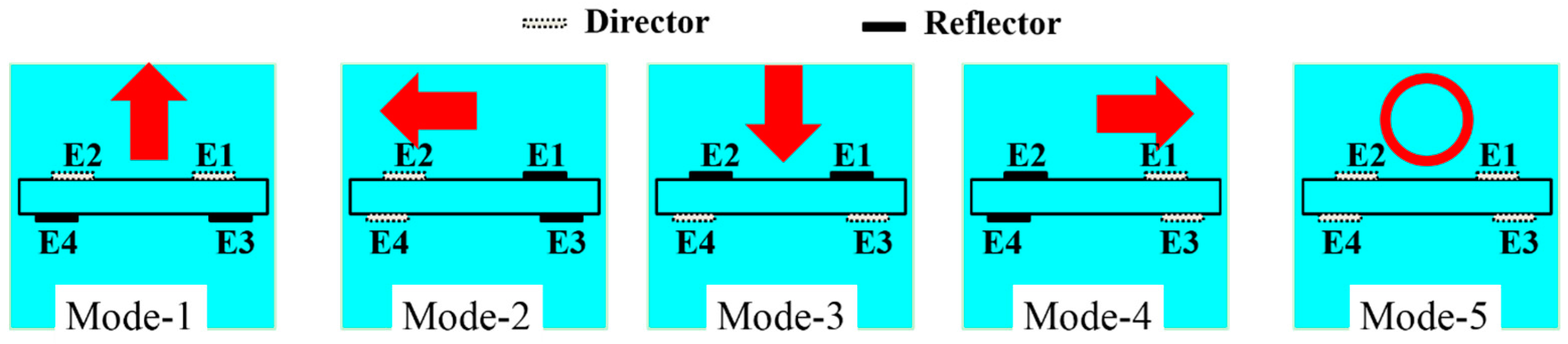
| Mode-1 | Mode-2 | Mode-3 | Mode-4 | Mode-5 | |
|---|---|---|---|---|---|
| S1&S2 | OFF | ON | ON | OFF | OFF |
| S3&S4 | OFF | OFF | ON | ON | OFF |
| S5&S6 | ON | ON | OFF | OFF | OFF |
| S7&S8 | ON | OFF | OFF | ON | OFF |
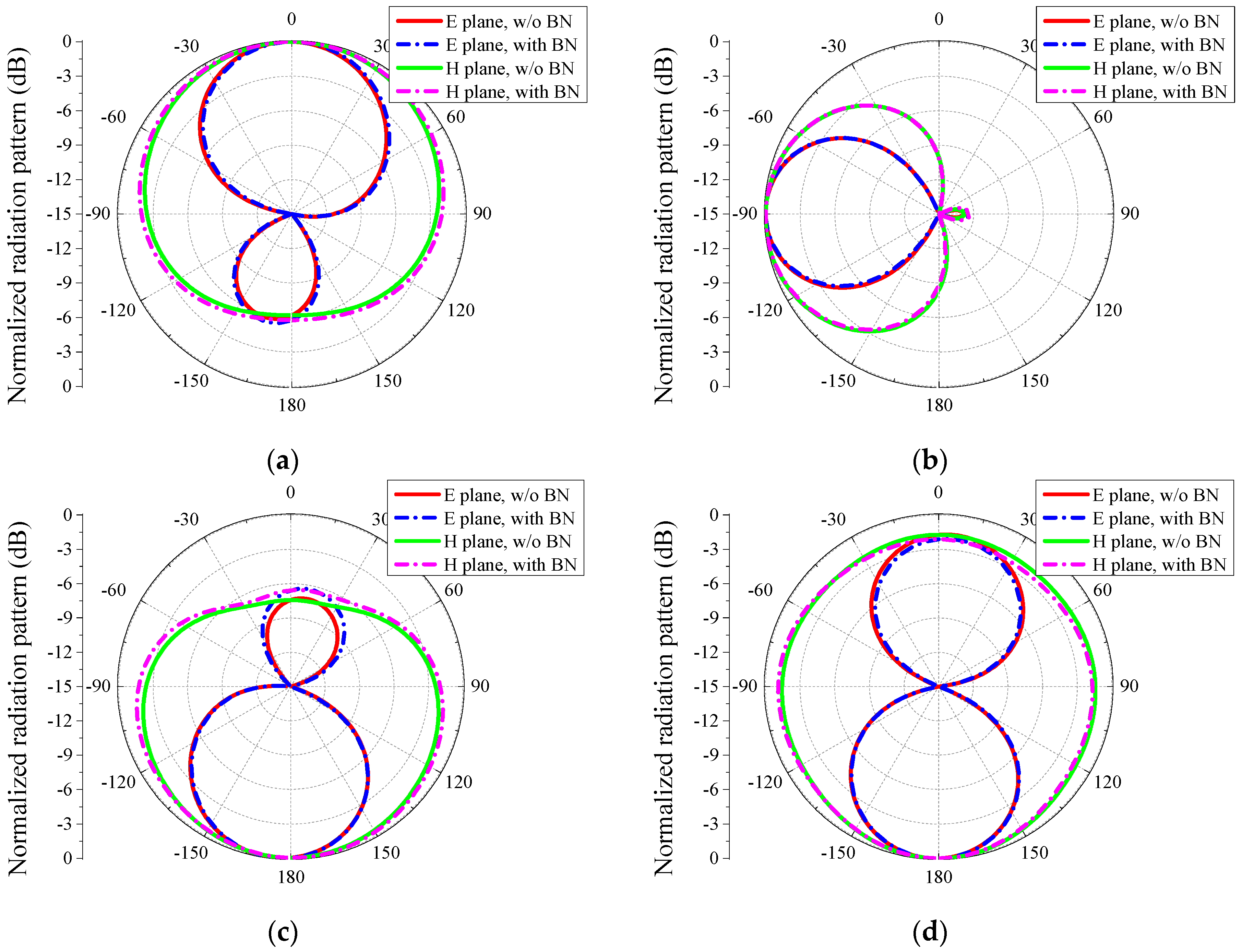
| Main Beam Direction | Half-Power Beamwidth | Front-to-Back Ratio | |||||
|---|---|---|---|---|---|---|---|
| E plane | H plane | E plane | H plane | E plane | H plane | ||
| Mode-1 | Sim. | 8° | 0° | 84° | 220° | 5.5 dB | 6 dB |
| Meas. | 15° | 1° | 90° | 192° | 8 dB | 9 dB | |
| Mode-2 | Sim. | −90° | −90° | 61° | 110° | 13 dB | 12 dB |
| Meas. | −89° | −90° | 59° | 107° | 7 dB | 7 dB | |
| Mode-3 | Sim. | −187 | −180° | 75° | 215° | 6.5 dB | 6.5 dB |
| Meas. | −190° | −179° | 80° | 217° | 5.5 dB | 5.5 dB | |
| Mode-5 | Sim. | – | – | – | 360° | – | – |
| Meas. | – | – | – | 360° | – | – | |
| Reference | Basic Method | Impedance Bandwidth | Blindness Range | Peak Gain | Beamwidth | Volume (λ3) | Area (λ2) | Structure Complexity |
|---|---|---|---|---|---|---|---|---|
| [42] | MDS | 6.5% | Yes | 5.3 dB | ~180° | 0.002 | 0.24 | No |
| [44] | MDS | 3.7% | Yes | 6.6 dB | ~90° | 0.009 | 0.54 | Yes |
| [46] | RAS | 8.2% | Yes | 3.6 dB | 65°/65° | 0.006 | 0.45 | No |
| [47] | RAS | 6.6% | Yes | 4 dB | 59°/65° | 0.007 | 0.08 | Yes |
| [48] | RAS | 19% | No | 7.1 dB | 140°/140° | 3.648 | 2.16 | Yes |
| [50] | MPES | 16% | Yes | 6.4 dB | ~120° | 0.259 | 0.39 | Yes |
| [51] | MPES | 127% | Yes | 2.1 dB | ~150° | 0.015 | 0.45 | No |
| Proposed | MPES | 24% | No | 5.9 dB | 107°/217° | 0.007 | 0.37 | No |
© 2016 by the authors; licensee MDPI, Basel, Switzerland. This article is an open access article distributed under the terms and conditions of the Creative Commons Attribution (CC-BY) license (http://creativecommons.org/licenses/by/4.0/).
Share and Cite
Wang, R.; Wang, B.-Z.; Huang, W.-Y.; Ding, X. Compact Reconfigurable Antenna with an Omnidirectional Pattern and Four Directional Patterns for Wireless Sensor Systems. Sensors 2016, 16, 552. https://doi.org/10.3390/s16040552
Wang R, Wang B-Z, Huang W-Y, Ding X. Compact Reconfigurable Antenna with an Omnidirectional Pattern and Four Directional Patterns for Wireless Sensor Systems. Sensors. 2016; 16(4):552. https://doi.org/10.3390/s16040552
Chicago/Turabian StyleWang, Ren, Bing-Zhong Wang, Wei-Ying Huang, and Xiao Ding. 2016. "Compact Reconfigurable Antenna with an Omnidirectional Pattern and Four Directional Patterns for Wireless Sensor Systems" Sensors 16, no. 4: 552. https://doi.org/10.3390/s16040552