
Optical Riblet Sensor: Beam Parameter Requirements for the Probing Laser Source

Abstract
:
1. Introduction
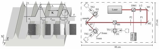
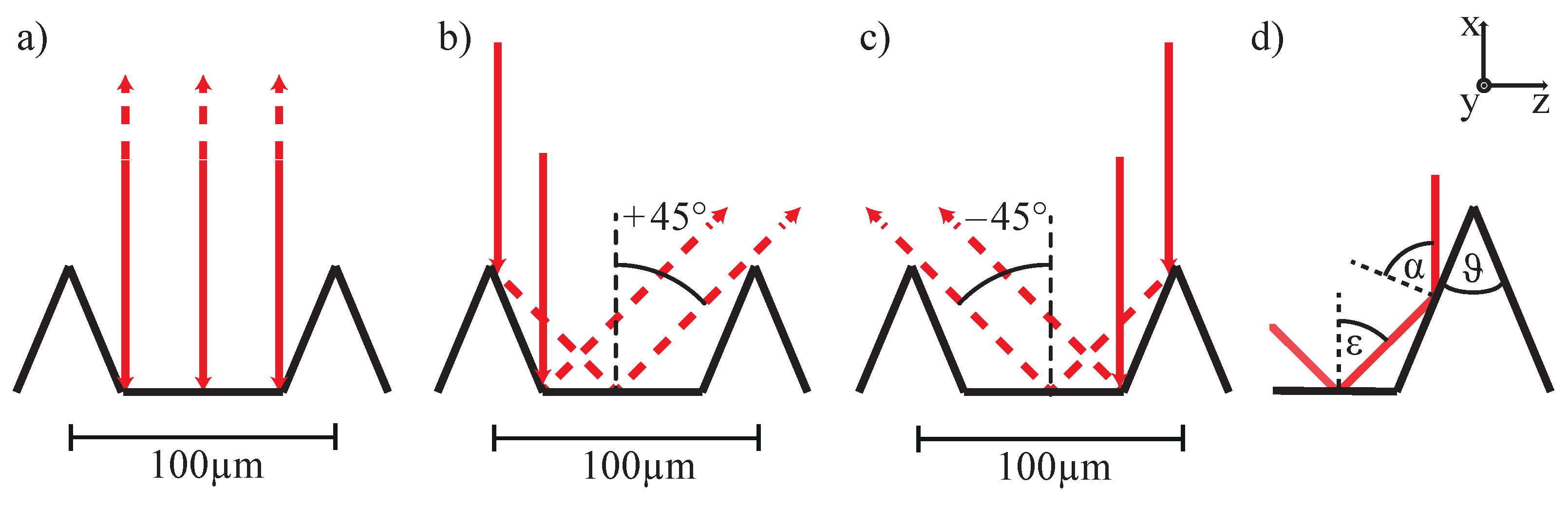
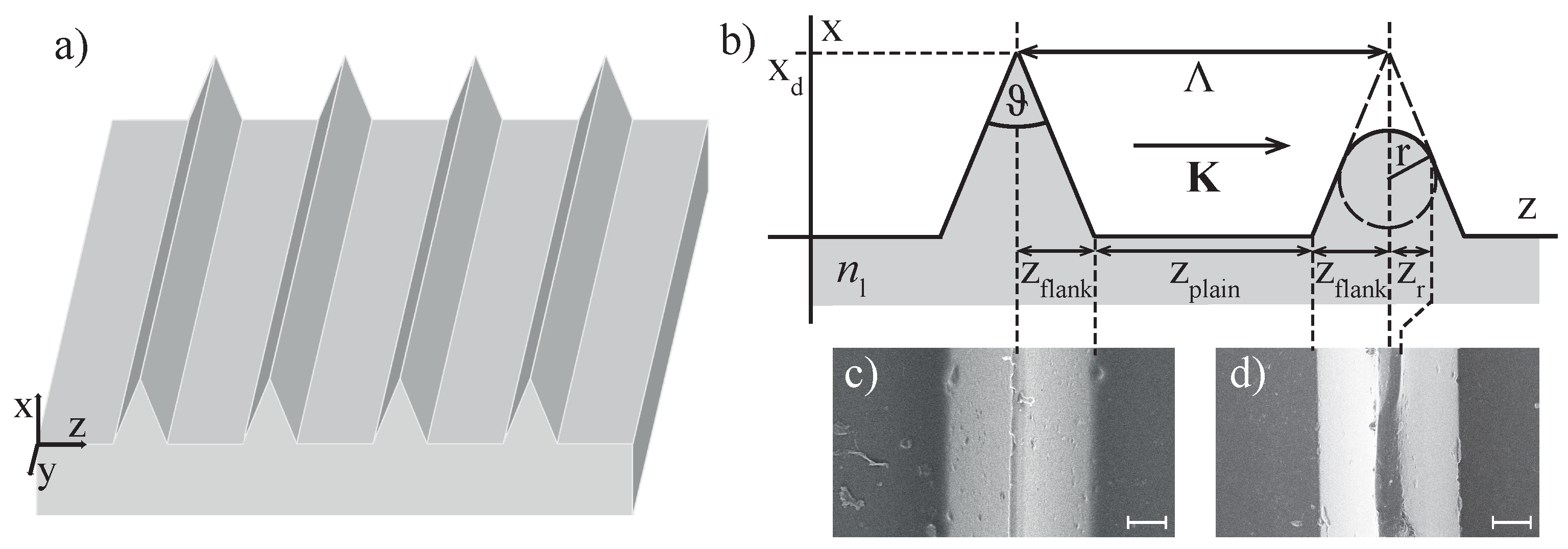
2. Riblet Samples
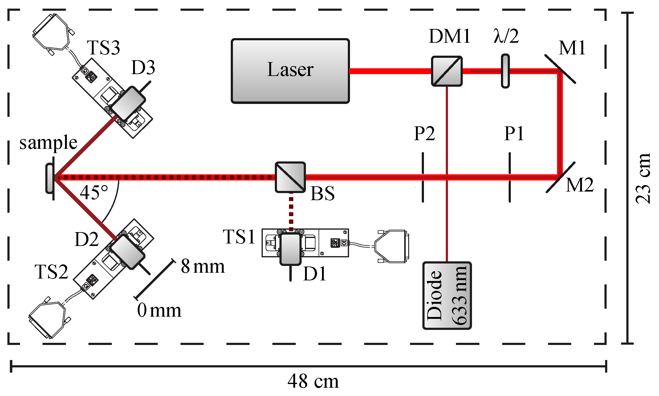
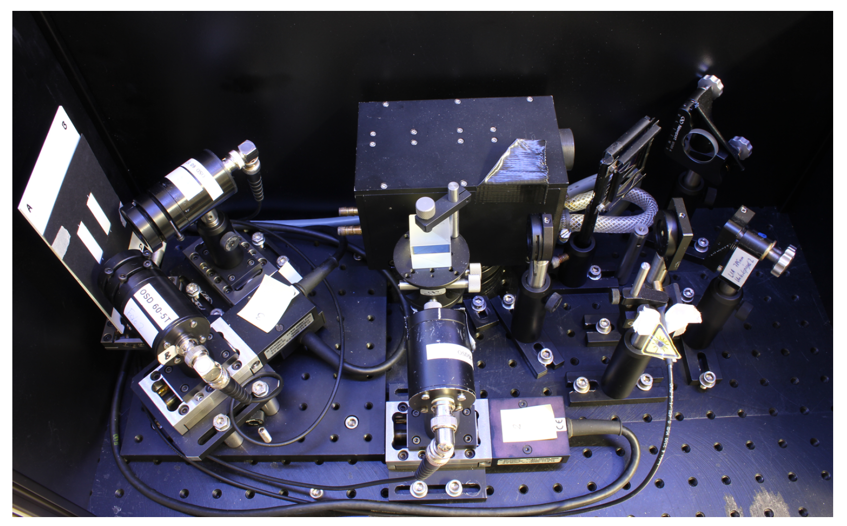
3. Riblet Sensor
4. Riblet Sensor Measures without Reference Sample
5. Experimental Section: Impact of Beam Parameters on SNR
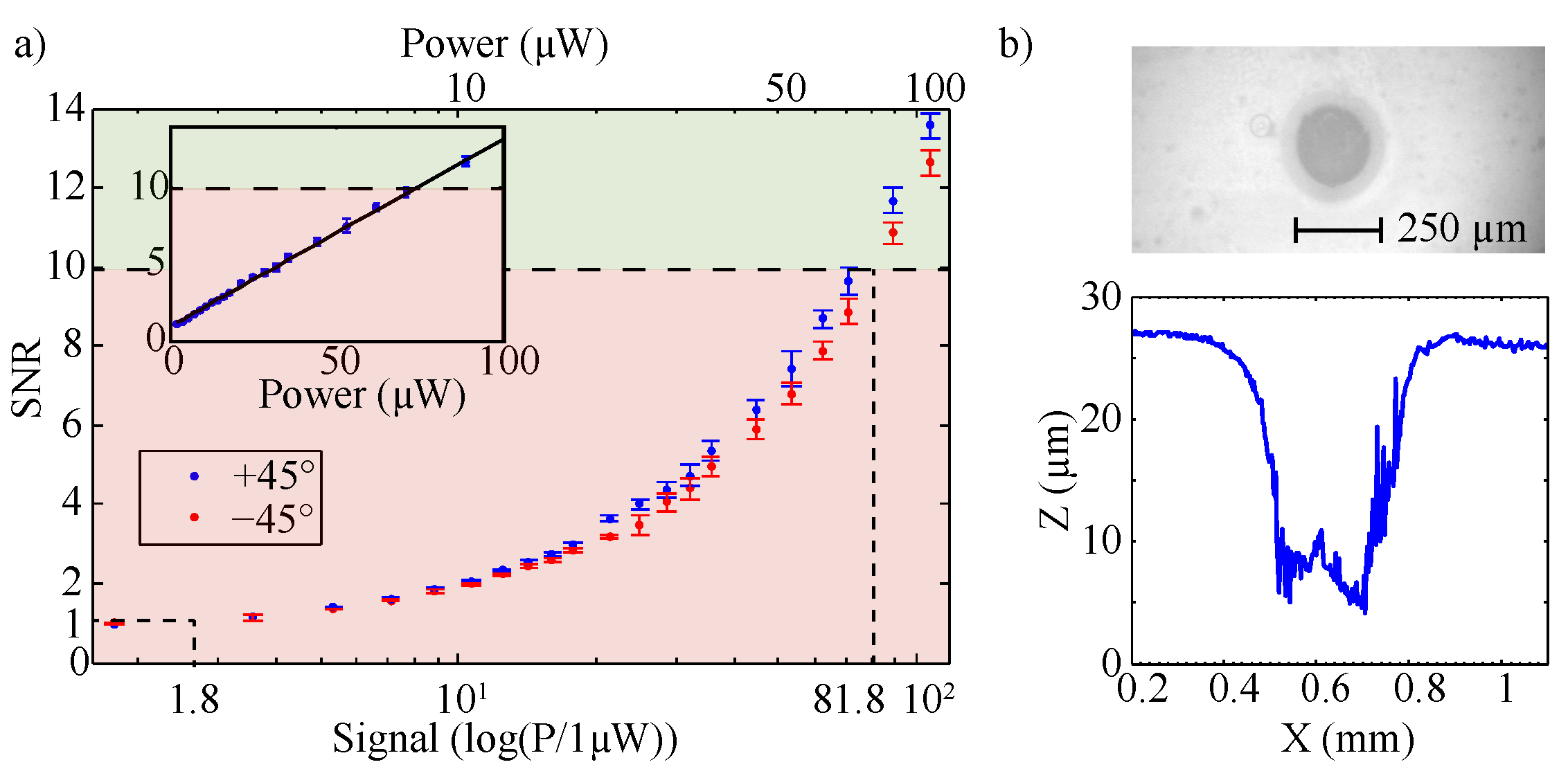
5.1. Laser Power
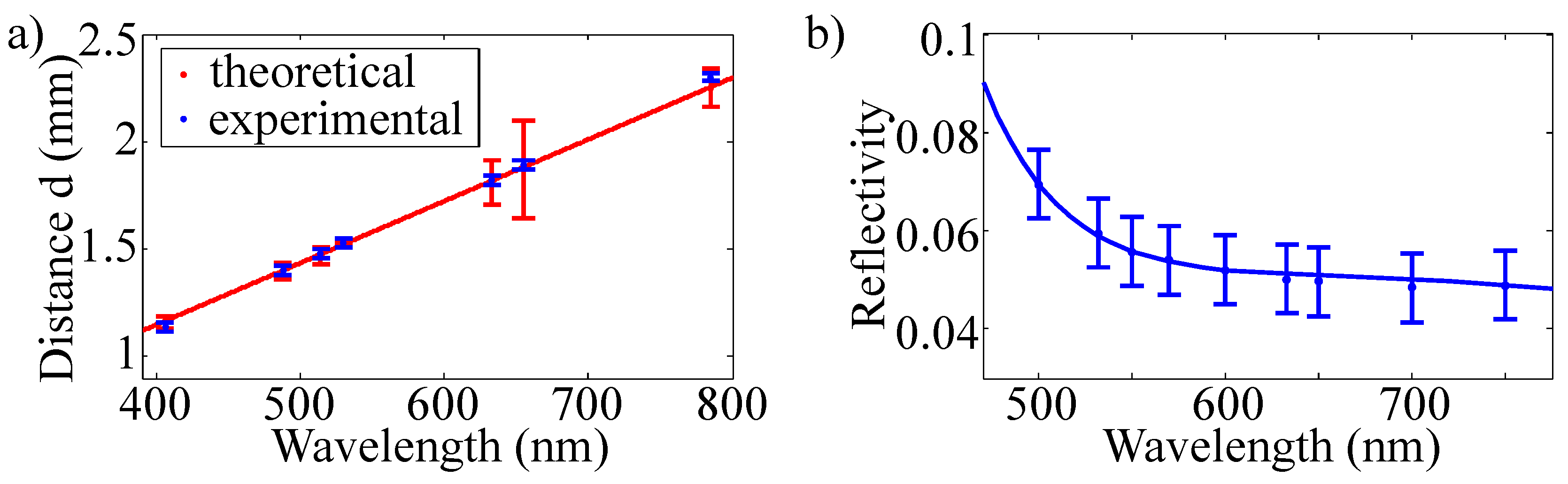
5.2. Wavelength and Beam Divergence
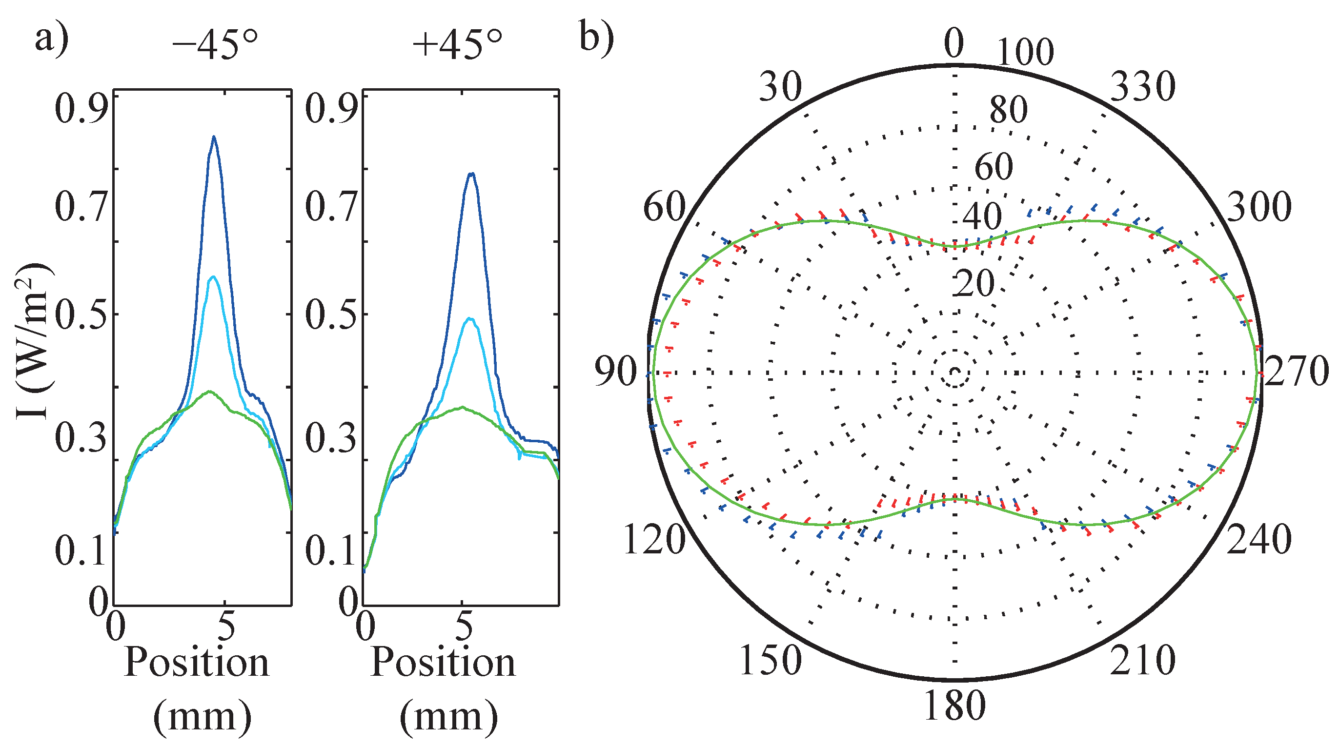
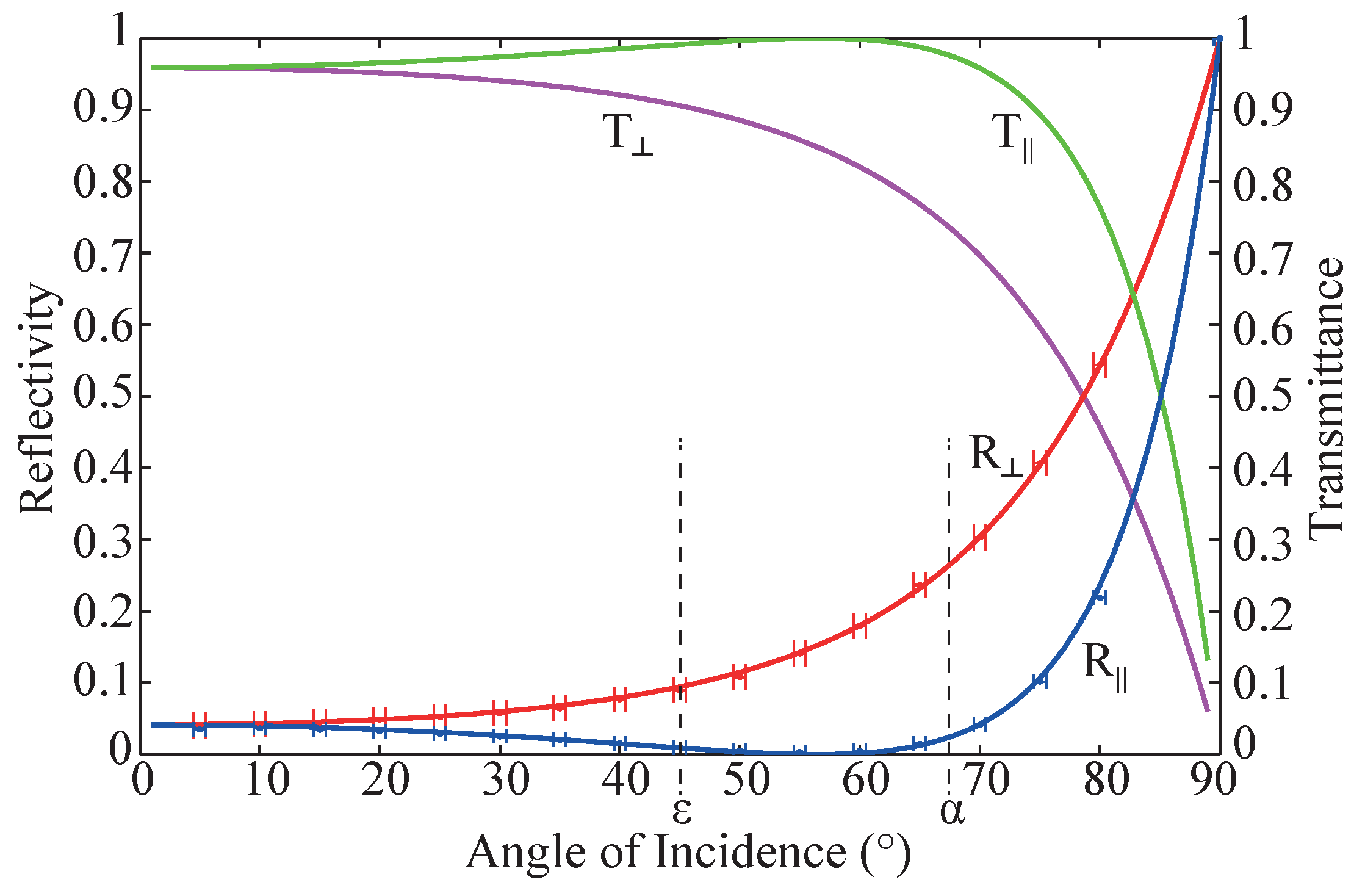
5.3. Polarization
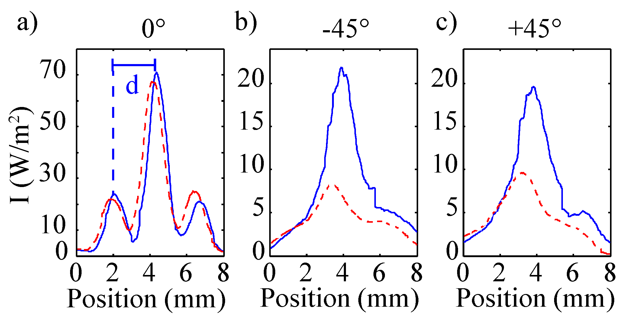
5.4. Data Scans
6. Discussion
7. Conclusions
Acknowledgments
Author Contributions
Conflicts of Interest
References
- Bechert, D.W.; Bruse, M.; Hage, W.; van der Hoeven, J.G.T.; Hoppe, G. Experiments on drag-reducing surfaces and their optimization with an adjustable geometry. J. Fluid Mech. 1997, 338, 59–87. [Google Scholar] [CrossRef]
- Bruse, M.; Bechert, D.; van der Hoeven, J.T.; Hage, W.; Hoppe, G. Experiments with conventional and with novel adjustable drag-reducing surfaces. In Proceedings of the International Conference on Near-Wall Turbulent Flows, Tempe, AZ, USA, 15–18 March 1993; pp. 719–738.
- Walsh, M. Effect of Detailed Surface Geometry on Riblet Drag Reduction Performance. J. Aircr. 1990, 27, 572–573. [Google Scholar] [CrossRef]
- Bechert, D.W.; Bruse, M.; Hage, W.; Meyer, R. Fluid Mechanics of Biological Surfaces and their Technological Application. Naturwissenschaften 2000, 87, 157–171. [Google Scholar] [CrossRef] [PubMed]
- Dean, B.; Bhushan, B. Shark-skin surfaces for fluid-drag reduction in turbulent flow: A review. Philos. Trans. Royal Soc. Lond. A Math. Phys. Eng. Sci. 2010, 368, 4775–4806. [Google Scholar] [CrossRef] [PubMed]
- Lee, S.J.; Lee, S.H. Flow field analysis of a turbulent boundary layer over a riblet surface. Exp. Fluids 2001, 30, 153–166. [Google Scholar] [CrossRef]
- García-Mayoral, R.; Jiménez, J. Drag reduction by riblets. Philos. Trans. Royal Soc. Lond. A Math. Phys. Eng. Sci. 2011, 369, 1412–1427. [Google Scholar] [CrossRef] [PubMed]
- Imlau, M.; Bruening, H.; Voit, K.M.; Tschentscher, J.; Dieckmann, V. Riblet Sensor-Light Scattering on Micro Structured Surface Coatings. Available online: http://arxiv.org/abs/1601.04694 (accessed on 29 March 2016).
- Bixler, G.D.; Bhushan, B. Bioinspired micro/nanostructured surfaces for oil drag reduction in closed channel flow. Soft Matter 2013, 9, 1620–1635. [Google Scholar] [CrossRef]
- Bixler, G.D.; Bhushan, B. Fluid Drag Reduction with Shark-Skin Riblet Inspired Microstructured Surfaces. Adv. Funct. Mater. 2013, 23, 4507–4528. [Google Scholar] [CrossRef]
- Stenzel, V.; Wilke, Y.; Hage, W. Drag-reducing paints for the reduction of fuel consumption in aviation and shipping. Prog. Org. Coat. 2011, 70, 224–229. [Google Scholar] [CrossRef]
- Denkena, B.; de Leon, L.; Wang, B. Grinding of microstructured functional surfaces: A novel strategy for dressing of microprofiles. Prod. Eng. 2009, 3, 41–48. [Google Scholar] [CrossRef]
- Han, X.; Zhang, D. Study on the micro-replication of shark skin. Sci. Chin. Series E Technol. Sci. 2008, 51, 890–896. [Google Scholar] [CrossRef]
- Hirt, G.; Thome, M. Large area rolling of functional metallic micro structures. Prod. Eng. 2007, 1, 351–356. [Google Scholar] [CrossRef]
- Klocke, F.; Feldhaus, B.; Mader, S. Development of an incremental rolling process for the production of defined riblet surface structures. Prod. Eng. 2007, 1, 233–237. [Google Scholar] [CrossRef]
- Marentic, F.; Morris, T. Drag Reduction Article. U.S. Patent 5,133,516, 28 July 1992. [Google Scholar]
- Meyer, U.; Markus, S.; Dieckhoff, S. Device for Testing the Quality of Microstructurization. U.S. Patent 8,842,271, 23 September 2014. [Google Scholar]


| Laser System | Power (mW) | Wavelength (nm) | Beam Divergence (rad) | Laser Safety Class |
|---|---|---|---|---|
| InGaN laser diode | 60 | 406 | 5.21(44) | 3B |
| frequency-doubled OPSL | 2000 | 488 | 4.65(39) | 4 |
| Ar-ion laser | 1400 | 488 | 5.82(49) | 4 |
| Ar-ion laser | 2000 | 514 | 6.66(54) | 4 |
| frequency doubled Nd:YVO | 1 | 530 | 5.26(29) | 2 |
| He-Ne laser | 3 | 632.8 | 1.40(23) | 3B |
| AlGaInP laser diode | 5 | 655 | 1.00(69) | 3B |
| GaAs laser diode | 40 | 785 | 1.20(19) | 3B |
| Parameter | Value |
|---|---|
| riblet periodicity Λ | 100 µm |
| riblet height h | 50 µm |
| reflection angle α | 67.5 |
| reflection angle ε | 45 |
| reflectivity R(0) | 0.041 |
| reflectivity R(45) | 0.094 |
| reflectivity R(67.5) | 0.265 |
| z | 0.21 |
| z | 0.59 |
| 0.1778 |
© 2016 by the authors; licensee MDPI, Basel, Switzerland. This article is an open access article distributed under the terms and conditions of the Creative Commons by Attribution (CC-BY) license (http://creativecommons.org/licenses/by/4.0/).
Share and Cite
Tschentscher, J.; Hochheim, S.; Brüning, H.; Brune, K.; Voit, K.-M.; Imlau, M. Optical Riblet Sensor: Beam Parameter Requirements for the Probing Laser Source. Sensors 2016, 16, 458. https://doi.org/10.3390/s16040458
Tschentscher J, Hochheim S, Brüning H, Brune K, Voit K-M, Imlau M. Optical Riblet Sensor: Beam Parameter Requirements for the Probing Laser Source. Sensors. 2016; 16(4):458. https://doi.org/10.3390/s16040458
Chicago/Turabian StyleTschentscher, Juliane, Sven Hochheim, Hauke Brüning, Kai Brune, Kay-Michael Voit, and Mirco Imlau. 2016. "Optical Riblet Sensor: Beam Parameter Requirements for the Probing Laser Source" Sensors 16, no. 4: 458. https://doi.org/10.3390/s16040458