1. Introduction
Recently, problems have been caused by mechanical vibrations [
1,
2]. Passengers often feel uncomfortable, especially in automobiles by a frame vibration that is generated by an engine. In order to solve the problem, active vibration control devices have been developed [
3,
4,
5,
6,
7]. In these devices, many electromagnetic linear oscillatory actuators are used because of their high controllability. However, the electric power of these actuators is relatively high. Therefore, a high thrust and large vibration due to small currents have been required at a wide drive frequency range. In previous studies, actuators with improved magnetic circuits have been proposed [
8,
9]. However, the effectiveness of the improved magnetic circuit is still low for the high thrust and vibration characteristics. Here, we have developed an actuator using a regenerative energy, as shown in
Figure 1 [
10]. Furthermore, the actuator is verified to realize variable characteristics under high thrust and large vibration by changing the coil connection, as shown in
Figure 2. However, the previous actuator has difficulty manufacturing because a mover is sandwiched by two stators. In this paper, a new and simple actuator that has variable characteristics for high thrust and large vibration is proposed [
11]. The operational principle is described, and its characteristics are computed using finite element analysis. Finally, the effectiveness of the proposed actuator is discussed.
2. Proposed Actuator
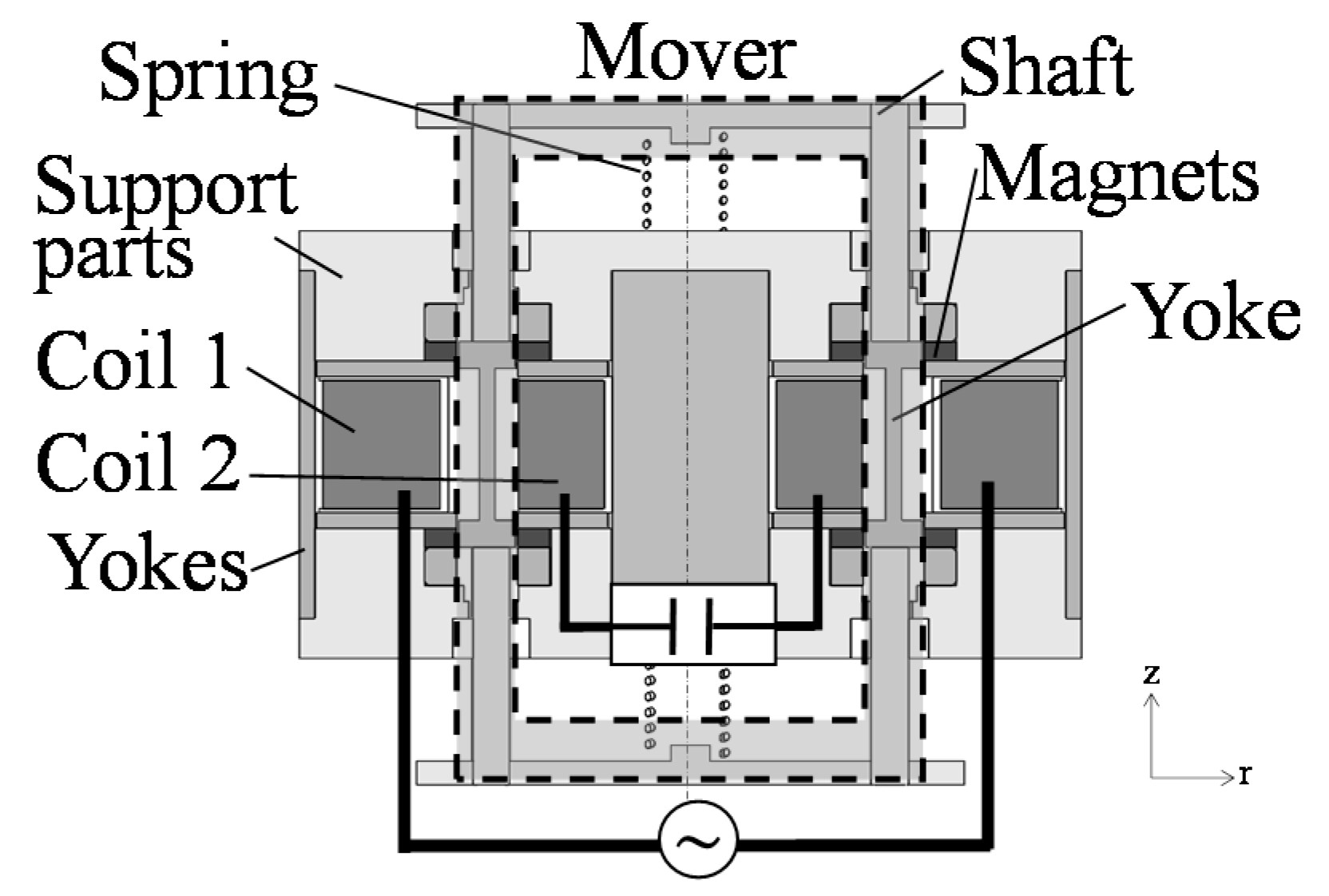
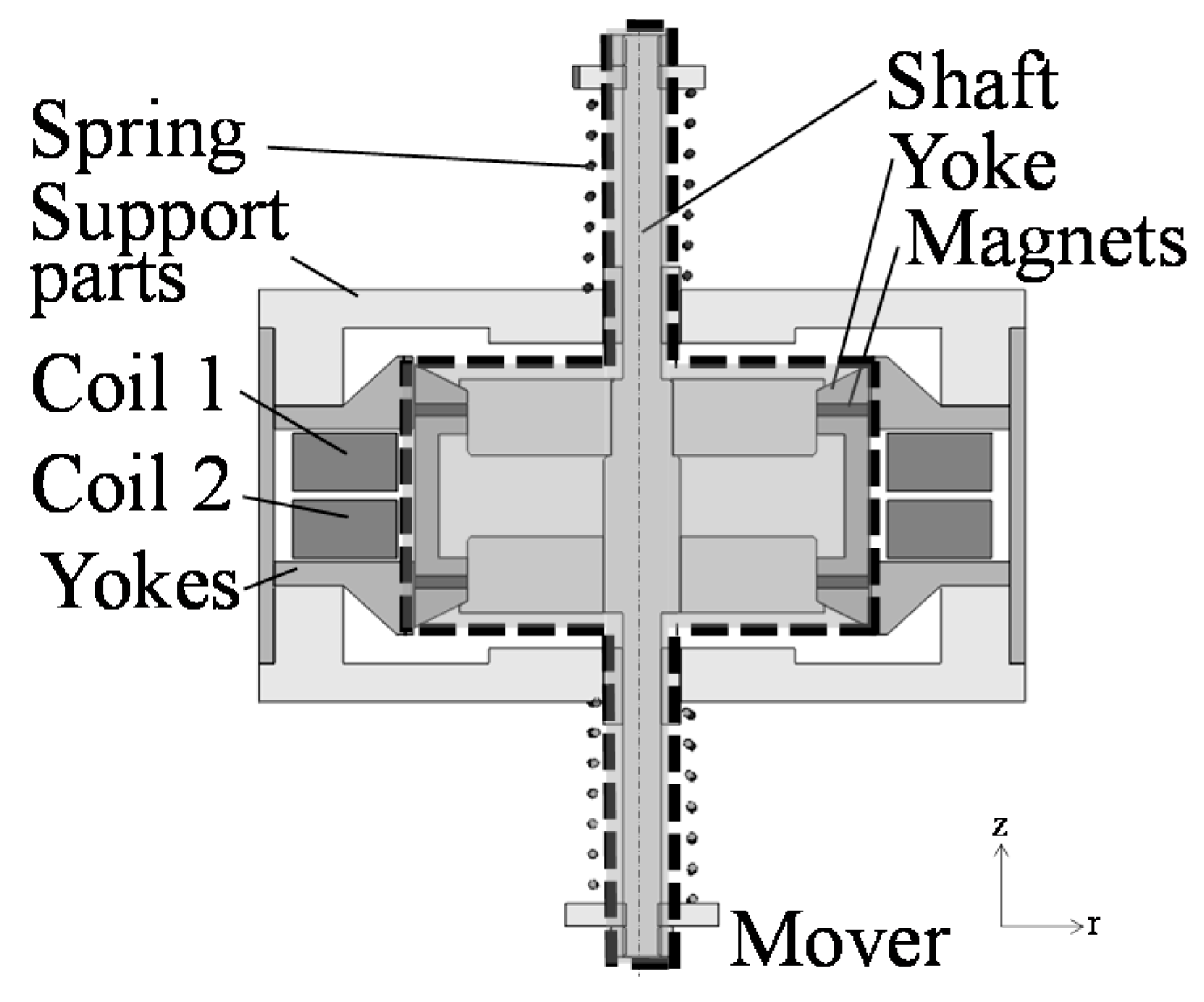
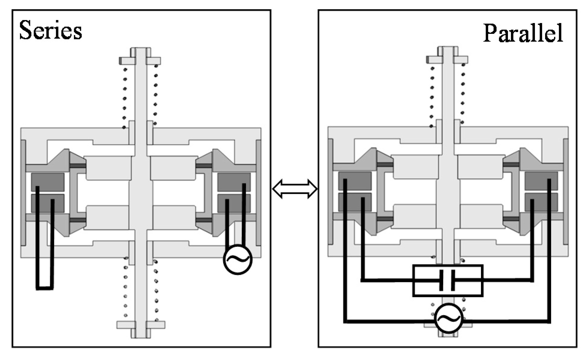
The cross-section view and coil connection of the proposed actuator are shown in
Figure 3 and
Figure 4. In the proposed actuator, variable characteristics can be realized by changing the coil connection in series or parallel. Due to the mechanism, a high thrust and vibration can be generated at a wide frequency range. In addition, the manufacturability can be improved due to introduction of a piled coil.
The actuator mainly consists of a mover and a stator. The mover is composed of a yoke, two ring-shaped permanent magnets magnetized in the moving direction, and a shaft made of non-ferromagnetic material. The stator is composed of yokes, two springs, two sets of coils, and supporting parts made of non-ferromagnetic material. The actuator can be easily manufactured because the stator is located outside the mover. As shown in
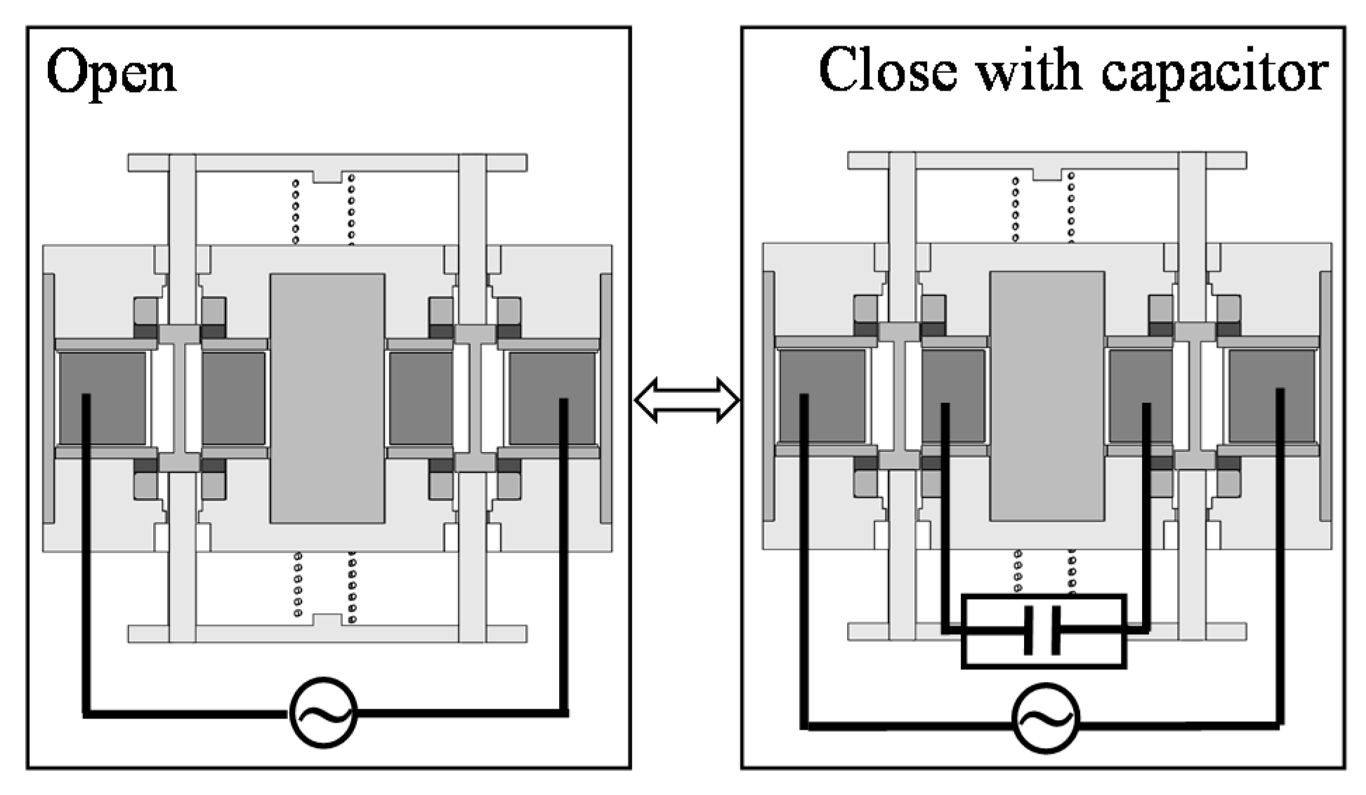
Figure 4, the coil connection can be changed in series or parallel. In the series connection, Coil 1 and Coil 2 are connected with a power supply. In the parallel connection, Coil 1 is connected with a power supply while Coil 2 is connected with a capacitor. Furthermore, electric switching devices are necessary to change the coil connection. Additionally, the number of switching devices increases more than that in the previous actuator because the coil connection is slightly complicated.
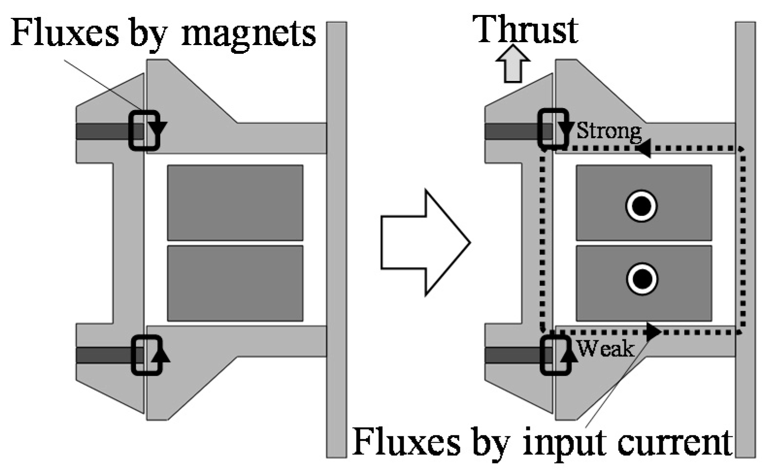
The operational principles at each connection are shown in
Figure 5 and
Figure 6. When the coils are not excited, the magnetic flux distribution around the upper ring magnet is the same as the lower ring magnet, and no thrusts are generated. In the series connection, currents in Coil 1 and Coil 2 produce unbalanced magnetic fluxes, which generate a thrust in the upper direction. In this way, an AC current in the coils generates an AC thrust, and the mover is oscillated [
7,
12]. In the parallel connection, when the mover is oscillated due to an AC current in Coil 1, an induced voltage is generated, and an induced current flows in Coil 2. In this time, the amplitude and the phase angle between Coil 1 and Coil 2 are different from each other because they depend on the drive frequency. Therefore, Coil 2 can generate thrust, and the mover is oscillated by the thrusts.
In the proposed actuator, a thrust constant is expressed by Equation (1).
where
F is the thrust,
I1 and
I2 are the currents in Coil 1 and Coil 2, respectively,
Iinput is the input current, and
A1 and
A2 are thrust constants of Coil 1 and Coil 2, respectively. In the series connection, the current in Coil 1 and Coil 2 are equal to the input current, and a thrust constant is derived as Equation (2). In the parallel connection, the current in Coil 1 and Coil 2 are equal to the input current and induced current, respectively, and a thrust constant is derived as Equation (3).
where
Iinduced is the induced current. From these equations, a thrust constant is constant in the series connection and is not constant in the parallel connection.
When the actuator is driven at a constant frequency, a thrust constant in the series connection is higher than that in the parallel connection because the phase of the induced current is almost opposite to the input current, and thrusts generated by each current are cancelled in the parallel connection. When the actuator is driven at other frequencies, a thrust constant in the series connection is lower than that in the parallel connection because the phase of the induced current is almost the same as the input current, and thrusts generated by each currents are superimposed in the parallel connection.
The oscillation of the mover is influenced by the mechanical resonance in the series connection. On the other hand, the oscillation is influenced by the mechanical resonance and induced current in the parallel connection.
From these operations, the frequency characteristics of the thrust and vibration are different and depend on the conditions of the coils. In other words, high thrusts and large vibration can always be generated under lower current by changing the coil connections according to the drive frequency.
3. Analysis Method
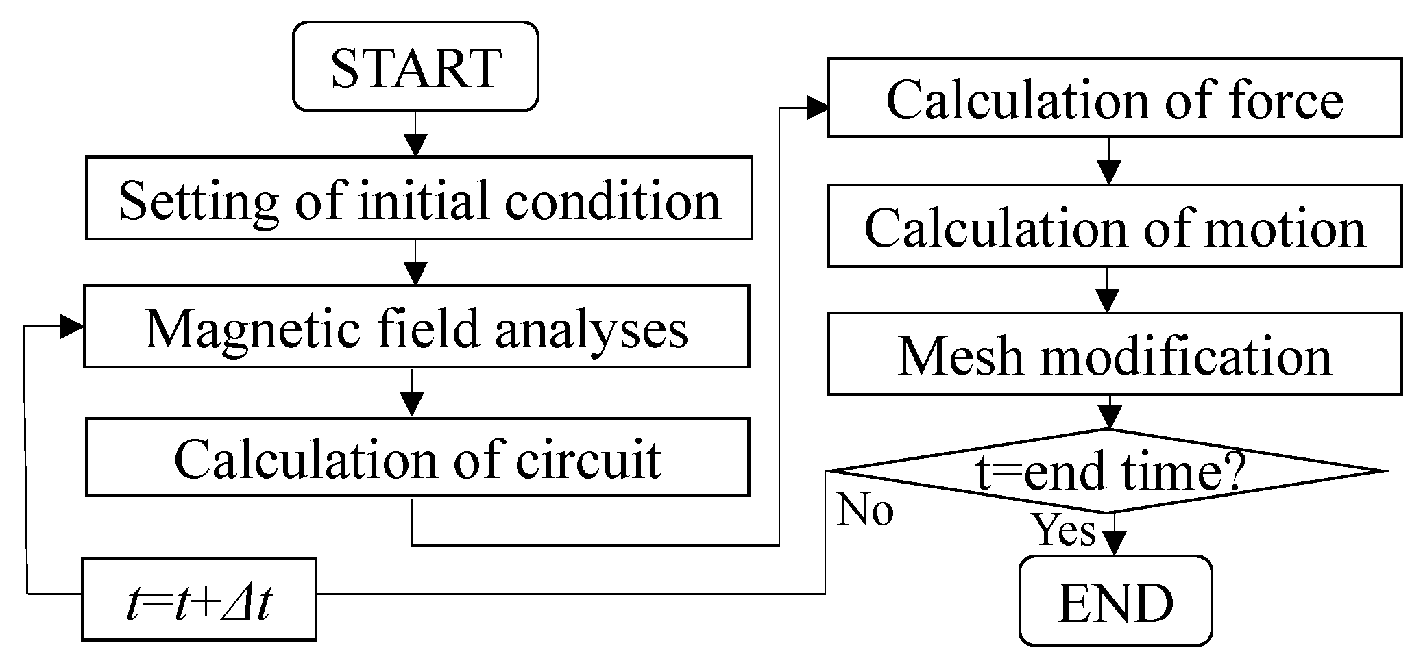
In order to verify the operational principle of the proposed actuator, a magnetic field analysis with a motion and circuit equations was conducted as shown in
Figure 7 [
13,
14]. In the magnetic field analysis, the magnetic fluxes are calculated from Maxwell's equation using the 2-D finite element method. Additionally, the electromagnetic force is calculated by the Maxwell's stress method. In the circuit analysis, a current in the series connection is calculated from a circuit equation shown in Equation (4).
Similarly, the currents in the parallel connection are calculated from the following two circuit equations:
Finally, the mover position is calculated from a motion equation shown in Equation (7).
where
V is the applied voltage from the power supply,
N1 and
N2 are the number of turns in Coil 1 and 2, respectively,
R1 and
R2 are the resistance of Coil 1 and Coil 2, respectively,
Ψ1 and
Ψ2 are the interlinkage flux per turn of Coil 1 and Coil 2, respectively,
C is the capacitance of the capacitor,
M is the mass of the mover,
D is the damping coefficient,
K is the spring constant, and
Fs is the friction force. In the analyses, iron losses are not considered.
4. Analyzed Results
A sinusoidal voltage that has an amplitude of 1.2 V and a frequency from 20 to 200 Hz was applied. The analysis conditions are shown in
Table 1.
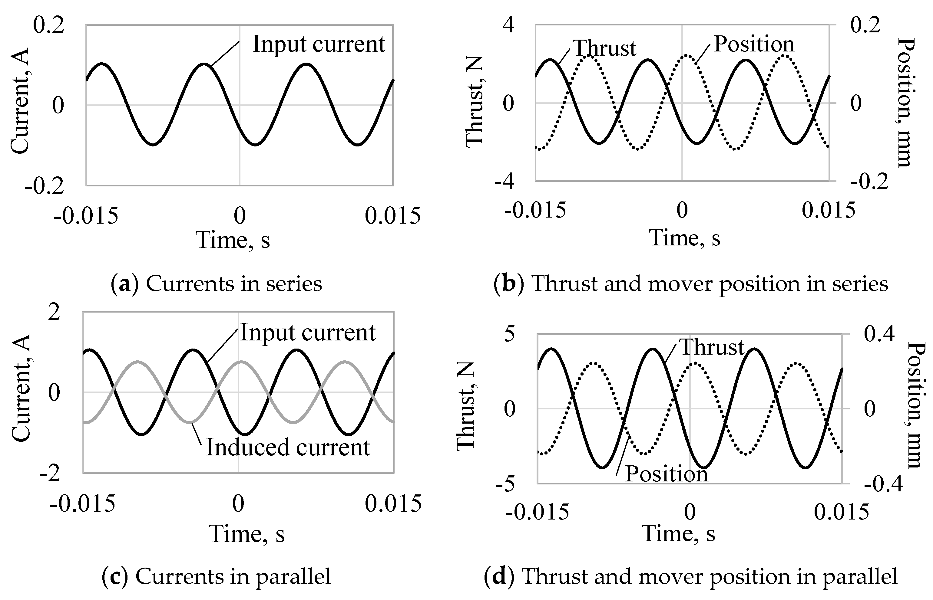
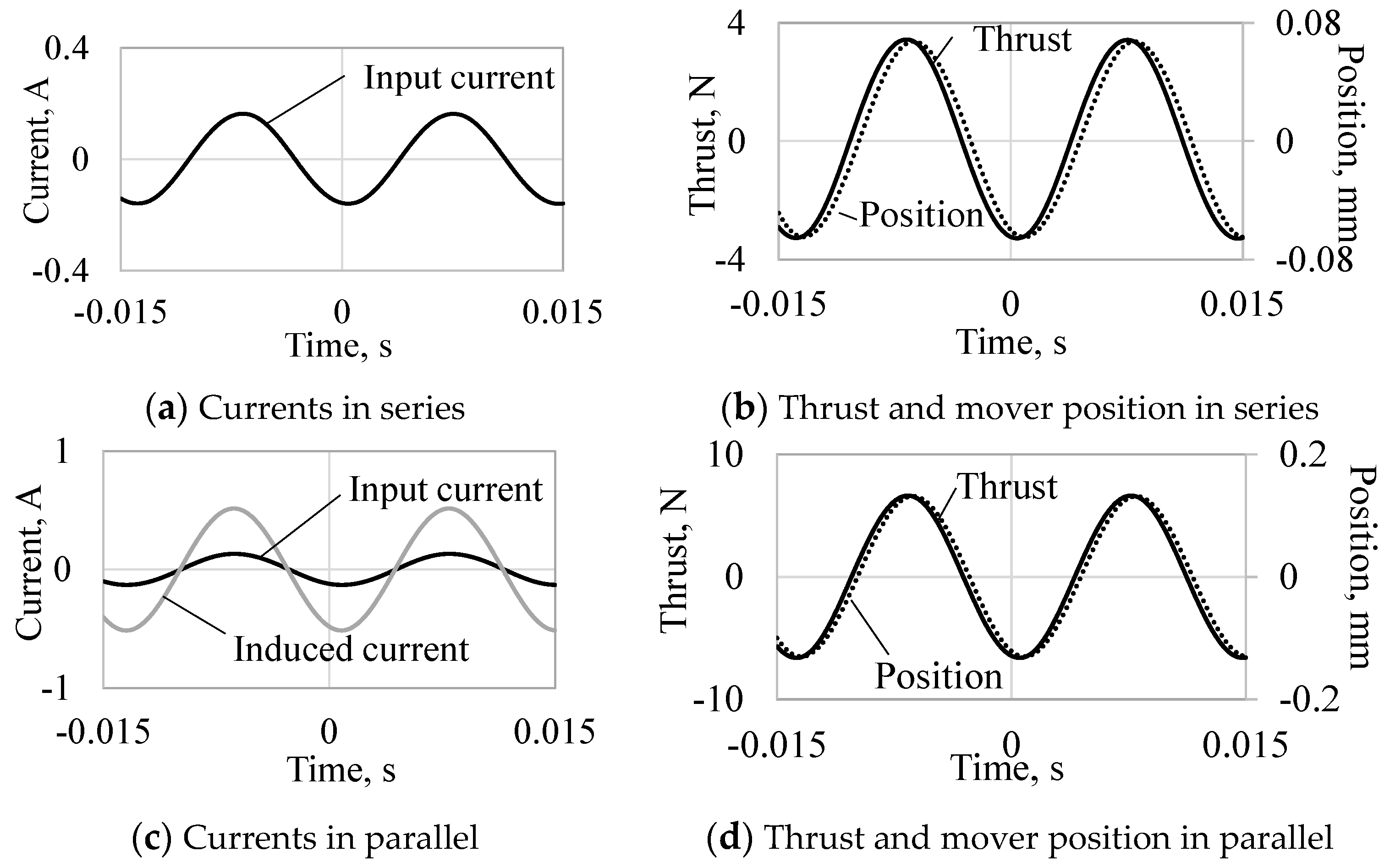
Figure 8 and
Figure 9 show the currents, thrusts, and mover positions at 70 and 100 Hz, respectively. When the actuator is driven at 70 Hz, the thrust constants in the series and parallel connections are 21 N
amp/A
amp, and 41 N
amp/A
amp, respectively. Furthermore, when the actuator is driven at 100 Hz, the thrust constants in the series and parallel connections are 21 N
amp/A
amp and 3 N
amp/A
amp, respectively. The thrust constant in the parallel connection is higher than that in the series connection at 70 Hz because the phase difference of the currents is almost zero and is lower at 100 Hz because the phase difference is opposite, as shown in
Figure 8c and
Figure 9c. The vibration amplitudes per input current amplitude (vibration constants) in the series and parallel connections are 0.41 mm
amp/A
amp and 0.91 mm
amp/A
amp, respectively, at 70 Hz. The vibration constants in the series and parallel connections are 1.18 mm
amp/A
amp and 0.23 mm
amp/A
amp, respectively, at 100 Hz. The vibration constant in the series connection is larger at 100 Hz because of the mechanical resonance frequency (96 Hz) depending on the mover weight and the spring stiffness, and that in the parallel connection is larger at 70 Hz due to the higher thrust constant.
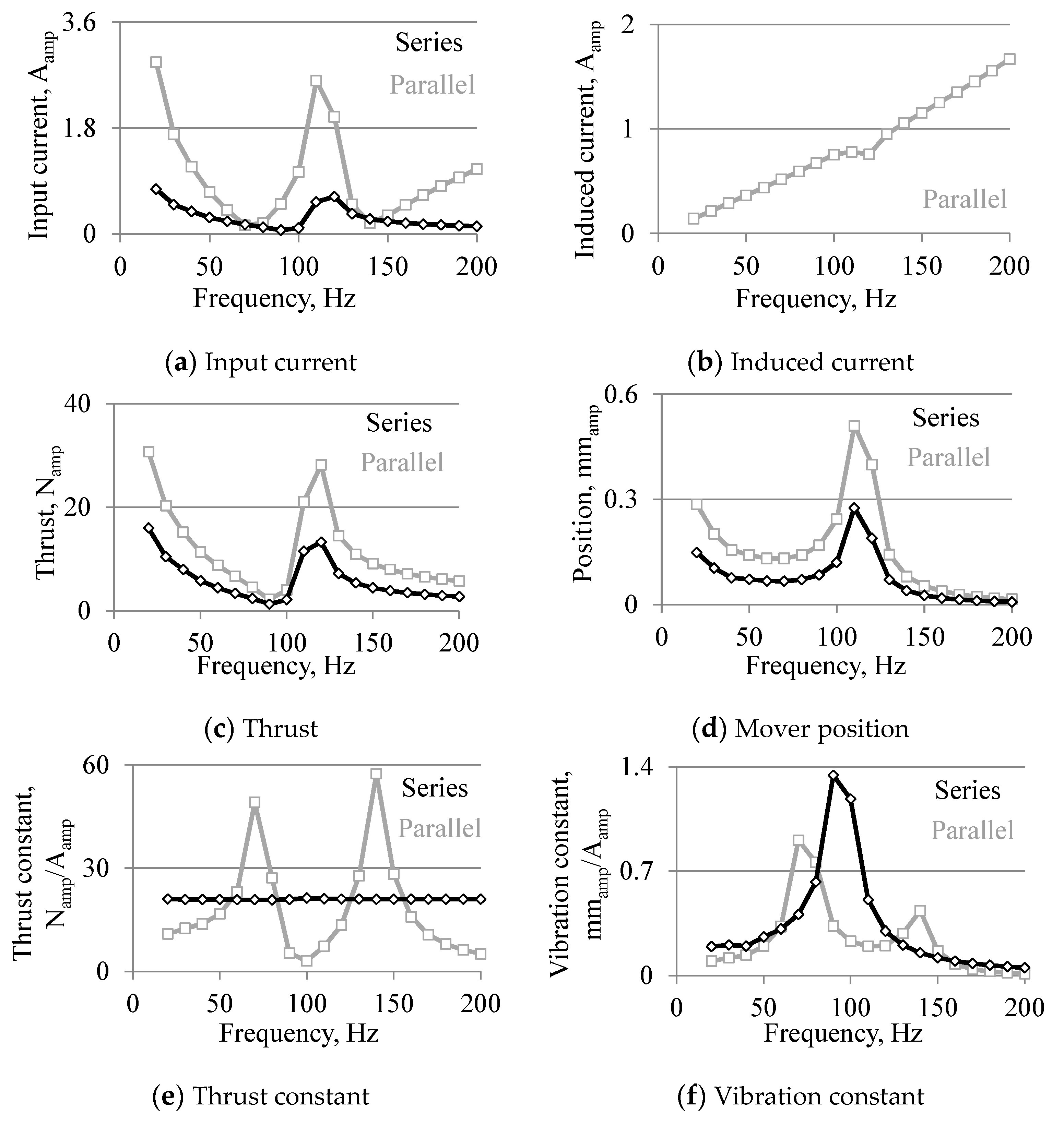
Figure 10 shows the analyzed results when the drive frequency is changed. From
Figure 10a–d, the input current, thrust, and mover position are influenced by the mechanical resonance, inductances, and capacitor. In addition, the input current, thrust, and mover position in the parallel connection are higher than those in the series connection at almost all drive frequencies because the resistance of the coil that is connected to the power supply is small. Additionally, the input current is extremely small at 70 and 140 Hz in the parallel connection. As shown in
Figure 10e, the thrust constant in the series connection is constant with respect to the drive frequency, and that in the parallel has two peaks at 70 and 140 Hz. As shown in
Figure 10f, the vibration constant in the series connection has a peak at 100 Hz because of the mechanical resonance, and that in the parallel connection has two peaks at 60 and 140 Hz due to the higher thrust constant.
Additionally, high thrust and large vibration can be generated by small currents from 60 to 80 Hz, and from 130 to 150 Hz in the parallel connection and at other frequencies in the series connection.


