FingerScanner: Embedding a Fingerprint Scanner in a Raspberry Pi

Department of Computer Science and INSPIRES, University of Lleida, Jaume II 69, Lleida 25001, Spain
*
Author to whom correspondence should be addressed.
†
These authors contributed equally to this work.
Sensors 2016, 16(2), 220; https://doi.org/10.3390/s16020220
Submission received: 14 October 2015
/
Accepted: 30 January 2016
/
Published: 6 February 2016
(This article belongs to the Section Physical Sensors)
Abstract
:Nowadays, researchers are paying increasing attention to embedding systems. Cost reduction has lead to an increase in the number of platforms supporting the operating system Linux, jointly with the Raspberry Pi motherboard. Thus, embedding devices on Raspberry-Linux systems is a goal in order to make competitive commercial products. This paper presents a low-cost fingerprint recognition system embedded into a Raspberry Pi with Linux.
1. Introduction
This project consists of the development of a low-cost and competitive security environment of fingerprint recognition based on a GT (511C1R) device, and embedded into a Raspberry Pi B+ (from now on, it is denoted as Raspberry) with Raspbian Linux.
This work presents a preliminary study about the viability of integrating a fingerprint device and a Raspberry with Linux into the same framework and, at the same time, providing a user interface by means of a web server. This first prototype, called FingerScanner, is a security system that provides the users a means to be validated by using a fingerprint scanner. FingerScanner can then be used to build much more complicated systems on top of it. However, we are interested in focusing our attention on designing an efficient prototype with a competitive performance.
This manuscript can be the basis for other possible projects that encourage Raspberry and similar boards developers to create interesting projects about accessibility, security, etc, combined with low-cost fingerprint scanners. A sample project could be a safe deposit box with a FingerScanner. Nowadays some enterprises in the sector of cash handling that use finger-print sensors (i.e., Sallén, http://www.sallen.es) complain about the fingerprint tools (to develop an application) and sensor cost. So, our project can become the basis of the low-cost systems based on fingerprint sensors.
The remainder of this manuscript is organized as follows. Section 2 details the related work and motivation as well as the contributions of this paper. Section 3 introduces the main features of the devices used in this project. Section 4 presents the design of the proposed FingerScanner application. The experimentation described in Section 5 evaluates the performance and efficiency of our proposed solutions. Finally, Section 6 outlines the main conclusions and future work.
2. Related Work
Nowadays, there is a growth in Raspberry projects. There are many interesting projects similar to ours. Website [1] is full of Raspberry projects in many different areas. We only highlight one of them, Node-pi-alarm [2], where sampling data obtained from cameras and sensors are displayed on a website. The main similarity with our project is that the web server was made in Node.js inside the embedded system.
The authors in [3] present a security home system based on the Internet of things. However, security issues concerning the management of a huge number of connected devices cost effectively has emerged in this research field. This article presents a system to connect a door to Internet, so that the access control system can be controlled from anywhere in the world. It provides such facilities as visitor recording, notification and chat with the administrator and remote door lock/unlocking. Communication is based on Twitter and email. This system uses a Raspberry and manages various sensors via Internet. The idea presented can be extended from our FingerScanner prototype.
In [4], a real-time monitoring system for a fire alarm was proposed that detects and takes pictures in the presence of smoke, called Firefighter. The embedded systems used to develop this fire alarm system were Raspberry and Arduino Uno. The key feature of the system is the ability to display an image of the room state on a web page when a fire is detected through the presence of smoke. The system needs user confirmation to report the event to the Firefighter server through an SMS message. The advantage of using this system is that it reduces the possibility of false alerts reported to the server. The drawback is the human interaction required to take decisions and the high power consumption. In addition, the real-time need forces the use of a non-free SMS messaging system. As our project, it is based on a Raspberry and uses a web page as the visual information system. However, the use of SMS messages is a good solution to implementing real-time communication systems.
In [5], a design and implementation method for RESTful WSN Gateways was proposed using Node.js, as in our project. The gateway is designed as an embedded Linux device, which can handle multiple accesses with both sensors and servers. As in our project, it used the Raspberry and a web page as the visual information system. The real-time requires the use of an SMS messaging system.
In [6], a sensor secure node server to communicate over Bluetooth using RC4 encryption algorithm between a mobile phone and its monitoring equipment was proposed. An analogous idea should be incorporated into our system to provide more secure communications.
In [7], pressing an alarm switch enables a PIR sensor and a USB camera is turned on for 10 s and records the face of the person at the door. The captured video is then transmitted to the administrator through a 3G dongle with a unique IP address.
Other papers also deal with the design and implementation of smart surveillance monitoring system using Raspberry and some sort of sensors [8] and alert with SMSs messages [9].
In [10], the Raspberry operates and controls motion detectors and video cameras for remote sensing and surveillance. For instance, when motion is detected, the cameras automatically initiate recording and the Raspberry device alerts the homeowner of the possible intrusion through a web page. In general, globally accessible automation of electronic appliances in a user friendly way can be made possible with the use of a Raspberry micro-controller board, an Internet connection and relay switches [11].
The authors in [12] developed a methodology with low time computational complexity for detecting fingerprints, where a support vector machine (SVM) learning method was proposed. High computing performance required in detection, where instant system responses are required was shown in a project where real-time face detection on Raspberry’s graphic processor was presented in [13].
The authors in [14] explain how to create an intelligent, high-efficiency street lighting system based on a Raspberry. In this case, the authors linked the Raspberry to two ZigBee sensors to switch the streetlights on and off.
A new inexpensive vineyard protection against hailstorm was presented in [15]. Each row has an “umbrella” which protects the product without hindering the mechanical activities. It had an electronic card and a ZigBee mesh telecommunication network to transmit data to a Raspberry Pi that manages the protection.
As another example of low-cost solutions, the authors in [16] presented a multi-parameter acquisition system for volcanic monitoring also based on the Raspberry. The acquisition system was developed using a System on a Chip (SoC) Broadcom BCM2835 Linux operating system (based on DebianTM) that allows for the construction of a complete monitoring system offering multiple possibilities for storage, data-processing, configuration, and real-time monitoring of volcanic activity.
Almost all the cited projects (like our own) rely on the communication performance provided by the Raspberry. In [17], Raspberry was shown as a cheap, flexible, fully customizable and programmable small computer embedded Linux board. In [18], measurements showed that processing rates of up to 230 Mbps and the energy consumption per bit with the Raspberry can be as small as 3 nJ/bit. Then, Raspberry was shown to be an inexpensive, viable and flexible platform to deploy networking projects on.
Although all of them were well-structured proposals, none of them analyzed the efficiency of the system in depth. We measured the CPU and Memory of the embedding system used (i.e., Raspberry) and different alternatives to implement the application presented (FingerScanner) were analyzed. In addition, an in-depth analysis of the browser (where controlling messages are displayed) was performed. In addition, special attention was paid to finding the most efficient devices, in other words, those with the best quality/price relation. This is an important requirement in manufacturing industry because the final products must be as competitive as possible.
3. Preliminary Concepts
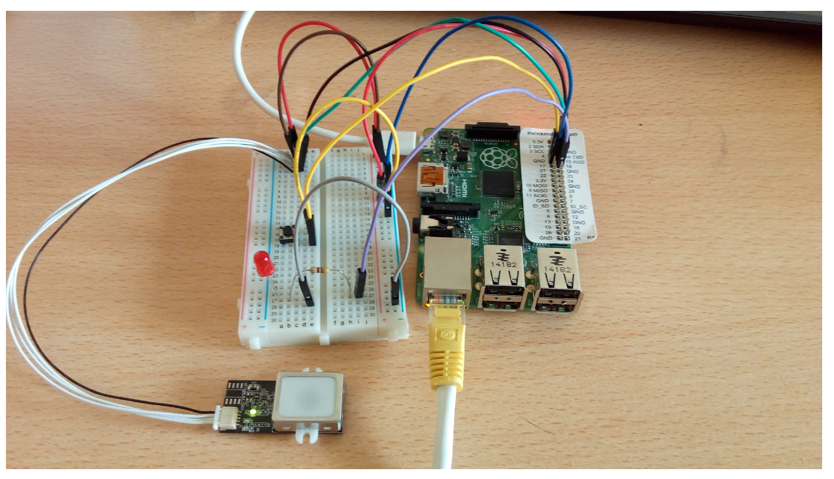
The main components of our framework are (see Figure 1):
- Raspberry Pi B+. Due to its characteristics, this was the motherboard selected from among others (BeagleBone Black, HummingBoard, MinnowBoard Max, Pengwyn, Hachiko Board, etc.).
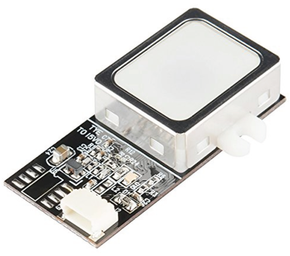
- The Fingerprint Scanner GT(511C1R) (Figure 2). This device uses 4-pin connector to communicate with the Raspberry.
- JST SH Jumper 4 Wire Assembly. This is the fingerprint Scanner connector. It has 4 pins to connect Voltage (3, 3–6 V), ground, TX and RX of different devices (in our case, the scanner and the Raspberry).
- The Douself Sola magnetic lock. When receiving a voltage of 12 V, it joins the two formed pieces. When voltage goes down, the two pieces separate.
- Simple red LED. It emulates the magnetic lock. The magnetic system is activated (deactivated) when the light is on (off).
- Simple switch component. It activates the scanner when pressed.
- The main programming language was Node.js.
The main features are explained below.
Figure 1.
This image shows the physical connections between the Raspberry and the peripheral devices. The LED emulates the magnetic lock. An Ethernet connection is also needed because the Raspberry runs a Node.js web server.
Figure 1.
This image shows the physical connections between the Raspberry and the peripheral devices. The LED emulates the magnetic lock. An Ethernet connection is also needed because the Raspberry runs a Node.js web server.

Figure 2.
Fingerprint Scanner GT(511C1R).

3.1. Raspberry
Nowadays, Raspberry is one of the most popular embedding systems with Linux support. The Raspberry community has grown continuously since its creation. It is a low-cost embedded system so some of the supported operating system are based on Debian, an open-source Linux distribution. It provides a very fluent developing software that you can downloaded from the Raspberry website (https://www.raspberrypi.org).
Raspberry Pi B+ (the model selected in this project) supports the following operating systems: Raspbian, Snappy Ubuntu Core, Openelec, Raspbmc, Pidora and Risc. We chose Raspbian because it is one of the most stable and well-documented operating systems. Raspbian is a Linux Distribution based on Debian Wheezy. We used a pre-compiled version for the Raspberry, which includes the basic developing tools, such as the Advanced Package Tool (APT).
3.2. Fingerprint Scanner Device GT(511C1R)
We chose the Fingerprint Scanner Device GT (511C1R) because it is very cheap and provides a well-documented manual, a Linux-compatible module as well as a good price/quality relation. More precisely, it provides a high-speed, high-accuracy fingerprint identification using the SmackFinger 3.0 Algorithm. It provides a 32-bit CPU at 72MHz (ARM Cortex M3) and a database which can store up to 20 different fingerprints. It is able to recognize a fingerprint in whatever 360 position. Downloads and uploads of fingerprint scans can be done by using the RS-232 serial interface. It provides a UART (Universal Asynchronous Receiver/Transmitter) connector (Default 9600 baud). Communication based on an UART communication protocol can operate through a serial RS-232 cable, the one chosen for this project. Power is supplied through a JST-SH connector.
The Fingerprint communicating protocol is based on packet handshaking. There are three kinds of packet:
- Command packets: Used to order the device to carry out operations (i.e., check for finger-button pressing).
- Response packets: They indicate operation success/failure. The opcode of the command field can be ACK(0x30) and NACK(0x31), indicating operation success and failure respectively. In case of failure, the ERROR code is also provided.
- Data packets: The data field does not have a static length because this packet is used to send extra information, fingerprint images, etc.
As a summary of functions, the Fingerprint scanner is small, cheap and gives accurate and rapid identification of fingerprints with an on-board optical sensor, stores 20 fingerprints in its database, and allows a single entry or the entire database to be downloaded and uploaded, among other features.
3.3. Software
We used Node.js as the main programming language. Node.js uses an event-driven, non-blocking I/O paradigm which makes it lightweight and efficient. It is perfect for data-intensive real-time applications and underpowered devices.
There are many modules Module: program component, linked dynamically to a program with the linker. Programs are composed of one or more independently developed modules that are not combined until the program is linked. A single module may contain one or several functions. Available for Node.js, such as the Buffer module, which allows communicating with the devices in the assembler. Among other reasons, Node.js was selected because it provides facilities to develop a driver for the FingerScanner. A module is made up in turn by a set of specialized functions. The modules can be written in JavaScript, and can be installed with the help of the npm utility.
To implement the asynchronous communication between the server (Node.js) and the scanner device, the Buffer module was used. Another possibility was to use addons. An addon is a dynamic shared object link written in C/C++, which integrates the V8 engine (a Google open-source library). With the help of V8 engine, C++ objects can be transformed into JavaScript code, which in turn are compatible with the Node.js application.
We discarded the addons option due to its difficulty and slowness. In this project we used the Buffer jointly with the Promise module, both integrated into a more generic module, gt5113, which also includes the Serialport module.
Finally, controlling the FingerPrint scanner with Node.js enables its features to be extended easily. For these reasons, we developed the FingerScanner application with Node.js.
4. FingerScanner
FingerScanner is a security system that provides a means to validate registered users by using a fingerprint scanner.
The FingerScanner application follows a server-client paradigm. The client (which can be executed in a computer, tablets, smartphone and even in a Raspberry browser) makes requests to the server and this replies to the client. An administrator controls the system by using a web application that acts as the client. The server (running in the Raspberry) and implemented with Node.js), is responsible for managing the overall system, the Raspberry and their components and the devices attached to the Raspberry. Figure 3 shows the FingerScanner architecture. The FingerScanner components, client, server and devices (magnetic lock, fingerprint scanner GT511C1R and switch) can be seen, as well as their communicating links.
Figure 3.
FingerScanner architecture.

The administrator can register, delete and update users. The administrator, by means of a web page, sends user data to the server, which stores and interacts with a fingerprint scanner to perform the action requested from the client.
If a registered user wants to be validated, they must press a switch to activate the fingerprint scanner. If validated, the FingerScanner server unlocks the magnetic lock. Otherwise, the magnetic lock remains locked (action by default). If, for example, the magnetic lock is connected to the security system of a safe, this can control access to it.
In order to reduce the server work, the Angular.js framework was used to implement the client. Angular.js allows DOM (Document Object Model) objects to be manipulated, avoiding requests to the server. With the help of Angular.js, the client was implemented as a dynamic web. The main difference between a dynamic and non-dynamic web is the way the required client services are sent back from the server. When a user clicks on a link in a non-dynamic web, the server replies with an HTML page and its associated JavaScript code. Instead, in a Dynamic web, the server replies contain only data and the client is responsible for rendering the page. This greatly reduces the server work.
The server (implemented with Node.js) is responsible for receiving and dealing with signals from different devices (clients, switch and fingerprint scanner) connected to the Raspberry. To respond to inputs from devices or clients, Node.js implements event listeners Event Listener. Program (or function program) activated asynchronously by an event, that execute on the asynchronous arrival of their associated events.
The server stores registered users in a little relational SQLite database. SQLite is a small database used on systems with limited memory. The size of the database occupies up to 6 KB (when it stores 20 fingerprints). It uses a packet-exchanging serial communication with the Fingerprint scanner. It also controls the GPIO (General Purpose Input/Output) pins, through which the signals to/from the switch and the magnetic lock are sent/received.
The server activates (closes) the Magnetic lock when pin 12 voltage is 5 V (Logical 1). With 0 V (Logical 0), it is deactivated (opened). When the Identify process in the scanner ends successfully, the server sends the event “Logical 0” to the “Magnetic lock” pin to open it for a period (3 s). The module rpi-gpio is used to control the Raspberry pins. This module catches the voltage changes in the input pin (switch pin) and sets “Logical 0” or “Logical 1” into the output (magnetic lock) ones. Thus, the switch and Magnetic lock devices are controlled by the rpi-gpio module that catches and sends voltage changes to the pins (7 for switch pin and 12 for Magnetic lock pin)
The FingerPrint scanner is controlled differently. It is connected to the serial port TTYAMA0 (pins TXD and RXD). The device receives input packets from the server (located in the Raspberry) and then returns response packets to the server using the serial port. This device has a small database that can store up to 20 fingerprints. Every scanned fingerprint has an associated ID (Identifier), which holds additional information about the fingerprint, saved in the server database (the SQLite one).
To deal with communication with devices and the client, it was necessary to install the following modules: Express, gt511c3, Promise, SQLite, SerialPort and rpi-gpio.
4.1. Communication Client-Server
In this section the communication protocol between the client and the server is presented. The client sends requests to the server by means of sentences formed by a HTTP method and an URI. An HTTP method indicates what the server has to do with one of the URIs (Uniform Resource Identifier) listed in Table 1.

| Method | URI | Description |
|---|---|---|
| GET | domain/fingerprints | Obtain all information of all fingerprints |
| domain/fingerprints/id | Obtain all information of one fingerprint | |
| domain/fingerprints/identify | Obtain information of the finger on the sensor | |
| POST | domain/fingerprints | Save new fingerprint |
| PUT | domain/fingerprints/id | Update one fingerprint |
| DELETE | domain/fingerprints | Erase all information of all fingerprints |
| domain/fingerprints/id | Erase all information of one fingerprint |
There are different Angular.js controllers in the client. The Angular.js controllers are objects that allow the client logic to be developed as well as giving full control of the data. These controllers (made in JavaScript) perform specific functions inside the web page. Every controller has associated a JavaScript function activated asynchronously when users perform an action in the web. Some controller utilities implemented in our project are requests to the server for resources, show/hide elements in the DOM (Document Object Model), verify user data, etc. In other words, the interface sends requests to the server and the responses are managed by Angular.js controllers. As an example, usersController administrates the incoming server petitions requesting the registered users, or modifying or deleting a registered user. Depending on the server response (i.e., success or failure), the controller alerts the user with a message on the web browser that everything went well or the occurred error. The other controllers implemented are enrollController, which controls the Enroll process (explained in Section 4.2.1) and loginController that only allows admin access.
The Express module obtains the client request. Express provides facilities to parse the information (body request, parameters, query in the URL, ID, etc.) of the client request. When the server receives a new request, Express launches a thread with a URI as argument. The server will execute the action associated to such a URI. Table 1 shows the action server associated with each URI. For example, with the GET method and URI domain/fingerprints, the client is asking for registered fingerprints. The server will send back all the fingerprints entries to the client. In this example, the client is only requesting data, but sometimes the client must send extra information. Additional information may be requested by the server in the POST and PUT methods.
According to the elements involved, the client requests (and more specifically their URIs) can be classified into three groups:
- URIs where the server communicates with the local SQLite database (GET domain/fingerprints/, GET domain/fingerprints/id).
- URIs where the server communicates with the FingerPrint scanner (DELETE domain/fingerprints/, DELETE domain/fingerprints/id).
- URIs requiring human interaction.
It should be mentioned that two routes were not implemented because they are meaningless. These were POST domain/fingerprints/id and PUT domain/fingerprints (see Table 1).
4.2. Communication Server-Devices
In this section, the communication between the Raspberry and the different devices (switch, magnetic lock and fingerprint scanner GT511C1R) is presented.
The switch and magnetic lock are connected to the GPIO pins. The server knows which pins are connected by using the rpi-gpio module. This module can set the direction of the two GPIO pins (the input and output ones) and capture the signals produced in these pins. Thus, using the rpi-gpio module, the switch is assigned to the input pin and the magnetic lock to the output one.
An event listener is assigned to the switch pin. When caused by human interaction with the switch, the voltage in the GPIO pin changes. Then, the event listener is called. This voltage change means that a human user wants to be identified. The server captures the event in the GPIO pin. This informs the scanner that a new identification process must begin.
The output pin, assigned to the magnetic lock changes its voltage to activate or deactivate the magnetic lock. This change informs the user that the identification process has been successful.
The fingerprint scanner operation is more difficult than the other two devices. It is governed by a communicating protocol (based on the packet-exchanging handshake) between the server and the Fingerprint scanner device.
The command set used in the communication protocol (commands, errors, arguments, etc.) of the Fingerprint scanner is explained in depth in (https://goo.gl/RwWdg4). The messages are made up of one or two packages (depending on whether data is/is not needed):
- Command Packet (10 Bytes): Packet sent from the computer to the scanner. It contains: scanner Id, instruction, arguments and checksum.
- Response Packet (10 Bytes): Packet sent from the scanner to the computer. It contains: response, scanner ID, checksum, and ACK or NACK indicating operation success or failure respectively (when NACK, it also contains the error code).
- Data Packet: Additional package of data to command or response packets. Its size depends on the data transmitted and it is used in the following operations: Open(opcional), MakeTemplate, GetImage, GetRawImage, GetTemplate, SetTemplate.
Fortunately, a module named gt511c3 was recently released. The gt511c3 uses two other important modules, Promise and Serialport. The gt511c3 module implements the overall commands (the command packet and each corresponding response packet), which are in turn grouped into functions. All these functions return a Promise (an object provided by the Promise module), which contains the error code.
The Promise module is also used to implement the sequential code. There can be many threads executed in parallel running Node.js functions, as long as they are activated asynchronously. The Promise module can organize parts of the application to be executed sequentially in order to have more control over the asynchronous execution.
The Serialport module provides functionality to configure serial communication (baudrate, databits, stopbits, etc), and initiate and finish the serial communication. In our case, only the baudrate (115,200 or 9600 baud) was changed.
The main process steps of the server-scanner communication are:
- Enroll (Record) a new fingerprint.
- Delete one or more fingerprints from the DB scanner.
- Identify that an imprint is already properly stored in the BD scanner.
- Update a fingerprint is composed first by a Delete and then by a Enroll process.
The communication handshake between the scanner and the Raspberry in each of these three operations is explained next.
4.2.1. Enroll
The Enroll process (see Figure 4) consist of obtaining a fingerprint scan 3 times with the LED on, and saving the image formed by merging these three scans in one of the 20 entries in the database device. Before calling the Enroll module function, it is necessary to obtain the occupied entries in the database by means of the getEnrollCount function. If the returned value is lower than 20, then the function ckeckEnrolled is called changing ID parameter, until the function does not return any error. The error means that the ID passed as a parameter is already stored in the scanner database. It returns the first empty entry (from 0…19) from the scanner database. Finally, the Enroll function with the ID entry number obtained as a parameter is called.
Figure 4.
Enroll Process.
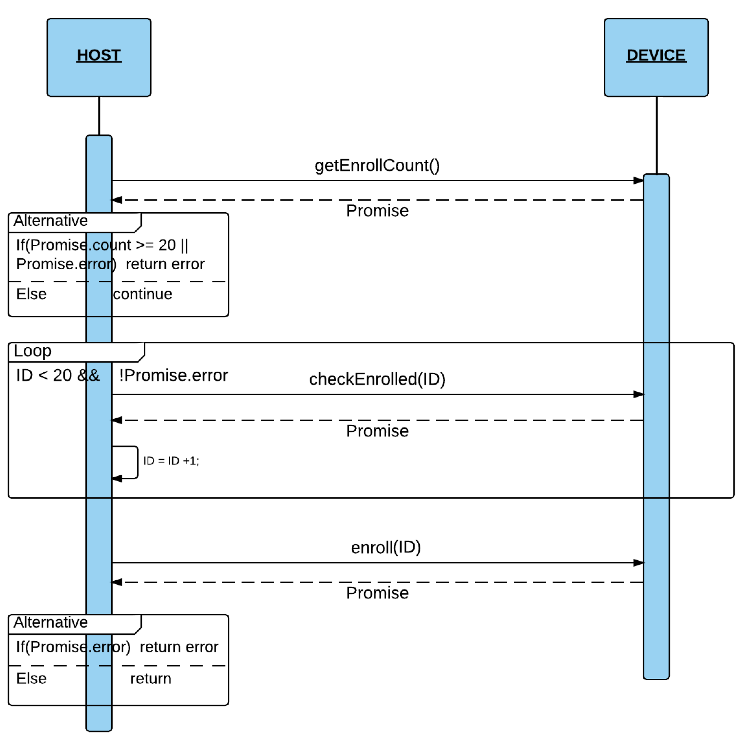
First of all, the Enroll function of gt511c3 switches on the LED and wait for a finger scan up to a predetermined timeout (10 s). After receiving the scan, the scanner device saves it in Memory. Then, it switches off the Led. Thus, when the LED is on, it means that the device is performing a scan. This process is repeated 3 times and then the scanner merges the 3 scans in only one image.
The Enroll function is implemented by the following functions in the gt511c3 module:
- ledONOFF: sends a signal to turn the LED on/off.
- EnrollStart: Allocates Memory space for Enroll1, Enroll2 and Enroll3, and checks if the ID (passed as argument) is already saved in the DB. If so, the Enroll process will finish returning the fingerprint ID.
- Enroll1, Enroll2: Obtains the scan of what is on the scanner and saves it in Memory. The LED must be on.
- Enroll3: Obtains the scan of what is on the scanner and saves it in Memory. The LED must be on. Then, it merges the three scans obtained with Enroll1, Enroll2 and enroll3.
4.2.2. Identify
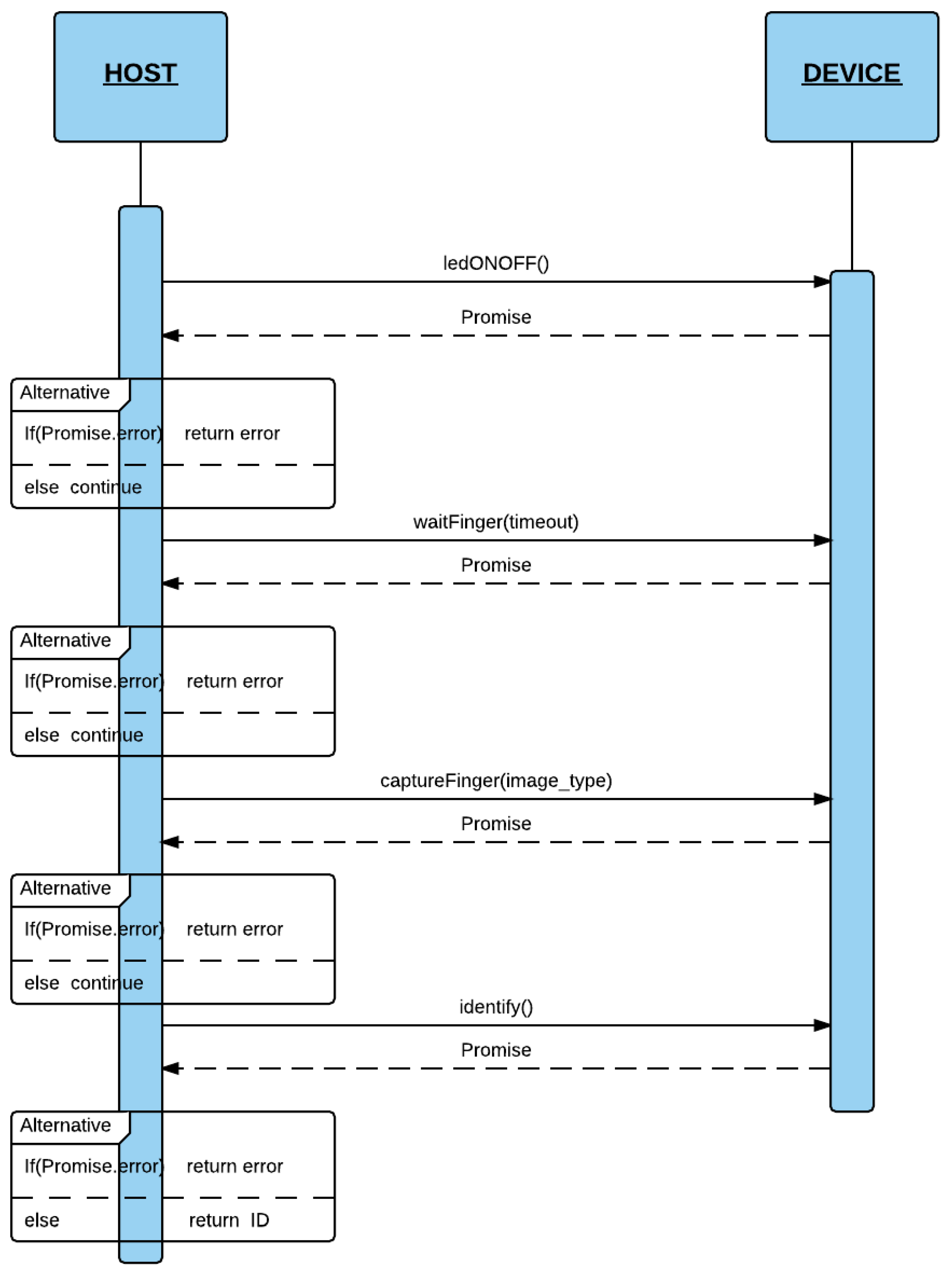
In this section, the identification process (dentify process) is presented. Figure 5 shows the process steps for identifying a fingerprint.
First, the scanner switches on the LED (by using the ledONOF function). Next, the server waits for a finger to be placed on the scanner (waitFinger function). When the finger is on the scanner, this informs the server accordingly. If successful (waiFinger and ledONOFF), the server sends a command packet with the captureFinger command using the captureFinger function. On receiving this, if a NACK is received inside a Promise, the server obtains the error code and decodes the error. In other cases (all were gone successful), the server runs the Identify function that sends the Identify command. Finally, the scanner returns the ID associated with the finger. If the finger is not in the database, it returns an error meaning Identification failure. Then, the server makes a query to its local SQLite database to obtain more information if the user is already registered. When the process has been completed successfully, the server switches off the LED.
Figure 5.
Identify Process.

4.2.3. Delete
Basically, the Delete process consist of sending a Delete command packet (deleteID or deleteAll packets) from the server to be removed from the Fingerprint scanner database. Upon receiving an encapsulated ACK from the scanner in a response packet, the Raspberry knows that the fingerprint has been removed successfully. The deleteID (passing the ID as argument) and deleteAll functions of the gt511c3 module delete one or all the ID fingerprint, respectively. These functions can produce the following errors in the Promise object: NACK_INVALID_POS and NACK_EMPTY_DATABASE. When the process finishes successfully, the SQLite database of the server changes the same ID fingerprint entries accordingly.
5. Results
We performed various experiments to test the computational performance of FingerScanner to validate its viability. First, the performance of the communication system was measured to obtain the response times. Then, the behavior of the different components of the system (client, server and scanner) was analyzed in depth.
5.1. Communication Client-Server-Device
Table 2 shows the response time of the server performing the URIs.
| Route | Time (in Seconds) |
|---|---|
| GET domain/fingerprint | 0.113 |
| GET domain/fingerprint | 0.104 |
| GET domain/fingerprint/identify | 4.5 |
| DELETE domain/fingerprint | 2.413 |
| DELETE domain/fingerprint/id | 2.587 |
| POST domain/fingerprint | 7.1 |
| PUT domain/fingerprint/identify | 8.457 |
We separated the results into three categories. URIs which only access the SQLite DB, URIs which also communicate with the scanner device and finally, URIs with human interactivity:
- SQLite (GET domain/fingerprints, GET domain/fingerprints/id): the response time of the SQLite database is very fast. Response time of the overall embedded system is very good.
- SQLite + scanner device communication (DELETE /fingerprints, DELETE /fingerprints/id): communication time is high. The time between opening the serial port and sending and message handshaking (receiving packet commands) is about 2 s. The serial port ttyAMA0 of the Raspberry can work at 9600 and 115,200 baud speeds. It was set at 115,200 baud. Overall, we have a robust but somewhat slower communication due to the limitations of the serial communication interface.
- SQlite + Device communication + Human interactivity (POST /fingerprints, PUT /fingerprints/id, GET /fingerprints/identify): in this category, the times are the longest due to human interaction.We compared the Enroll process time of the GT511C1R Fingerprint scanner (7.1 s) with the one obtained in a Oukitel u8 smartphone (10–15 s) with Android and an iPhone 6 (15–20 s). Thus, the GT511C1R Enroll time was the fastest. In the GT511C1R device, the Identify process was 4.5 s and the Ouktiel and iPhone took 2 and 1 s respectively. In this case, the GT511C1R Identify performance was the worst. We can conclude that the GT511C1R times are so good in terms of system usability. Actually, they are very competitive with current smartphone devices.
Significant differences between different categories can be observed. Although the overall assessment was satisfactory, there is room for improvement. In general, we can say that the system client-server-device communication worked properly.
5.2. GT511C1R Fingerprint Analysis
Table 3 shows the successful tries of the principal scanner processes, Identify and Enroll. In both operations, the number of successes in the first try is quite high compared with the remaining attempts. The efficiency of the scanner is in the 70%–80% range. However, the scanner behaved properly as long as the fingerprint occupied almost 100% the scanner area and it was pressed hard enough. The results reached the same conclusion after repeating 10 Identifications and 10 Enrolls.
| Routine | 1st Time | 2nd Time | 3rd Time |
|---|---|---|---|
| Identify | 14 | 4 | 2 |
| Enroll | 15 | 5 | 0 |
Another test was to identify the finger occupying less than 50% of the scanner area 10 times. The scanner did not pass the test, failing to identify it on any of the 10 tries. When there was a failure, the scanner always sent back an error packet.
Finally, we compared the effectiveness of the scanner GT511C1R with other scanners from a Oukitel u8 and iPhone (touchID) smartphone devices. Table 4 shows the times that both devices processed the Identify and Enroll operations correctly in 10 attempts. The results were similar as long as the scanner was in the same position. Unlike the smartphone scanner, the GT511C1R only operated properly in a horizontal position on a physical support. It needed to be fixed to a physical platform.
| No Movement | Movement | |||||
|---|---|---|---|---|---|---|
| gt511c1r | u8 | iPhone | gt511c1r | u8 | iPhone | |
| Identify | 7/10 | 8/10 | 10/10 | 2/10 | 7/10 | 9/10 |
| Enroll | 8/10 | 10/10 | 10/10 | 1/10 | 8/10 | 10/10 |
5.3. Analysis of the Node.js webServer
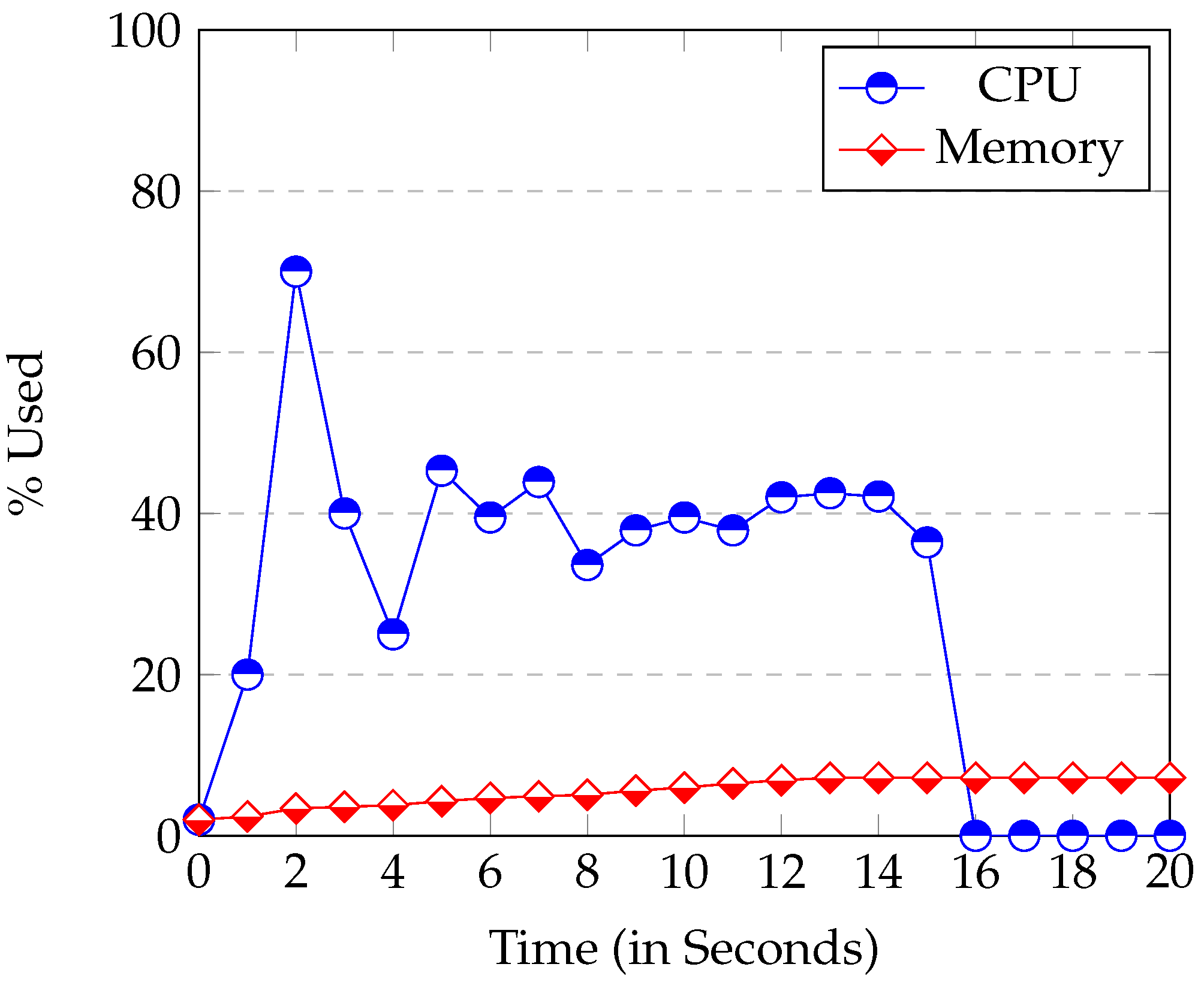
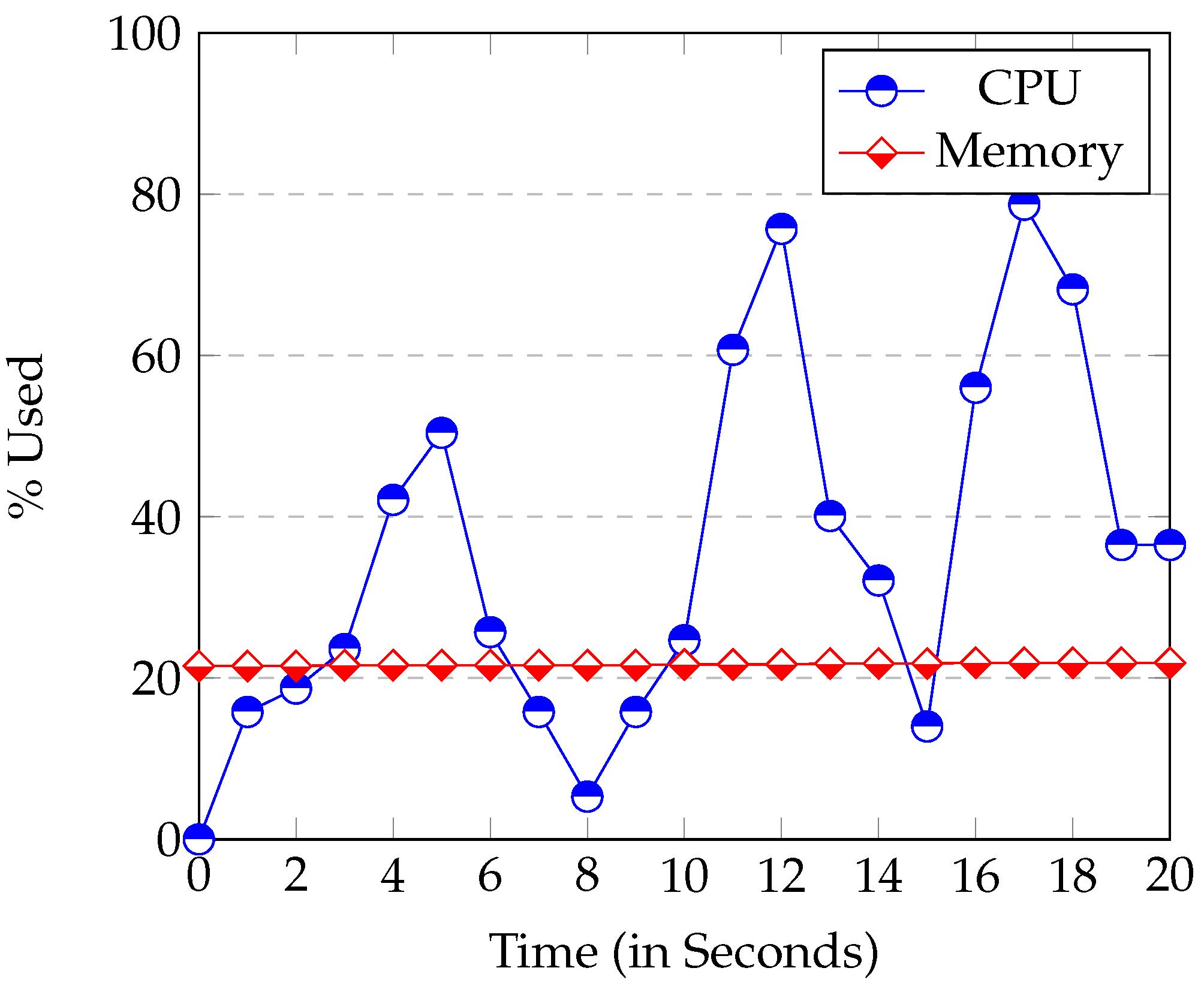
The node Node.js uses considerably more CPU than the Raspberry at start up. Its execution usually reached 50% of CPU or more (see Figure 6). This high CPU usage is caused by the loading and start up of modules. All modules are loaded at the beginning of the application. It can be seen in Figure 6 that the start-up time in the Raspberry was between 15–20 s. The start up time of the server instead (executed in a laptop), was never longer than 5 s. So, the start-up time is bounded by the device speed.
Figure 6.
Raspberry CPU and Memory Usage at server’s start up.

The Memory used at start-up is proportional to the modules used and the database size. Once the start-up phase has been completed, the occupation of the CPU drops sharply to nearly 0%. In other words, the CPU usage of Node.js is minimum when it is waiting for an event.
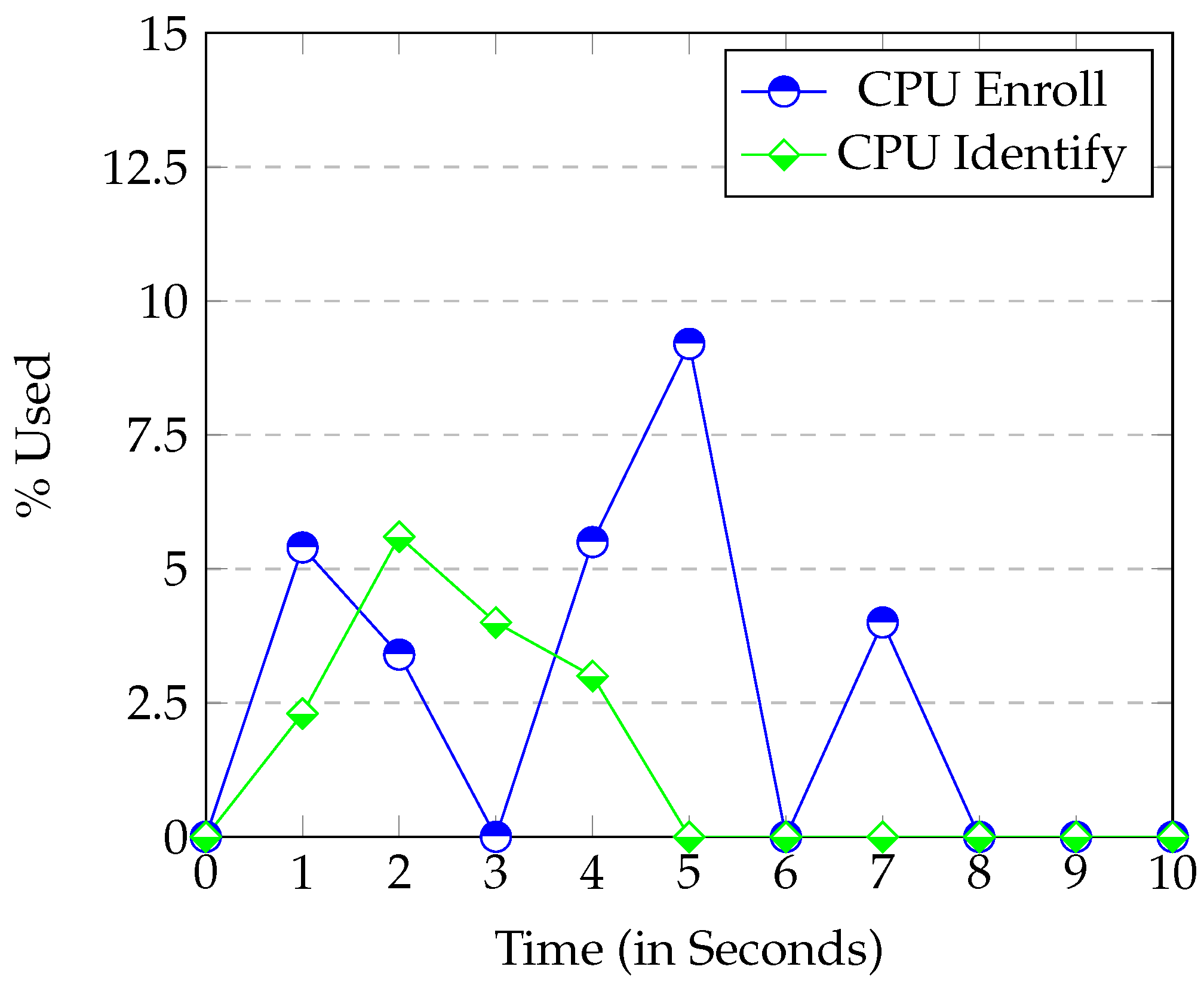
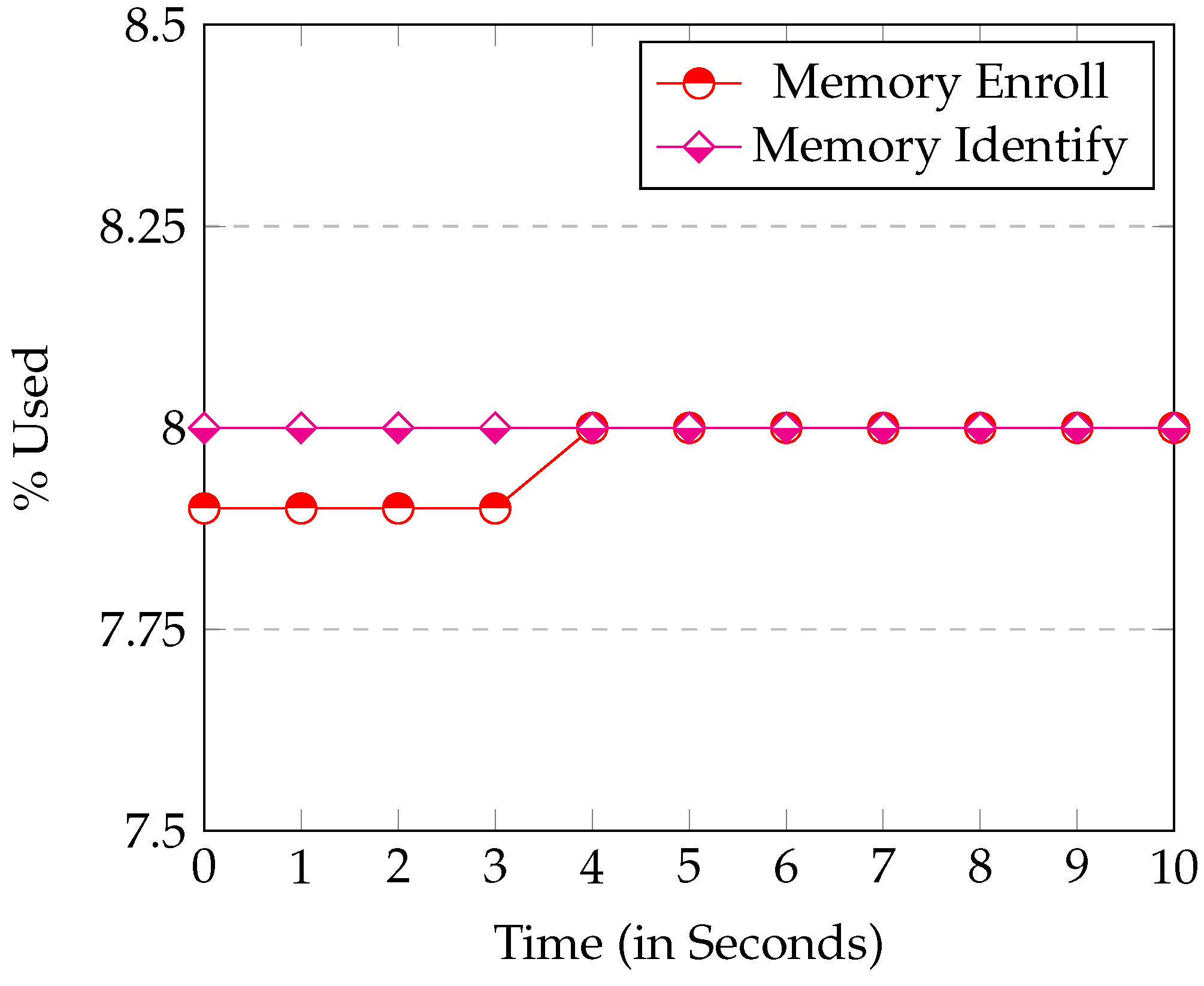
Figure 7 and Figure 8 show the CPU and Memory usage respectively in the Identify and Enroll processes. Node.js consumes little Memory or CPU. When Enroll saves a new fingerprint entry in the SQLite database, the Memory used only increases by 0.2%. This result confirms that SQLite database is really small. Thus, it is perfect for systems with limited Memory (like ours). The graph also shows the CPU when the server is communicating with the device. In this case, you can see that the CPU use is always under 12%, so once again, the Raspberry executed the web server perfectly.
Figure 7.
CPU usage when the Enroll and Identify process are called.

Figure 8.
Memory Usage by the Enroll and Identify processes.

In conclusion, the behavior of the server performance running on the Raspberry embedding device worked well. The Raspberry has many hardware limitations (μprocessor ARMv5 and only 1GB of RAM Memory), but this embedded system behaved perfectly as a web server. The only drawback was its high elapsed time at start up.
5.4. Client
In this section the response times of the different URIs are evaluated in different web browsers, running on a PC. The client, executing in a Epiphany browser, installed in the Raspberry was also tested.
5.4.1. Client Running in the Raspberry
In this section, the Epiphany browser (default browser in Raspberry) is evaluated. This browser has to be executed jointly with the Windows system (in the graphic mode) of the Raspberry.
Figure 9 shows the CPU and Memory usage when the client application (Angular.js) of the Epiphany browser is executed in the Raspberry.
Figure 9.
CPU and Memory Usage when the client is executed in the Raspberry.
It can be observed that the CPU and Memory used increased greatly in Figure 9 compared with Figure 6. When the Raspberry browser runs the Angular.js client, it consumes a lot of CPU and Memory resources. This can drastically drop both website (client) and device management (server) performance. The Raspbian operating system needs to load the X11 Windows system. Thus, it is much better to run the client in another device other than the Raspberry with more CPU and Memory. Thus, connecting a screen to the Raspberry and executing both the client and the server inside it would not be a good choice.
5.4.2. Choosing a Browser for the Client
This section will evaluates the behavior of a client when running on a PC or laptop because, as we have seen before, executing it in the Raspberry (Epiphany browser) is not a good option.
We analyzed the execution performance of the Angular.js client application in the compatible browsers Google Chrome, Mozilla Firefox, Opera, Epiphany and Midori. The most significant difference between them was the CSS (Cascading Style Sheet) used. However, the CCS used did not affect performance at all.
We measured the response time in sending a request and receiving an answer packet from the server. The request chosen was GET domain/fingerprints because it is the one that transmits more information, and thus performance differences can be more easily appreciated. Table 5 shows the mean times obtained in each browser when the request was executed 10 times. Firefox gave the best results. Surprisingly, it was one order of magnitude faster than the remaining 3. This difference can cause significant delays in the overall system. So, gains from choosing Firefox can even overcome the choice of more expensive devices.
| Chrome | Firefox | Opera | Midori | Epiphany | |
|---|---|---|---|---|---|
| Time (in ms) | 36 | 22 | 32 | 30 | 38 |
5.5. Precision and Recall Analysis
In this section, fingerprint recognition was evaluated. In doing so, the Precision, Recall and F scores were used, which are based on the following fingerprint sampling possibilities:
- True positive (tp): a user registered in the database puts a finger on the scanner and the system recognizes him/her.
- False positive (fp): an unregistered user puts a finger on the scanner and the system recognizes him/she.
- True negative (tn): an unregistered user puts a finger on the scanner and the scanner does not recognizes him/her.
- False negative (fn): a user registered in the database puts a finger on the scanner but the system does not recognizes him/her.
Table 6 and Table 7 show the results obtained with 100 trials. Table 6 shows the results obtained with 15 users registered in the database (50 random trials were made), so only true positives and false negatives were sampled. The results obtained were satisfactory. The application answered the 74% of the trials correctly. Table 7 shows the true negatives and false positives obtained also with 50 trials but, in this occasion randomly chosen between 15 unregistered users. As can be seen, the system never failed. It achieved a 100% success rate. Based on these results, the Precision and Recall were 1 and 0.74 respectively. Keeping in mind the low-cost of the system implemented, these results demonstrate its high performance in accordance with the Precision and Recall. These two indices are close to 1. In the case of Precision, that is equal to 1, the best possible result.
| True Positives | False Negatives | Total Trials |
|---|---|---|
| 37 | 13 | 50 |
| True Negatives | False Positives | Total Trials |
|---|---|---|
| 50 | 0 | 50 |
Once Precision and Recall have been defined, it is important to calculate the F score. F (defined in Eequation (3)) is a metric that gives a harmonic mean of Precision and Recall. F scores also range between [0…1]. Also, the best values are closer to 1.
Returning to our example, by applying the Equation (3), an F score of 0.85 was obtained. As 0.85 is very close to 1, it can be said that the obtained F was a good score.
5.6. ROC Curve
We also obtained the ROC curve of the system performance with 10 users (see Table 8). Half of them are genuine and the others are impostors. With these users a different number of trials were carried out. Attempts per user were ten times its order on the list. For example, User 1 (User 10) performed 1 × 10 = 10 (10 × 10 = 100) attempts. Users 1, 2, 5, 6 and 10 were genuine users and the remaining ones were impostors. Column Success1 shows the results obtained when the system failed (0) and when it never failed (1). We considered a system fault to be when it gave at least one false positive or when half the trials were false negatives. Column Success2 considered it a system fault only when it gave at least one false positive.
| User | Attempts | Success1 | Success2 |
|---|---|---|---|
| User 1 | 10 | 0 | 0 |
| User 2 | 20 | 0 | 0 |
| User 3 | 30 | 1 | 1 |
| User 4 | 40 | 1 | 1 |
| User 5 | 50 | 1 | 1 |
| User 6 | 60 | 0 | 1 |
| User 7 | 70 | 1 | 1 |
| User 8 | 80 | 1 | 1 |
| User 9 | 90 | 1 | 1 |
| User 10 | 100 | 1 | 1 |
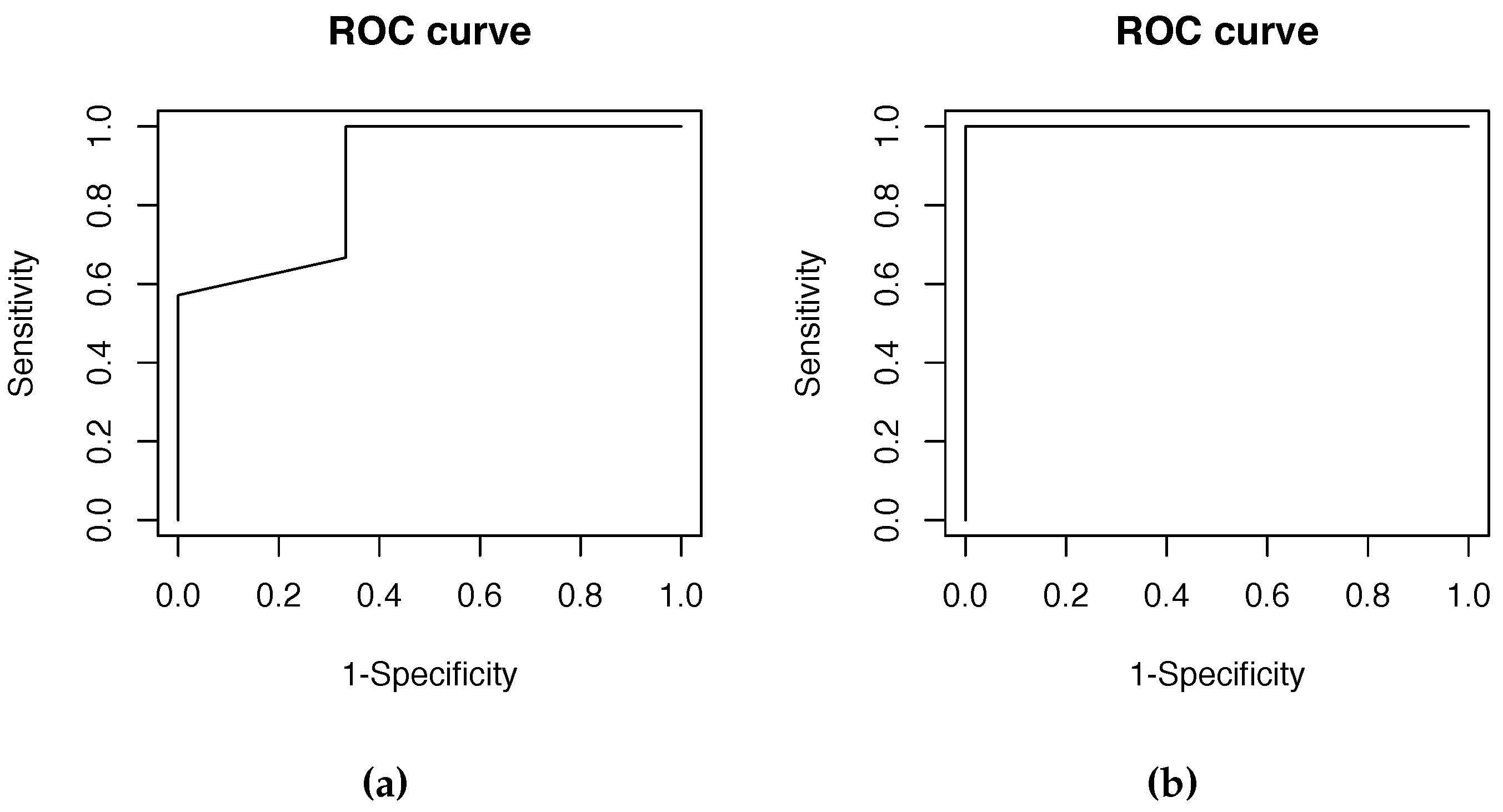
Figure 10a,b show the ROC curve for the Success1 and Success2 cases respectively. These results were excellent. In the Success1 case, we evaluated any kind of system error, and so it is obvious that there was more chance of error than in Succcess2. However, the score was very satisfactory (Area Under the Curve, AUC = 0.87). Note that in the Success2 case, we evaluated the effectiveness when the system denied access to unauthorized users. In this occasion, the behavior obtained was perfect (AUC = 1). However, we can say that the scores in both cases were excellent. So we can conclude that the FingerScanner system presented works properly.
Figure 10.
ROC curves. (a) ROC curve Success1; (b) ROC curve Success2.

6. Conclusions and Future Work
The conclusions are based on the project results. The results were good and proved that FingerScanner could be embedded in a commercial product.
The system architecture is well designed. It allows connections to the FingerScanner from different devices. The front-end (client) can be executed in any computer or mobile devices with a browser. Functionality is easily extensible. These features make the FingerScanner system robust and flexibile.
The serial communication server device is slow (115,200 baud). However, it is acceptable, as it does not greatly penalize the overall system performance. It must be said that the scanner device was a good choice, because it gives a good efficiency/cost relation, provided that the sensor is in a static position. In addition, the finger recognition success rate of the FingerScanner system obtained an F score of 0.85.
The Raspberry hardware in this project is robust, and it works properly. Its viability was carefully tested, because the CPU and Memory of the Raspberry have several restrictions in computational power and capacity, respectively. However, the CPU behaved properly for its service requirements. Furthermore, the FingerScanner application fit in the Raspberry Memory very well.
The website (client) security should be improved, for example, by using the https protocol and iptablesscripting, so the system will become safer. The transmission of information should also be encrypted. Node.js and Angular.js have modules like crypto to encrypt. Thread concurrency issues must also be solved by using event-driven controllers, for example.
Acknowledgments
This work was supported by the MEyC under contracts TIN2011-28689-C02-02 and TIN2014-53234-C2-2-R. The authors are members of the research group 2014-SGR163, funded by the Generalitat de Catalunya. Besides, this research was partly supported by the European Union FEDER (CAPAP-H5network TIN2014-53522-REDT).
Author Contributions
Jordi Sapes performed the design and the implementation of FingerScanner. He also carried out the experimentation. Francesc Solsona supervised all of the process. He wrote the paper and designed the experiments.
Conflicts of Interest
The authors declare no conflict of interest.
References
- Hackadai.io. Available online: https://hackaday.io/projects/tag/raspberry%20pi (accessed on 29 August 2015).
- Node Raspberry Pi alarm. Available online: https://hackaday.io/project/6390-node-pi-alarm (accessed on 29 August 2015).
- Chowdhury, N.; Nooman, S.; Sarker, S. Access Control of Door and Home Security by Raspberry Pi Through Internet. Int. J. Sci. Eng. Res. 2013, 4, 550–558. [Google Scholar]
- Bahrudin, B.; Kassim, R.A.; Buniyamin, N. Development of Fire Alarm System using Raspberry Pi and Arduino Uno. In Proceedings of the International Conference on Electrical, Electronics and System Engineering (ICEESE), Kuala Lumpur, Malaysia, 4–5 December 2013; pp. 43–48.
- Karagoez, M.F.; Turgut, C. Design and Implementation of RESTful Wireless Sensor Network Gateways Using Node.js Framework. In Proceedings of the 20th European Wireless Conference, Barcelona, Spain, 14–16 May 2014; pp. 1–6.
- Banerjee, S.; Sethia, D.; Mittal, T.; Arora, U.; Chauhan, A. Secure Sensor Node with Raspberry Pi. In Proceedings of the International Conference on Multimedia, Signal Processing and Communication Technologies (IMPACT-2013), Aligarh, India, 23–25 November, 2013; pp. 26–30.
- Sowmiya, U.; Mansoor, J.S. Raspberry Pi based home door security through 3g dongle. Int. J. Eng. Res. Gener. Sci. 2015, 3, 138–144. [Google Scholar]
- Prasad, S.; Mahalakshmi, P.; Sunder, A.J.; Swathi, R. Smart Surveillance Monitoring System Using Raspberry PI and PIR Sensor. Int. J. Comput. Sci. Inf. Technol. 2014, 5, 7107–7109. [Google Scholar]
- Kumar, K.S.; Thomas, J.; Alex, J.; Malhotra, R. Surveillance System Based on Raspberry Pi for Monitoring a Location through a Mobile Device. Int. J. Adv. Multidiscip. Res. 2015, 2, 103–108. [Google Scholar]
- Kanaga, D.; Raja, S.; Viswanathan, C.; Sivakumar, D.; Vikekanandan, M. Secure Smart Home Energy Monitoring System. J. Theor. Appl. Inf. Technol. 2014, 66, 305–314. [Google Scholar]
- Sandeep, V.; Gopal, K.L.; Naveen, S.; Amudhan, A.; Kumar, L.S. Globally accessible machine automation using Raspberry Pi based on Internet of Things. In Proceedings of the International Conference on Advances in Computing, Communications and Informatics (ICACCI 2015), Kochi, India, 10–13 August 2015; pp. 1144–1147.
- Chen, C.; Pai, T.; Cheng, M. A Support Vector Machine Approach for Truncated Fingerprint Image Detection from Sweeping Fingerprint Sensors. Sensors 2015, 15, 7807–7822. [Google Scholar] [CrossRef] [PubMed]
- Janard, K.; Marurngsith, W. Accelerating real-time face detection on a raspberry pi telepresence robot. In Proceedings of the Fifth International Conference on Innovative Computing Technology (INTECH 2015), Vigo, Spain, 20–22 May 2015; pp. 136–141.
- Leccesse, F.; Cagnetti, M. An Intelligent and High Efficiency Street Lighting System Isle Based on Raspberry-Pi Card, ZigBee Sensor Network and Photovoltaic Energy. Int. J. Eng. Sci. Innov. Technol.-IJESIT 2014, 3, 274–285. [Google Scholar]
- Cagnetti, M.; Leccese, F.; Trinca, D. A New Remote and Automated Control System for the Vineyard Hail Protection Based on ZigBee Sensors, Raspberry-Pi Electronic Card and WiMAX. J. Agric. Sci. Technol. 2013, 3, 853–864. [Google Scholar]
- Moure, D.; Torres, P.; Casas, B.; Toma, D.; Blanco, M.J.J.; del Río, J.; Manuel, A. Use of Low-Cost Acquisition Systems with an Embedded Linux Device for Volcanic Monitoring. Sensors 2015, 15, 20436–20462. [Google Scholar] [CrossRef] [PubMed] [Green Version]
- Nikhade, S.G. Wireless sensor network system using Raspberry Pi and zigbee for environmental monitoring applications. In Proceedings of the International Conference on Sin Smart Technologies and Management for Computing, Communication, Controls, Energy and Materials (ICSTM 2015), Chennai, India, 6–8 May 2015; pp. 376–381.
- Paramanathan, A.; Pahlevani, P.; Thorsteinsson, S.; Hundeboll, M.; Lucani, D.E.; Fitzek, F. Sharing the Pi: Testbed Description and Performance Evaluation of Network Coding on the Raspberry Pi. In Proceedings of the 79th IEEE Vehicular Technology Conference (VTC Spring 2014), Seoul, Korea, 18–21 May 2014; pp. 1–5.
© 2016 by the authors; licensee MDPI, Basel, Switzerland. This article is an open access article distributed under the terms and conditions of the Creative Commons by Attribution (CC-BY) license (http://creativecommons.org/licenses/by/4.0/).
Share and Cite
MDPI and ACS Style
Sapes, J.; Solsona, F. FingerScanner: Embedding a Fingerprint Scanner in a Raspberry Pi. Sensors 2016, 16, 220. https://doi.org/10.3390/s16020220
AMA Style
Sapes J, Solsona F. FingerScanner: Embedding a Fingerprint Scanner in a Raspberry Pi. Sensors. 2016; 16(2):220. https://doi.org/10.3390/s16020220
Chicago/Turabian StyleSapes, Jordi, and Francesc Solsona. 2016. "FingerScanner: Embedding a Fingerprint Scanner in a Raspberry Pi" Sensors 16, no. 2: 220. https://doi.org/10.3390/s16020220
Note that from the first issue of 2016, this journal uses article numbers instead of page numbers. See further details here.