
New C4D Sensor with a Simulated Inductor

State Key Laboratory of Industrial Control Technology, College of Control Science and Engineering, Zhejiang University, Hangzhou 310027, China
*
Author to whom correspondence should be addressed.
Sensors 2016, 16(2), 165; https://doi.org/10.3390/s16020165
Submission received: 9 December 2015
/
Revised: 9 January 2016
/
Accepted: 22 January 2016
/
Published: 27 January 2016
(This article belongs to the Section Physical Sensors)
Abstract
:A new capacitively coupled contactless conductivity detection (C4D) sensor with an improved simulated inductor is developed in this work. The improved simulated inductor is designed on the basis of the Riordan-type floating simulated inductor. With the improved simulated inductor, the negative influence of the coupling capacitances is overcome and the conductivity measurement is implemented by the series resonance principle. The conductivity measurement experiments are carried out in three pipes with different inner diameters of 3.0 mm, 4.6 mm and 6.4 mm, respectively. The experimental results show that the designs of the new C4D sensor and the improved simulated inductor are successful. The maximum relative error of the conductivity measurement is less than 5%. Compared with the C4D sensors using practical inductors, the measurement accuracy of the new C4D sensor is comparable. The research results also indicate that the adjustability of a simulated inductor can reduce the requirement for the AC source and guarantee the interchangeableness. Meanwhile, it is recommended that making the potential of one terminal of a simulated inductor stable is beneficial to the running stability. Furthermore, this work indirectly verifies the possibility and feasibility of the miniaturization of the C4D sensor by using the simulated inductor technique and lays a good foundation for future research work.
1. Introduction
Electrical conductivity is a key parameter of electrolyte solution. The on-line measurement of conductivity is of great importance to academic research and industrial applications [1,2,3,4]. Up to date, the conventional conductivity measurement techniques have mainly been based on contact conductivity detection. The direct contact between the electrodes and the solution may cause the polarization effect and the electrochemical reaction [5,6,7,8,9,10,11,12,13]. Meanwhile, the electrode contamination may bring about unpredictable measurement error. These drawbacks limit the applications of the contact conductivity detection technique.
The capacitively coupled contactless conductivity detection (C4D) technique is a capillary electrophoresis (CE) alternative conductivity detection method [5,6,7,8,9,10,11,12,13,14,15,16,17,18,19,20,21,22,23,24,25,26,27,28,29,30,31,32,33,34,35]. Its measurement principle can be briefly illustrated by Figure 1. As shown in Figure 1a, the construction of a typical C4D sensor includes two cylindrical metal electrodes fixed around the outside of an insulating pipe, an AC source and a current pick-up unit. Figure 1b shows the equivalent circuit of the typical C4D sensor. and are the coupling capacitances between the electrodes and the solution through the pipe wall. and are the electrical double-layer capacitances. is the stray capacitance. is the solution capacitance and is the resistor of the solution between the two electrodes. Research works have indicated that [3,7,8,9,10,11,12,13,14,15,16,17,18,19,20,21,22,23,24,25,26,27,28,31,32,33,34,35]: (1) The electrical double-layer capacitances and are in series with the coupling capacitances and . The values of and are much larger than that of and . Because the capacitance resulting from a series combination of large and small capacitances is determined essentially by the small capacitance, and can be ignored. (2) The solution capacitance is in parallel with the solution resisitor . is of a very small order of magnitude (i.e., the impedance of is much larger than that of in an AC path). Because the impedance resulting from a parallel combination is determined essentially by the small one, the influence of can be ignored. Thus, the influences of the electrical double-layer capacitances ( and ) and the solution capacitance on the conductivity measurement are not significant and can be neglected. Additionally, the equivalent circuit Figure 1b can be simplified to Figure 1c which is the commonly used equivalent circuit in the C4D research field [7,8,9,10,11,12,17,18,20,21,22,23,24,25,26,27,31,32,33,34,35]. Meanwhile, research works have also verified that the negative influence of the stray capacitance can be overcome by introducing a grounded plane/shield [7,8,9,10,11,20,21,22,23,24,25,26,27,28]. Thus, the equivalent circuit Figure 1c can be further simplified to Figure 1d. In this work, Figure 1d is used for the following electrical circuit analysis and discussion because a grounded shield is introduced into our new C4D senor. When the AC source is applied, the current (which reflects the information of the solution resistor ) flows through the AC path to the current pick-up unit, and then the conductivity measurement is implemented.
Figure 1.
Principle of a typical C4D sensor: (a) Construction; (b) Equivalent circuit; (c) Simplified equivalent circuit; (d) Further simplified equivalent circuit.
Figure 1.
Principle of a typical C4D sensor: (a) Construction; (b) Equivalent circuit; (c) Simplified equivalent circuit; (d) Further simplified equivalent circuit.
Obviously, C4D is a contactless detection method. The polarization effect and the electrochemical reaction, which exist in the contact conductivity detection, can be avoided. So, the C4D technique has received considerable attention of scientists and engineers since it appeared [5,6,7,8,9,10,11,12,13,14,15,16,17,18,19,20,21,22,23,24,25,26,27,28,29,30,31,32,33,34,35]. However, to date, C4D has mainly been studied and applied in the research field of analytical chemistry for ion concentration/conductivity detection in a capillary [5,6,7,8,9,10,11,12,13,14,15,16,17,18,19,20,21,22,23,24,25,26,27,28,29,30,31,32,33,34,35]. It is still a developing technique, and its resolution and detection range should be improved. As shown in Figure 1d, in the view of electrical impedance measurement, only the resistor is the useful signal. Although the existence of the coupling capacitances and makes the contactless conductivity detection possible, the impedances of and are background signals which cause the loss of linearity and limit the resolution and the detection range of conductance detection [6,7,8,9,10,11,12,13,16,17,18,19,20,26,27,28,29,30,31,32,33,34,35].
To suppress the negative influence of the coupling capacitances, some methods have been proposed. The high-frequency method is a commonly used approach which reduces the influence of the coupling capacitances on the conductivity measurement by increasing the excitation frequency [6,7,8,9,10,11,12,13]. However, despite its usefulness, the application of the high-frequency method may cause higher requirements for the AC source and the design of the electronic circuit, and the stray capacitance is a problem which must be considered. Laugere et al. studied a four-electrode C4D sensor in which the solution measurement is realized by a differential voltage signal [17,18,30]. However, the construction is relatively complicated. Shih et al. and Zheng et al. reported a new method which is based on the parallel resonance principle [31,32]. At the resonant frequency, the negative influence of the coupling capacitances and the stray capacitance can be eliminated. Unfortunately, the resonant frequency of the circuit is related to the resistor and is difficult to determine. Kang et al. used the series inductance from a piezoelectric quartz crystal to compensate the conductance from and [33,34,35]. This method can effectively improve the sensitivity and the signal-to-noise ratio. However, it is mainly applied in capillaries and the operating frequency is relatively high [33,34,35]. Therefore, although many technical achievements have been obtained, more studies should be undertaken.
Currently, our research group has also made some efforts in this area and a new method on the basis of the series resonance principle is proposed [26,27,28]. Figure 2 is the simplified circuit of the C4D sensor based on series resonance, where is a practical inductor connected into the AC path in series. At resonance (the resonant frequency is determined by ), the capacitive reactance of the coupling capacitances will be eliminated by the inductive reactance of the inductor. The reactance of the overall impedance of the detection circuit can be zero and the overall impedance only consists of the resistor which is the useful signal. Our research works have verified that with the introduction of a practical inductor, the negative influence of the coupling capacitances can be overcome, the measurement performance of the C4D sensor can be improved, and the C4D sensor can successfully implement the conductivity detection in millimeter-scale pipes [26,27,28].
Figure 2.
Simplified circuit of the C4D sensor based on series resonance.
However, due to the non-adjustable characteristic of a practical inductor, the C4D sensor based on series resonance still has its drawbacks: (1) To implement the conductivity measurement, the frequency of the AC source should be adjusted to the resonant frequency. The resonant frequency is dependent on the inductance value of the practical inductor. For a practical inductor, it is not easy to adjust its inductance value. So, the non-adjustable characteristic of the practical inductor may cause an additional requirement for the AC source, and limit (or narrow) the selection range of the AC source; (2) The non-adjustable characteristic of the practical inductor more or less limits the interchangeableness of the C4D sensor and, hence, causes inconvenience for the practical application of the C4D sensor. For example, if we hope one detection circuit can be interchangeable in different C4D sensors with different inner diameters when the excitation frequency is difficult to adjust or one C4D sensor can work at different resonant frequencies, one practical inductor is not enough and different practical inductors with different inductance values should be used to implement the resonance. Therefore, if we can seek a useful approach to overcome the non-adjustable characteristic of a practical inductor, the C4D sensor based on series resonance may have broader application perspective.
Fortunately, the emergence of a simulated inductor technique provides an attractive solution. As we know, according to the current technique level, it is relatively simple to reduce the dimensions of resistors, capacitances and operational amplifiers, while it is difficult to reduce the size of practical inductors [36,37,38]. Meanwhile, it is difficult to implement large-valued inductors [38,39,40,41,42]. The simulated inductor is developed and studied to satisfy the need for small-size inductors in integrated circuits. A simulated inductor is implemented by using active and/or passive components (such as resistors, capacitances and operational amplifiers) and it can function effectively to replace a practical inductor in a circuit [36,37,38]. Compared with the practical inductor, the advantages of the simulated inductor are adjustable inductance value, small size, wider range of inductance values and so on [36,37,38,39,40,41,42,43,44,45]. Currently, the simulated inductor is mainly studied and applied in integrated circuits. Our experience or knowledge on the application of the simulated inductor technique to other research fields is limited.
The aim of this work is to design an improved simulated inductor which is suitable for the C4D sensor based on series resonance and, hence, to develop a new C4D sensor. With the improved simulated inductor, the new C4D sensor can overcome the influence of the non-adjustable characteristic of a practical inductor on conductivity measurement.
2. Design of New C4D Sensor
2.1. Improved Simulated Inductor
The improved simulated inductor is designed on the basis of the Riordan-type floating simulated inductor which is a classic and typical simulated inductor [36,42,44]. Figure 3 shows the circuit of the improved simulated inductor. Compared with the standard Riordan-type floating simulated inductor, the differences (or improvements) of this improved simulated inductor are as follows:
- Considering the practical applications, to avoid the output saturation of the operational amplifiers and , two resistors and are added between the inverting input and the output of the operational amplifiers and , respectively.
- The resistor is adjustable while it is an invariable resistor in the Riordan-type floating simulated inductor circuit. This modification is to make the equivalent inductance of the improved simulated inductor adjustable.
Figure 3.
Circuit of the improved simulated inductor.
Let , , , , . The impedance of the improved simulated inductor can be described as
The equivalent inductance of the improved simulated inductor is
The internal resistance of the improved simulated inductor is
In this work, to adjust the equivalent inductance conveniently, is chosen as an adjustable resistor, while the values of the other resistors and capacitances (, , and ) are fixed. Thus, the equivalent inductance can be adjusted by changing the value of the adjustable resistor .
2.2. New C4D Sensor
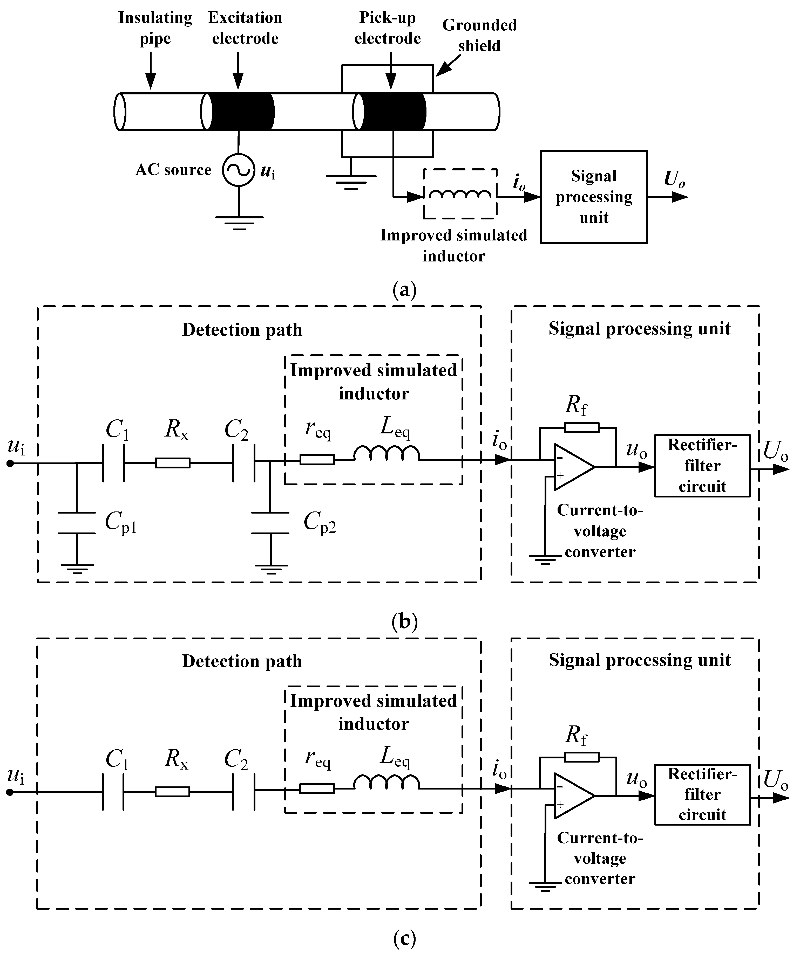
Figure 4 shows the measurement principle of the new C4D sensor. Figure 4a is the construction of the new C4D sensor, including an AC source, an insulating pipe, two cylindrical metal electrodes, the improved simulated inductor, a grounded shield and a signal processing unit. The signal processing unit has two parts: a current-to-voltage converter and a rectifier-filter circuit. The improved simulated inductor is introduced to overcome the negative influence of the coupling capacitances.
Figure 4.
Measurement principle of the new C4D sensor: (a) Construction; (b) Equivalent circuit; (c) Simplified equivalent circuit.
Figure 4.
Measurement principle of the new C4D sensor: (a) Construction; (b) Equivalent circuit; (c) Simplified equivalent circuit.

Figure 4b illustrates the equivalent circuit of the new C4D sensor, where is the stray capacitance arising between the excitation electrode and the grounded shield, is the stray capacitance arising between the pick-up electrode and the grounded shield, and is the feedback resistance. Research works have verified that the stray capacitances and are very small and their influences can be neglected [20,26,27,28]. Thus, Figure 4b can be simplified to Figure 4c.
The overall impedance of the detection path is
where is the excitation frequency of the AC source. According to the series resonance principle, at the resonant frequency , the inductive reactance and the capacitive reactance can be eliminated by each other and the reactance of the total impedance is zero. The resonant frequency is determined by
Thus, the overall impedance at resonance is
Equation (6) shows that, at the resonant frequency , the influence of the coupling capacitances and can be overcome, the overall impedance only consists of the resistance elements, the resistor of the solution and the internal resistance of the improved simulated inductor . is a background signal. The existence of may, more or less, cause unfavorable influence on the linearity.
Furthermore, it is necessary to indicate that the reason why the improved simulated inductor is connected between the pick-up electrode and the signal processing unit (not connected between the AC source and the excitation electrode) is based on the consideration of the running stability of the simulated inductor. The components (resistors, capacitances and operational amplifiers) of the improved simulated inductor are not ideal. Additionally, the improved simulated inductor is a relatively complicated multi-closed-loop system. As we know, for a practical closed-loop system, its running stability is a problem which should be carefully considered. If the potentials of both terminals of the improved simulated inductor are unceasingly changing, it may bring some undesirable effects into the running stability of the improved simulated inductor. If the potential of one terminal could be stable, it can not only help to improve the running stability, but also help to reduce the requirement for the relevant detection circuit. As shown in Figure 4b, the output of the improved simulated inductor is connected to the inverting input of an operational amplifier (the input of the current-to-voltage converter in the signal processing unit). That means the potential of one terminal of the improved simulated inductor is stable. So, in this work, the improved simulated inductor is connected between the pick-up electrode and the signal processing unit.
3. Experimental Results and Discussion
3.1. Experimental Results
To test the performance of the new C4D sensor with the improved simulated inductor, the conductivity measurement experiments were carried out. Figure 5 illustrates the experimental setup for conductivity measurement. In the experiments, the insulating pipes were glass pipes. The electrodes were two rings of silver paint over the glass pipes. Three new C4D sensors with different inner diameters (3.0 mm, 4.6 mm and 6.4 mm, respectively) were tested. Table 1 lists the parameters of the three new C4D sensors. KCl solution was used as the experimental electrolyte solution and a syringe pump (Syringe Pump Model 33, HARVARD Apparatus Inc., Holliston, MA, USA, 0 mL/min~60 mL/min, ±0.35% full scale (F.S.)) was used to drive the solution into the pipe. A commercial device (cDAQ9172, National Instruments Inc., Austin, TX, USA) was used as the data acquisition unit. The reference conductivity data were obtained by a commercial contact conductivity meter (FE30, Meter Toledo Inc., Greifensee, Switzerland, 0.00 µS/cm~199.9 mS/cm, ±0.5% F.S.). The experimental temperature was around 25 °C. For the three new C4D sensors with different inner diameters, the improved simulated inductor was the same (its equivalent inductance value was adjusted to 53.0 mH). The components information in the improved simulated inductor circuit were: , , , , , the value of the adjustable resistor ranges from 0 to 10.0 kΩ, and are Multilayer Ceramic Capacitor (MLCC), the amplifiers (~) are AD825 (Analog Devices, Inc., Norwood, MA, USA).
Figure 5.
Experimental setup for conductivity measurement.

| New C4D Sensor | Length of the Electrodes (mm) | Length of the Gap (mm) | Excitation Frequency (kHz) |
|---|---|---|---|
| 3.0 mm i.d. 1 (5.0 mm o.d. 2) | 15.0 | 15.0 | 164.8 |
| 4.6 mm i.d. (7.0 mm o.d.) | 23.0 | 23.0 | 151.7 |
| 6.4 mm i.d. (8.5 mm o.d.) | 32.0 | 32.0 | 134.8 |
1 inner diameter; 2 outer diameter.
The relative error was adopted to assess the conductivity detection performance of the new C4D sensor, which is defined as
where is the measurement conductivity value obtained by the new C4D sensor and is the reference conductivity value.
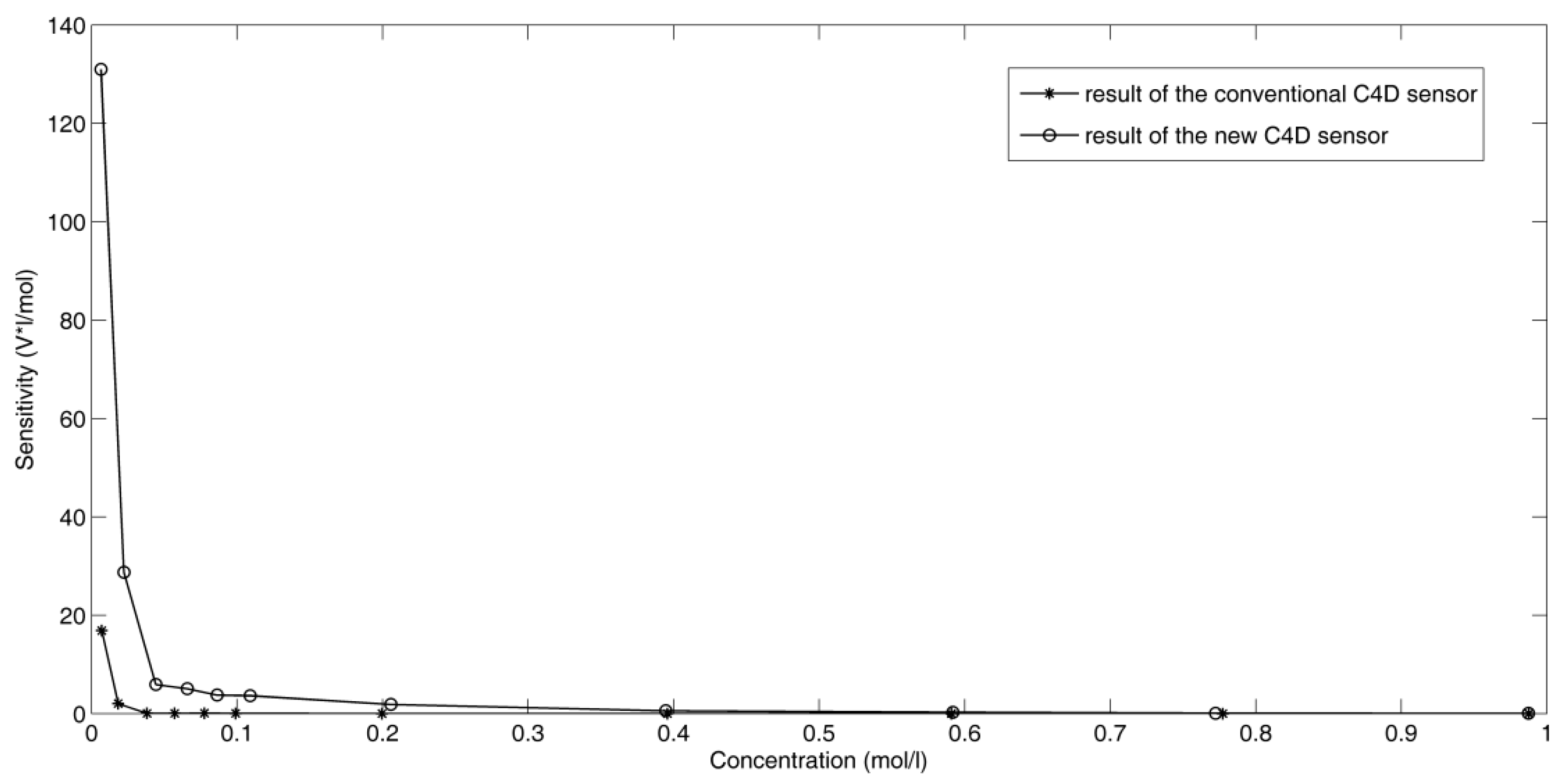
Figure 6 shows the experimental results of the three new C4D sensors. Compared with the commercial contact conductivity meter, the maximum relative errors of the three new sensors are all less than 5%. Compared with the C4D sensors using practical inductors [26,27,28], the measurement accuracy of the new C4D sensor with the improved simulated inductor is comparable. Figure 7 shows the sensitivity plots of the new C4D sensor with 3.0 mm i.d. and the conventional C4D sensor with 3.0 mm i.d. Compared with the conventional C4D sensor, the performance of the new C4D sensor is better. Meanwhile, the sensitivity plots show that both sensitivities of the new C4D sensor and the conventional C4D sensor are not constant. At lower concentration, the sensitivities are relatively high while at higher concentration the sensitivities are low. Generally, the sensitivities of the new C4D sensor and the conventional C4D sensor decrease with the increase of concentration (or conductivity). The experimental results are in accordance with other researchers’ study results [12,21,22,23,24,34]. The research results indicate that the designs of the new C4D sensor and the improved simulated inductor are successful. The improved simulated inductor is suitable for the C4D sensor based on series resonance and the measurement performance of the new C4D sensor is satisfactory.
Figure 6.
Conductivity measurement results of three new C4D sensors: (a) 3.0 mm i.d.; (b) 4.6 mm i.d.; (c) 6.4 mm i.d.
Figure 6.
Conductivity measurement results of three new C4D sensors: (a) 3.0 mm i.d.; (b) 4.6 mm i.d.; (c) 6.4 mm i.d.
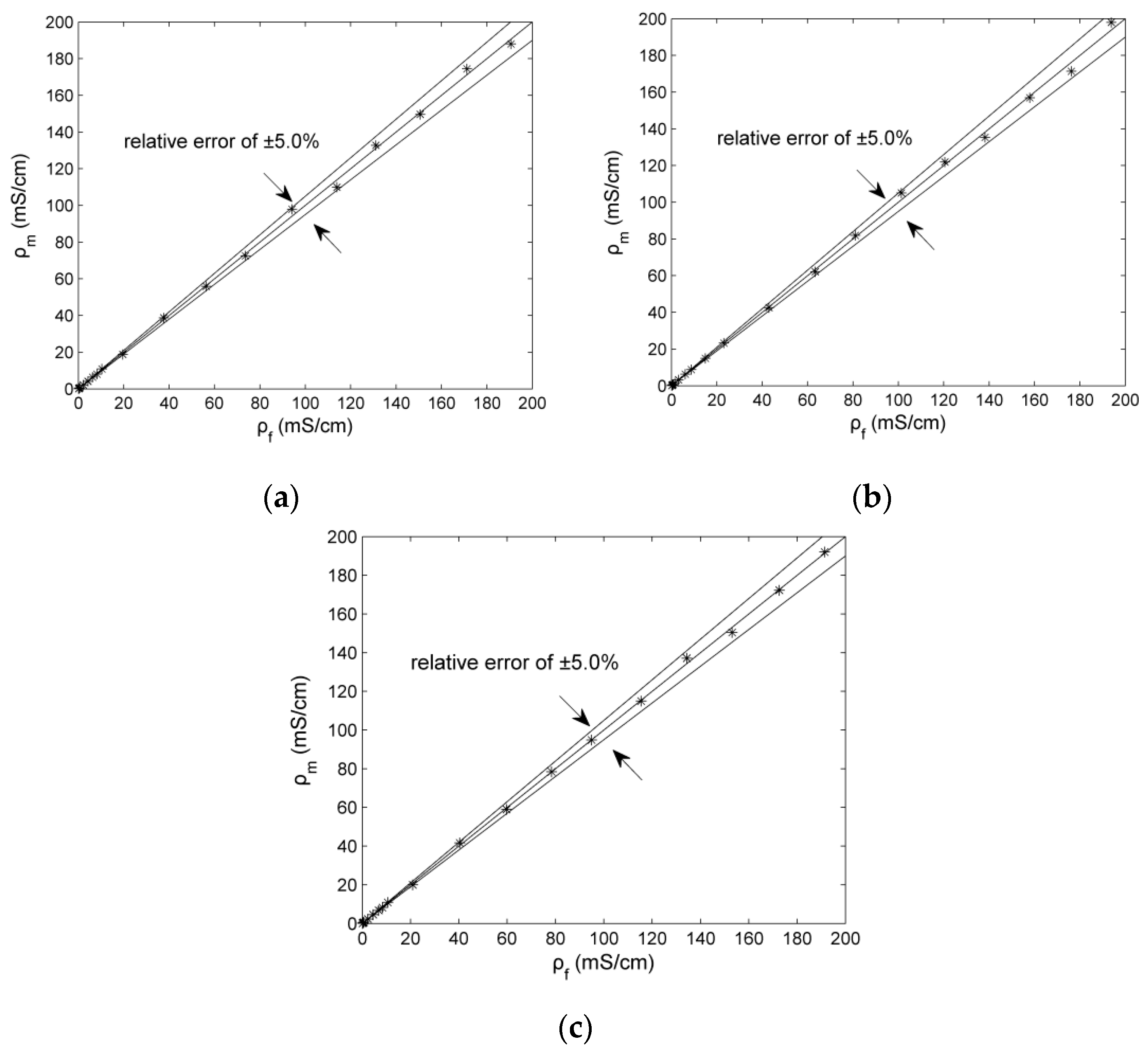
Figure 7.
Sensitivity plots of the new C4D sensor with 3.0 mm i.d. and the conventional C4D sensor with 3.0 mm i.d.
Figure 7.
Sensitivity plots of the new C4D sensor with 3.0 mm i.d. and the conventional C4D sensor with 3.0 mm i.d.

As mentioned in Section 2, the equivalent inductance value of the improved simulated inductor can be adjustable by changing the value of the adjustable resistor . To test the adjustability of the improved simulated inductor, the relevant experiments are also performed. The test results indicate that the equivalent inductance value of the improved simulated inductor can be successfully changed from 28.8 mH to 74.1 mH by adjusting from 2.27 kΩ to 6.23 kΩ. This capability of the improved simulated inductor can greatly reduce the requirement for the AC source and is beneficial for guaranteeing the interchangeableness of the new C4D sensor.
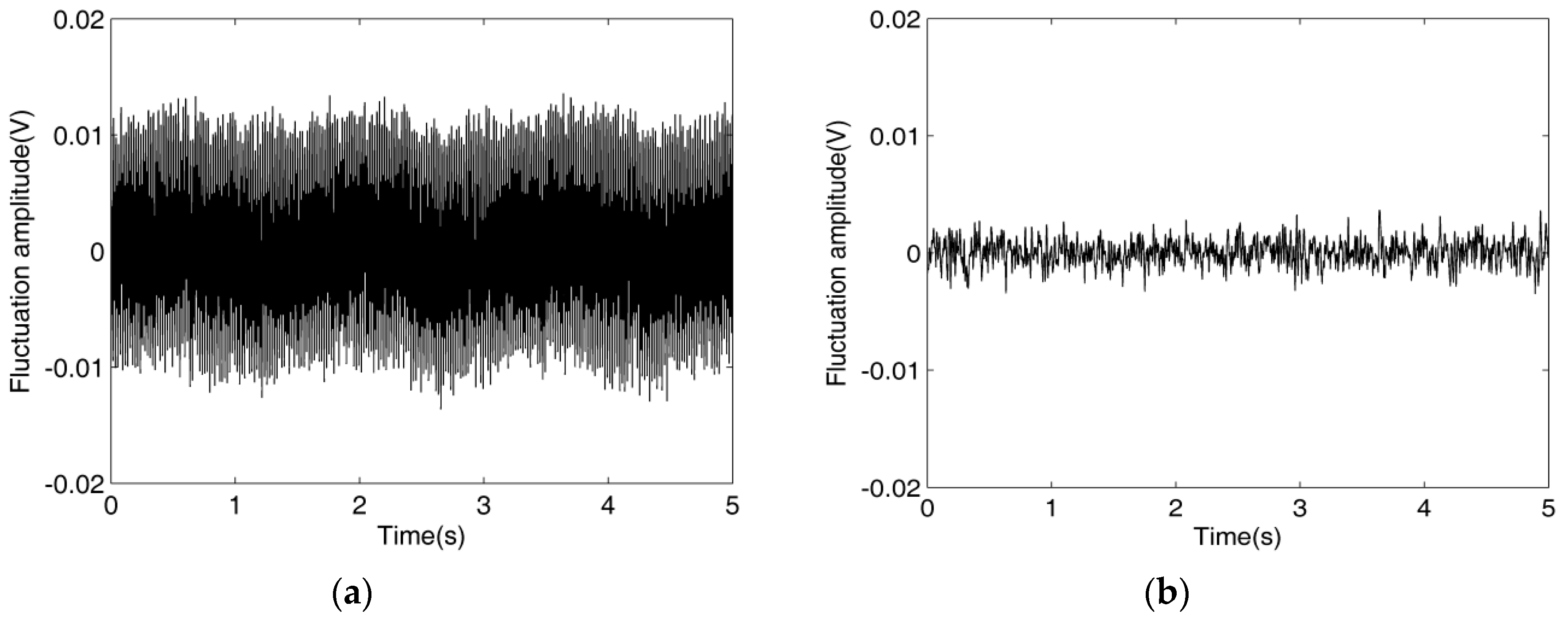
In addition, to test the reasonableness of the connection method of the improved simulated inductor, a supplementary C4D sensor was developed and a special comparison experiment was carried out. Figure 8 shows the construction of the supplementary C4D sensor. Compared with Figure 4a, obviously, unlike the new C4D sensor, in the supplementary C4D sensor the improved simulated inductor is connected between the AC source and the excitation electrode. Figure 9 shows the output signals of the new C4D sensor with 3.0 mm i.d. and the supplementary C4D sensor with 3.0 mm i.d. It is clear that the signal fluctuation amplitude of the supplementary C4D sensor is greater than that of the new C4D sensor. The special comparison experimental result indicates that, although the supplementary C4D sensor can implement the conductivity measurement, its running stability is obviously worse than that of the new C4D sensor. This experimental result verifies that our consideration of the running stability of the simulated inductor is reasonable. The connection method in the new C4D sensor (the improved simulated inductor is connected between the pick-up electrode and the signal processing unit) is a wise choice.
Figure 8.
Construction of the supplementary C4D sensor.
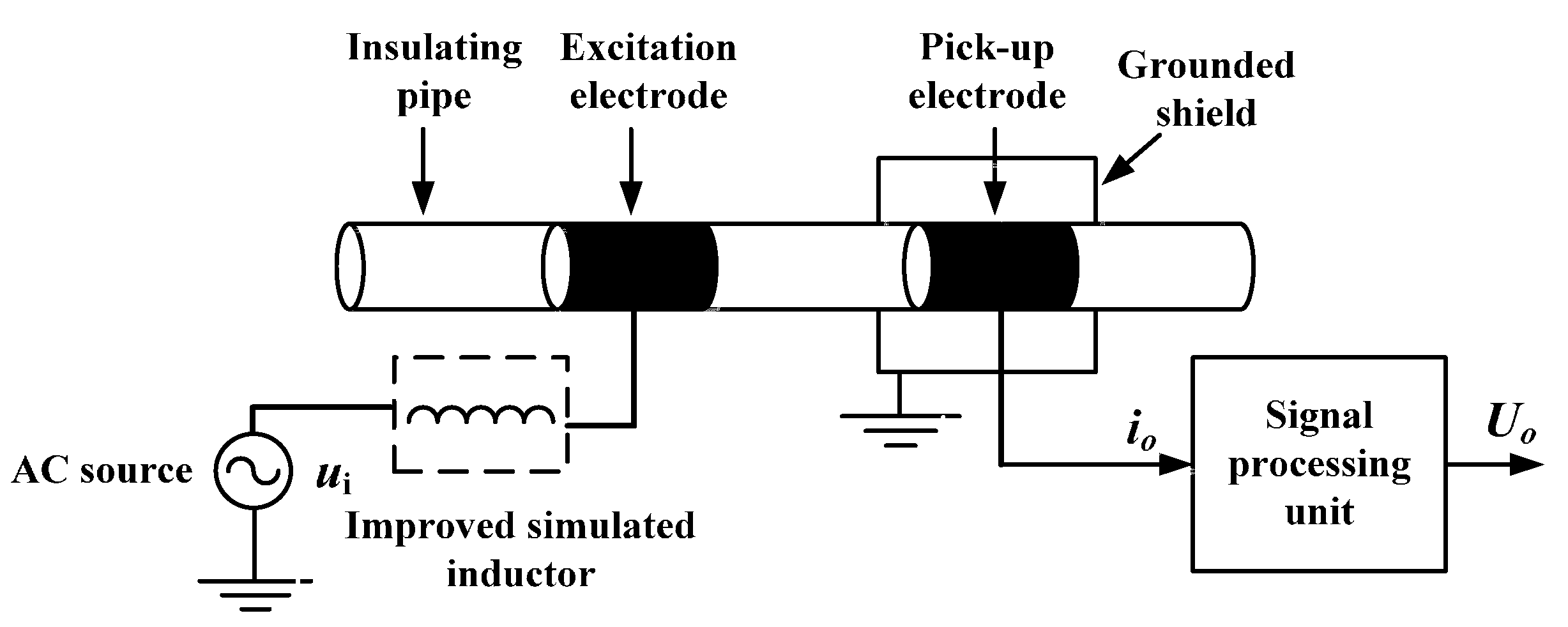
Figure 9.
Output signals: (a) Supplementary C4D with 3.0 mm i.d.; (b) New C4D sensor with 3.0 mm i.d.
Figure 9.
Output signals: (a) Supplementary C4D with 3.0 mm i.d.; (b) New C4D sensor with 3.0 mm i.d.
3.2. Discussion
The research results in this work have proved that the equivalent inductance value of a successfully designed simulated inductor can be adjusted in a relatively wide range (e.g., in this work, the equivalent inductance value of the improved simulated inductor can be changed from 28.8 mH to 74.1 mH by adjusting from 2.27 kΩ to 6.23 kΩ.). However, the adjustment range of the practical adjustable inductor is usually less than 15%. So, the simulated inductor technique indeed provides a useful approach to overcome the non-adjustable characteristic of a practical inductor. The adjustability of a simulated inductor is not only beneficial to the design of a sensor, but is also convenient for guaranteeing the interchangeableness of the sensor and its practical applications.
Meanwhile, the research results also indicate that a simulated inductor is a relatively complicated closed-loop system and its components (resistors, capacitances and operational amplifiers) are not ideal. The running stability is really a problem which should be carefully considered. According to our comparison experimental result, it is recommended that making the potential of one terminal of a simulated inductor stable is beneficial to the running stability.
Furthermore, the miniaturization of the C4D sensor has become an attractive research area and many researchers have made their efforts in this area [5,7,8,9,10,17,18,30]. It is necessary to indicate that, although the aim of this work is not the miniaturization of the C4D sensor, the research results can provide a useful reference. As we know, the practical inductor is usually a spiral inductor and its miniaturization is very difficult [36,37,38,39,40,41,42]. Unlike a practical inductor, the miniaturization of the components (resistors, capacitances and operational amplifiers) used in a simulated inductor are easy to implement [36,38,39,40]. This work actually indirectly verifies the possibility and feasibility of the miniaturization of the C4D sensor by using the simulated inductor technique and lays a good foundation for future research work.
4. Conclusions
In this work, the simulated inductor technique is introduced into the research field of C4D. Based on the Riordan-type floating simulated inductor, an improved simulated inductor is designed to overcome the non-adjustable characteristic of a practical inductor. With the improved simulated inductor, a new C4D sensor, which implements the conductivity measurement by the series resonance principle, is developed.
Three new C4D sensors with different inner diameters (3.0 mm, 4.6 mm and 6.4 mm, respectively) have been evaluated experimentally. The conductivity measurement results demonstrate that the design of the improved simulated inductor is effective and the new C4D sensor is successful. Compared with a commercial contact conductivity meter, the maximum relative error of the new C4D sensor is less than 5%. Compared with the C4D sensors using practical inductors, the measurement performance of the new C4D sensor is comparable.
The test experimental results show that the equivalent inductance value of the improved simulated inductor can be adjusted in a relatively wide range, compared with a practical inductor. Due to the adjustability of the improved simulated inductor, it is easier for the new C4D sensor to implement the conductivity measurement and the requirement for the AC source is reduced. The research results also indicate that making the potential of one terminal of a simulated inductor stable is beneficial to the running stability.
This research work verifies the effectiveness and feasibility of the application of the simulated inductor technique to the design of a new C4D sensor. Meanwhile, this research work expands the application fields of the simulated inductor technique and lays a good foundation for the miniaturization and integration of the C4D sensor in the future.
Acknowledgments
This work is supported by National Natural Science Foundation of China (No.51476139).
Author Contributions
Yingchao Lyu and Haifeng Ji conducted the experiments, analyzed the signals and wrote the manuscript; Zhiyao Huang, Baoliang Wang, Shijie Yang and Haiqing Li provided suggestions about the work and helped to modify the manuscript. All authors read and approved the final manuscript.
Conflicts of Interest
The authors declare no conflict of interest.
References
- Tower, O.F. The Conductivity of Liquids: Methods, Results, Chemical Applications and Theoretical Considerations; Chemical Publishing Company: Easton, PA, USA, 1905. [Google Scholar]
- De Diego, A.; Usobiaga, A.; Fernandez, L.A.; Madariaga, J.M. Application of the electrical conductivity of concentrated electrolyte solutions to industrial process control and design: From experimental measurement towards prediction through modeling. Trends. Anal. Chem. 2001, 20, 65–78. [Google Scholar] [CrossRef]
- Bard, A.J.; Faulkner, L.R. Electrochemical Methods Fundamentals and Application; John Wiley & Sons, Inc.: New York, NY, USA, 2001. [Google Scholar]
- Hamann, C.H.; Hamnett, A.; Vielstich, W. Electrochemistry, 2nd ed.; Wiley-VCH Verlag GmbH & Co.KGaA: Weinheim, Germany, 2007. [Google Scholar]
- Pumera, M. Contactless conductivity detection for microfluidics: Designs and applications. Talanta 2007, 74, 358–364. [Google Scholar] [CrossRef] [PubMed]
- Gas, B.; Demjanenko, M.; Vacik, J. High-frequency contactless conductivity detection in isotachophoresis. J. Chromatogr. A 1980, 192, 253–257. [Google Scholar] [CrossRef]
- Kuban, P.; Hauser, P.C. A review of the recent achievements in capacitively coupled contactless conductivity detection. Anal. chim. Acta 2008, 607, 15–29. [Google Scholar] [CrossRef] [PubMed]
- Kuban, P.; Hauser, P.C. Ten years of axial capacitively coupled contactless conductivity detection for CZE—A review. Electrophoresis 2009, 30, 176–188. [Google Scholar] [CrossRef] [PubMed]
- Coltro, W.K.T.; Lima, R.S.; Segato, T.P.; Carrilho, E.; de Jesus, D.P.; do Lago, C.L.; da Silva, J.A.F. Capacitively coupled contactless conductivity detection on microfluidic systems—Ten years of development. Anal. Methods 2012, 4, 25–33. [Google Scholar] [CrossRef]
- Kuban, P.; Hauser, P.C. Contactless conductivity detection for analytical techniques—Developments from 2012 to 2014. Electrophoresis 2015, 36, 195–211. [Google Scholar] [CrossRef] [PubMed]
- Gas, B.; Zuska, J.; Coufal, P.; van de Goor, T. Optimization of the high-frequency contactless conductivity detector for capillary electrophoresis. Electrophoresis 2002, 23, 3520–3527. [Google Scholar] [CrossRef]
- Opekar, F.; Tuma, P.; Stulik, K. Contactless impedance sensors and their application to flow measurements. Sensors 2013, 13, 2786–2801. [Google Scholar] [CrossRef] [PubMed]
- Kuban, P.; Hauser, P.C. Capacitively coupled contactless conductivity detection for microseparation techniques—Recent developments. Electrophoresis 2011, 32, 30–42. [Google Scholar] [CrossRef] [PubMed]
- Reilley, C.N. Fundamentals of Electrode Processes. In Treatise on Analytical Chemistry; Kolthoff, I.M., Elving, P.J., Eds.; Interscience Publishers: New York, NY, USA, 1963; Part 1; Volume 4, pp. 2109–2160. [Google Scholar]
- West Loveland, J. Conductometry and Oscillometry. In Treatise on Analytical Chemistry; Kolthoff, I.M., Elving, P.J., Eds.; Interscience Publishers: New York, NY, USA, 1963; Part 1; Volume 4, pp. 2569–2630. [Google Scholar]
- Coltro, W.K.T.; de Santis Neves, R.; de Jesus Motheo, A.; da Silva, J.A.F.; Carrilho, E. Microfluidic devices with integrated dual-capacitively coupled contactless conductivity detection to monitor binding events in real time. Sens. Actuators B Chem. 2014, 192, 239–246. [Google Scholar] [CrossRef]
- Laugere, F.; Lubking, G.W.; Berthold, A.; Bastemeijer, J.; Vellekoop, M.J. Downscaling aspects of a conductivity detector for application in on-chip capillary electrophoresis. Sens. Actuators A Phys. 2001, 92, 109–114. [Google Scholar] [CrossRef]
- Laugere, F.; Guijt, R.M.; Bastemeijer, J.; van der Steen, G.; Berthold, A.; Baltussen, E.; Sarro, P.; van Dedem, G.W.K.; Bossche, A. On-chip contactless four-electrode conductivity detection for capillary electrophoresis devices. Anal. Chem. 2003, 75, 306–312. [Google Scholar] [CrossRef] [PubMed]
- Zemann, A.J.; Schnell, E.; Volgger, D.; Bonn, G.K. Contactless conductivity detection for capillary electrophoresis. Anal. Chem. 1998, 70, 563–567. [Google Scholar] [CrossRef] [PubMed]
- Da Silva, J.A.F.; do Lago, C.L. An oscillometric detector for capillary electrophoresis. Anal. Chem. 1998, 70, 4339–4343. [Google Scholar] [CrossRef]
- Kuban, P.; Hauser, P.C. Fundamental aspects of contactless conductivity detection for capillary electrophoresis, part I: Frequency behavior and cell geometry. Electrophoresis 2004, 25, 3387–3397. [Google Scholar] [CrossRef] [PubMed]
- Kuban, P.; Hauser, P.C. Fundamental aspects of contactless conductivity detection for capillary electrophoresis, part II: Signal-to-noise ratio and stray capacitance. Electrophoresis 2004, 25, 3398–3405. [Google Scholar] [CrossRef] [PubMed]
- Brito-Neto, J.G.A.; da Silva, J.A.F.; Blanes, L.; do Lago, C.L. Understanding capacitively coupled contactless conductivity detection in capillary and microchip electrophoresis, part 1. Fundamentals. Electroanalysis 2005, 17, 1198–1206. [Google Scholar] [CrossRef]
- Brito-Neto, J.G.A.; da Silva, J.A.F.; Blanes, L.; do Lago, C.L. Understanding capacitively coupled contactless conductivity detection in capillary and microchip electrophoresis, part 2. Peak shape, stray capacitance, noise, and actual electronics. Electroanalysis 2005, 17, 1207–1214. [Google Scholar] [CrossRef]
- Cahill, B.P.; Land, R.; Nacke, T.; Min, M.; Beckmann, D. Contactless sensing of the conductivity of aqueous droplets in segmented flow. Sens. Actuators B Chem. 2011, 159, 286–293. [Google Scholar]
- Huang, Z.Y.; Jiang, W.W.; Zhou, X.M.; Wang, B.L.; Ji, H.F.; Li, H.Q. A new method of capacitively coupled contactless conductivity detection based on series resonance. Sens. Actuators B Chem. 2009, 143, 239–245. [Google Scholar] [CrossRef]
- Huang, Z.Y.; Long, J.; Xu, W.B.; Ji, H.F.; Wang, B.L.; Li, H.Q. Desigen of capacitively coupled contactless conductivity detecion sensor. Flow Meas. Instrum. 2012, 27, 67–70. [Google Scholar] [CrossRef]
- Wang, L.; Huang, Z.Y.; Wang, B.L.; Ji, H.F.; Li, H.Q. Flow pattern identification of gas-liquid two-phase flow based on capacitively coupled contactless conductivity detection. IEEE Trans. Instrum. Meas. 2012, 61, 1466–1475. [Google Scholar] [CrossRef]
- Gillespie, E.; Connolly, D.; Macka, M.; Hauser, P.; Paull, B. Development of a contactless conductivity detector cell for 1.6 mm OD (1/16th inch) HPLC tubing and micro-bore columns with on-column detection. Analyst 2008, 133, 1104–1110. [Google Scholar] [CrossRef] [PubMed]
- Laugere, F.; Lubking, G.W.; Bastemeijer, J.; Vellekoop, M.J. Design of an electronic interface for capacitively coupled four-electrode conductivity detection in capillary electrophoresis microchip. Sens. Actuators B Chem. 2002, 83, 104–108. [Google Scholar] [CrossRef]
- Shih, C.Y.; Li, W.; Zheng, S.Y.; Tai, Y.C. A resonance-induced sensitivity enhancement method for conductivity sensors. In Proceedings of the 5th IEEE Conference on Sensors, Daegu, Korea, 22–25 October 2006; pp. 271–274.
- Zheng, S.Y.; Nandra, M.S.; Shih, C.Y.; Li, W.; Tai, Y.C. Resonance impedance sensing of human blood cells. Sens. Actuators A Phys. 2008, 145, 29–36. [Google Scholar] [CrossRef]
- Kang, Q.; Shen, D.Z.; Li, Q.L.; Hu, Q.; Dong, J.F.; Du, J.G.; Tang, B. Reduction of the impedance of a contactless conductivity detector for microchip capillary electrophoresis: Compensation of the electrode impedance by addition of a series inductance from a piezoelectric quartz crystal. Anal. Chem. 2008, 80, 7826–7832. [Google Scholar] [CrossRef] [PubMed]
- Shen, D.Z.; Li, D.D.; Yang, X.W.; Zhu, Y.; Dong, J.F.; Kang, Q. Application of a low impedance contactless conductometric detector for the determination of inorganic cations in capillary monolithic column chromatography. Talanta 2011, 84, 42–48. [Google Scholar] [CrossRef] [PubMed]
- Shen, D.Z.; Li, Y.L.; Zhang, Z.L.; Zhang, P.; Kang, Q. Determination of amino acids by capillary electrophoresis with differential resonant contactless conductivity detector. Talanta 2013, 104, 39–43. [Google Scholar] [CrossRef] [PubMed]
- Kumar, U.; Shukla, S.K. Analytical study of inductor simulation circuits. Act. Passive Electron. Compon. 1989, 13, 211–227. [Google Scholar] [CrossRef]
- Andriesei, C.; Goraş, L. On the tuning possibilities of an RF bandpass filter with simulated inductor. In Proceedings of the International Semiconductor Conference, Sinaia, Romania, 15–17 October 2007; pp. 489–492.
- Yuce, E.; Minaei, S.; Cicekoglu, O. Limitations of the simulated inductors based on a single current conveyor. IEEE Trans. Circuits. Syst. I Reg. Papers 2006, 53, 2860–2867. [Google Scholar] [CrossRef]
- Yuan, F. CMOS Active Inductors and Transformers: Principle, Implementation, and Applications; Springer Science & Business Media: New York, NY, USA, 2008. [Google Scholar]
- Fakhfakh, M.; Pierzchała, M.; Rodanski, B. On the design of active inductors with current-controlled voltage sources. Analog Digit. Signal Process. 2012, 73, 89–98. [Google Scholar] [CrossRef]
- Antoniou, A. Realisation of gyrators using operational amplifiers, and their use in RC-active-network synthesis. IEEE Proc. 1969, 116, 1838–1850. [Google Scholar] [CrossRef]
- Riordan, R.H.S. Simulated inductors using differential amplifiers. Electron. Lett. 1967, 3, 50–51. [Google Scholar] [CrossRef]
- Dutta Roy, S.C. A circuit for floating inductance simulation. IEEE Proc. 1974, 62, 521–523. [Google Scholar] [CrossRef]
- Christiansen, D.; Alexander, C.; Jurgen, R. Standard Handbook of Electronic Engineering, 5th ed.; McGraw Hill Professional: Boston, MA, USA, 2004. [Google Scholar]
- Yuce, E.; Minaei, S.; Cicekoglu, O. A novel grounded inductor realization using a minimum number of active and passive components. ETRI J. 2005, 27, 427–432. [Google Scholar] [CrossRef]
© 2016 by the authors; licensee MDPI, Basel, Switzerland. This article is an open access article distributed under the terms and conditions of the Creative Commons by Attribution (CC-BY) license (http://creativecommons.org/licenses/by/4.0/).
Share and Cite
MDPI and ACS Style
Lyu, Y.; Ji, H.; Yang, S.; Huang, Z.; Wang, B.; Li, H. New C4D Sensor with a Simulated Inductor. Sensors 2016, 16, 165. https://doi.org/10.3390/s16020165
AMA Style
Lyu Y, Ji H, Yang S, Huang Z, Wang B, Li H. New C4D Sensor with a Simulated Inductor. Sensors. 2016; 16(2):165. https://doi.org/10.3390/s16020165
Chicago/Turabian StyleLyu, Yingchao, Haifeng Ji, Shijie Yang, Zhiyao Huang, Baoliang Wang, and Haiqing Li. 2016. "New C4D Sensor with a Simulated Inductor" Sensors 16, no. 2: 165. https://doi.org/10.3390/s16020165
Note that from the first issue of 2016, this journal uses article numbers instead of page numbers. See further details here.