Article

Secure and Efficient Key Coordination Algorithm for Line Topology Network Maintenance for Use in Maritime Wireless Sensor Networks

1
Optical Fibre Sensors Research Centre, Department of Electronic and Computer Engineering, University of Limerick, Limerick V94 T9PX, Ireland
2
Mobile and Marine Robotics Research Centre, Department of Electronic and Computer Engineering, University of Limerick, Limerick V94 T9PX, Ireland
*
Author to whom correspondence should be addressed.
Sensors 2016, 16(12), 2204; https://doi.org/10.3390/s16122204
Submission received: 14 November 2016 / Revised: 6 December 2016 / Accepted: 19 December 2016 / Published: 21 December 2016
(This article belongs to the Section Sensor Networks)

Abstract

:
There has been a significant increase in the proliferation and implementation of Wireless Sensor Networks (WSNs) in different disciplines, including the monitoring of maritime environments, healthcare systems, and industrial sectors. It has now become critical to address the security issues of data communication while considering sensor node constraints. There are many proposed schemes, including the scheme being proposed in this paper, to ensure that there is a high level of security in WSNs. This paper presents a symmetric security scheme for a maritime coastal environment monitoring WSN. The scheme provides security for travelling packets via individually encrypted links between authenticated neighbors, thus avoiding a reiteration of a global rekeying process. Furthermore, this scheme proposes a dynamic update key based on a trusted node configuration, called a leader node, which works as a trusted third party. The technique has been implemented in real time on a Waspmote test bed sensor platform and the results from both field testing and indoor bench testing environments are discussed in this paper.

1. Introduction

Recent advances in Wireless Sensor Networks (WSNs) have meant that sensor nodes are capable of processing and transmitting environmental monitored data in real time to end users who are located far from the area covered by the sensor network. WSNs are still limited however in terms of energy, memory storage, and security communication capabilities. Fortunately, security for WSNs has been examined and developed upon for different application domains, such as medical and environmental. It has been shown by Mathur et al. in [1] that it is possible to provide a patient monitoring system that resolves security issues associated with data loss, while in [2] Elgenaidi et al. have studied different water environment monitoring systems based on WSNs that carry information that has value, and this value (data) must be encrypted for protection. The security of transmitted data is crucial in WSN applications so as not to reveal to unauthorized persons the information travelling between nodes, however this security solution must be resource-friendly and efficient. In order to build an efficient security algorithm, it is necessary to fully understand the process of security functions in terms of energy consumption, time execution and code size.
In WSN mesh networks, symmetric encryption algorithms have been widely used because of the advantages of low cost with respect to power consumption, time execution and code size. The main obstruction in the implementation of symmetric encryption is the issue of key re-distribution between nodes in the case of a change in the network members. Asymmetric encryption techniques, such as Rivest, Shamir, and Adleman (RSA) and elliptic curve cryptography (ECC) have been used to tackle re-keying in WSNs applications [3], however, the problem with using these techniques is the computation overhead on every node in the network, and this increases the cost of each node and accordingly the processing of security key management. Generally, key management in sensor networks can be listed under three headings:
  • Key Transport/Distribution where one sensor node creates and securely transfers it to the others.
  • Key Agreement where the key is established by a shared secret between two or more nodes.
  • Key pre-distribution where keys are distributed before the sensor nodes are deployed. Moreover, key management can be performed using trusted third party devices such as trusted servers, authentication servers, key distribution centers (KDCs) key translation centers (KTCs), and certification authorities (CAs) [4,5,6].
Some applications rely upon a secure key establishment mechanism where each node in a key establishment protocol is able to determine the true identity of the other nodes that could possibly gain access to the resulting key. This implies the preclusion of any unauthorized additional parties from deducing the same key [5]. Many secure key management schemes which promote longer battery life also depend on the type of system.
The most widely used wireless standard for WSNs is IEEE 802.15.4 [7]. The main advantages of using IEEE 802.15.4 are very low energy consumption, the capability of using different network topologies, for instance point-to-point topology the capability of inter-operability with transmit/receive chips, such as XBee 802.15.4 pro and the ability to engage with Wi-Fi.
The scheme being proposed in this paper addresses the main issues in security mechanisms based on the symmetric encryption algorithm, including memory, storage space, key generation, and re-keying. In this paper, the deployment of a Waspmote sensor node integrated with the XBee 802.15.4 pro module in an outdoor environment using IEEE 802.15.4/2.4 GHz standard will be used to demonstrate the implementation of the proposed protocol. Most of the presented results to date by other authors [8,
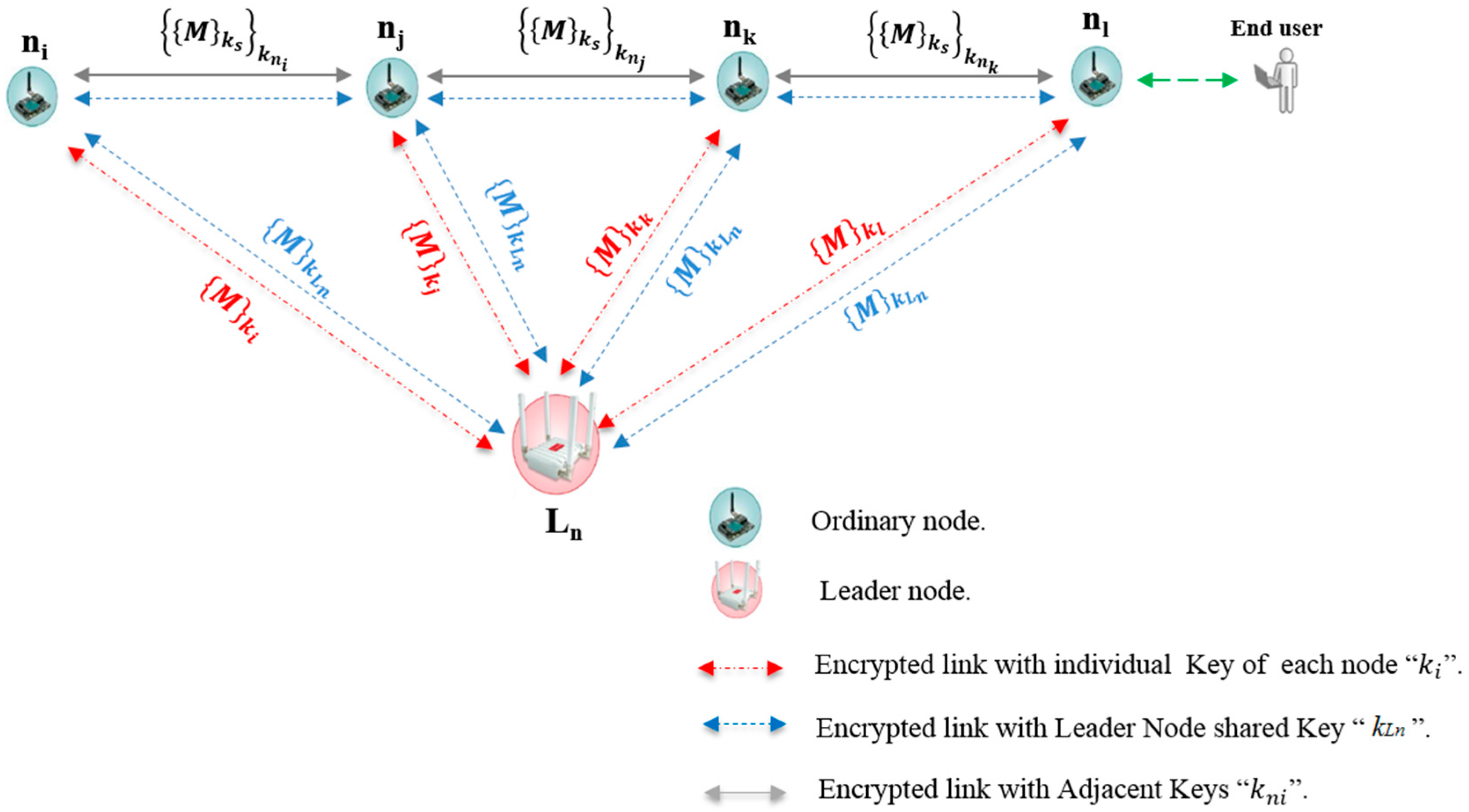
9] have been obtained using simulators and not real deployments as in this paper. This paper also presents a security mechanism suitable for marine coastal monitoring, where each node in a line topology sends packets encrypted with its secret key, called the Adjacent key, to provide data confidentiality. This key is shared only with an authorized neighbor in the network. Furthermore, the re-keying phase in the revocation process will be a partly operation coordinated by a node called the leader node.
The rest of this paper is organized as follows: related works are discussed in Section 2. In Section 3 the proposed technique is discussed covering network topology, platform, travelling packets, packet structure, and security and key management. It also describes transmission security and data encryption, Re-keying and the memory requirement for the scheme. In Section 4, the outdoor implementation and performance measurements of the scheme are also presented in different scenarios. These measurements are discussed in terms of the received single strength indicator (RSSI), the average round trip time (RTT) and current consumption. In Section 5 a discussion and comparison between measurements of the proposed scheme and results of other schemes is given. The paper is concluded in Section 6.

2. Related Work

There are some well-known practices for developing efficient trust security systems for WSNs and managing the cryptographic keys in order to protect WSNs from malicious attacks [10]. Liu, et al. proposed in [11] an efficient and simple technique for detecting selective forwarding attacks and recovering the failed route based on a per-hop acknowledgement. This section will present key management and encryption schemes, which ensure the level of security in WSNs application.
Liebeherr et al. [
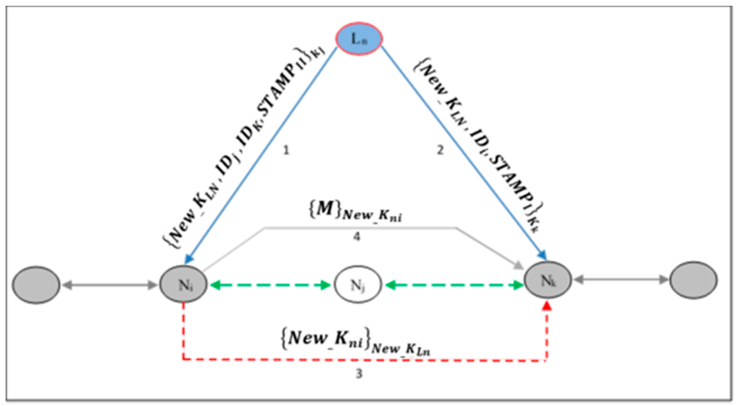
12] designed and implemented a security key management and encryption scheme called the ‘neighborhood key’ scheme. This technique provided integrity and confidentiality for application data in overlay networks. The core mechanism of this technique was to avoid network-wide re-keying operations. Additionally, the scheme re-encrypts the payload data at each forwarding hop. Moreover, the neighborhood key method provided a solution for protection against routing attacks, where authentication between sensor nodes in the network depends on the certificate signed by a trusted third party using an X.509 Version 3 certificate. Each sensor node in the network had its own signed certificate, also each node stores the certificates of one or more trusted third party. In this scheme the authentication phase was performed without coordination with other nodes. The node certificate included a secret key, which is used to encrypt or sign data. Sensor nodes exchange certificates after receiving a message protocol from another node in the network. Once the certificates are exchanged, the encryption of data and the signing of hashes in each node will be done with a single symmetric key called a ‘neighborhood key’. Thus, the neighborhood keys are shared between current authenticated neighbors in the network. In the joining phase where a new node joins the network, a new neighborhood key must be generated and sent to all of its authenticated neighbors in order to maintain confidentiality in the network.
Furthermore, updating and exchanging a new neighborhood key is executed whenever the set of authenticated neighbors are changed or the specified maximum lifetime of the current neighborhood key is expired. Therefore, every sensor node must encrypt the new neighborhood key with the public keys of all the authenticated neighbors (using the RSA algorithm), which are stored in the node during the authentication stage. The security issues are exacerbated during failures in re-establishment of the network topology when one or more nodes join/leave the network at the same time. Additionally, by implementing an integrity test and limiting the allowed frequency of transmitted key request messages the neighborhood scheme protects nodes from Denial of Service (DoS) attacks from malicious adversaries.
A hierarchical key management scheme for secure group communications in a mobile ad hoc network is proposed by Wang et al. [13] and Annadurai [14]. In this proposed scheme, a new approach with a two-layer structure where a cluster head manages information between sensor nodes in the layers was given. The main idea in this scheme is that nodes are divided into two subgroup levels, a Level 1 subgroup ‘L1-subgroup’ contains all sensor nodes in the subgroup. Moreover, Level 2 subgroup ‘L2-subgroup’ is located depending on positional information of nodes in Level 1. In order to manage data transmission and coordinate security keys between nodes in the same subgroup level and with nodes in the other subgroup level, an election of a cluster head in each level must be processed. Generally, the election of a cluster head in each level depends on the largest weight value of nodes [4]. In each L1-subgroup’, the node with the largest weight value in every L1-subgroup will be selected as the level 1 cluster head ‘L1-head’. Then to manage communication between levels and subgroups, the largest node weight value in L2-subgroup will be selected as Level 2 cluster head ‘L2-head’.
The nodes in the subgroups use the Diffie–Hellman (DH) scheme for secure transmission of their own subgroup keys, where each subgroup has a unique subgroup key [13,14]. Packets are transmitted between subgroups through the cluster heads. The L1-head generates a communication key which is shared between the different subgroups. However, the encryption and decryption operation during data transmission in different subgroups is only through subgroup keys. Furthermore, the Level 2 cluster head, ‘L2-head’, is responsible for a new node joining its subgroup.
Jang et al. [15] proposed a time-based management protocol for WSNs to establish pair-wise keys. This technique relies on probabilistic time intervals and multiple initial keys, KI. In this scheme, a pool of initial keys is assigned to time slots during the key setup phase. Sensor nodes are preloaded with initial key and master keys of randomly chosen time slots before the deployment phase. In the initial key establishment phase, all sensor nodes that contain KI can compute a master key and then establish pair-wise keys with their neighbor node that was deployed at the same time slot using the same initial key. However, sensor nodes that were deployed at different time slots can establish pair-wise keys, if they have the same master key derived from the current initial key.

3. Proposed Scheme

Node configuration and security key management are fundamental characteristics to improve the performance of secure data transmission in a WSN. These security considerations require practical and accurate key management techniques. Location-based techniques solve the topology construction issues, where every node in a network knows its own position in the network. Furthermore, neighbor-based techniques make WSNs efficient in terms of packet travelling, power consumption and topology control.

3.1. Network Topology

In most WSNs, a node needs to know some very important features, such as its own location and that of the destination node. Normally, nodes in WSNs use a location service mechanism such as the Global Positioning System (GPS) to perform the routing function [16]. In this section, an approach to manage and maintain a line topology network that is appropriate for coastal marine applications based on WSNs is presented. The scheme addresses some of the obstacles to security in WSNs, such as memory storage, communication overhead, energy consumption and the re-keying process. This mechanism relies upon the concepts of location-based routing [17]. Packets travel between nodes based on the information of the next repeater node. Subsequently, the static position of the sensor node encourages proposing a strategy for managing and controlling the transmission of secure packets between wireless nodes. In addition, maintaining network connectivity when removing or joining nodes makes it necessary to know the identification of the neighboring node/nodes in order to exchange the cryptographic keys and create a secure communication link. The main idea behind this work is to allow an ordinary node to determine its authenticated neighbor without the use of complex computations. Nodes will make their decision depending on the recommendation message from the node called the leader node (Ln). The Ln is located at a calculated distance from the line topology of ordinary nodes. Figure 1 illustrates the deployment of the nodes in our scheme and Table 1 provides details on the notation used.

3.2. The Platform

The main focus of this work is a real time testbed implementation of a secure data routing algorithm. A Waspmote platform created by Libelium (Zaragoza, Spain) as shown in Figure 2 was used. The Waspmote sensor node is provided with different frequency radio and protocols as shown in Table 2.
In the work presented here the XBee-Pro protocol is used for communications between nodes. This provides for a maximum communication distance of 7000 m between nodes which is ideal for the line topology used in this work.

3.3. Travelling Packets

As shown in Figure 1, the packet travels from the source to the destination based on the location of the nodes in the neighboring node’s list of members, which is coordinated from/by the leader node, Ln. Each ordinary node must forward the packet to its next authenticated neighbor through link encryption with its adjacent key, ‘knj’. The fundamental motivation behind this strategy is to configure a network line topology with simple and scalable security algorithms.

3.4. Packet Structure

Generally, a packet consists of two different parts, namely, the header field and the payload field. The header part is a set of bytes that are usually used to determine packet characteristics, for instance, Start Delimiter, Frame Type ‘Binary/ASCII’, Node ID and Frame Sequence. The frame payload part is used to store sensor data. Figure 3 shows the ASCII frame structure of the Libelium Waspmote that is used in this work. After applying the encryption function, the Waspmote Frame encrypted with the Advanced Encryption Standard (AES) key is specified as input. This encrypted information becomes the payload of the new encapsulated frame as in Figure 4.
Although, the maximum default frame size in the Waspmote is 150 bytes per frame, the frame size depends on three characteristics:
  • Encryption
  • Type of XBee module used
  • Transmission mode
Table 3 illustrates the maximum Waspmote frame size per protocol. The XBee 802.15.4 Link Encrypted of 16 bit Unicast and Broadcast protocols are used in this work with maximum frame size of 98 Bytes and 95 Bytes respectively (highlighted in Table 3).

3.5. Security and Key Management

This section presents an overview of the services provided, such as confidentiality, availability and localization, as well as a smart technique to transmit security data between sensor nodes while addressing the issues of key management. The technique presented here uses a symmetric cryptographic algorithm to encrypt the links between the ordinary nodes and the leader node. The approach that was implemented for this work was based on the Advanced Encryption Standard (AES) with a key length of 128 bits. Here AES encrypts a block of elements using the electronic codebook (ECB) encryption mode as shown in Table 4.

3.5.1. Transmission Security and Data Encryption

As shown in Figure 5, sensor data, ‘M’, is encrypted in the application layer via software with AES 128 using the source key, ‘ k s ’, which is shared exclusively between the source and the destination nodes.
Then, the encrypted frame is encrypted again with the shared adjacent key, ‘ k n i ’ (AES-128), which is shared exclusively between every set of two neighbors as in Equation (1) below. The repeater node that forwards the sensor data to the destination in the network will decrypt the information once using the shared adjacent key, ‘ k n i ’. Then, to ensure complete confidentiality and privacy, before forwarding the data to the next repeater, the node will encrypt it via its adjacent key, ‘ k n j ’. Thus, the repeater will not be able to see the original sensor data transmitted due to the encryption with the source key, ‘ k s ’. Equation (1) below shows this process where decryption with a shared adjacent key which is shared with the neighbor of the node performing the encryption:
n i     n j :   { { M } k s } k n i   t h e n   a t   n j :   : { { { M } k s } k n i } k n i   t h e n   n j     n k :   { { M } k s } k n j   e t c

3.5.2. Key Pre-Distribution

In this scheme, the initial process is offline, such as the establishment of the authenticated neighbors list and the pre-distribution of keys. Each ordinary node has its own symmetric adjacent key. This key is shared only with a trustworthy neighbor in the line network topology. All ordinary nodes and the leader node must share a master key called the Leader node key, ‘ k L n ’. This key is used for all confidential communications between network members in processes such as when a new member joins the network, and for monitoring the behavior of the ordinary nodes. The individual key, ‘ k j ’, is a unique pre-distributed key between every ordinary node and the leader node. This key is used in the re-keying phase during the revocation process.

3.5.3. Re-Keying

In the case of a network member being revoked, only the leader node key, ‘ k L n ’, and one adjacent key needs to be renewed. Subsequently, every node in the network has a key re-generation mechanism to create a new key. This mechanism relies upon the Message Digest 5 algorithm (MD5) outlined in Table 5 and a hash of the Real Time Clock (RTC) value as shown below:
k n i   = H ( R T C )
Due to the straight line network topology, only the node located before the revoked node must update its own adjacent key, ‘ k n j ’. This node then needs to share its new key with the new neighbor that replaces the revoked node in the authenticated neighbors list. This stage is coordinated by the Ln via a method of unicasting a revoked message that is encrypted with a pre-distributed individual key, ‘ k j ’. The revoked message contains elements such as the revoked node ID, the new neighbor ID and the new leader node key.
{ N e w _ K L n , I D j , I D k , STAMP I I } K i
where ‘ N e w _ K L n ’ is the new leader node key, ‘ I D j ’ and ‘ I D k ’ are the identification numbers of the revoked node and the new authenticated neighbor respectively and the ‘ STAMP I I ’ part, which indicates the order of the elements in the revoked message as well as the length and hash of ‘ N e w _ K L n ’. The next step after receiving the revoked message is that the node will update its adjacent key, ‘ N e w _ k n j ’, using its key re-generation mechanism and it shares this key with its authenticated new neighbor node:
{ N e w K n j } N e w K L N
The authentication process between new neighbors is coordinated by the leader node, as shown in Figure 6. Initially, the Ln will send the authentication message of the new neighbor to the node that is located after the revoked node in the network topology. This message contains the new neighbor ID, the new leader node key and the ‘ S T A M P I ’ part, which indicates the order of the elements in the message as well as the length and hash of ‘ N e w _ K L n ’. Then, the new neighbors will establish a secured encrypted link:
{ N e w _ K L n , I D i , STAMP I } K k

3.5.4. Memory Requirement

One of the major challenges in the establishment of a high security system in WSN is the limitation of memory capacity and storage. The constructed scheme occupies only a small memory size and this makes it suitable due to the limited storage capacity in sensor nodes. The binary sketch size of the uploaded program and the bootloader program stored in the Flash memory is 57,230 bytes of a maximum of 122,888 bytes available, and 4987 bytes of chip memory SRAM of a maximum of 8192 bytes available.
Figure 7 shows the key administration operation in our scheme. If the leader node revokes any node member from the network, the key update phase will be performed by two of the revoked node neighbors in the line topology.

4. Practical Implementation of Proposed Framework

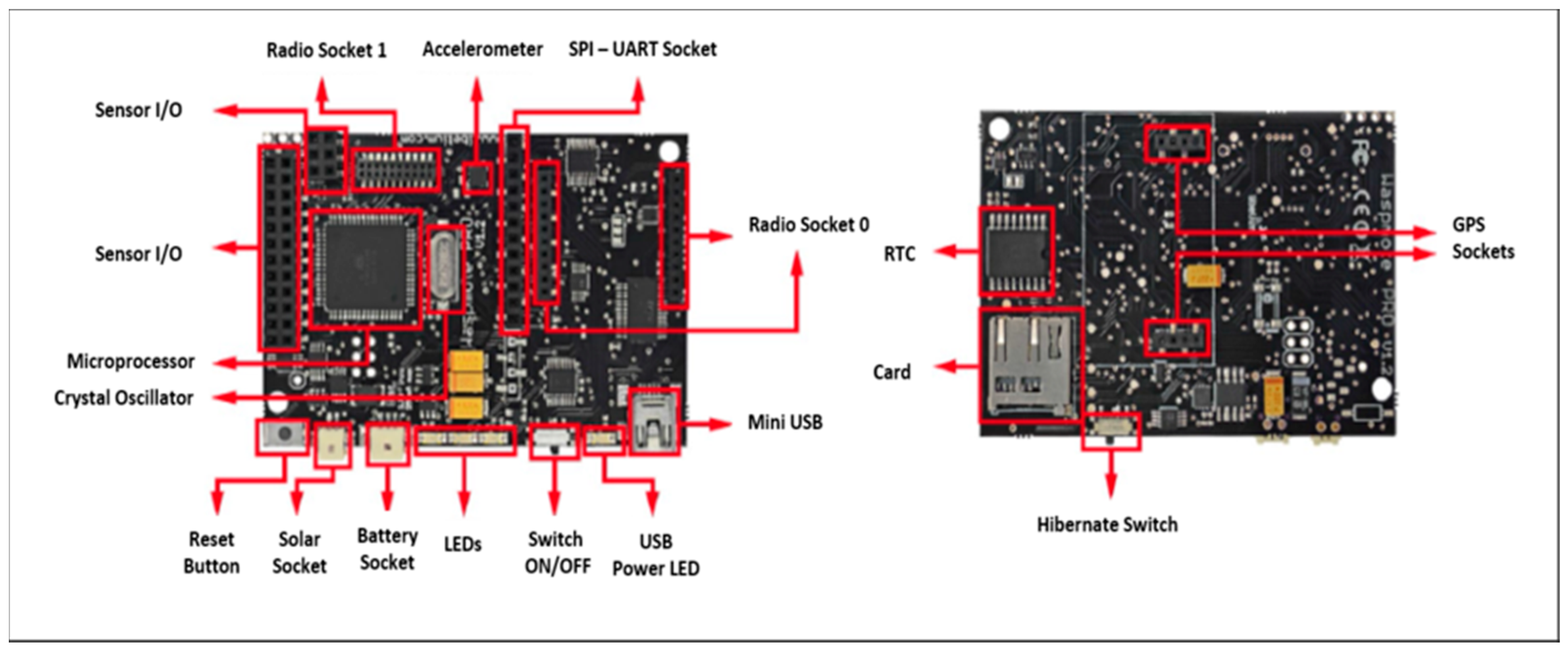
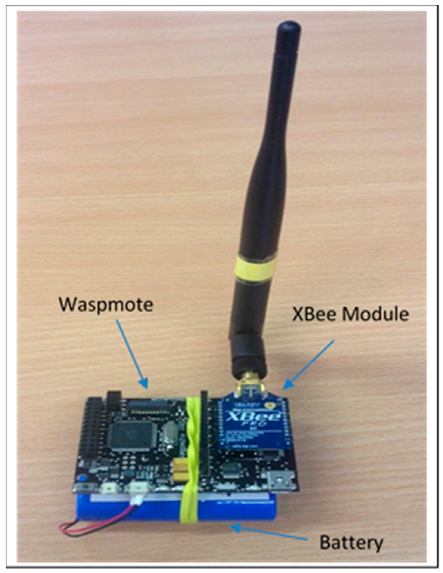
In this section, we present the implementation and test measurements of the scheme. The implementation involves four Waspmote nodes, a Waspmote Gateway, four XBee 802.15.4 Pro modules with antennae (Figure 8), a MC1322x USB ZigBee dongle, an Agilent 66321D Mobile communication DC Source, a Waspmote Pro IDE version 04 with Waspmote Pro API Version 013 software based on Arduino, X-CTU provided by Digi and the Wireshark network analyzer.
Below is an outline of the three scenarios used to provide measurements to obtain the optimum configuration. The three scenarios were:
(1)
Four nodes and the gateway at a distance of 80, 120 or 160 m between end points in line topology.
(2)
Three nodes and the gateway at a distance of 80, 120 or 160 m between end points in the line topology.
(3)
One repeater node between sender and the gateway at a distance of 80, 120 or 160 m between end points in the line topology.
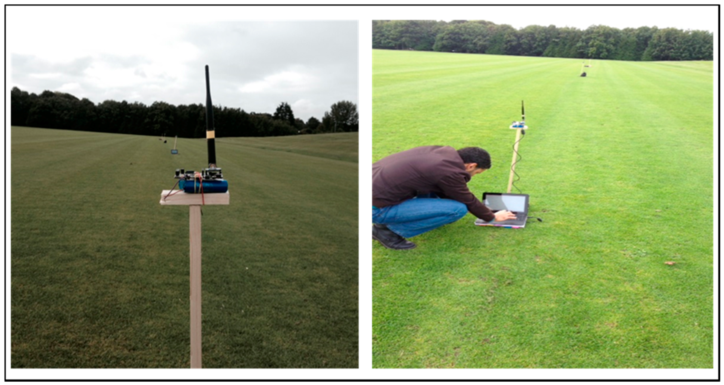
Figure 9 shows the physical setup of the scheme, where each Waspmote was placed on a fixed pole at a height of 80 cm from the ground. The effects of temperature and humidity on RSSI in WSNs as in [18] was considered. In this scenario the temperature was between 20 °C and 21 °C and the humidity was 70%.

4.1. Received Single Strength Indicator Measurement

In order to ascertain the received single strength indicator (RSSI) a test involving the transmission of a fixed amount of data was performed. In this experiment, the received single strength indicator (RSSI) was measured at the gateway. 
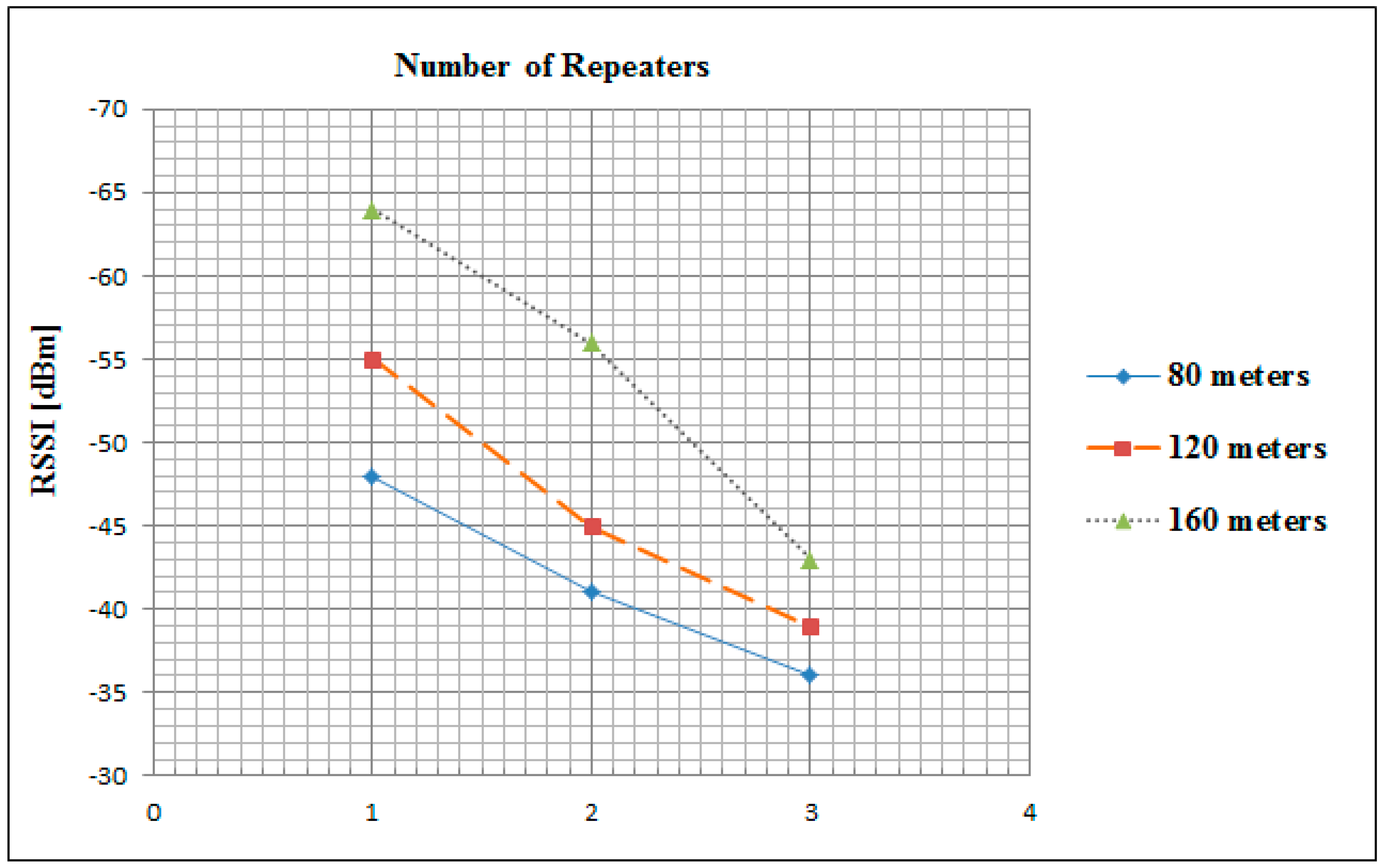
Figure 10 depicts the average value of RSSI which was measured after receiving 300 encrypted packets of 79 bytes in size at a baud rate of 115,200 bps.
These values were measured in the three aforementioned scenarios of distances and repeaters. The signal strength in the 80 m scenario was the strongest in the all case of one, two and three repeaters at exactly −48, −41 and −36 dB respectively. However, in the case of one repeater the 160 m scenario had the minimum signal strength value at −64 dB. While, in the case of all possible scenarios (as mentioned in Section 3) the maximum achievable signal strength is −36 dB, which is the 80 m distance with three repeaters scenario. These measurements are used by the leader node to determine the positions of future new joining nodes into the line topology.

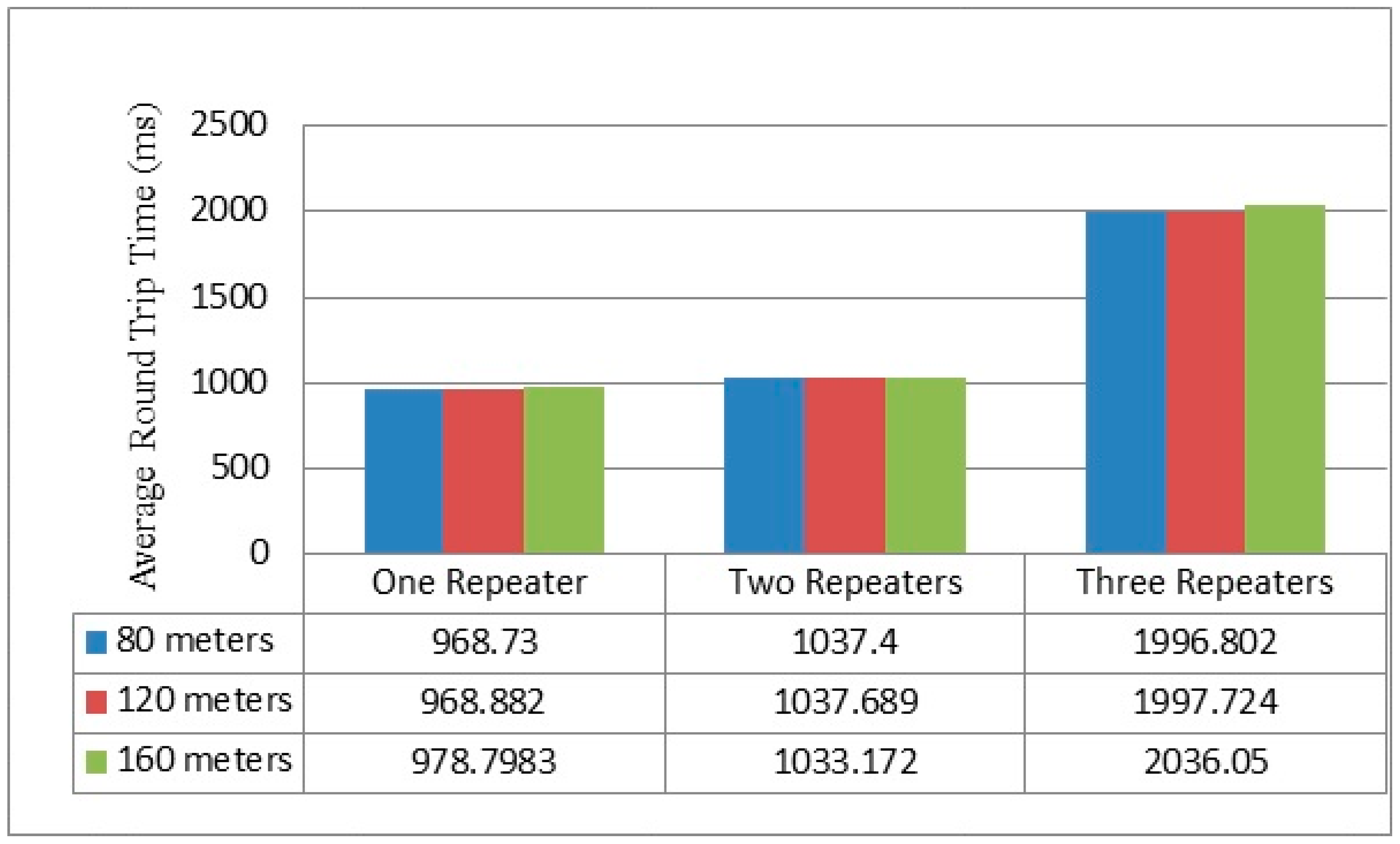
4.2. Round Time Trip Measurement

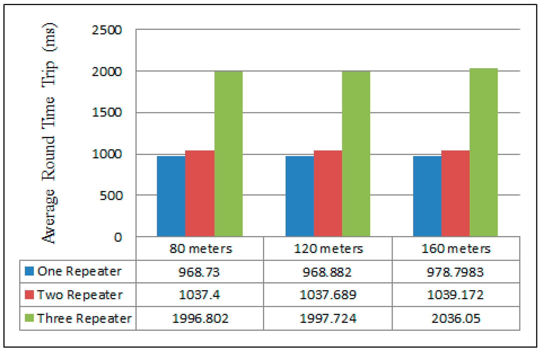
Figure 11 illustrates the average round time trip (RTT) for the different numbers of repeaters when increasing the distances between the sender and the gateway. In this experiment, RTT represents the elapsed time between the sender and the returned acknowledgment of the gateway to the last repeater. In fact, there was not a big difference in RTT measurements in the cases of one and two repeaters in all scenarios. However, in the three repeaters case, the time delay between 80 m and 160 m scenarios increased by approximately 39.248 ms, where RTT only increased by approximately 1.772 ms in the two repeaters case. The best RTT was obtained for the 80 m separation distance in all scenarios at 968.73, 1037.4 and 1996.802 ms in the one, two, and three repeater cases, respectively. These results were captured using a MC1322x USB Zigbee Dongle and the Wireshark network analyzer.

4.3. Current Consumption

Data processing relies on the size of the data and the approach used in processing this data. Furthermore, the designed scheme has been adapted to use minimum current consumption for data processing. 
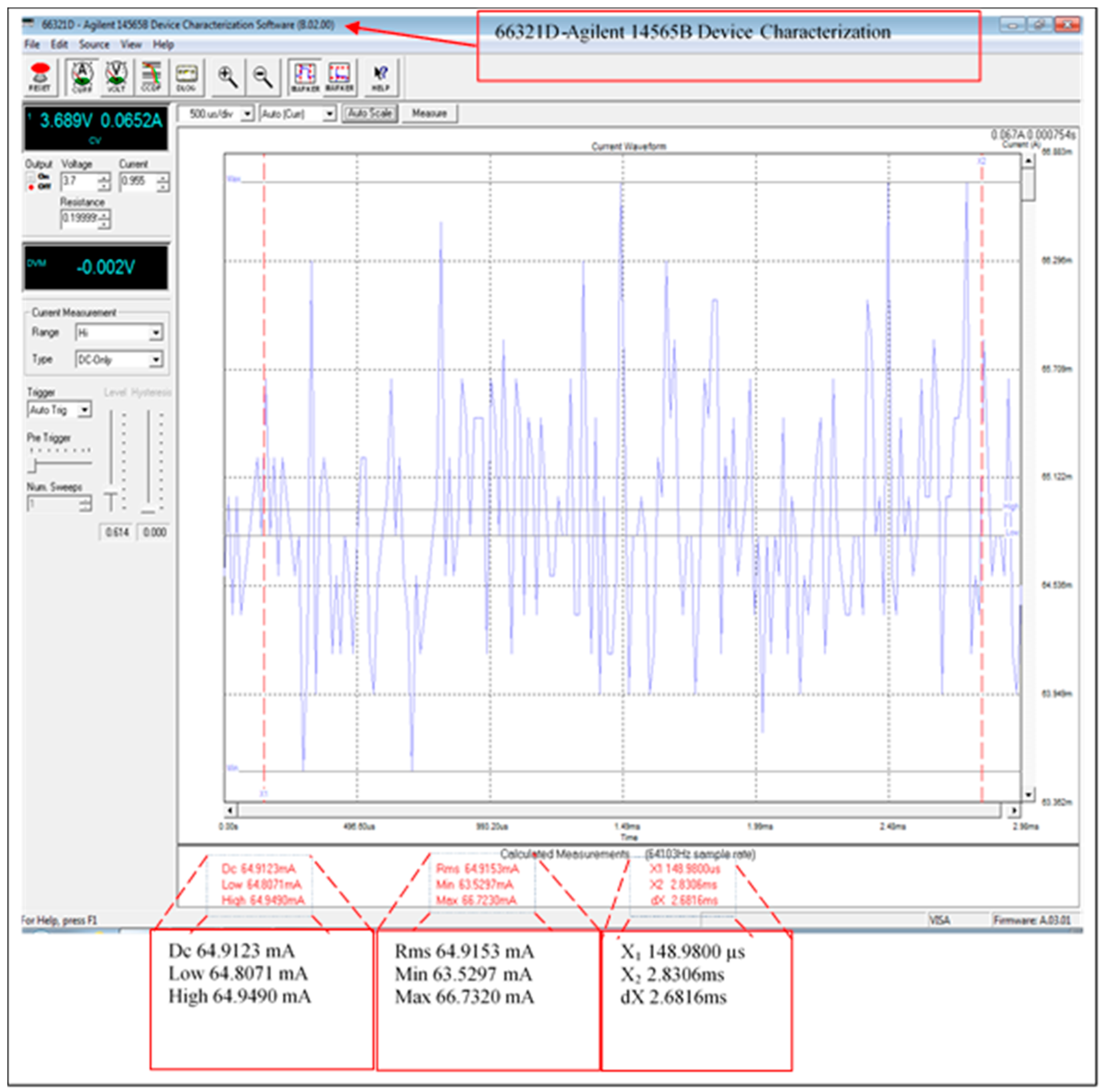
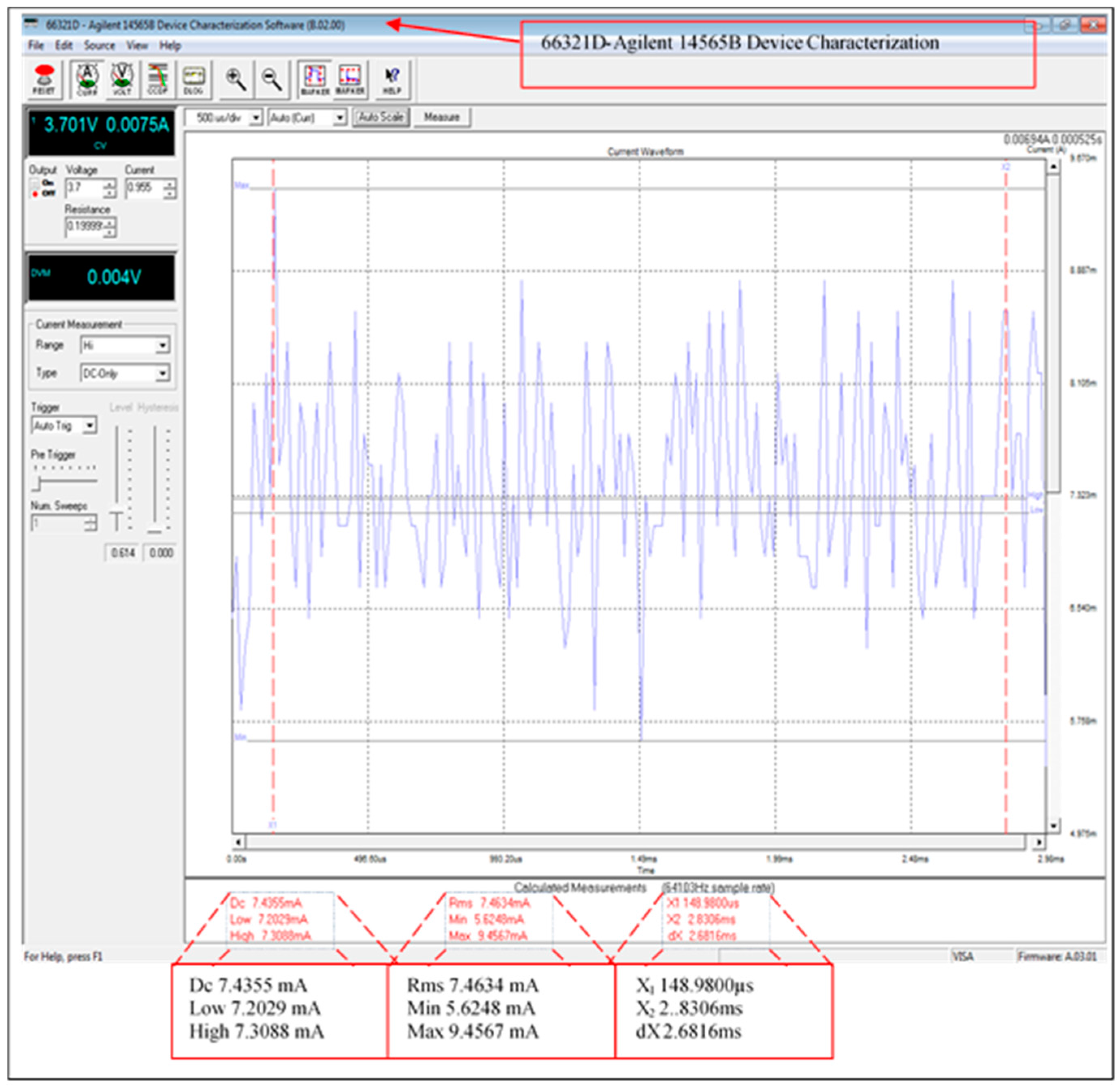
Figure 12 illustrates the average current consumption of the fully functional scheme including the XBee transmission module current consumption. However, the current consumption of the transmission data has been improved by using sleeping schedules for the receiving/transmitting modules (the XBee current consumption is from 37 to 64 mA with the mode ON fully operational). The measurements were taken using the 66321D-Agilent with input 3.689 V and 0.19999 Ω resistance. The average current consumption of the XBee module is 64.9123 mA when the leader node is fully operational, this was significantly improved by introducing the sleeping mode feature as described below.
The XBee module in the leader node will return to sleeping mode after transmitting/receiving data. Figure 13 shows the average current consumption of the sleeping mode of the XBee modules in the scheme. Where this is the total current consumption during data processing except for the transmission/receiving phase. The measured current consumption has been improved from 64.9123 to 7.4355 mA, which is a reduction of over 88%. Table 6 provides the current consumption of the scheme modes, this includes when the XBee module is fully functional and sleeping.

5. Discussion and Comparisons

In [
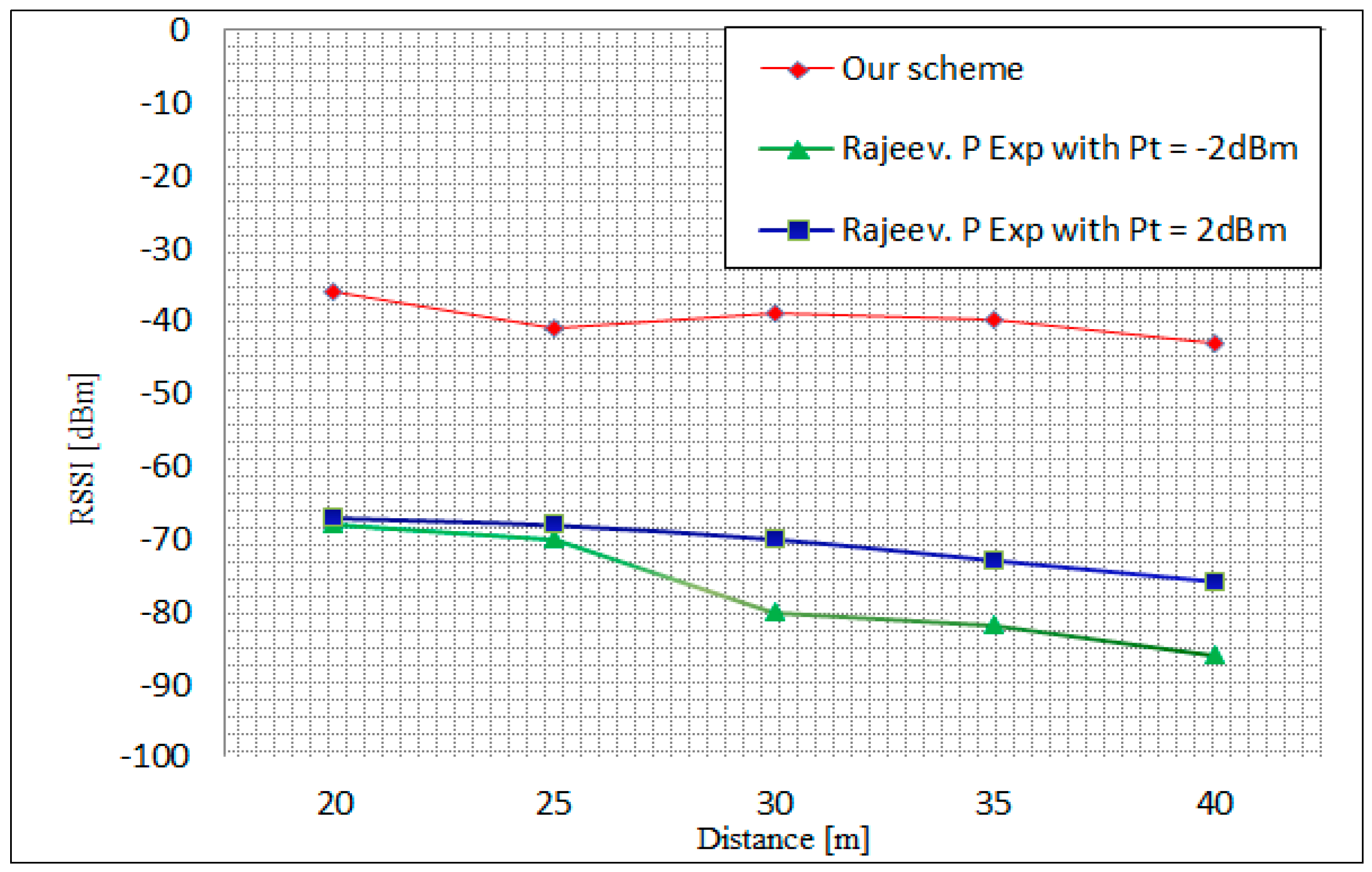
19] Piyare et al. evaluated the performance of ZigBee networks based on XBee modules in terms of RSSI. The experiment was based on the single-hop and multi-hop in line network topology. In this experiment, average values of the RSSI was measured after transmitting 50 packets of 30 Bytes with varied distance between the sender and the receiver. Figure 14 illustrates the relationship between the measured RSSI and the distance using two different transmit power values of −2 dBm and 2 dBm. In our scheme, the measurements have been taken after transmitting 300 encrypted packets of 97 Bytes in an outdoor environment. As shown in Figure 14, the three measured values of RSSI decreased when the distance between the sender and the receiver was increased. However, our scheme presents strong signal strength values at all distance scenarios, where the strongest value is −36 dBm at 20 m and the weakest value was −43 dBm at 40 m. In the 20 and 30 m distances, the fluctuation in this scheme is graphed and can be correlated with interference from other networks, e.g., reflection phenomena.
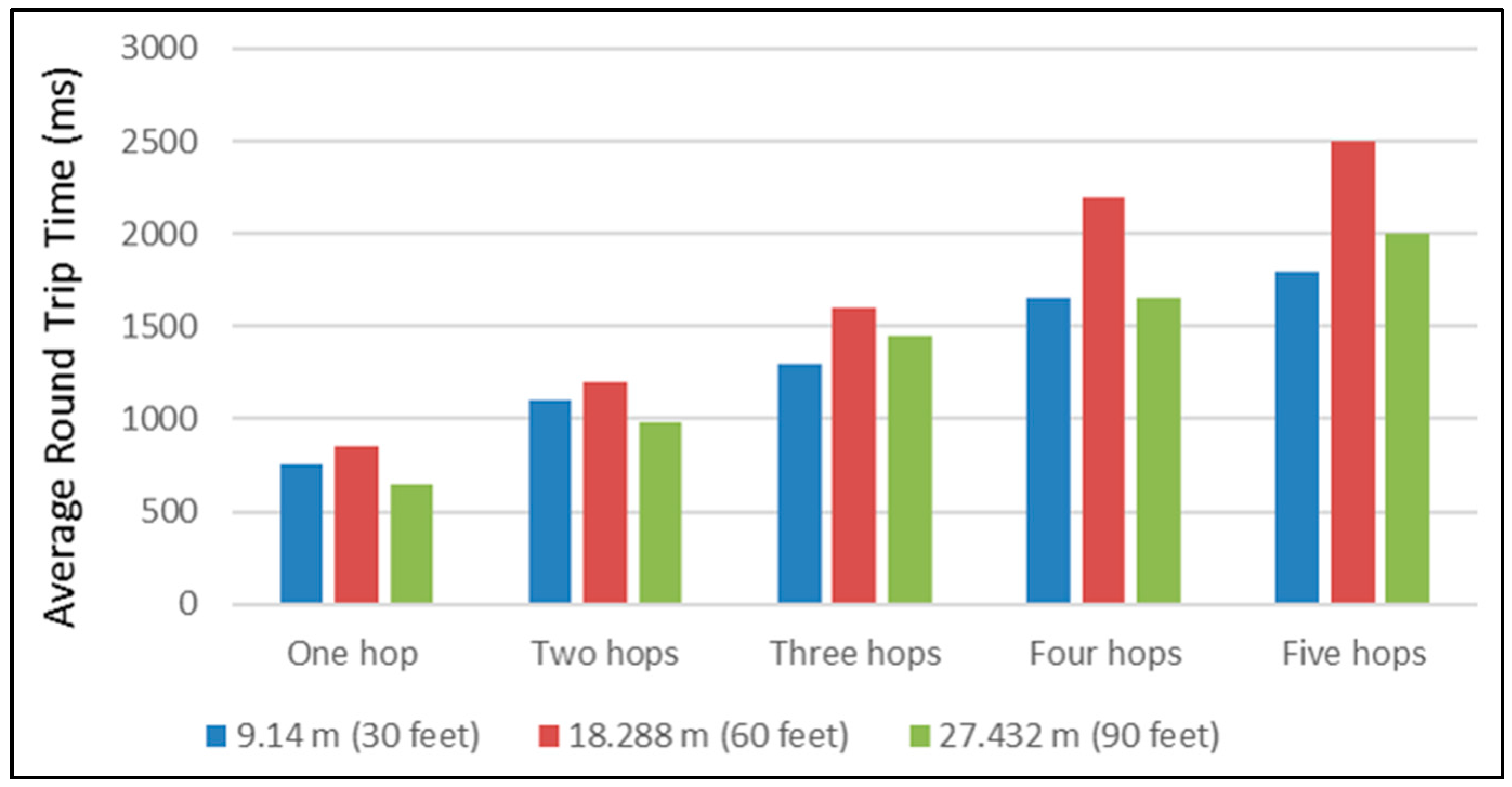
When comparing the work undertaken, it was compared to Jorg and Guangyu [12]. Figure 15 presents their result of the average Round Trip Time RTT of line network topology. The experimental setup consisted of multiple different scenarios of distance and number of repeaters. Initially, the scenarios were: 9.14 m (30 feet), 18.288 m (60 feet), and 27.432 m (90 feet) between nodes, with one hop, two hops, three hops, four hops, and five hop scenarios (one hop per repeater). Furthermore, Figure 16 depicts the three scenarios of our scheme, which are one repeater, two repeaters, and three repeaters in 80, 120 and 160 m distances between the sender and the gateway.
In the cases of 40 and 60 m distances between the nodes in the single repeater scenario, both schemes presented approximately the same time delay. However, in the two repeaters scenario, at a distance of 55 m the setup showed a time delay of 1033.172 ms and [12] presents approximately 1300 ms. In addition, the time delay between our scheme and [12] was around 170 ms in the same scenario at the distance of 27 m. Comparatively, travelling packets in the scheme being presented needed larger delays in comparison with [12] at distance of 40 m in the case of the three repeaters scenario. Generally, the time of receiving transmitting packets increase with the number of repeaters.
In Table 7 and Table 8, a comprehensive comparison between the scheme presented and three other schemes in terms of cryptographic scheme, size and number of stored security keys, memory space used by schemes, maintenance and re-keying strategy, scheme implementation environment, nodes and coordination, is shown.

6. Conclusions

This paper presents an analysis of the security performance of a WSN running a symmetric encryption security scheme that is suitable for use in a maritime coastal environment. The work made the re-keying process a local operation and minimized the use of key memory storage. The technique was implemented on the Waspmote platform and analyzed in terms of a received single strength indicator (RSSI), average round time trip (RTT), and current consumption. These measurements were taken in real time at the University of Limerick campus. The scheme implemented has improved some common security issues in WSNs, including:
  • Efficiency: 88.55% of current consumption was reduced using the XBee sleeping mode. This will improve the lifetime of all network sensor nodes.
  • Data confidentiality: by doubling the encryption of the messages, we ensure that only the gateway in the network can decrypt the original data (using AES 128) and after that, we establish Peer-to-Peer encryption between repeaters.
  • Authentication: each node has an individual key shared with the leader node, which is used to ‘sign’ the messages in order to ensure the authenticity of the new neighbor and the rekeying. This signing is performed when the leader node reconfigures the network topology in the case of joining or revoking network members.
  • Memory capacity storage: by using the re-generation function, there is no need for each node to store as many keys as are required in some key pre-distribution schemes where a large pool of keys is located in each node before deployment [20]. In our scheme, each node has only four keys. Therefore, every node requires only a small amount of memory for key storage, which is four times 128 bits.
  • Non-repudiation: by signing the XBee acknowledgment messages, there is now verifiable proof that the information sent has really been received by a specific sensor node. This signing using a shared source/destination key, Ks, provides weak non-repudiation as a public key scheme is not yet available in our system.
  • Forward security: in the reconfiguration of the scheme, new neighbors could not communicate directly before authentication process. The authentication process coordinates via a leader node.
  • Backward security: when a node is revoked from the network, the system ensures that the node cannot receive any new data from the network.
This work is progressing at our center and the current focus of the work is to facilitate the implementation of an efficient public key scheme for use in the protocol. The availability of an efficient public key scheme will enable the generation of digital signatures, provide strong non-repudiation and will further enhance key distribution for use in a line topology network [21,22,23,24].

Acknowledgments

This work was part supported by the SFI Centre for Marine Renewable Energy Ireland (MaREI). Grant References: 12/RC/2302 and 14/SP/2740.

Author Contributions

The proposed implementation was conceived and designed by Walid Elgenaidi, the main author of this article. Thomas Newe was the authors PhD supervisor and mentor. Eoin O’Connell as joint PhD supervisor contributed in the implementation and testing process. Daniel Toal is director of the MMRRC centre where this work was conducted with the assistance of Gerard Dooly, senior research fellow in the MMRRC.

Conflicts of Interest

The authors declare no conflict of interest.

References

  1. Mathur, A.; Newe, T.; Rao, M. Healthcare WSN: Cluster Elections and Selective Forwarding Defense. In Proceedings of the 9th IEEE International Conference on Next Generation Mobile Applications, Services and Technologies, Cambridge, UK, 9–11 September 2015; pp. 341–346.
  2. Elgenaidi, W.; Newe, T. Marine based Wireless Sensor Networks: Challenges and Requirements. In Proceedings of the 8th International Conference on Sensing Technology (ICST), Liverpool, UK, 1–4 September 2014.
  3. Gura, N.; Patel, A.; Wander, A.; Eberleand, H.; Shantz, S.C. Comparing Elliptic Curve Cryptography and RSA on 8-bit CPUs. In Proceedings of the Cryptographic Hardware and Embedded Systems (CHES), Cambridge, MA, USA, 11–13 August 2004; pp. 119–132.
  4. Perrig, A.; Szewczyk, R.; Wen, V.; Culler, D.; Tygar, J.D. SPINS: Security Protocols for Sensor Networks. Wirel. Netw. 2002, 8, 521–534. [Google Scholar] [CrossRef]
  5. Eschenauer, L.; Gligor, V. A key management scheme for distributed sensor networks. In Proceedings of the ACM Conference on Computer and Communication Security (CCS), Washington, DC, USA, 18–22 November 2002; pp. 41–47.
  6. Chan, A.P.H.; Song, D. Random key per-distribution schemes for sensor networks. In Proceedings of the 2003 Symposium on Security and Privacy, Berkeley, CA, USA, 11–14 May 2003; pp. 42–51.
  7. Kabara, J.; Calle, M. MAC Protocols Used by Wireless Sensor Networks and a General Method of Performance Evaluation. Int. J. Distrib. Sens. Netw. 2012, 2012, 834784. [Google Scholar] [CrossRef]
  8. Cuomo, F.; Della Luna, S.; Monaco, U.; Melodia, F. Routing in ZigBee: Benefits from Exploiting the IEEE 802.15.4 Association Tree. In Proceedings of the 2007 IEEE International Conference on Communications, Glasgow, UK, 24–28 June 2007; pp. 3271–3276.
  9. Wheeler, A. Commercial Applications of Wireless Sensor Networks Using ZigBee. IEEE Commun. Mag. 2007, 45, 70–77. [Google Scholar] [CrossRef]
  10. Raazi, S.M.K.R.; Lee, S. A survey on key management strategies for different applications of wireless sensor networks. J. Comput. Sci. Eng. 2010, 4, 23–51. [Google Scholar] [CrossRef]
  11. Liu, A.; Dong, M.; Ota, K.; Long, J. PHACK: An Efficient Scheme for Selective Forwarding Attack Detecting in WSNs. Sensors 2015, 15, 30942–30963. [Google Scholar] [CrossRef] [PubMed]
  12. Liebeherr, J.; Dong, G. An overlay approach to data security in ad-hoc networks. Ad Hoc Netw. 2006, 5, 1055–1072. [Google Scholar] [CrossRef]
  13. Wang, V.; Fang, S. A hierarchical key management scheme for secure group communications in mobile ad hoc networks. J. Syst. Softw. 2007, 80, 1667–1677. [Google Scholar] [CrossRef]
  14. Annadurai, P. Trust Based Hierarchical Key Management Scheme for Secure Group Communication in mobile Ad hoc networks. Int. J. Comput. Sci. Appl. 2008, 1, 974–1003. [Google Scholar]
  15. Jang, J.; Kwon, T.; Song, J. A Time-Based Key Management Protocol for Wireless Sensor Networks. In Information Security Practice and Experience; Springer: Heidelberg, Germany, 2007. [Google Scholar]
  16. Zhang, R.; Zhao, H.; Labrador, M.A. A Scalable and Energy Efficient Sink Location Service for Large-scale Wireless Sensor Networks. Ad Hoc Sens. Wirel. Netw. 2007, 4, 289–320. [Google Scholar]
  17. Luo, H.; Ye, F.; Cheng, J.; Lu, S.; Zhang, L. TTDD: A Two-tier Data Dissemination Model for Large-Scale Wireless Sensor Networks. J. Wirel. Sens. Netw. 2005, 11, 161–175. [Google Scholar] [CrossRef]
  18. Luomal, J.; Hakala, I. Effective of Temperature and Humidity on radio Signal strength in outdoor Wireless Sensor Network. In Proceedings of the Federated Conference on Computer Sceince and Information Systems, Lodz, Poland, 13–16 September 2015; pp. 1257–1265.
  19. Rajeev, P.; Seong, L. Performance Analysis of XBee ZB Module Based Wireless Sensor Networks. Int. J. Sci. Eng. 2013, 4, 1615–1621. [Google Scholar]
  20. Möller, S.; Newe, T.; Lochmann, S. Evaluation of Key Distribution Protocols for use with Wireless Sensor Networks. In Proceedings of the IEEE Sensors Applications Symposium (IEEE SAS 2009), New Orleans, LA, USA, 17–19 February 2009; pp. 25–28.
  21. Boyle, D.E.; Newe, T. On the implementation and evaluation of an elliptic curve based cryptosystem for Java enabled Wireless Sensor Networks. Sens. Actuators A Phys. 2009, 156, 394–405. [Google Scholar] [CrossRef]
  22. Cionca, V.; Newe, T.; Dãdârlat, V. Configuration Tool for a Wireless Sensor Network Integrated Security Framework. J. Net. Syst. Manag. 2012, 20, 417–452. [Google Scholar] [CrossRef]
  23. Möller, S.; Newe, T.; Lochmann, S. Prototype of a secure wireless patient monitoring system for the medical community. Sens. Actuators A Phys. 2012, 173, 55–65. [Google Scholar] [CrossRef]
  24. Healy, M.; Newe, T.; Lewis, E. Security for Wireless Sensor Networks: A Review. In Proceedings of the IEEE Sensors Applications Symposium (IEEE SAS 2009), New Orleans, LA, USA, 17–19 February 2009; pp. 80–85.
Figure 1. Nodes in line topology.
Sensors 16 02204 g001
Figure 2. Waspmote components, top and bottom sides.
Sensors 16 02204 g002
Figure 3. ASCII Frame structure.
Sensors 16 02204 g003
Figure 4. Format of the encrypted frame.
Sensors 16 02204 g004
Figure 5. Waspmote Frame on OSI stack for communication.
Sensors 16 02204 g005
Figure 6. Network reconnection process.
Sensors 16 02204 g006
Figure 7. Keys administration.
Sensors 16 02204 g007
Figure 8. Waspmote platform integrated with XBee-pro module.
Sensors 16 02204 g008
Figure 9. System outdoor deployment.
Sensors 16 02204 g009
Figure 10. Average RSSI in three different scenarios of outdoor implementation.
Sensors 16 02204 g010
Figure 11. Measurements of RTT in three different scenarios at three different distances.
Sensors 16 02204 g011
Figure 12. Fully operational average current consumption.
Sensors 16 02204 g012
Figure 13. Average current consumption of sleeping mode phase.
Sensors 16 02204 g013
Figure 14. Proposed scheme measured RSSI values with different distances versus the Piyare [19] results.
Sensors 16 02204 g014
Figure 15. Multi-hop measurement of average round trip time [12].
Sensors 16 02204 g015
Figure 16. Multi-repeaters round trip time measurement result.
Sensors 16 02204 g016
Table 1. Explanation of notation used in Figure 1.
SymbolDescription
ni, nj, nk, nlOrdinary nodes in the line topology
LnLeader node
{ }kSymmetric encryption/decryption with key k
MTransmitted sensor data
ksSecret encryption source key
kniSecret encryption adjacent key of node i
kiSecret encryption individual key of node i
kLnSecret encryption leader node key
{{M}ks}kniSensor data encrypted with source and adjacent keys
{M}kiMessage encrypted with individual key of node i
{M}kLnMessage encrypted with leader nod key
Table 2. Modules integrated in Waspmote.
ModuleProtocolFrequencyTx_PowerSensitivityRange
Xbee 802.14.5-pro802.14.52.4 GHz100 mW−100 dBm7000 m
XBee ZBee-ProZBee-Pro2.4 GHz50 mW−102 dBm7000 m
XBee 868RF868 HMz315 mW−112 dBm12 km
XBee 900RF900 MHz50 mW−100 dBm10 km
WiFi802.11b/g2.4 GHz0–12 dBm−83 dBm7000 m
GPRS-8500/900/1800/1900 MHz2W(Class 4) 859/900 MHz
1W(Class 1) 1800/1900 Mhz
−109 dBmkm typical carrier range
3G/GPRS-Tri-Band UMS 2100/1900/900 MHz
Quad-based GSM/EDGE, 850/900/1800/1900 MHz
−106 dBmkm typical carrier range
Bluetooth Low EnergyBluetooth v.4.0/Bluetooth Smart2.4 GHz −103 dBm100 m
Table 3. Maximum frame size per protocol.
ModuleMaximum Frame Size
XBee-802.15.4Link Encrypted@16bit Unicast98 Bytes
@64bit Unicast94 Bytes
Broadcast95 Bytes
Link Unencrypted100 Bytes
XBee-868100 Bytes
XBee-900Link Encrypted80 Bytes
Link Unencrypted100 Bytes
XBee-Digimesh73 Bytes
XBee-ZigBeeLink Encrypted@64bit Unicast66 Bytes
Broadcast84 Bytes
Link Unencrypted@64bit Unicast74 Bytes
Broadcast92 Bytes
Bluetooth-transparent connectionLimited by MAX_FRAME
GPRSLimited by MAX_FRAME
3GLimited by MAX_FRAME
LoRa/SX1272Limited by MAX_FRAME
WiFiLimited by MAX_FRAME
Table 4. AES-128 with ECB cipher mode and zeros padding.
AlgorithmKey SizeData Block SizeMode CipherPadding
AES-128128 bits16 BytesECBZEROS
Table 5. MD5 hash algorithm.
AlgorithmOutput Size (Bits)Internal State Size (Bits)Block Size (Bits)Max Message Size (Bits)Word Size (Bit)
MD5128128512264 − 132
Table 6. Measured current consumption of scheme modes.
Scheme ModeMeasured Current Consumption (mA)
Max Min Average
Fully functional system66.73263.529764.9123
XBee module (sleeping)9.45675.62487.4355
XBee module current consumption (awake) 57.275357.904957.4768
Table 7. Comparison between schemes.
SchemeOffline PhaseCryptographic SchemeKey Size (bits)Communication TypeNumber of Storage KeysMemory Space Used by the SchemeRe-Keying Strategy
Neighborhood Scheme [12]Certificate stored in each nodeHybrid (RSA and symmetric)128 Multicast/UnicastEach node stores: own public/private keys; own secret neighborhood key; neighbors secret key(s), and source key (used when the node is data source)Not GivenLocal operation, where each node updates keys with its current neighbor.
Hierarchical Key Management Scheme [13]No pre-loaded keysHybrid (D–H and Symmetric)Not GivenBroadcast (2-hop adjacent node)
  • Level 1 head stores its secret key and secret key of Level 2 head.
  • Level 2 head stores its secret key and secret key of Level 1 head.
  • Ordinary node stores the secret key of the Level 2 head, secret communication key, and DH keys.
Not GivenComplicated operation where each level head node must regenerate a number of keys.
Time-Based Key Management Scheme [15]Keys pre-loadedSymmetric64 Broadcast
  • 500 keys in center node.
  • 100 keys for sensor nodes (to ensure sharing of a key with at least one of 10 neighbors)
  • 4 KB for center node
  • 0.8 KB for sensor node
Only the nodes deployed at the same time when compromised node is revoked have to regenerate keys.
Presented SchemeKeys pre-loadedSymmetric AES-128 in ECB mode with zeros padding. Key generation -MD5 and RTC.128Unicast (5 keys) Each ordinary node stores; own adjacent key; neighbor shared adjacent key; an individual key that is shared with leader node; Leader node master key, and a source key (used when the node is data source).Program size 57,230 bytes Ram required 4987 bytes.Re-keying in this scheme is a local operation, where only one node must update its adjacent key, in addition to the leader node key.
Table 8. Comparison between schemes.
SchemeImplementation EnvironmentNode CoordinationComments
Neighborhood Scheme [12]
  • Simulation using the Glomosim Simulator.
  • Used HP iPAQ 550 PDAs outdoors.
  • Node authentication is performed without coordination with other nodes.
  • Provides protection against attacks to the routing protocol using X509, RSA and a sequence number.
  • Rekeying is a local operation between the nodes that share neighborhood keys with a revoked node.
  • Provides forward and backward security.
  • Does not rely on an online trusted third party.
Hierarchical Key Management Scheme [13]Simulation only
  • Level 1 head coordinates all Level 2 heads in its subgroup.
  • Level 2 head coordinates all ordinary heads in its subgroup.
  • Uses a spanning tree topology in ad hoc networks.
  • Provides the forward and backward security.
  • Latency issues during the authentication process and updating secret keys.
Time-Based Key Management Scheme [15]Simulation only
  • For additional node deployment a centre node coordinates the authentication.
  • The scheme is not suitable for a large sensor network because of key storage requirements.
  • Offers protection against wormhole and sinkhole attack.
  • Provides forward and backward security.
Presented Scheme
  • Waspmote nodes and Gateway, XBee 802.15.4 Pro module with antenna. MC1322x USB ZigBee dongle. Agilent 66321D Mobile DC Source.
  • Waspmote Pro IDE v04 with Pro API v013 software based on Arduino. X-CTU provided by Digi and the Wireshark network analyzer in an outdoor implementation.
  • The Leader node monitors the behaviour of all ordinary nodes in this scheme.
  • It is responsible for the authentication, revocation, and reconfiguration phases of other nodes.
  • Provides protection against attacks to the routing protocol using location based routing.
  • Node addition or revocation is handled by the Leader Node.
  • Rekeying is a local operation between the nodes that share neighborhood keys with a revoked node.
  • Provides forward and backward security.
  • Does not rely on online trusted third party.
  • All message exchanges are acknowledged.

