
Resonance-Based Reflector and Its Application in Unidirectional Antenna with Low-Profile and Broadband Characteristics for Wireless Applications


Abstract
:1. Introduction
2. Analysis and Design of RBR
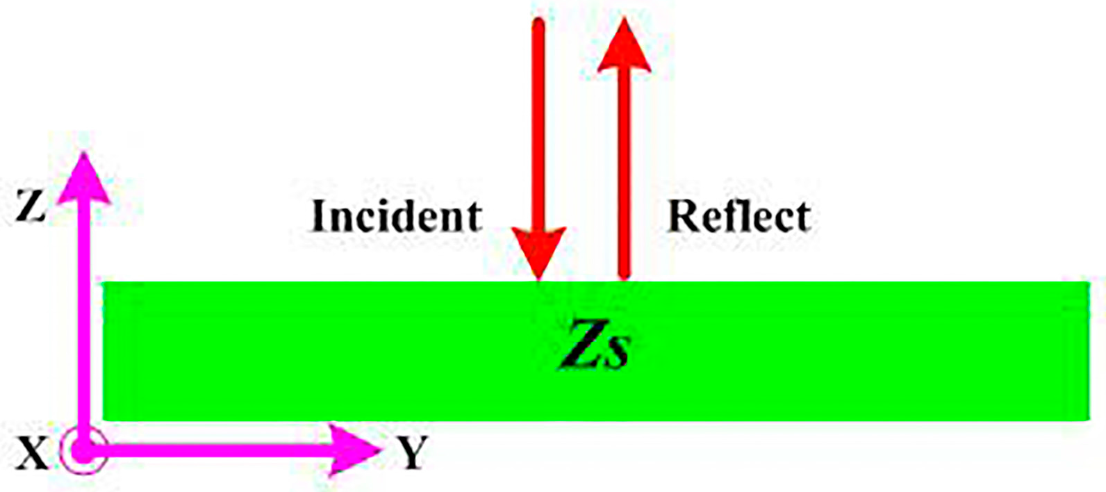
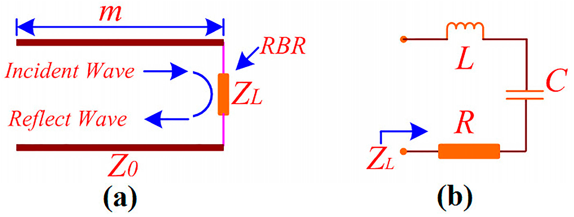
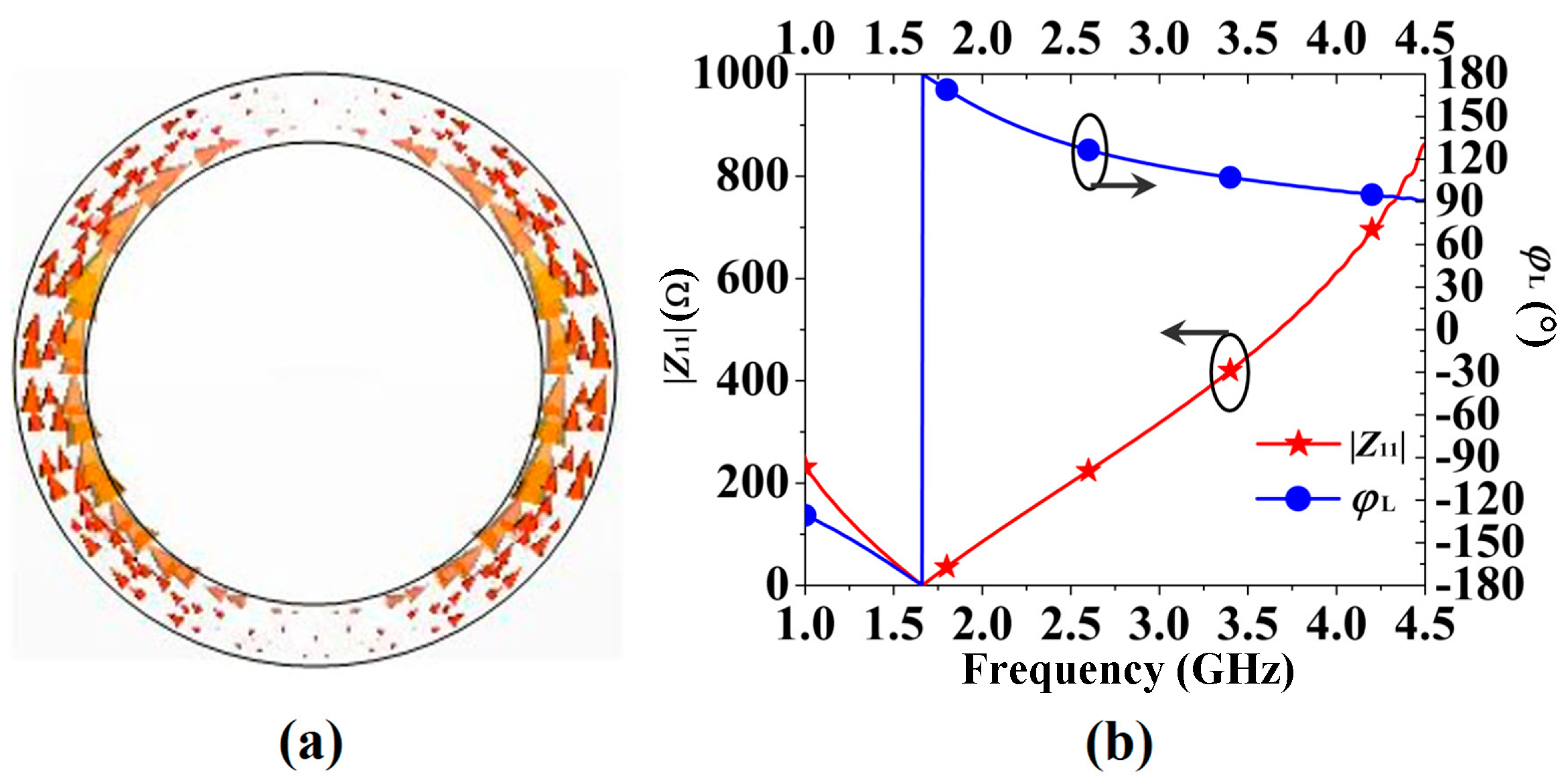
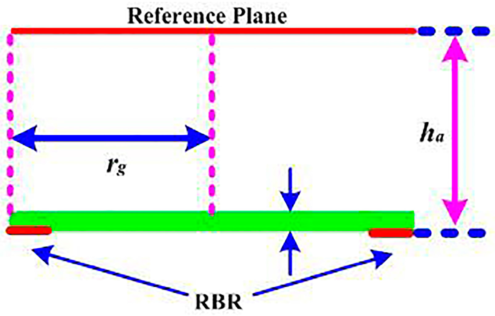
2.1. Theory Analysis of RBR
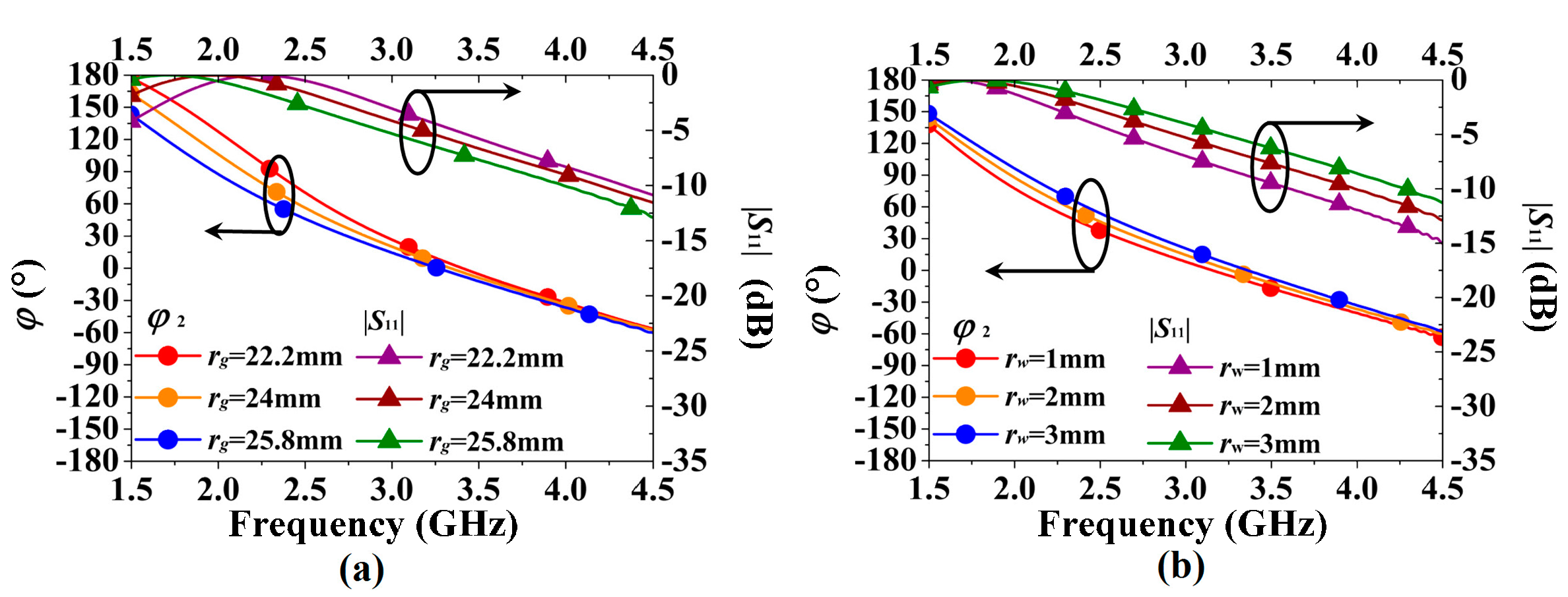
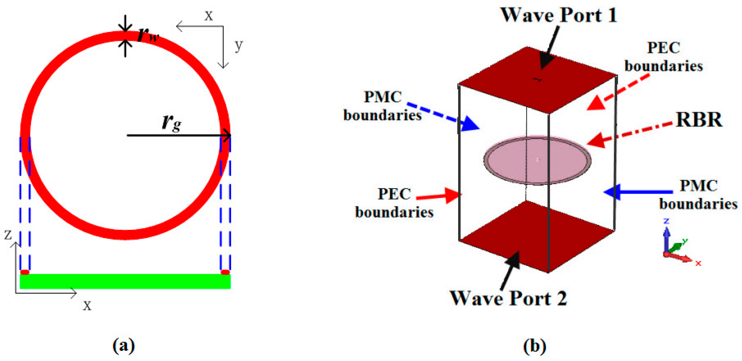
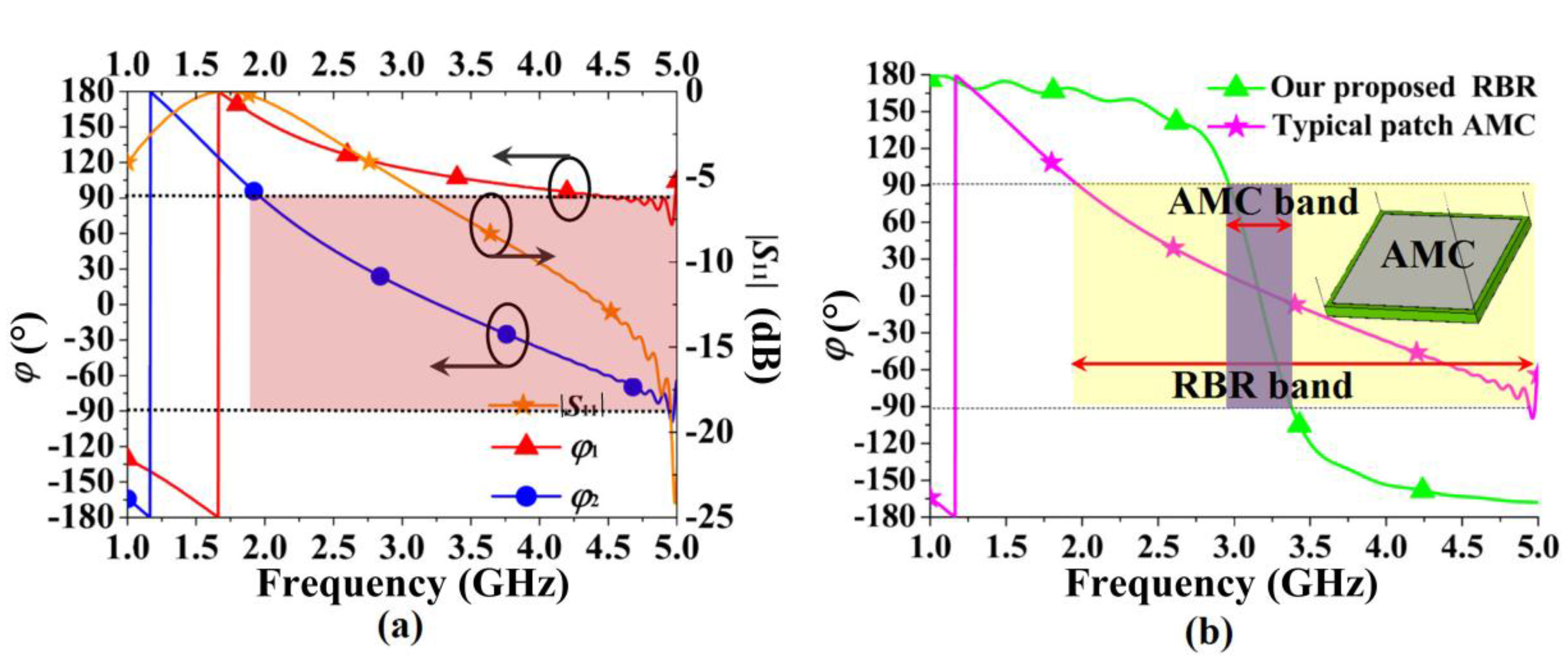
2.2. Design of RBR
3. Antenna Design and Discussion
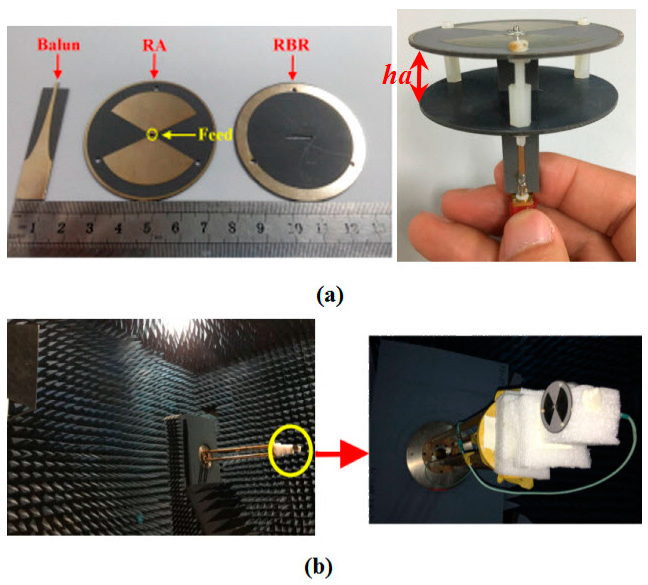
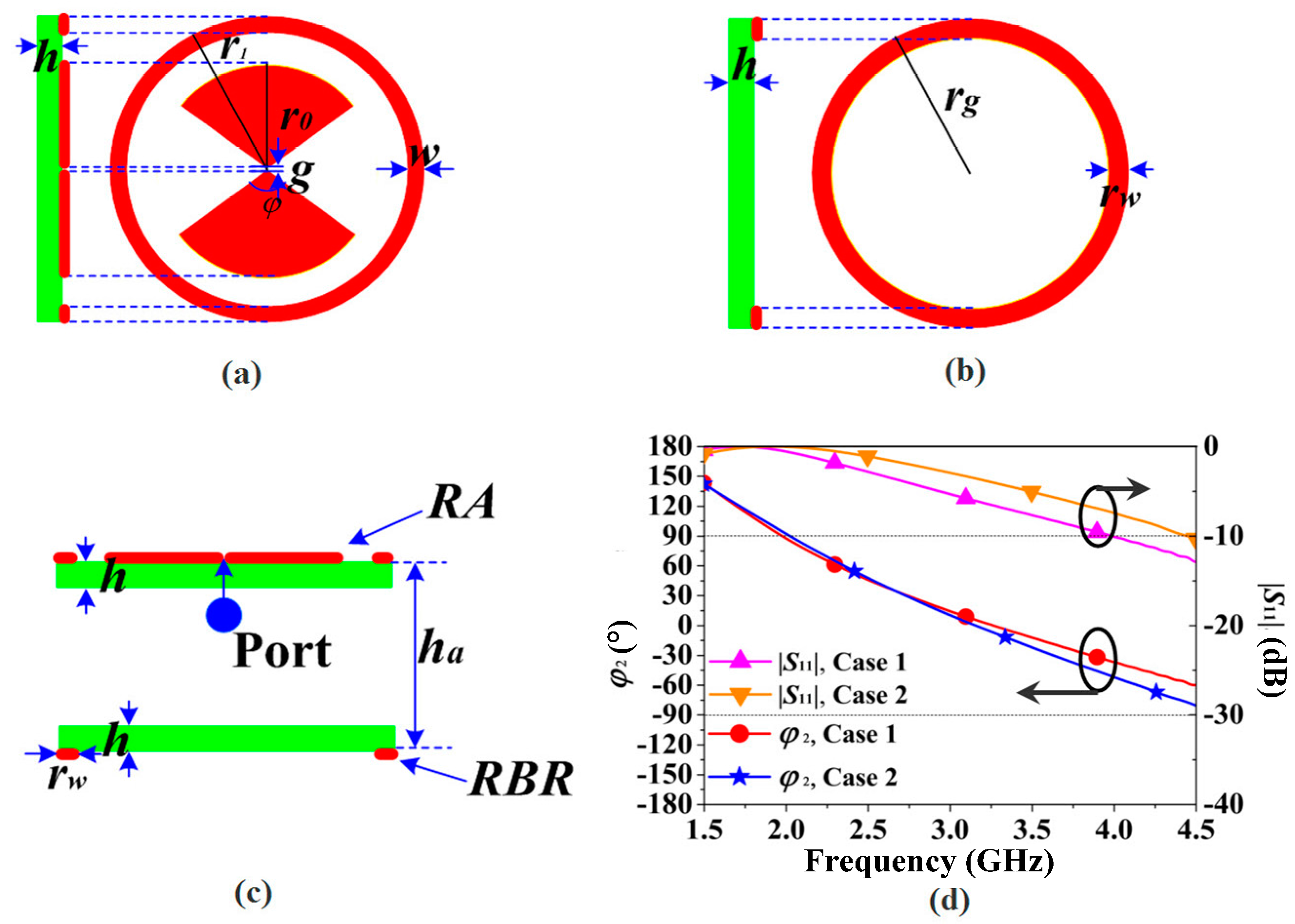
3.1. Antenna Design
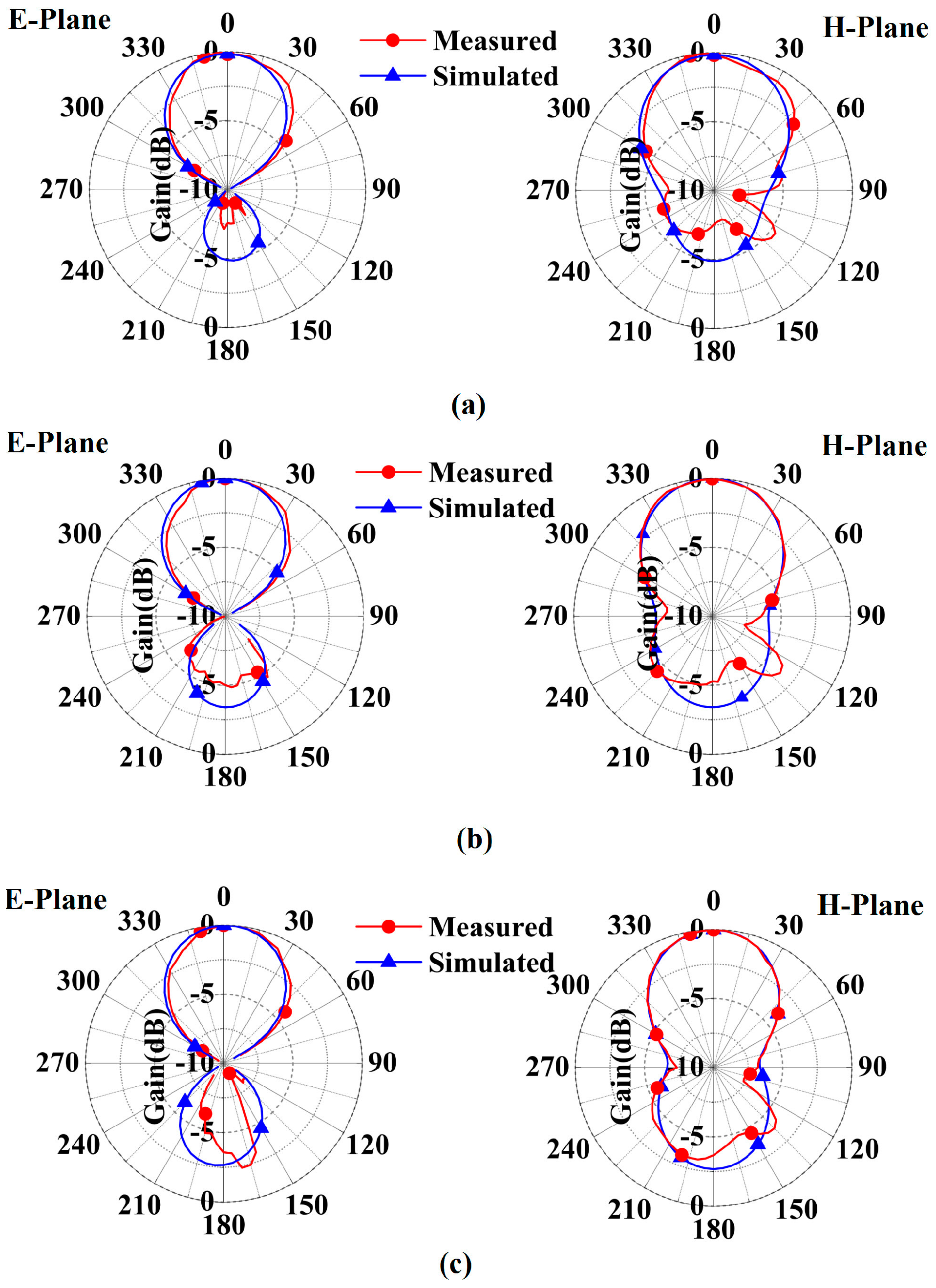
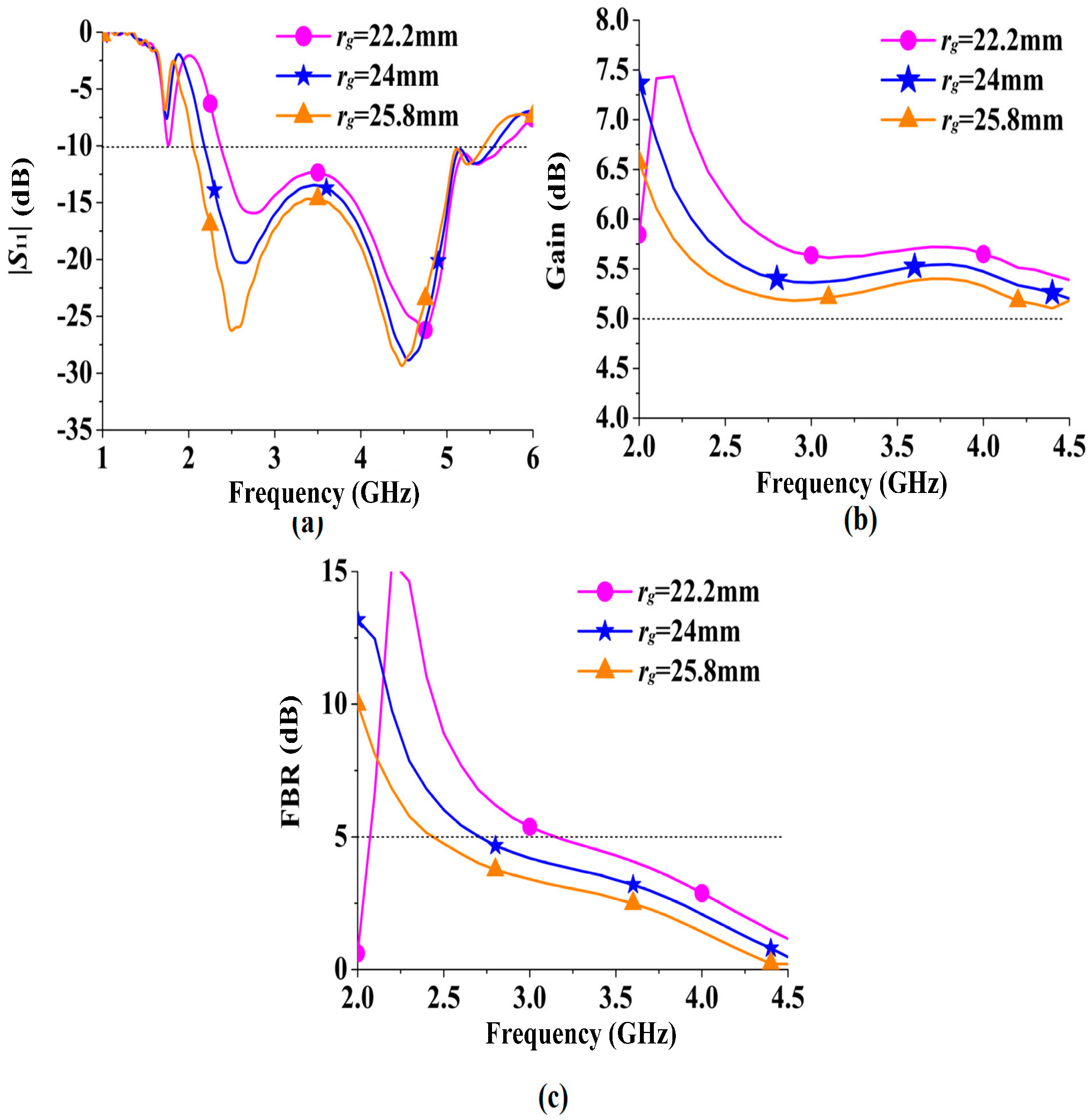
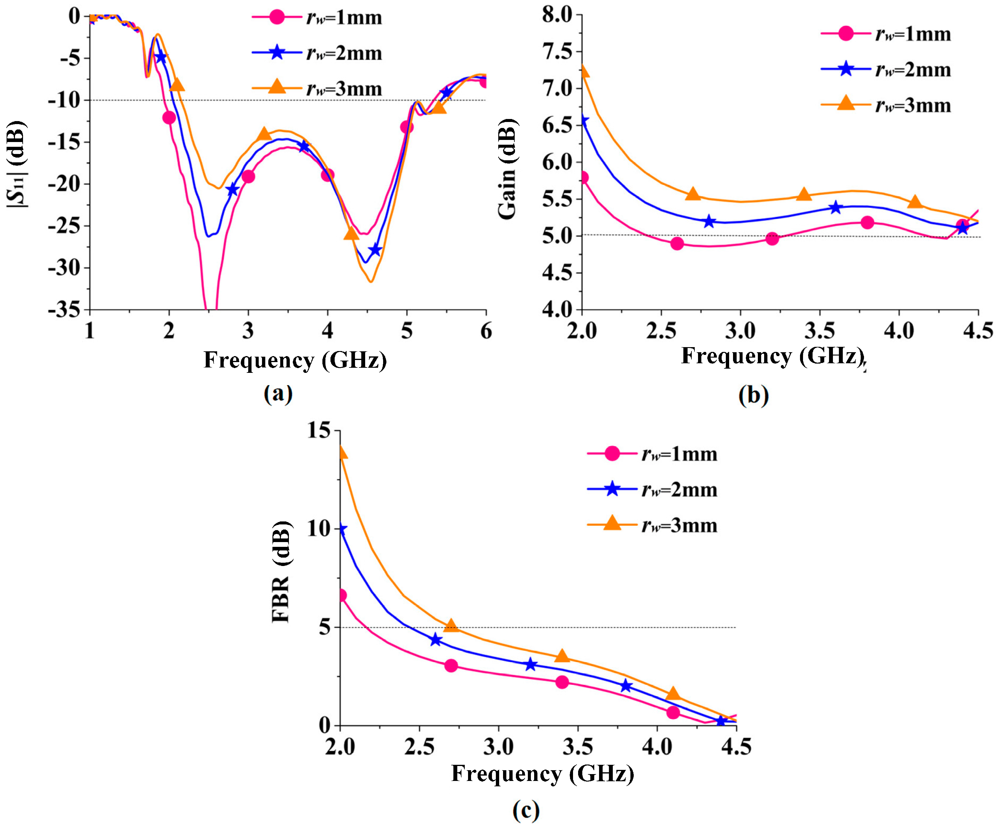
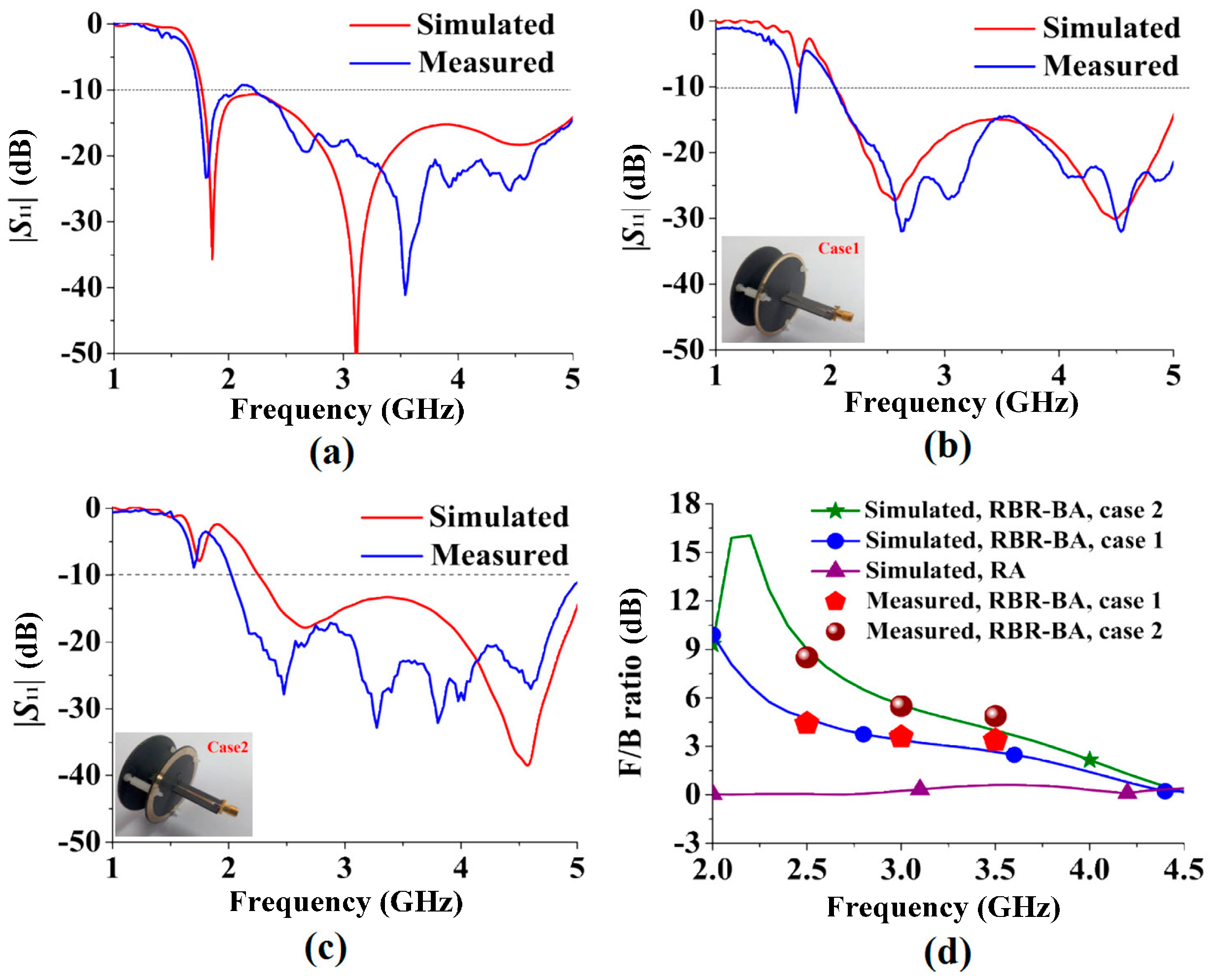
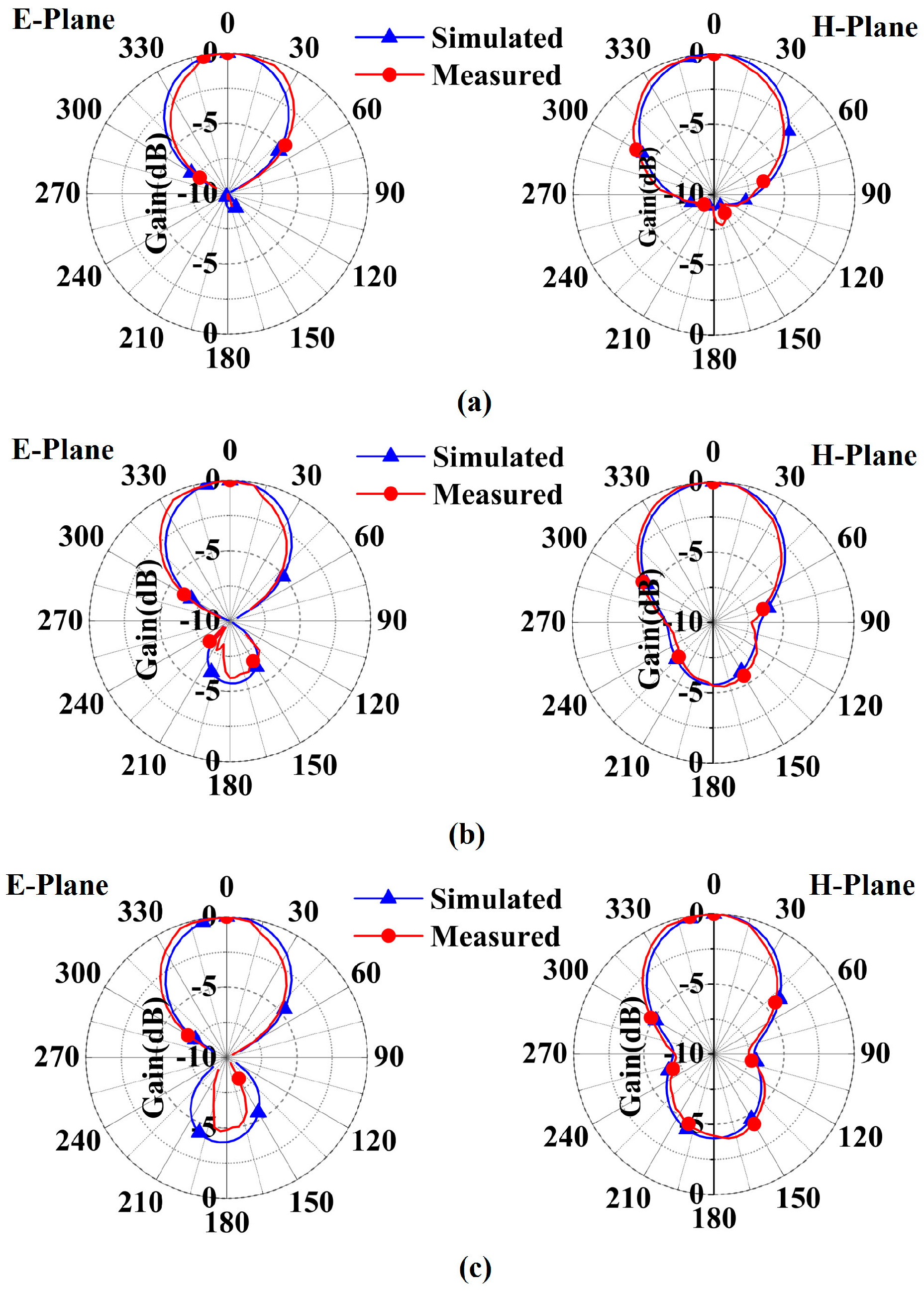
3.2. Discussion
4. Conclusions
Acknowledgments
Author Contributions
Conflicts of Interest
References
- Zivin, P.; Li, C.Z.; Lin, J.S. A broadband microstrip antenna with improved gain for noncontact vital sign radar detection. IEEE Antennas Wirel. Propag. Lett. 2009, 8, 939–942. [Google Scholar]
- Chen, Z.N.; Terence, S.P.S.; Qing, X.M. Small printed ultrawideband antenna with reduced ground plane effect. IEEE Trans. Antennas Propag. 2007, 55, 383–388. [Google Scholar] [CrossRef]
- Zhou, Z.S.; Boerner, W.M.; Motoyuki, S. Development of a ground-based polarimetric broadband SAR system for noninvasive ground-truth validation in vegetation monitoring. IEEE Trans. Geosci. Remote Sens. 2004, 42, 1803–1810. [Google Scholar] [CrossRef]
- Hwang, R.B. Broadband CPW-fed T-shaped antenna for wireless communications. IEE Proc. Microw. Antennas Propag. 2004, 151, 537–543. [Google Scholar] [CrossRef]
- Asimina, K.; Jorge, R.C.; Carlos, A.F.; Konstantina, S.N. A broadband implantable and a dual-band on-body repeater antenna: Design and transmission performance. IEEE Trans. Antennas Propag. 2014, 62, 2899–2908. [Google Scholar]
- Orlob, C.; Dao, Q.H.; Geck, B. Conformal Log-Periodic Antenna with Integrated Feeding Network for UWB-MIMO Applications. In Proceedings of the 7th German Microwave Conference, Ilmenau, Germany, 12–14 March 2012; pp. 1–4.
- Cai, Y.; Qian, Z.P.; Cao, W.Q. Compact wideband siw horn antenna fed by elevated-cpw structure. IEEE Trans. Antennas Propag. 2015, 63, 4551–4557. [Google Scholar] [CrossRef]
- He, S.H.; Shan, W. An improved vivaldi antenna for vehicular wireless communication systems. IEEE Antennas Wirel. Propag. Lett. 2014, 13, 1505–1508. [Google Scholar]
- Chen, Z.N. Wideband microstrip antennas with sandwich substrate. IET Microw. Antennas Propag. 2008, 2, 538–546. [Google Scholar]
- Peng, L.; Xie, J.Y.; Jiang, X.; Li, S.M. Wideband microstrip antenna loaded by elliptical rings. J. Electromag. Waves Appl. 2016, 30, 154–166. [Google Scholar] [CrossRef]
- Deshmukh, A.A.; Ray, K.P. Broadband proximity-fed square-ring microstrip antennas. IEEE Antennas Propag. Mag. 2014, 56, 89–107. [Google Scholar] [CrossRef]
- Markus, H.N.; John, L.V. Ultrawideband antennas for multiband satellite communications at UHF-Ku frequencies. IEEE Trans. Antennas Propag. 2015, 63, 1334–1341. [Google Scholar]
- Peng, L.; Xie, J.Y.; Jiang, X.; Li, S.M. Investigation on ring/split-ring loaded bow-tie antenna for compactness and notched-band. Frequenz 2016, 70, 89–99. [Google Scholar] [CrossRef]
- Omar, A.A. Design of ultrawideband coplanar waveguide-fed koch-fractal triangular antenna. Int. J. RF Microw. Comput. Eng. 2013, 23, 200–207. [Google Scholar] [CrossRef]
- Shingo, O.; Shuichi, M. An improvement in electrical charactertistics of a short backfire antenna. IEEE Trans. Antennas Propag. 1983, 31, 644–646. [Google Scholar]
- Adel, E.; Wu, J.F.; Kamal, S. Dual polarized wideband directional coupled sectorial loop antennas for radar and mobile base-station applications. IEEE Trans. Antennas Propag. 2015, 63, 1505–1513. [Google Scholar]
- Yang, F.; Yahya, R.S. Microstrip antennas integrated with electromagnetic band-gap (EBG) structures: A low mutual coupling design for array applications. IEEE Trans. Antennas Propag. 2003, 51, 2936–2946. [Google Scholar] [CrossRef]
- Jodie, M.B.; Magdy, F.I. A low-profile Archimedean spiral antenna using an EBG ground plane. IEEE Antennas Wirel. Propag. Lett. 2004, 20, 223–226. [Google Scholar]
- Mohammed, Z.A.; Mohammod, A. Novel wideband directional dipole antenna on a mushroom like EBG structure. IEEE Trans. Antennas Propag. 2008, 56, 1242–1250. [Google Scholar]
- Kim, E.Y.; Yoon, J.H.; Yoon, Y.J. Low profile dual-band reflector antenna with dual resonant AMC. IEEE Trans. Antennas Propag. 2011, 11, 1800–1803. [Google Scholar]
- Haider, R.R.; Ayman, I.A.; Hussain, M.A.; Daniel, G.R. Flexible and compact AMC based antenna for telemedicine applications. IEEE Trans. Antennas Propag. 2013, 61, 524–531. [Google Scholar]
- Rens, B.; Marta, M.V.; Jens, L.; Sybille, H.; Luca, S.D.; Peter, M. Low profile Galileo antenna using EBG technology. IEEE Trans. Antennas Propag. 2008, 56, 667–674. [Google Scholar]
- Zhong, Y.W.; Yang, G.M.; Zhong, L.R. Gain enhancement of bow-tie antenna using fractal wideband artificial magnetic conductor ground. Electron. Lett. 2015, 51, 315–317. [Google Scholar] [CrossRef]
- Sievenpiper, D.F. High-Impedance Electromagnetic Surfaces. Ph.D. Thesis, University of California, Los Angeles, CA, USA, 1999. [Google Scholar]
- Wang, X.W.; Li, Y.P.; Li, P. Microwave Technology and Antennas, 3rd ed.; Electronic Industry Publishing House: Beijing, China, 2012. (In Chinese) [Google Scholar]
- CST Microwave Studio. Available online: http/www.cst.com (accessed on 7 December 2016).
- Peng, L.; Sun, K.; Xie, J.Y.; Qiu, Y.J.; Jiang, X. UWB bi-directional bow-tie antenna loaded by rings. J. Korean Phys. Soc. 2016, 69, 22–30. [Google Scholar] [CrossRef]


| Para. | rg (mm) | rw (mm) | ha (mm) | |
|---|---|---|---|---|
| Ant. | ||||
| Case 1 | 25.8 | 2 | 14 | |
| Case 2 | 26 | 4.3 | 16.3 | |
© 2016 by the authors; licensee MDPI, Basel, Switzerland. This article is an open access article distributed under the terms and conditions of the Creative Commons Attribution (CC-BY) license (http://creativecommons.org/licenses/by/4.0/).
Share and Cite
Peng, L.; Xie, J.-y.; Sun, K.; Jiang, X.; Li, S.-m. Resonance-Based Reflector and Its Application in Unidirectional Antenna with Low-Profile and Broadband Characteristics for Wireless Applications. Sensors 2016, 16, 2092. https://doi.org/10.3390/s16122092
Peng L, Xie J-y, Sun K, Jiang X, Li S-m. Resonance-Based Reflector and Its Application in Unidirectional Antenna with Low-Profile and Broadband Characteristics for Wireless Applications. Sensors. 2016; 16(12):2092. https://doi.org/10.3390/s16122092
Chicago/Turabian StylePeng, Lin, Ji-yang Xie, Kai Sun, Xing Jiang, and Si-min Li. 2016. "Resonance-Based Reflector and Its Application in Unidirectional Antenna with Low-Profile and Broadband Characteristics for Wireless Applications" Sensors 16, no. 12: 2092. https://doi.org/10.3390/s16122092