
Forward Looking Radar Imaging by Truncated Singular Value Decomposition and Its Application for Adverse Weather Aircraft Landing

Abstract
: The forward looking radar imaging task is a practical and challenging problem for adverse weather aircraft landing industry. Deconvolution method can realize the forward looking imaging but it often leads to the noise amplification in the radar image. In this paper, a forward looking radar imaging based on deconvolution method is presented for adverse weather aircraft landing. We first present the theoretical background of forward looking radar imaging task and its application for aircraft landing. Then, we convert the forward looking radar imaging task into a corresponding deconvolution problem, which is solved in the framework of algebraic theory using truncated singular decomposition method. The key issue regarding the selecting of the truncated parameter is addressed using generalized cross validation approach. Simulation and experimental results demonstrate that the proposed method is effective in achieving angular resolution enhancement with suppressing the noise amplification in forward looking radar imaging.1. Introduction
The demand of civil aviation transportation in the all-time and all-weather has increased significantly since there is often the case that aircraft departure from one hub are delayed due to adverse weather, which results in many possible direct and indirect cost impacts. If there is known to be poor visibility at the destination region, the aircraft take off may be cancelled or delayed, disrupting the original flight schedule as well as impacting the scheduling of other planned flights [1]. Poor visibility is generally the result of fog, but other inclement weather conditions, such as rain, snow, sleet, dust storms or smoke, can also restrict visibility in the surrounding environment [2]. Several systems are designed to enhance situational awareness by providing supplemental visual data to the pilot, which includes runways, landing approach markers, other aircrafts and other terrain. These features could not be seen during night and low visibility conditions. There is a clear incentive consideration in providing sufficient visibility range or in generating a normal looking image in adverse weather using optical or radar sensor systems. Many of the achievements of aircraft landing problem have been accomplished to aid aircraft's takeoff and landing in adverse weather. A synthetic vision method for enhancing poor visibility flight operations can be found in [3], but the optical sensor generated imagery can not provide the sufficient visibility range in adverse weather. In [4], the authors developed a procedure for topographic terrain mapping, which is used for aircraft landing. Despite the progress in radar imaging methods, this method do not sufficiently detect slight angular changes of the targets in the image scene.
One of the most promising solutions to the problem is to use a forward looking scanning radar system that provides supplemental visual data to allow pilots to see through fog and other adverse weather, which has been widely used in many military and civilian fields, including remote sensing [5], flight navigation [6] and cargo airdropping [7], etc. The rationale behind the forward looking radar imaging is that utilizes the return power seen by the antenna beam to make image of the ground as the antenna beam scans the areas. To realize these applications, high resolution of the two dimensions for forward looking radar imagery is essential. The high range resolution can be achievable by transmitting the wideband signal and using the pulse compression technique. However, the angular resolution of forward looking scanning radar image is relatively poor when compared with the achievable range resolution. For forward looking scanning radar system, the angular resolution enhancement capabilities are physically limited by the effective wavelength and the physic size of antenna aperture. Therefore, the improvement in angular resolution of scanning radar image can be accomplished by either increasing the physical size of radar antenna, or by increasing the frequency of the transmitted signal. However, neither of these solutions were attractive. This demands use of signal processing techniques to process the acquired echo data and obtain improved angular resolution in scanning radar image. This kinds of techniques are called angular super-resolution algorithms in this paper. The main motivation behind the angular super-resolution lies in using mathematical processing methods to increase the angular resolution beyond the limitation of radar system parameters.
According to [8], the received signal g can be modeled by g = H * f + n, and our objective is to recover f from g, where * stands for the convolution operator, f is reflectivity of the scatter, n denotes noise, and H represents a convolution matrix acting on the f. Therefore, deconvolution method can enhance the angular resolution of a forward looking scanning radar imagery in theory [9,10]. Deconvolutiuon problem is physically considered as the analog of a linear inversion task, which is formulated and solved in [11]. Recently, applications of denconvolution can be found in [12–14] for imaging processing, [15–17] for microwave imaging, [18,19] for MRI and CT. Deconvolution method also has applications in radar imaging; see [20,21]. These deconvolution methods can be divided into two categories: classic and Bayesian approaches. Both classic (see [22–26]) and Bayesian (see [27–29]) approaches for solving the problem are posed as a minimization of a cost function having the general form
To address these challenges, the singular value decomposition (SVD) method is introduced. The conceptual intuition of the SVD facilities its increasing use in the theoretical analysis of deconvolution problem. For microwave imaging reconstruction, the SVD method is extensive used [31-34]. Truncated singular value decomposition (TSVD) is a popular method for solving the deconvolution problem. Recently applications of TSVD method can be found in [35] for inverse scattering problem, [11] for improving the spatial resolution of radiometer data, and [36] for image restoration. But little work on TSVD method for improving the angular resolution in forward looking radar imaging has been reported. This paper presents an angular superresolution algorithm that uses truncated singular value decomposition to solve the deconvolution problem corresponding to the scanning radar imaging task.
In this paper, we present an angular super-resolution method for adverse weather aircraft landing using the truncated singular value decomposition method, which is originally developed for solving the deconvolution problem with suppressing the noise amplification in the solution [37]. To this end, we first convert the angular super-resolution problem in forward looking radar imaging task into the corresponding deconvolution problem. It is well known that the deconvolution problem is ill-posed, which means the solution to the deconvolution problem is unstable and sensitive to the noise. To address this challenge, the truncated singular value decomposition method is used to solve the deconvolution problem, which is able to realize the angular super-resolution imaging in forward looking imaging for adverse weather aircraft landing. The rational behind the noise amplification is that the large errors in the solution come from the noise singular value decomposition components associated with the small singular of the convolution matrix. This leads to a compromise between these two factors must be considered. Fortunately, the TSVD method is able to chop off those SVD components that are dominated by noise. A key issue of TSVD method is the choice of the truncation parameter. This issue is beyond the scope of this paper and the method of selecting this parameter is provided by the generalized cross-validation criterion [37,38]. Simulations and experimental results are given to demonstrate the validity of the presented method for angular super-resolution imaging in forward looking scanning imaging, which can be used for adverse weather aircraft landing.
The remainder of this paper is organized as follows: In Section 2, we provide a theoretical background of angular super-resolution imaging in forward looking scanning radar imaging for aircraft landing. In Section 3, the truncated singular value decomposition for angular super-resolution imaging in forward looking scanning radar and the generalized cross-validation method for choosing truncated parameter are presented. Section 4 is dedicated to simulation and experimental results. Finally, in Section 5, we draw our conclusion.
2. Theoretical Background
In this paper, we focus our attention to angular resolution enhancement in forward looking scanning radar image for adverse weather aircraft landing by solving the corresponding deconvolution problem using truncated singular value decomposition method. To this end, we first formulate the signal model of forward looking scanning radar imaging, which is also a foundation of the application of the angular super-resolution method for adverse weather aircraft landing.
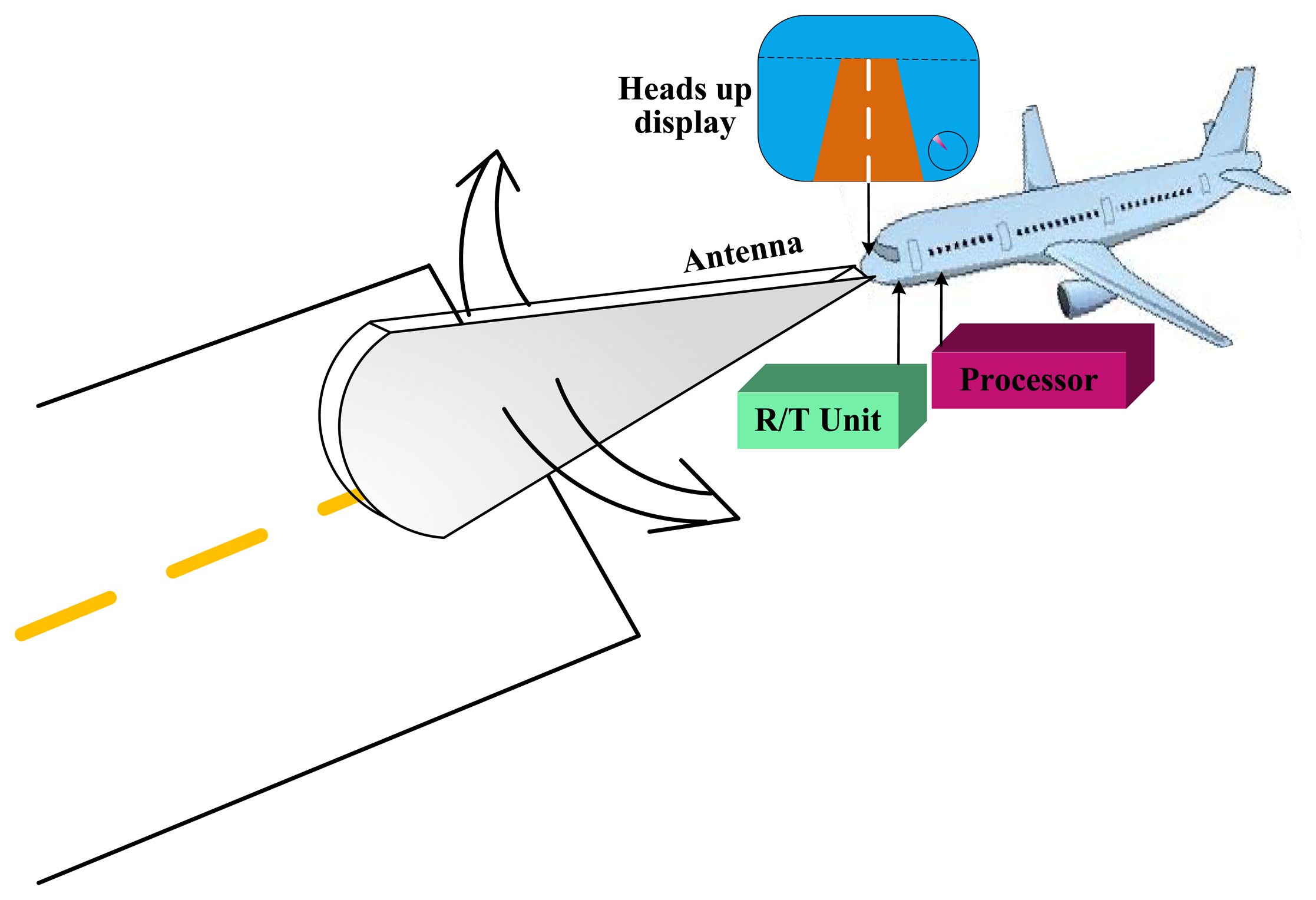
As shown in Figure 1, the forward looking scanning radar system consists of an antenna, radar receiver and transmitter (R/T) display processor and heads up display. The radar platform is moving along a runway corresponding to range direction, while the antenna scans along the vertical direction of runway corresponding to azimuth/angular direction with a constant angular velocity ω.
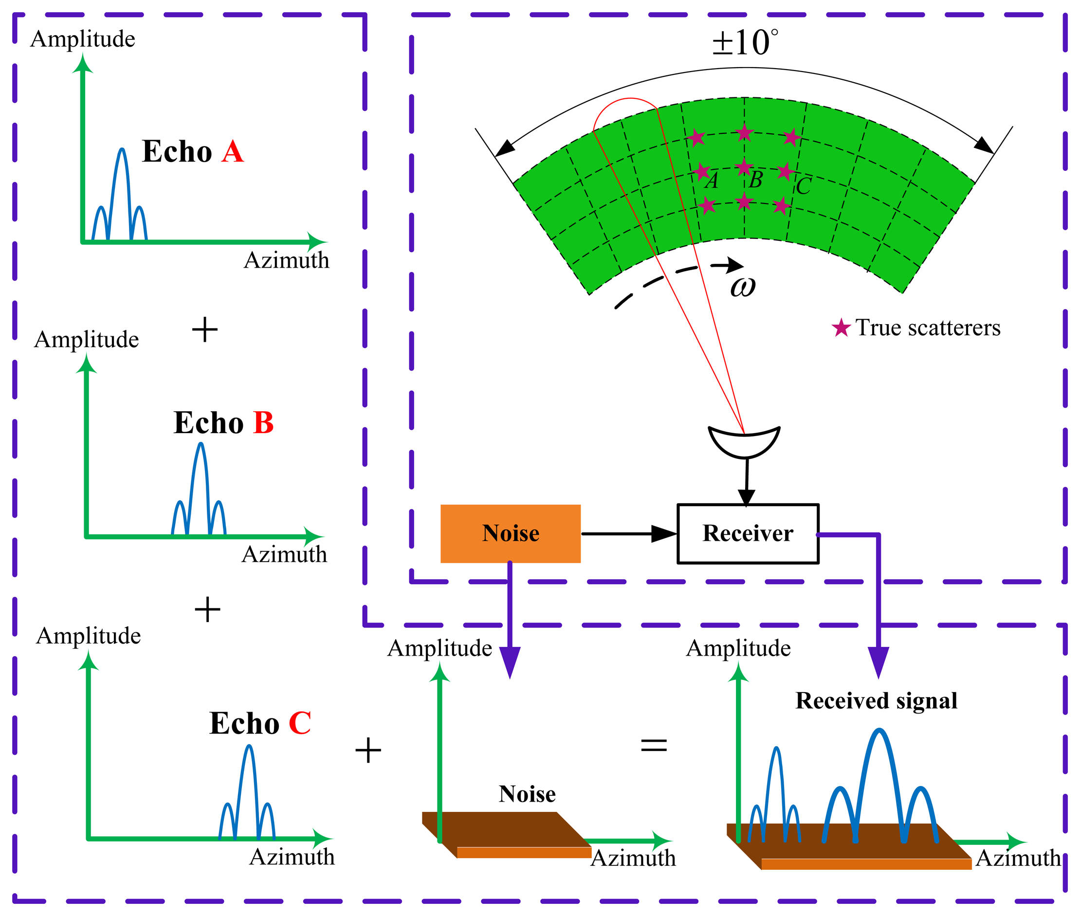
The diagram of the signal model of the forward looking scanning radar is illustrated in the upper-right of Figure 2. This is a top down view of the antenna scan pattern and the targets located at the same range cell with different azimuth cells. Assuming that the target in the observed scene can be considered as an ideal point target. The antenna scans the targets with a constant angular velocity ω and then receives the echo data from the observed scene. As the antenna beam scans a point target located at a particular angular, the received output is the impulse response of the corresponding to antenna pattern. We can see from the bottom of Figure 2 that when the target B and C are close enough, the echo of these two targets are proportional to two replicas of the antenna pattern, overlapped and added to get a composite response. The resulting low resolution signal is shown in the lower right corner of Figure 2.
According to [8], the limitation of angular resolution is determined by beam width of the antenna pattern. This phenomenon brings a great difficulty in realizing the angular super-resolution imaging in forward looking scanning radar. Our primal aim in this work is to process the acquired echo data and obtain improved angular resolution via signal processing technique that breaks through the physical limitation of radar system. To reach this goal, we first introduce the signal model of the scanning radar, which is the foundation of the following discussion.
At first, the conventional range compression and range migration correction are applied to the echo data with current approaches [20,39]. The echo data after range compression and range cell migration is denoted by g(θ, φ, r) where r denotes the slant range from the radar to the target and θ represents the angle between the direction of the antenna to the target and the flight direction, and φ stands for the incident angle of the antenna beam. On the other hand, it is assumed that the antenna pattern is of relative isotropy to the imaging scene. Then, the received signal of forward looking radar along the range profile can be assumed as a convolution kernel comprising the antenna power pattern in the angular coordinates and the pulse modulation function in the range direction, which could be expressed as
For mathematical simplicity, we only consider the azimuth variation. In addition, the presence of the noise makes the data g(θ) contaminated. According to [40], the echo data g (θ) can be modeled as a convolution of the antenna beam h (θ) with the reflectivity of the observed scene f (θ) plus the noise n(θ). Then, we can rewrite Equation (2) as
From Equation (3), we have
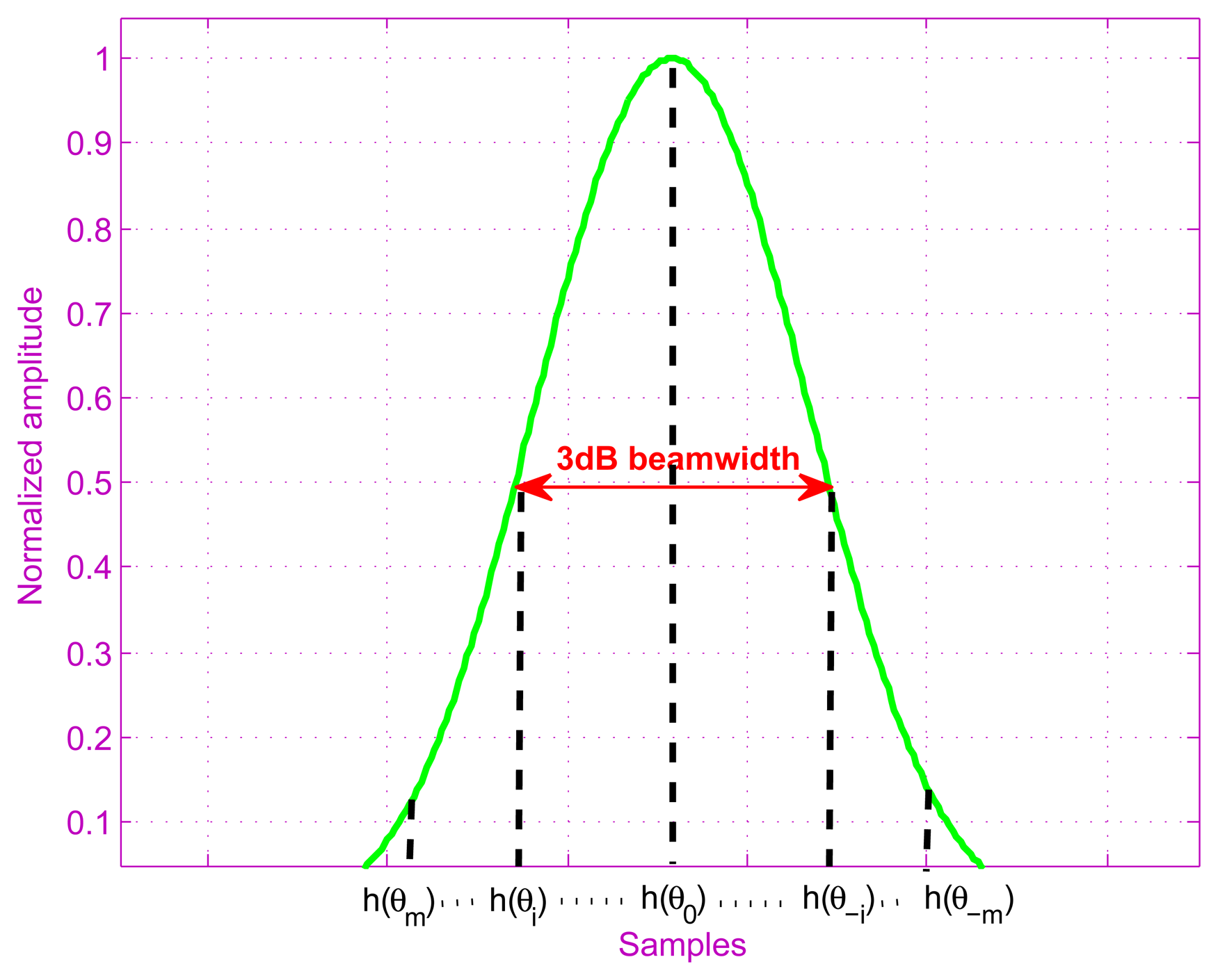
The superscript T in Equation (6) is used for the matrix-vector transposition. The sequence h(θm) ⋯ h(θ0) ⋯ h(θ−m) is a sampling of the antenna pattern, which is shown in Figure 3.
The forward looking scanning radar imaging for aircraft landing task is to recover [f (θ1), ⋯ , f (θk)]T given the convolution matrix H and the echo data g = [g(θ1), ⋯ ,g(θk)] of finite length. However, the echo data g is determined not only by [f(θ1), ⋯ , f(θk)]T, but also by Equation (6) and the system Equation (4) is underdetermined. To overcome this problem, some prior information about the observed scene should be incorporated. According to [41], we should make the assumptions on the values of the [f(θ1), ⋯ , f(θk)]T outside the domain where g is determined. In this paper, we assume that the true scene outside the field of view is a mirror reflection of the scene within the field of observation. This leads to that the convolution matrix is a Toeplitz-plus-Hankel matrix. More precisely, the convolution matrix H in Equation (4) can be written as follows:
For an area target scene, the reflectivity coefficients of the scatterers can be denoted as a 2-D matrix
Based on Equations (5), (6), and (7), the discrete expression of the echo data of the observed scene F can be expressed as follows:
Hence, the projection to obtain echo data from the observed scene is completed.
The angular super-resolution problem in forward looking radar can be converted that gives H, recovering f from g by solving the Equation (2). It notes that the angular super-resolution problem in forward looking radar can be physically considered as the analog of the antenna pattern H deconvolution. This problem is often called inverse problem, which is characterized by an ill-posed under-determined convolution matrix H. However, for the purpose of solving the deconvolution problem Equation (2) and consequently better angular resolution than that of the real antenna, the linear deconvolution can be stated as the task of finding a linear operator K = H−1 such that
3. Truncated Singular Value Decomposition for Angular Super-Resolution
In this section, we present the truncated singular value decomposition method to realize the angular super-resolution in forward looking scanning radar imaging. To this end, we first give the details of the singular value decomposition (SVD) as a foundation of the proposed method. Then, a truncated singular value decomposition method is presented for solving the problem Equation (2) and consequently create better angular resolution in radar image than that of real beam radar image.
The use of SVD goes back to Varah [42] and the early history of SVD is described in [43]. For mathematical simplicity, considering the matrix H in Equation (4), the SVD is given by
The solution of Equation (4) can be expressed as follows:
In this paper, the generalized cross-validation (GCV) method is adopted. An advantage of GCV is that does not require prior knowledge of the variance of the noise in the model Equation (4). The GCV is described in [44,45], which has proved to be an excellent method of choosing a regularization parameter. The GCV method aims at minimizing the predictive mean-square errors as follows:
4. Simulations and Experimental Results
In this section, we focus on the angular super-resolution performance of the TSVD method. Our purpose is to demonstrate the accuracy of the TSVD method. The accuracy of TSVD method is shown mainly by comparison with the angular super-resolution method in [20]. In the following, we denote the algorithm in [20] as Guan's method.
4.1. Simulations
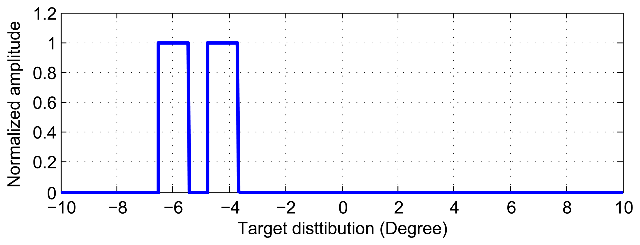
In this subsection, we present the simulation results under different noise levels. The simulation scene is shown in Figure 4. The two targets locate at −6° and −4.2°, with their corresponding amplitude of the same value as 1. Some simulation parameters are shown in Table 1. Samples in the 3 dB beam width is about 573.
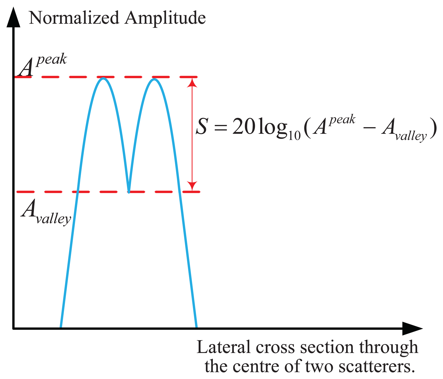
In order to quantify and compare the angular super-resolution performance of the TSVD method on the simulation data, relative error (ReErr), structure similarity (SSIM) [46] and the peak to valley point difference in dB are used in this section. They are defined as follows:
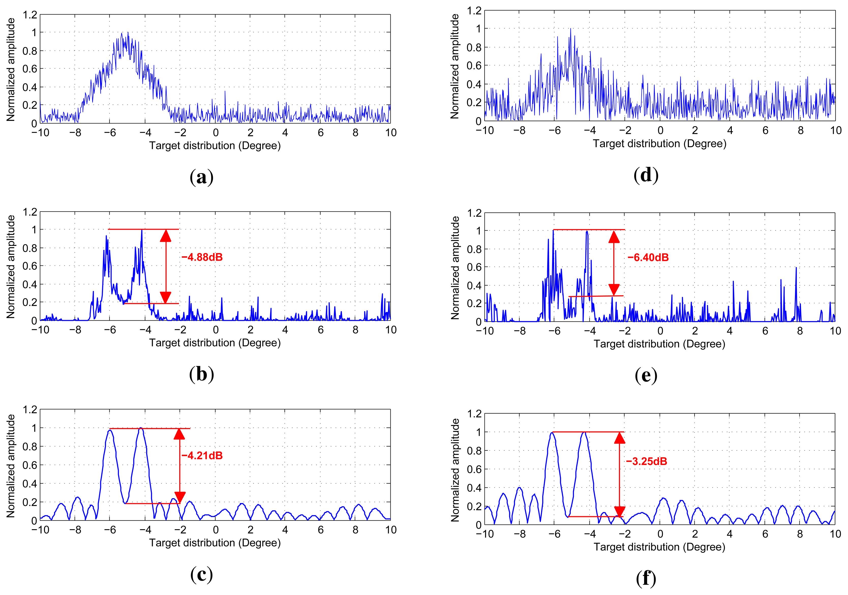
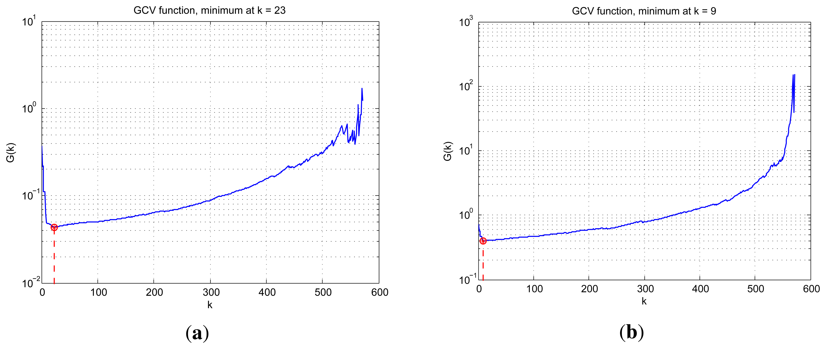
We use the code provided by the authors of [20] to implement the angular super-resolution. The code for TSVD was coded by us. In Figure 6, we display the restored angular super-resolution radar image from different methods. The echo data with different noise levels are shown in the top row of Figure 6. From the top row Figure 6, we can see that the amplitude of the received signal is proportional to the antenna pattern. The two targets are close enough, the response of the two targets are proportional to two replicas of the antenna pattern. This phenomenon brings a great difficulty in improving the angular resolution of scanning radar. The angular super-resolution results of Guan's method and the proposed method are shown in middle and bottom row of Figure 6, respectively. The choice of truncation parameter adaptively is out scope of this paper. For the truncated parameter k required in proposed method, we selected it using GCV method. The improvement of the proposed method compared to Guan's method. Figure 7 shows the functional value of function with respect to the truncated parameter k. Figure 7a corresponds to the GCV function curve under noise level SNR = 10 dB while Figure 7b shows the GCV curve under noise level SNR = 0 dB where the truncated parameters are also presented, which is utilized in the simulation. In Figure 6, the proposed method gives the super-resolution results where the spikes of targets look fairly separated whereas in the angular super-resolution results using the Guan's method, the spikes of the targets looks more connected. The values of peak to valley difference in dB are given in the Figure 6. The difference of peak to valley in dB is between 0 and −∞, where 0 means the angular super-resolution method can fully separate two closely spaced targets. This indicates that the larger value of peak to valley in dB, the better performance of the proposed angular super-resolution method in terms of super-resolution performance.
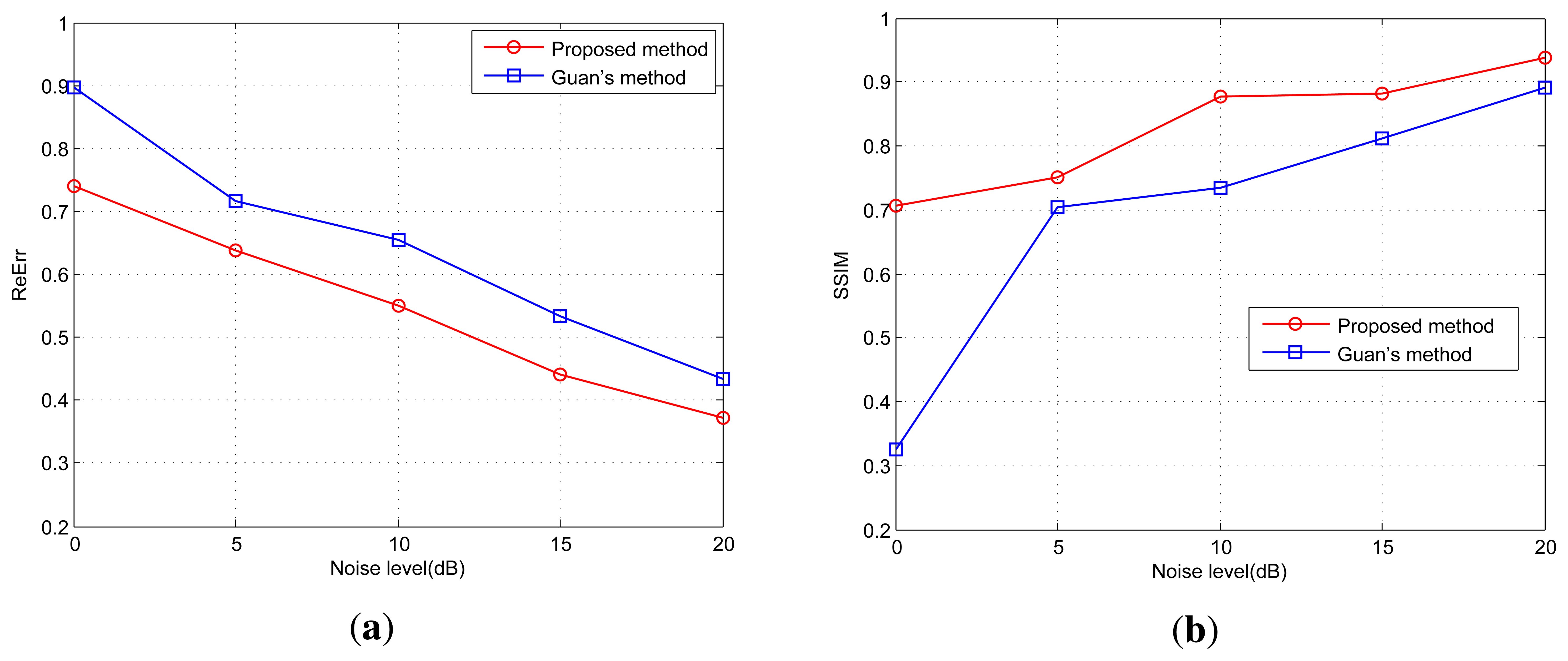
In addition, the angular super-resolution results by the proposed method have both lower ReErr and and higher SSIM than that by the Guan's method. Figure 8 presents the evolution of the ReErr and the SSIM with different SNRs. Figure 8a presents the ReErr result, whose ideal value is 0. When the value of the ReErr gets smaller, the precision of the angular super-resolution method is better. The metric SSIM is a quality measurement between the angular super-resolution result and the original scene. The larger value of the SSIM, the better performance of the proposed angular super-resolution method in terms of quality. It is clear that the proposed method gives better results than Guan's method.
4.2. Experimental Results
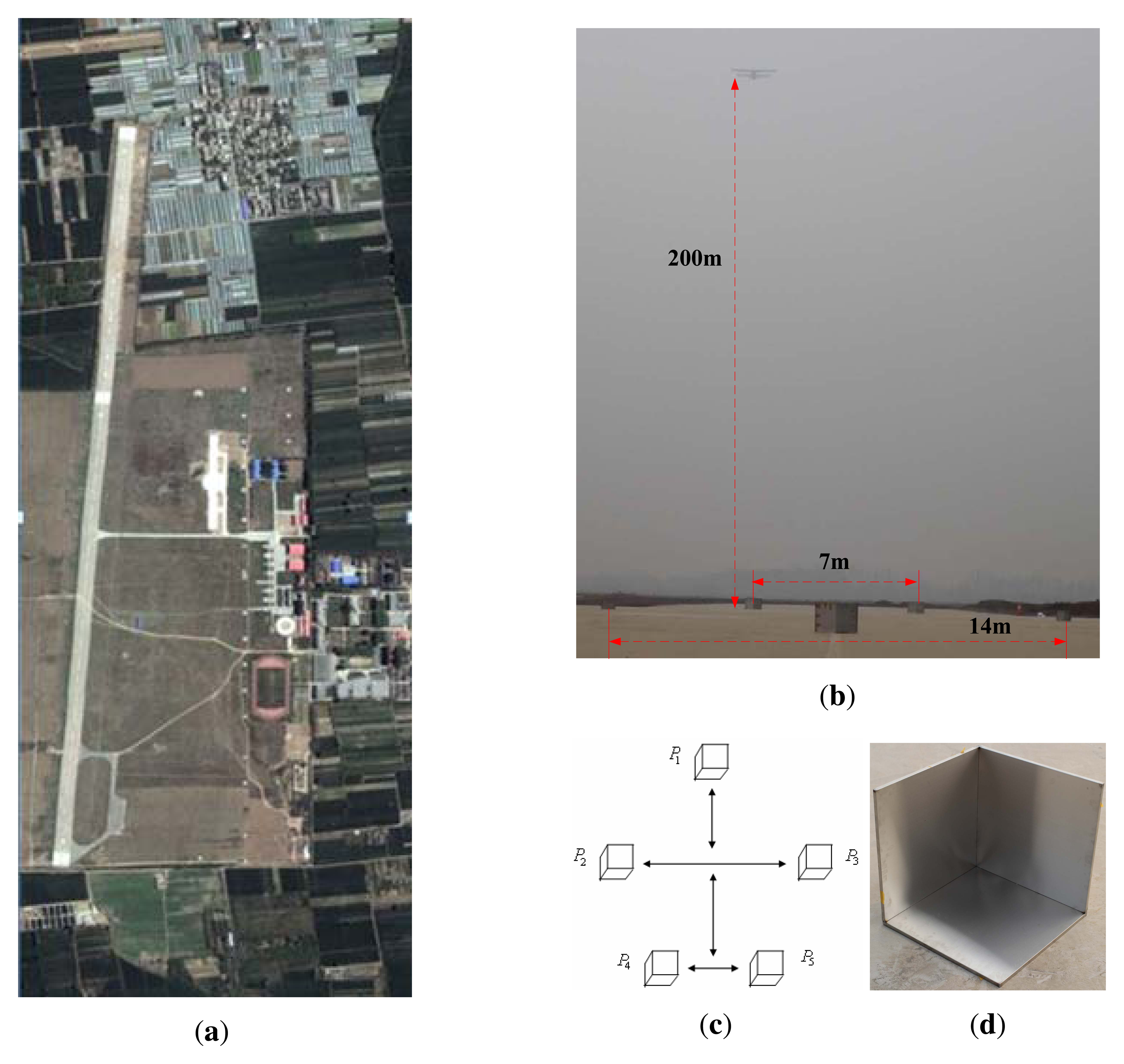
In this subsection, we present the experiment results illustrating the performance of the truncated singular value method for forward looking radar imaging and its application for adverse weather aircraft landing. Figure 9a shows the optical image of imaging scene. Figure 9b shows the position of the five corner reflectors and the distance between the reflectors. The height of the radar platform is about 200 m. The geometric relationship between the reflectors is shown in Figure 9c. Figure 9d shows the enlargement of trihedral reflector.
The experiment parameters are shown in Table 2. We first acquire the data according to the traditional sampling. Then, the range compression and range cell migration are applied to the echo data with the traditional approaches [20,39], and the corresponding result shown in Figure 10a. Figure 10b,c present the angular super-resolution results using the Guan's method and the proposed method, respectively. It can be seen that the proposed method has a better performance in terms of angular resolution. This is the fact that the TSVD method is able to suppress the noise amplification. We can also see that the angular super-resolution result obtained using the Guan's method can not resolve the reflectors, which locates in the same range cell but different angular cells. Therefore, we believe that the TSVD method for angular super-resolution in aircraft landing is useful in real applications.
5. Conclusions
A forward looking scanning radar imaging method using truncated singular value decomposition and its application for adverse weather aircraft landing are presented in this paper. After presenting and analyzing the signal model of forward looking scanning radar, we first convert the angular super-resolution imaging task into an equivalent deconvolution problem. In order to overcome the ill-posed nature of the deconvolution problem, we chose to compute a corresponding approximate solution by chopping off those SVD components that are dominated by the noise. The selection of the truncation parameter is based on GCV method. Compared with the Guan's method, the presented method improves the angular super-resolution performance in terms of precision. Simulation results indicate that the proposed method is effective in improving the angular resolution of scanning radar. The proposed method can also be applied to other inverse problem that are based on deconvolution. However, there are still some issues needed to be studied in angular super-resolution based on deconvlution method. Future work will study how to chose the truncation parameter adaptively and study the robustness of the deconvolution algorithm for angular super-resolution under low SNR levels.
Acknowledgements
This work was supported by the National Natural Science Foundation of China (No. 61201272).
Author Contributions
Yulin Huang: Field data acquisitions, project managing and managing; Yuebo Zha: Field data acquisitions, algorithm developing, data processing, writing of the paper; Yue Wang: Data processing; Jianyu Yang: Field data acquisitions, Project managing and managing.
Conflicts of Interest
The authors declare no conflict of interest.
References
- Bennell, J.A.; Mesgarpour, M.; Potts, C.N. Airport runway scheduling. Ann. Oper. Res. 2013, 204, 249–270. [Google Scholar]
- Yahav, D.; Kranz, Y.; Ashkenazi, A.; Orenstein, I.; Waisman, T.; Abrahami, M. Aircraft Landing Assistance. U.S. Patent 8,687,056, 1 April 2014. [Google Scholar]
- Möller, H.; Sachs, G. Synthetic vision for enhancing poor visibility flight operations. IEEE Aerosp. Electron. Syst. Mag. 1994, 9, 27–33. [Google Scholar]
- Sadjadi, F.; Helgeson, M.; Radke, J.; Stein, G. Radar synthetic vision system for adverse weather aircraft landing. IEEE Trans. Aerosp. Electron. Syst. 1999, 35, 2–14. [Google Scholar]
- Churnside, J.H.; Brown, E.D.; Parker-Stetter, S.; Horne, J.K.; Hunt, G.L.; Hillgruber, N.; Sigler, M.F.; Vollenweider, J.J. Airborne remote sensing of a biological hot spot in the Southeastern Bering Sea. Remote Sens. 2011, 3, 621–637. [Google Scholar]
- Peng, X.; Wang, Y.; Hong, W.; Tan, W.; Wu, Y. Autonomous navigation airborne forward-looking SAR high precision imaging with combination of pseudo-polar formatting and overlapped sub-aperture algorithm. Remote Sens. 2013, 5, 6063–6078. [Google Scholar]
- Liu, B.; Gu, J.C.; Chen, X.P.; Sun, X.W. Analysis of Heavy Cargo Air-Drop System and Its Simulation. J. Air Force Radar Acad. 2008, 2, 136–142. [Google Scholar]
- Richards, M.A. Iterative noncoherent angular superresolution [radar]. Proceedings of the 1988 IEEE National Radar Conference, Ann Arbor, MI, USA, 20–21 April 1988; pp. 100–105.
- Uttam, S.; Goodman, N.A. Superresolution of Coherent Sources in Real-Beam Data. IEEE Trans. Aerosp. Electron. Syst. 2010, 46, 1557–1566. [Google Scholar]
- Gambardella, A.; Migliaccio, M. On the superresolution of microwave scanning radiometer measurements. IEEE Geosci. Remote Sens. Lett. 2008, 5, 796–800. [Google Scholar]
- Lenti, F.; Nunziata, F.; Migliaccio, M.; Rodriguez, G. Two-Dimensional TSVD to Enhance the Spatial Resolution of Radiometer Data. IEEE Trans. Geosci. Remote Sens. 2014, 52, 2450–2458. [Google Scholar]
- Almeida, M.S.; Figueiredo, M.A. Deconvolving images with unknown boundaries using the alternating direction method of multipliers. IEEE Trans. Image Process. 2013, 22, 3074–3086. [Google Scholar]
- Orieux, F.; Sepulveda, E.; Loriette, V.; Dubertret, B.; Olivo-Marin, J.C. Bayesian estimation for optimized structured illumination microscopy. IEEE Trans. Image Process. 2012, 21, 601–614. [Google Scholar]
- Chan, S.; Khoshabeh, R.; Gibson, K.; Gill, P.; Nguyen, T. An Augmented Lagrangian Method for Total Variation Video Restoration. IEEE Trans. Image Process. 2011, 20, 3097–3111. [Google Scholar]
- Estatico, C.; Pastorino, M.; Randazzo, A. A novel microwave imaging approach based on regularization in Lp Banach spaces. IEEE Trans. Antennas Propag. 2012, 60, 3373–3381. [Google Scholar]
- Autieri, R.; Ferraiuolo, G.; Pascazio, V. Bayesian regularization in nonlinear imaging: reconstructions from experimental data in nonlinearized microwave tomography. IEEE Trans. Geosci. Remote Sens. 2011, 49, 801–813. [Google Scholar]
- Piles, M.; Camps, A.; Vall-Llossera, M.; Talone, M. Spatial-Resolution enhancement of SMOS data: A deconvolution-based approach. IEEE Trans. Geosci. Remote Sens. 2009, 47, 2182–2192. [Google Scholar]
- Ramani, S.; Fessler, J.A. A splitting-based iterative algorithm for accelerated statistical X-ray CT reconstruction. IEEE Trans. Med. Imaging 2012, 31, 677–688. [Google Scholar]
- Weller, D.S.; Ramani, S.; Fessler, J.A. Augmented Lagrangian with Variable Splitting for Faster Non-Cartesian-SPIRiT MR Image Reconstruction. IEEE Trans. Med. Imaging 2014, 33, 351–361. [Google Scholar]
- Guan, J.; Yang, J.; Huang, Y.; Li, W. Maximum a posteriori-based angular superresolution for scanning radar imaging. IEEE Trans. Aerosp. Electron. Syst. 2014, 50, 2389–2398. [Google Scholar]
- Zha, Y.; Huang, Y.; Sun, Z.; Wang, Y.; Yang, J. Bayesian Deconvolution for Angular Super-Resolution in Forward-Looking Scanning Radar. Sensors 2015, 15, 6924–6946. [Google Scholar]
- Golub, G.H.; Hansen, P.C.; O'Leary, D.P. Tikhonov regularization and total least squares. SIAM J. Matrix Anal. Appl. 1999, 21, 185–194. [Google Scholar]
- Winters, D.W.; van Veen, B.D.; Hagness, S.C. A sparsity regularization approach to the electromagnetic inverse scattering problem. IEEE Trans. Antennas Propag. 2010, 58, 145–154. [Google Scholar]
- Mojabi, P.; LoVetri, J.; Shafai, L. A multiplicative regularized Gauss—Newton inversion for shape and location reconstruction. IEEE Trans. Antennas Propag. 2011, 59, 4790–4802. [Google Scholar]
- Zhang, J.; Zhong, P.; Chen, Y.; Li, S. L1/2-Regularized Deconvolution Network for the Representation and Restoration of Optical Remote Sensing Images. IEEE Trans. Geosci. Remote Sens. 2014, 52, 2617–2627. [Google Scholar]
- Kwon, T.J.; Li, J.; Wong, A. ETVOS: An enhanced total variation optimization segmentation approach for SAR sea-ice image segmentation. IEEE Trans. Geosci. Remote Sens. 2013, 51, 925–934. [Google Scholar]
- Yildirim, S.; Cemgil, A.; Aktar, M.; Ozakin, Y.; Ertuzun, A. A Bayesian Deconvolution Approach for Receiver Function Analysis. IEEE Trans. Geosci. Remote Sens. 2010, 48, 4151–4163. [Google Scholar]
- Yu, Y.; Carin, L. Three-Dimensional Bayesian inversion with application to subsurface sensing. IEEE Trans. Geosci. Remote Sens. 2007, 45, 1258–1270. [Google Scholar]
- Zhang, L.; Qiao, Z.J.; Xing, M.D.; Sheng, J.L.; Guo, R.; Bao, Z. High-Resolution ISAR imaging by exploiting sparse apertures. IEEE Trans. Antennas Propag. 2012, 60, 997–1008. [Google Scholar]
- Shea, J.D.; van Veen, B.D.; Hagness, S.C. A TSVD analysis of microwave inverse scattering for breast imaging. IEEE Trans. Biomed. Eng. 2012, 59, 936–945. [Google Scholar]
- Fang, Q.; Meaney, P.M.; Paulsen, K.D. Singular value analysis of the Jacobian matrix in microwave image reconstruction. IEEE Trans. Antennas Propag. 2006, 54, 2371–2380. [Google Scholar]
- Lenti, F.; Nunziata, F.; Migliaccio, M.; Rodriguez, G. Two-Dimensional TSVD to Enhance the Spatial Resolution of Radiometer Data. IEEE Trans. Geosci. Remote Sens. 2014, 52, 2450–2458. [Google Scholar]
- Kuo, C.H.; Moghaddam, M. Scattering from multilayer rough surfaces based on the extended boundary condition method and truncated singular value decomposition. IEEE Trans. Antennas Propag. 2006, 54, 2917–2929. [Google Scholar]
- Rodriguez, J.L.; Taboada, J.M.; Araujo, M.G.; Obelleiro Basteiro, F.; Landesa, L.; Garcia-Tunon, J. On the use of the singular value decomposition in the fast multipole method. IEEE Trans. Antennas Propag. 2008, 56, 2325–2334. [Google Scholar]
- Barriere, P.; Idier, J.; Goussard, Y.; Laurin, J. Fast Solutions of the 2D Inverse Scattering Problem Based on a TSVD Approximation of the Internal Field for the Forward Model. IEEE Trans. Antennas Propag. 2010, 58, 4015–4024. [Google Scholar]
- Zhang, X.; Wang, S. Image restoration using truncated SVD filter bank based on an energy criterion. IEE Proc. Vis. Image Signal Process. 2006, 153, 825–836. [Google Scholar]
- Hansen, P.C. Discrete Inverse Problems: Insight and Algorithms; SIAM: Philadelphia, PA, USA, 2010; Volume 7. [Google Scholar]
- Vogel, C.R. Computational Methods for Inverse Problems; SIAM: Philadelphia, PA, USA, 2002; Volume 23. [Google Scholar]
- Li, W.; Yang, J.; Huang, Y. Keystone transform-based space-variant range migration correction for airborne forward-looking scanning radar. Electron. Lett. 2012, 48, 121–122. [Google Scholar]
- Tello Alonso, M.; Lopez-Dekker, P.; Mallorqui, J. A Novel Strategy for Radar Imaging Based on Compressive Sensing. IEEE Trans. Geosci. Remote Sens. 2010, 48, 4285–4295. [Google Scholar]
- Ng, M.K.; Chan, R.H.; Tang, W.C. A fast algorithm for deblurring models with Neumann boundary conditions. SIAM J. Sci. Comput. 1999, 21, 851–866. [Google Scholar]
- Varah, J.M. On the numerical solution of ill-conditioned linear systems with applications to ill-posed problems. SIAM J. Numer. Anal. 1973, 10, 257–267. [Google Scholar]
- Stewart, G.W. On the early history of the singular value decomposition. SIAM Rev. 1993, 35, 551–566. [Google Scholar]
- Bates, D.M.; Wahba, G. A Truncated Singular Value Decomposition and Other Methods for Generalized Cross-Validation; p. TR0715. Department of Statistics, University of Wisconsin: Madison, WI, USA, 1983. [Google Scholar]
- Craven, P.; Wahba, G. Smoothing noisy data with spline functions. Numer. Math. 1978, 31, 377–403. [Google Scholar]
- Wang, Z.; Bovik, A.C. Mean squared error: love it or leave it? A new look at signal fidelity measures. IEEE Signal Process. Mag. 2009, 26, 98–117. [Google Scholar]


| Parameters | Value | Units |
|---|---|---|
| Carrier frequency | 10 | GHz |
| Band width | 75 | MHz |
| Pulse duration | 2 | μs |
| Pulse repetition frequency | 1000 | Hz |
| Antenna scanning velocity | 30 | °/s |
| Antenna scanning area | −10 ∼+10 | ° |
| Main-lobe beam width | 3 | ° |
| Parameters | Value | Units |
|---|---|---|
| Carrier frequency | 30.75 | GHz |
| Band width | 40 | MHz |
| Pulse duration | 2 | μs |
| Pulse repetition frequency | 4000 | Hz |
| Antenna scanning velocity | 60 | °/s |
| Main-lobe beam width | 4 | ° |
| Radar platform height | 200 | m |
| Antenna scanning area | −35∼+35 | ° |
© 2015 by the authors; licensee MDPI, Basel, Switzerland. This article is an open access article distributed under the terms and conditions of the Creative Commons Attribution license (http://creativecommons.org/licenses/by/4.0/).
Share and Cite
Huang, Y.; Zha, Y.; Wang, Y.; Yang, J. Forward Looking Radar Imaging by Truncated Singular Value Decomposition and Its Application for Adverse Weather Aircraft Landing. Sensors 2015, 15, 14397-14414. https://doi.org/10.3390/s150614397
Huang Y, Zha Y, Wang Y, Yang J. Forward Looking Radar Imaging by Truncated Singular Value Decomposition and Its Application for Adverse Weather Aircraft Landing. Sensors. 2015; 15(6):14397-14414. https://doi.org/10.3390/s150614397
Chicago/Turabian StyleHuang, Yulin, Yuebo Zha, Yue Wang, and Jianyu Yang. 2015. "Forward Looking Radar Imaging by Truncated Singular Value Decomposition and Its Application for Adverse Weather Aircraft Landing" Sensors 15, no. 6: 14397-14414. https://doi.org/10.3390/s150614397