
An Analytical Model for Squeeze-Film Damping of Perforated Torsional Microplates Resonators

Abstract
:1. Introduction

| Publication Year | Reference | Contributions and Structure Assumed in Model |
|---|---|---|
| 2001 | Veijola and Mattila [16] | An extended Reynolds equation is first derived by adding an additional “leakage” term due to the perforations. Rigid rectangular microplate is considered. The microplate is operated in normal direction to the substrate. |
| 2003 | Bao et al. [17] | A modified Reynolds equation under the assumption of incompressible flow is derived by adding a penetrating term to fluid continuity equation. Rigid rectangular microplate is considered. The microplate is operated in normal direction to the substrate. |
| 2006 | Veijola [18] | The perforation effect is model by calculating the equivalent electrical impedance for squeeze film damping, the flow resistance of the holes, end effect of the holes and the compressibility effect. Rigid rectangular microplate is considered. The microplate is operated in normal direction to the substrate. |
| 2007 | Pandey et al. [19] | Bao’s model [17] was extended to include the compressibility effect and rarefaction effect. Rigid and flexible rectangular microplates are considered. The microplate is operated in normal direction to the substrate. |
| 2014 | Li et al. [20] | The modified Reynolds equation presented by Pandey et al. [19] was extended to model the rigid and flexible circular microplates. The microplate is operated in normal direction to the substrate. |
| Proposed model | The modified Reynolds equation presented by Pandey et al. [19] was extended to model the torsion microplate. |
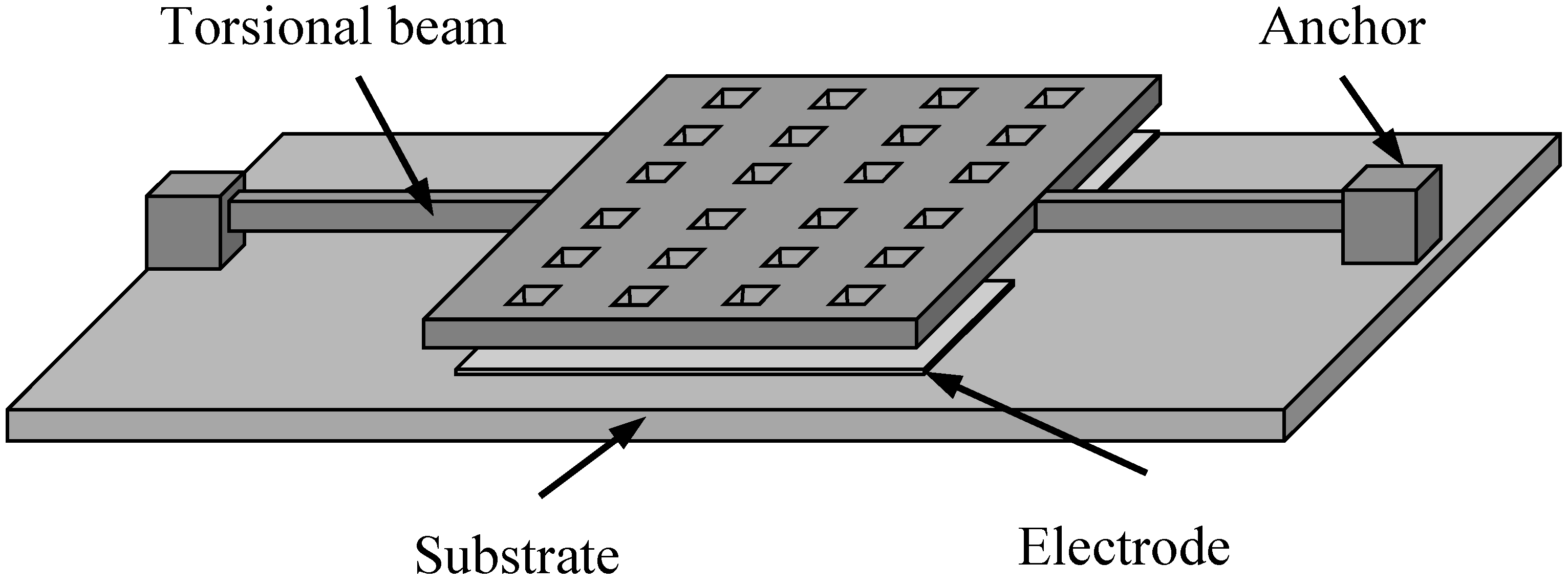
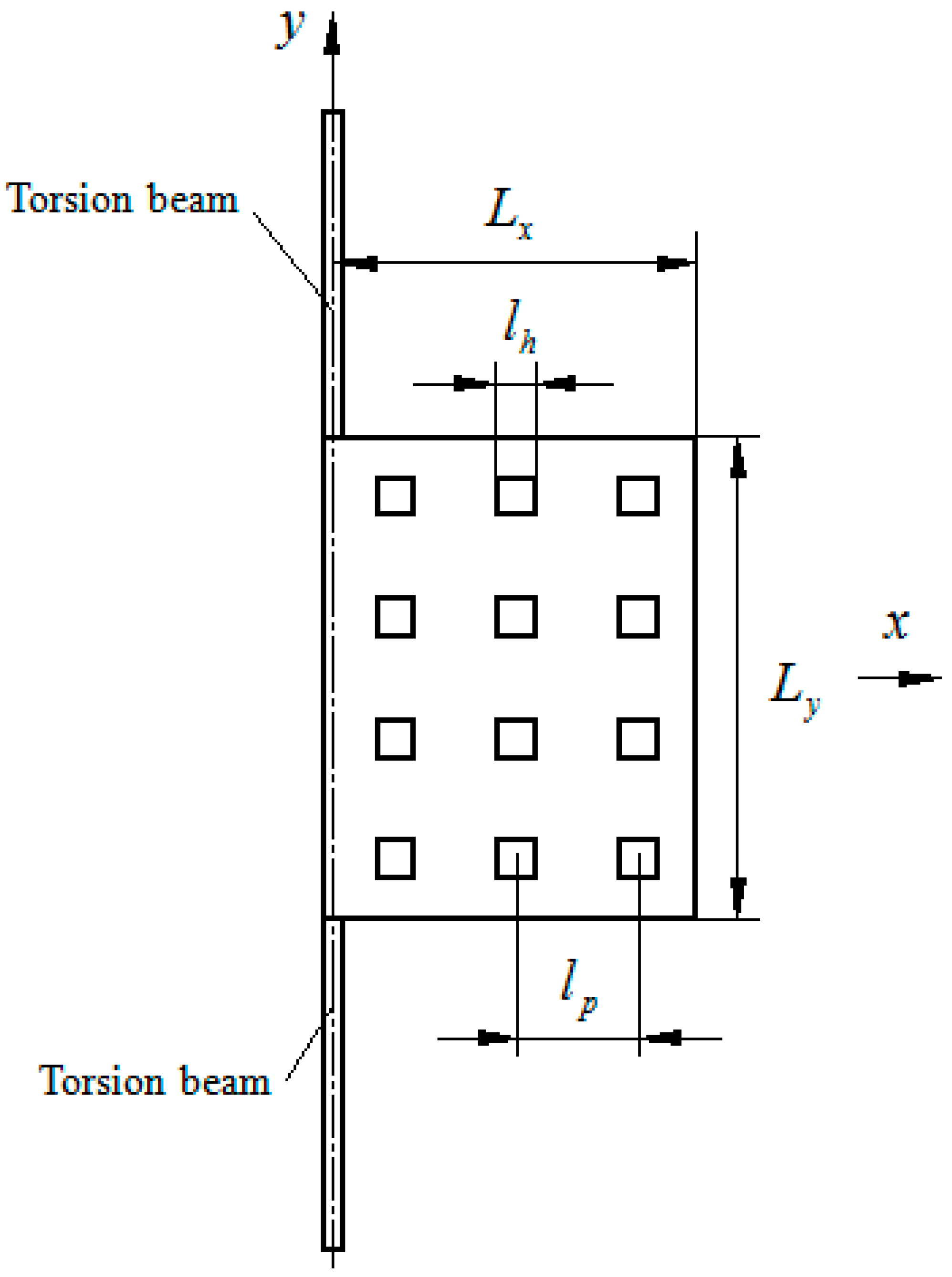
2. Analytical Modeling of Squeeze-Film Damping for the First Type Resonator
2.1. Governing Equations
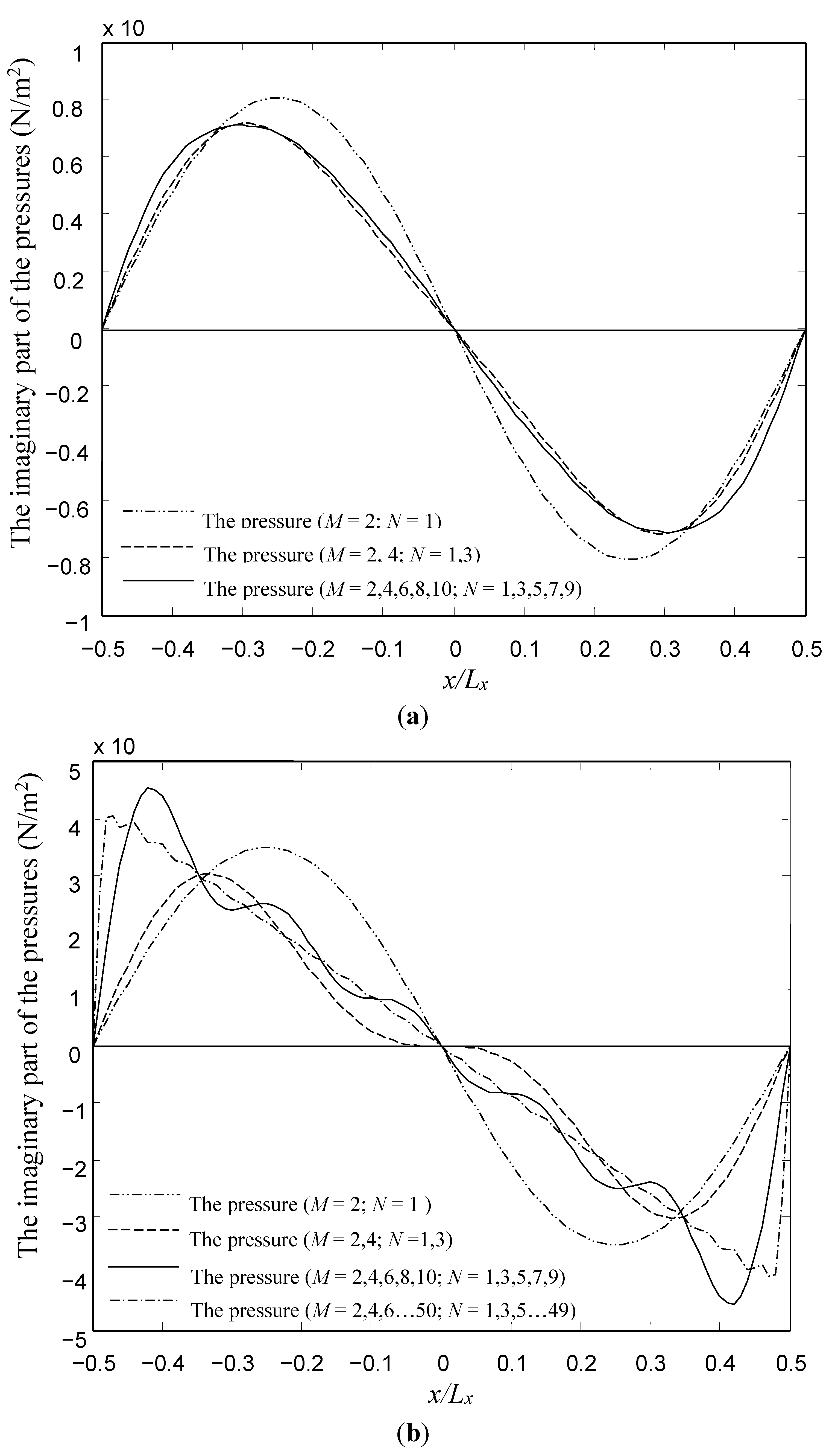
2.2. Analytical Model for the Type I Device
3. Analytical Modeling of Squeeze-Film Damping for the Second Type Resonator
| Devices | The Damping Constant | The Spring Constant | |
|---|---|---|---|
| Type I | |||
| Type II | |||
| and | |||
4. Validation and Discussions
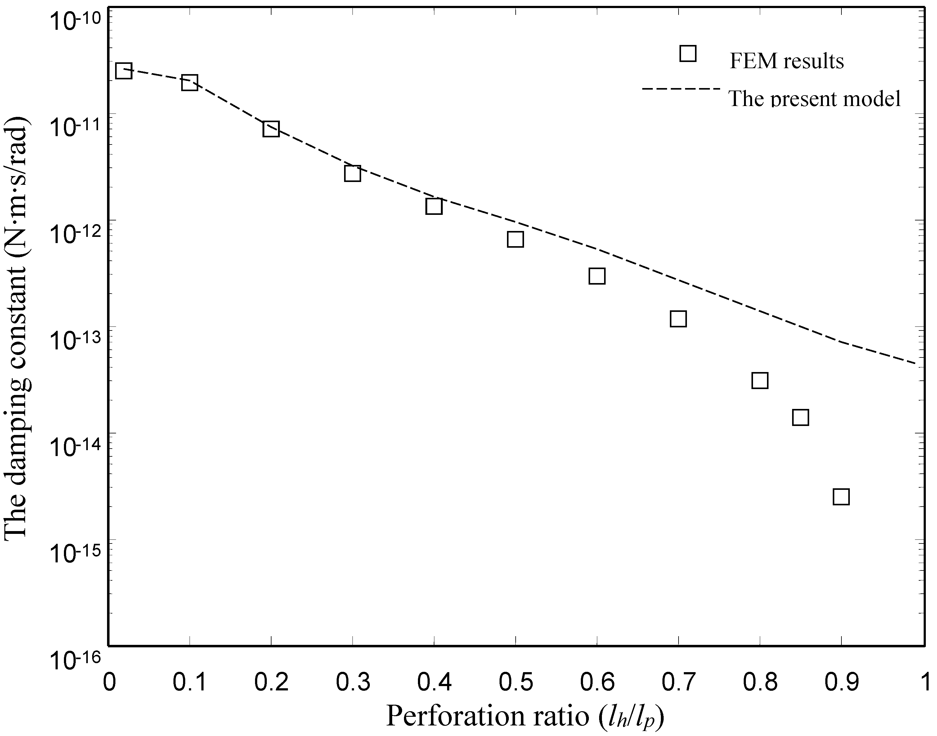
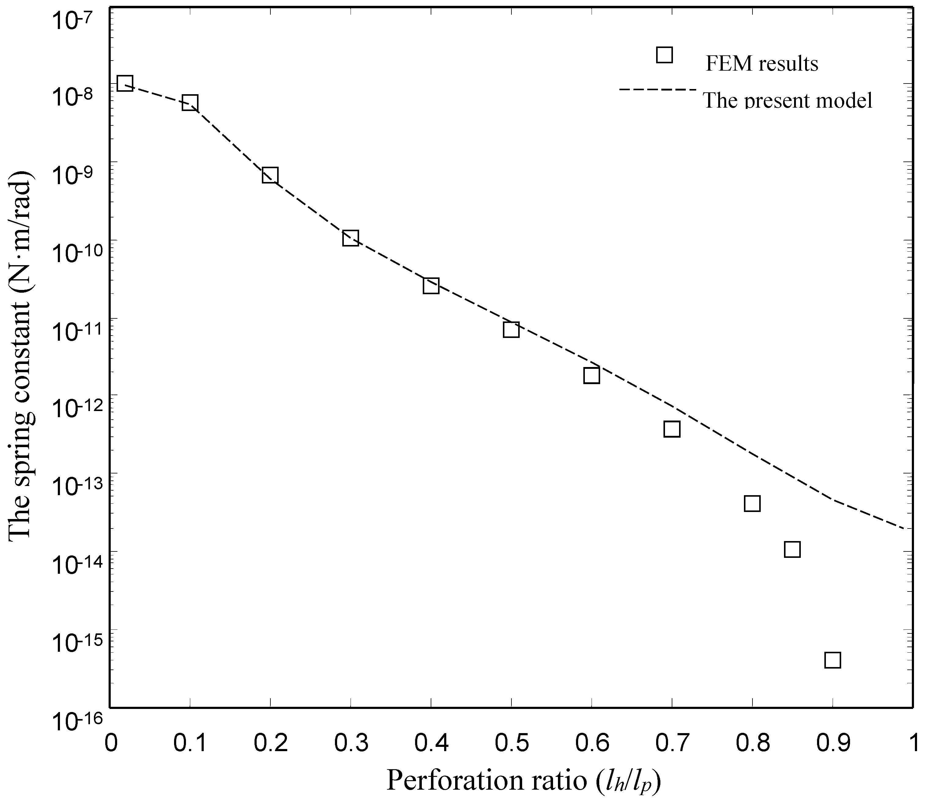
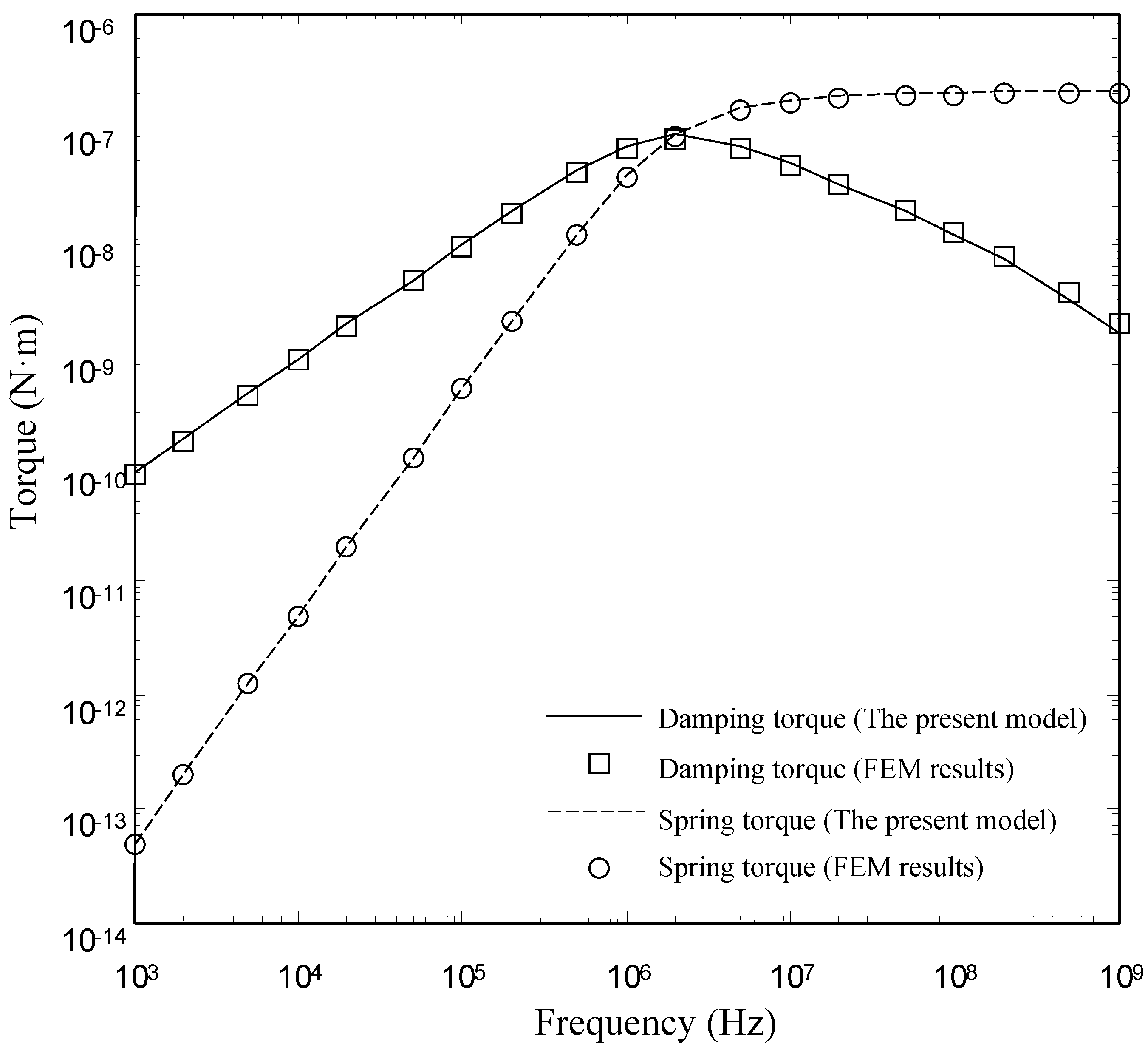
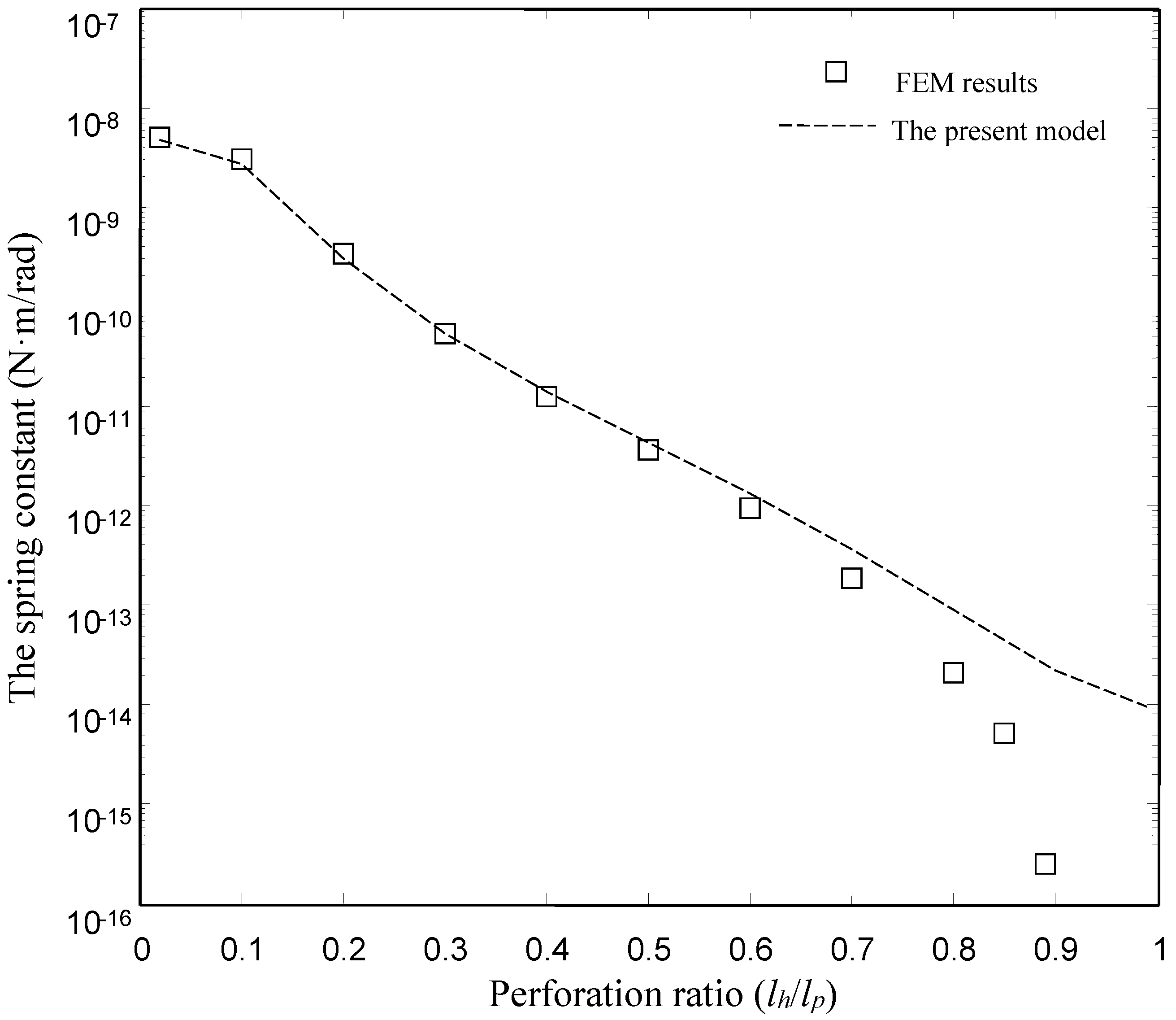
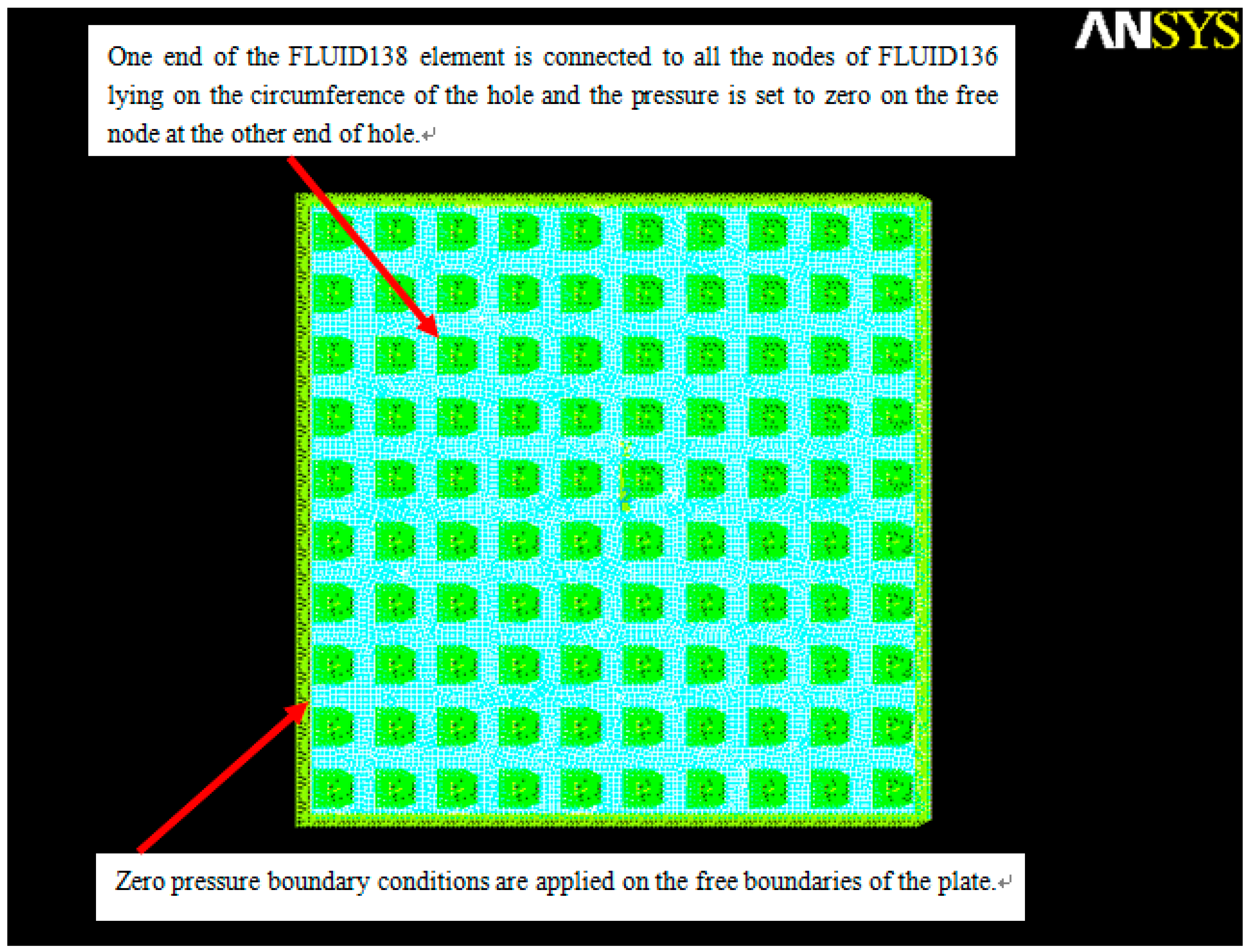
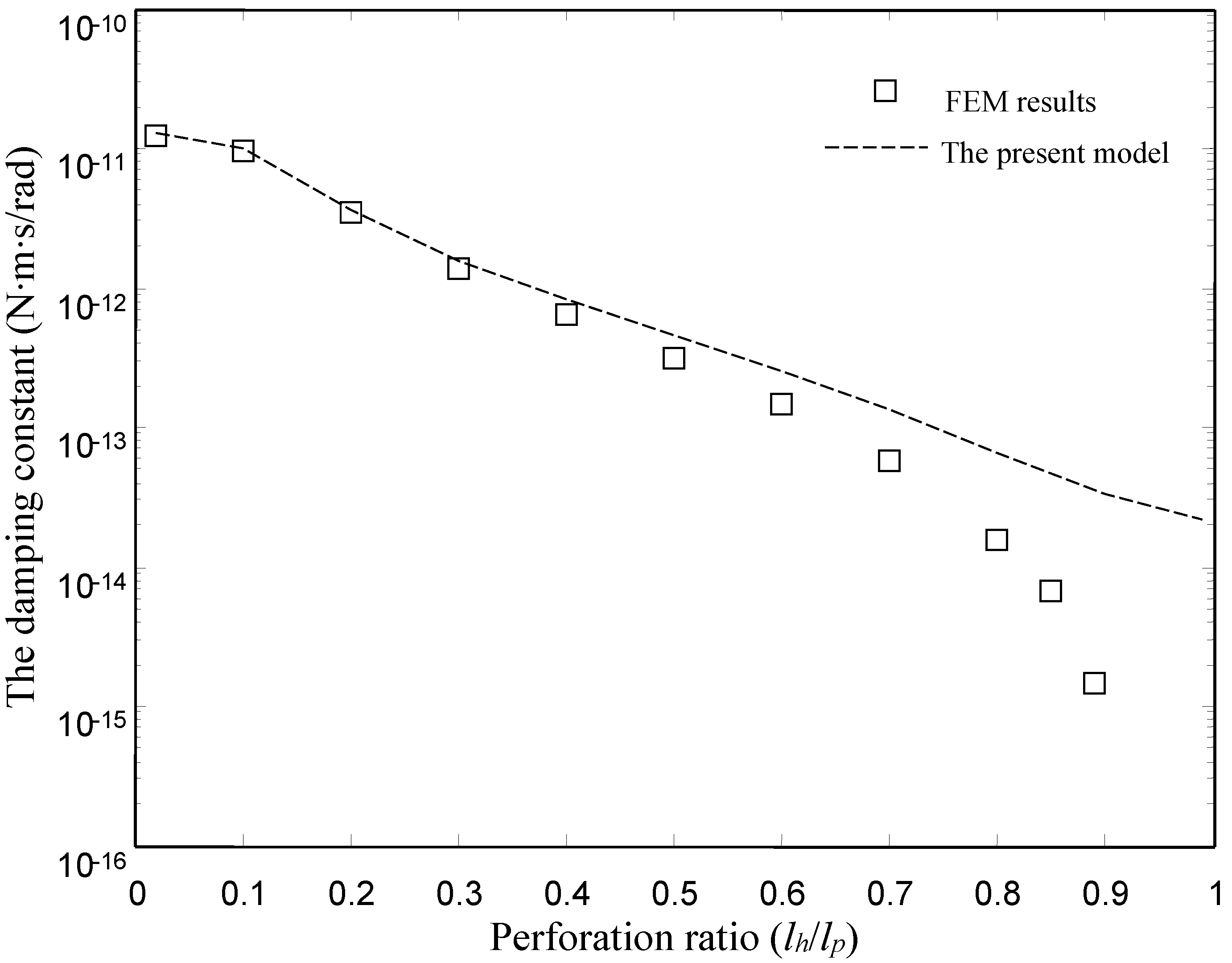
4.1. Comparsions with the FEM Results for the Type I Torsion Microplate
| Symbol | Description | Values | Unit |
|---|---|---|---|
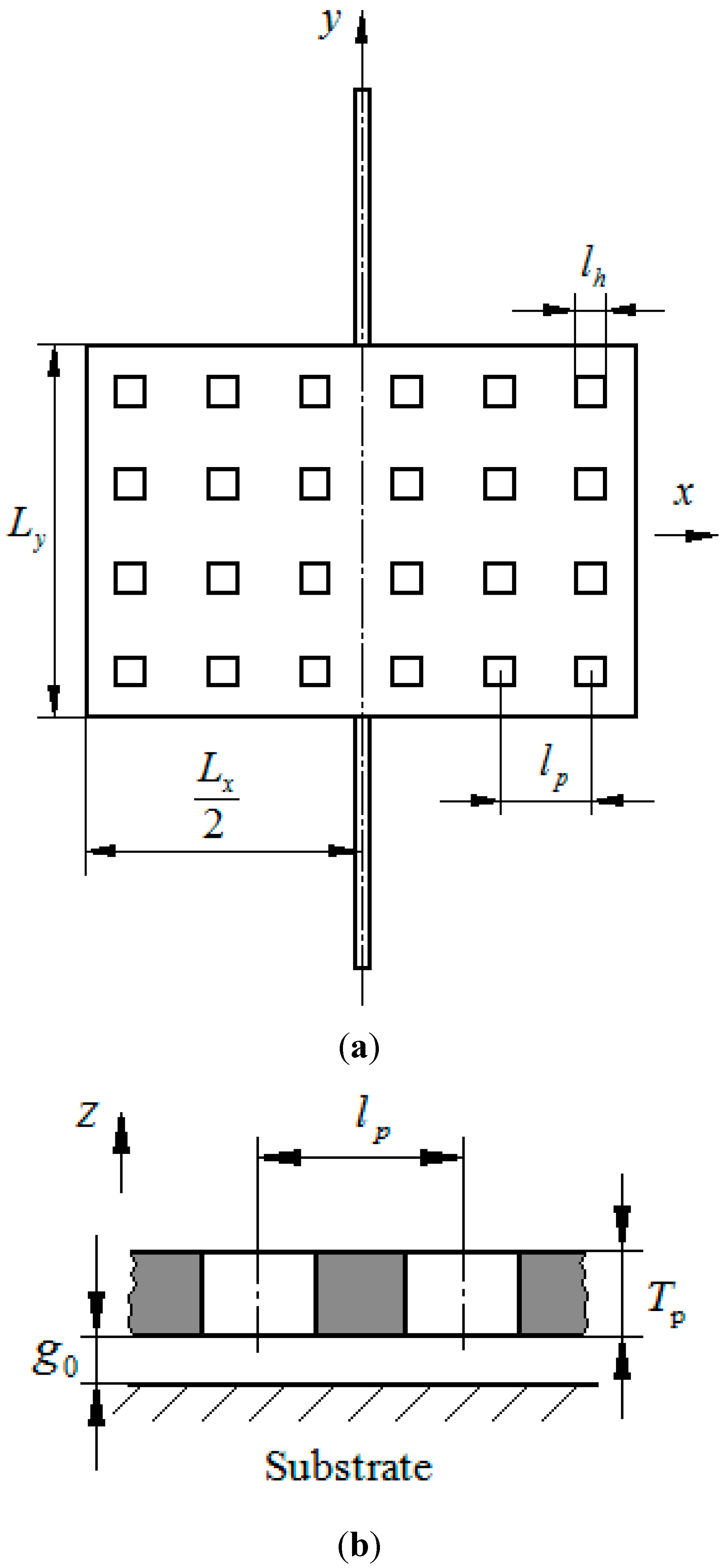
| Length of the torsion microplate | 500 | µm | |
| Widthth of the torsion microplate | 500 | µm | |
| Thickness of the torsion microplate | 10 | µm | |
| The total number of the holes along x-direction | 10 | ||
| The total number of the holes along y-direction | 10 | ||
| The pitch of the holes | 50 | µm | |
| Gap spacing | 5 | µm | |
| Ambient pressure | 1.013 × 10⁵ | N/m2 | |
| Viscosity coefficient | 1.83 × 10⁻⁵ | N·s/m2 |


| The Damping Constant | The Spring Constant | |||
|---|---|---|---|---|
| FEM Model | The Present Model | FEM Model | The Present Model | |
| 0.02 | 2.51 × 10⁻¹¹ | 2.52 × 10⁻¹¹ | 9.26 × 10⁻⁹ | 9.37 × 10⁻⁹ |
| 0.1 | 1.94 × 10⁻¹¹ | 1.97 × 10⁻¹¹ | 5.39 × 10⁻⁹ | 5.46 × 10⁻⁹ |
| 0.2 | 6.93 × 10⁻¹² | 7.18 × 10⁻¹² | 6.20 × 10⁻¹⁰ | 6.20 × 10⁻¹⁰ |
| 0.3 | 2.73 × 10⁻¹² | 3.12 × 10⁻¹² | 9.63 × 10⁻¹¹ | 1.07 × 10⁻¹⁰ |
| 0.4 | 1.29 × 10⁻¹² | 1.65 × 10⁻¹² | 2.31 × 10⁻¹¹ | 2.87 × 10⁻¹¹ |
| 0.5 | 6.37 × 10⁻¹³ | 9.30 × 10⁻¹³ | 6.47 × 10⁻¹² | 8.86 × 10⁻¹² |
| 0.6 | 2.96 × 10⁻¹³ | 5.17 × 10⁻¹³ | 1.68 × 10⁻¹² | 2.68 × 10⁻¹² |
| 0.7 | 1.16 × 10⁻¹³ | 2.72 × 10⁻¹³ | 3.38 × 10⁻¹³ | 7.30 × 10⁻¹³ |
| 0.8 | 3.07 × 10⁻¹⁴ | 1.35 × 10⁻¹³ | 3.82 × 10⁻¹⁴ | 1.80 × 10⁻¹³ |
| 0.85 | 1.35 × 10⁻¹⁴ | 1.02 × 10⁻¹³ | 9.40 × 10⁻¹⁵ | 1.13 × 10⁻¹³ |
| 0.9 | 2.44 × 10⁻¹⁵ | 6.92 × 10⁻¹⁴ | 3.71 × 10⁻¹⁶ | 4.64 × 10⁻¹⁴ |
| 0.99 | - | 4.50 × 10⁻¹⁴ | - | 1.97 × 10⁻¹⁴ |


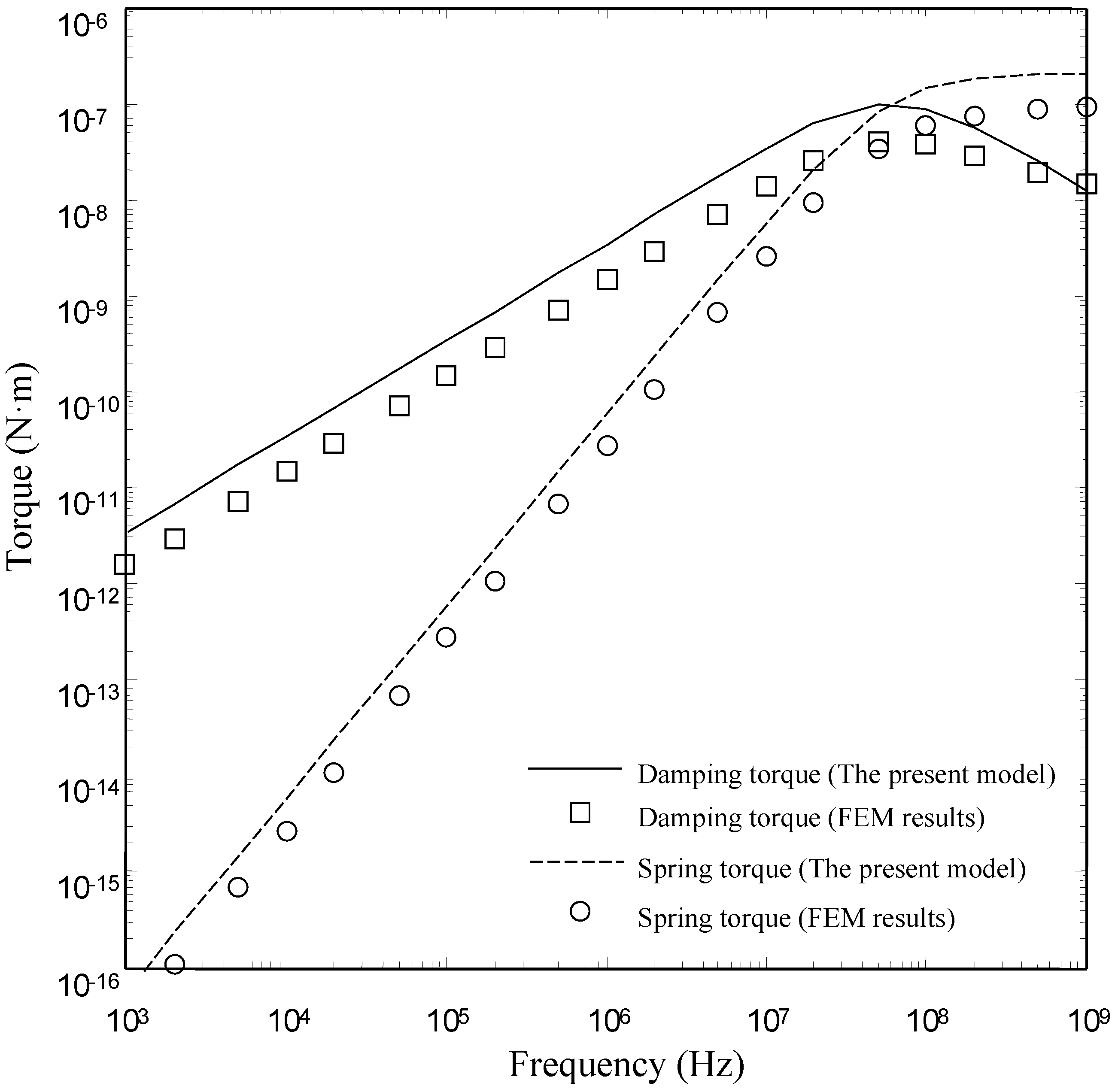
4.2. Comparsions with the FEM Results for the Type II Torsion Microplate

| The Damping Constant | The Spring Constant | |||
|---|---|---|---|---|
| FEM Model | The Present Model | FEM Model | The Present Model | |
| 0.02 | 1.26 × 10⁻¹¹ | 1.26 × 10⁻¹¹ | 4.63 × 10⁻⁹ | 4.67 × 10⁻⁹ |
| 0.1 | 9.71 × 10⁻¹² | 9.84 × 10⁻¹² | 2.69 × 10⁻⁹ | 2.73 × 10⁻⁹ |
| 0.2 | 3.47 × 10⁻¹² | 3.58 × 10⁻¹² | 3.10 × 10⁻¹⁰ | 3.10 × 10⁻¹⁰ |
| 0.3 | 1.37 × 10⁻¹² | 1.55 × 10⁻¹² | 4.82 × 10⁻¹¹ | 5.34 × 10⁻¹¹ |
| 0.4 | 6.42 × 10⁻¹³ | 8.18 × 10⁻¹³ | 1.15 × 10⁻¹¹ | 1.43 × 10⁻¹¹ |
| 0.5 | 3.19 × 10⁻¹³ | 4.59 × 10⁻¹³ | 3.24 × 10⁻¹² | 4.40 × 10⁻¹² |
| 0.6 | 1.48 × 10⁻¹³ | 2.54 × 10⁻¹³ | 8.39 ×10⁻¹³ | 1.32 × 10⁻¹² |
| 0.7 | 5.83 × 10⁻¹⁴ | 1.33 × 10⁻¹³ | 1.70 × 10⁻¹³ | 3.60 × 10⁻¹³ |
| 0.8 | 1.56 × 10⁻¹⁴ | 6.62 × 10⁻¹⁴ | 1.93 × 10⁻¹⁴ | 8.80 × 10⁻¹⁴ |
| 0.85 | 6.66 × 10⁻¹⁵ | 4.99 × 10⁻¹⁴ | 4.64 × 10⁻¹⁵ | 5.55 × 10⁻¹⁴ |
| 0.9 | 1.46 × 10⁻¹⁵ | 3.37 × 10⁻¹⁴ | 2.29 × 10⁻¹⁶ | 2.28 × 10⁻¹⁴ |
| 0.99 | - | 2.19 × 10⁻¹⁴ | - | 9.59 × 10⁻¹⁵ |
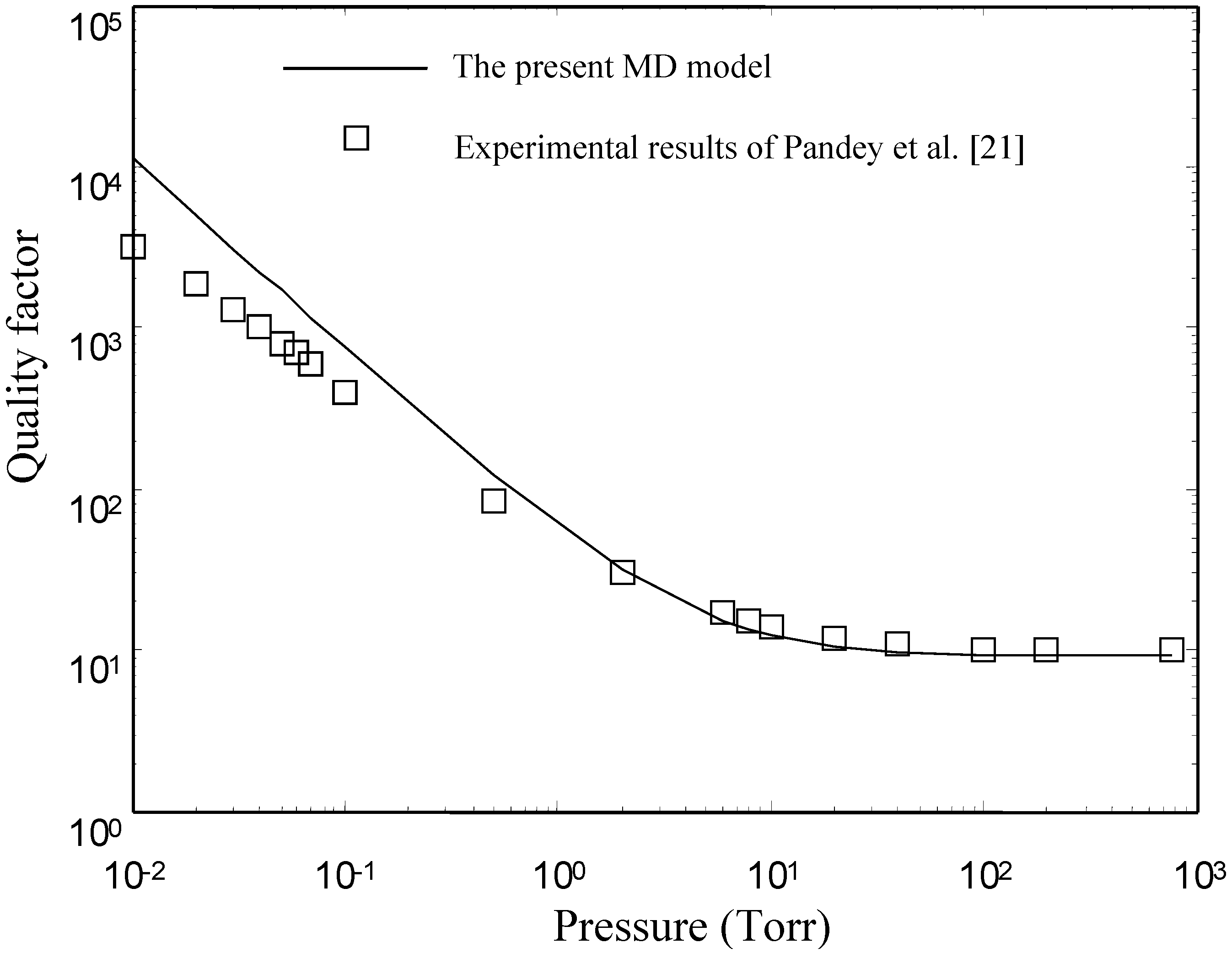
4.3. Comparsions with the Experimental Results of Pandey et al. [21]

5. Conclusions
- (1)
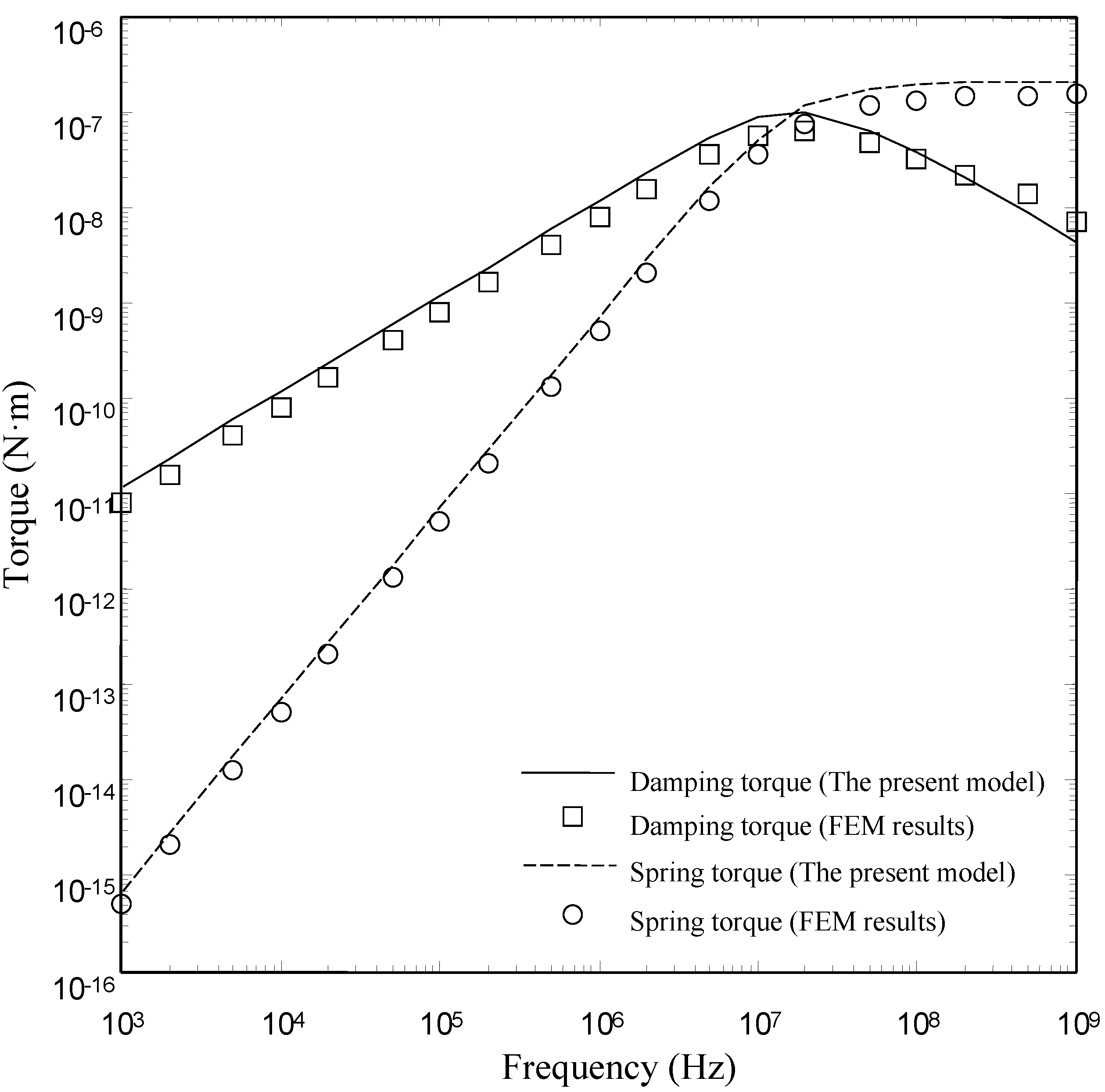
- The present model is valid for devices with smaller and medium perforation ratios. The present model gives good results for the devices with lh/lp ≤ 0.6. For the devices with lh/lp ≤ 0.6, the present model matches well with the numerical model over a wide range of frequency. However, there is a clear discrepancy between the FEM model and the present model at large perforation ratios.
- (2)
- The main assumption in this paper is the negligence of the inertial effect. The assumption limits the operating frequency range. Currently, we are extending this work to account for the inertial effect.
Acknowledgments
Author Contributions
Conflicts of Interest
References
- Schrag, G.; Wachutak, G. Accurate system-level damping model for highly perforated micromechanical devices. Sens. Actuators A Phys. 2004, 111, 222–228. [Google Scholar] [CrossRef]
- Pasquale, G.; de Veijola, T. Comparative numerical study of FEM methods solving gas damping in MEMS devices. Microfluid. Nanofluid. 2008, 5, 517–528. [Google Scholar] [CrossRef]
- Pasquale, G.; de Veijola, T.; Somà, A. Modelling and Validation of air damping in perforated gold and silicon MEMS plates. J. Micromech. Microeng. 2010, 20, 015010. [Google Scholar] [CrossRef]
- Feng, C; Zhao, Y; Liu, D.Q. Squeeze-film effects in MEMS devices with perforated plates for small amplitude vibration. Microsyst. Technol. 2007, 13, 625–633. [Google Scholar]
- Somà, A.; Pasquale, G.D. Numerical and experimental comparison of MEMS suspended plates dynamic behavior under squeeze film damping effect. Analog Integr. Circuits Signal Process. 2008, 57, 213–224. [Google Scholar] [CrossRef]
- Nigro, S.; Pagnotta, L.; Pantano, M.F. Analytical and numerical modeling of squeeze-film damping in perforated microstructures. Microfluid. Nanofluid. 2012, 12, 971–979. [Google Scholar] [CrossRef]
- Veijola, T.; Råback, P. Methods for solving gas damping problems in perforated microstructures using a 2D finite-element solver. Sensors 2007, 7, 1069–1090. [Google Scholar] [CrossRef]
- Skvor, Z. On acoustical resistance due to viscous losses in the air gap of electrostatic transducers. Acustica 1967, 19, 295–299. [Google Scholar]
- Bao, M.; Yang, H.; Sun, Y.; Wang, Y. Squeeze-film air damping of thick hole-plate. Sens. Actuators A Phys. 2002, 108, 212–217. [Google Scholar] [CrossRef]
- Mohite, S.S.; Kesari, H.; Sonti, V.R.; Pratap, R. Analytical solutions for the stiffness and damping coefficients of squeeze films in MEMS devices with perforated back plates. J. Micromech. Microeng. 2005, 15, 2083–2092. [Google Scholar] [CrossRef]
- Mohite, S.S.; Sonti, V.R.; Pratap, R. A compact squeeze-film model including inertia, compressibility, and rarefaction effects for perforated 3-D MEMS structures. J. Microelectromech. Syst. 2008, 17, 709–723. [Google Scholar] [CrossRef]
- Kwok, P.Y.; Weinberg, M.S.; Breuer, K.S. Fluid effects in vibrating micromachined structures. J. Microelectromech. Syst. 2005, 14, 770–781. [Google Scholar] [CrossRef]
- Homentcovschi, D.; Miles, R.N. Modelling of viscous damping of perforated planar micromechanical structures, Applications in acoustics. J. Acoust. Soc. Am. 2004, 116, 2939–2947. [Google Scholar] [CrossRef] [PubMed]
- Homentcovschi, D.; Miles, R.N. Viscous microstructural dampers with aligned holes: Design procedure including the edge correction. J. Acoust. Soc. Am. 2007, 122, 1556–1567. [Google Scholar] [CrossRef] [PubMed]
- Homentcovschi, D.; Murray, B.T.; Miles, R.N. An analytical formula and FEM simulations for the viscous damping of a periodic perforated MEMS microstructure outside the lubrication approximation. Microfluid. Nanofluid. 2010, 9, 865–879. [Google Scholar] [CrossRef]
- Veijola, T.; Mattila, T. Compact Squeeze-Film Damping Model for Perforated Surface. In Proceeding of the Transducers’01, Munich, Germany, 10–14 June 2001; pp. 1506–1509.
- Bao, M.; Yang, H.; Sun, Y.; Wang, Y. Modified Reynolds’ equation and analysis of squeeze-film air damping of perforated structures. J. Micromech. Microeng. 2003, 23, 795–800. [Google Scholar] [CrossRef]
- Veijola, T. Analytic damping model for an MEM perforation cell. Microfluid. Nanofluid. 2006, 2, 249–260. [Google Scholar] [CrossRef]
- Pandey, A.K.; Pratap, R.; Chau, F.S. Analytical solution of the modified Reynolds equations for squeeze film damping in perforated MEMS structures. Sens. Actuators A Phys. 2007, 135, 839–848. [Google Scholar] [CrossRef]
- Li, P.; Fang, Y.; Xu, F. Analytical modeling of squeeze-film damping for perforated circular microplates. J. Sound Vib. 2014, 333, 2688–2700. [Google Scholar] [CrossRef]
- Pandey, A.K.; Pratap, R.; Chau, F.S. Effect of pressure on fluid damping in MEMS torsional resonators with flow ranging from continuum to molecular regime. Exp. Mech. 2008, 48, 91–106. [Google Scholar] [CrossRef]
- Pandey, A.K.; Pratap, R. A semi-analytical model for squeeze-film damping including rarefaction in a MEMS torsion mirror with complex geometry. J. Micromech. Microeng. 2008, 18, 105003. [Google Scholar] [CrossRef]
© 2015 by the authors; licensee MDPI, Basel, Switzerland. This article is an open access article distributed under the terms and conditions of the Creative Commons Attribution license (http://creativecommons.org/licenses/by/4.0/).
Share and Cite
Li, P.; Fang, Y. An Analytical Model for Squeeze-Film Damping of Perforated Torsional Microplates Resonators. Sensors 2015, 15, 7388-7411. https://doi.org/10.3390/s150407388
Li P, Fang Y. An Analytical Model for Squeeze-Film Damping of Perforated Torsional Microplates Resonators. Sensors. 2015; 15(4):7388-7411. https://doi.org/10.3390/s150407388
Chicago/Turabian StyleLi, Pu, and Yuming Fang. 2015. "An Analytical Model for Squeeze-Film Damping of Perforated Torsional Microplates Resonators" Sensors 15, no. 4: 7388-7411. https://doi.org/10.3390/s150407388