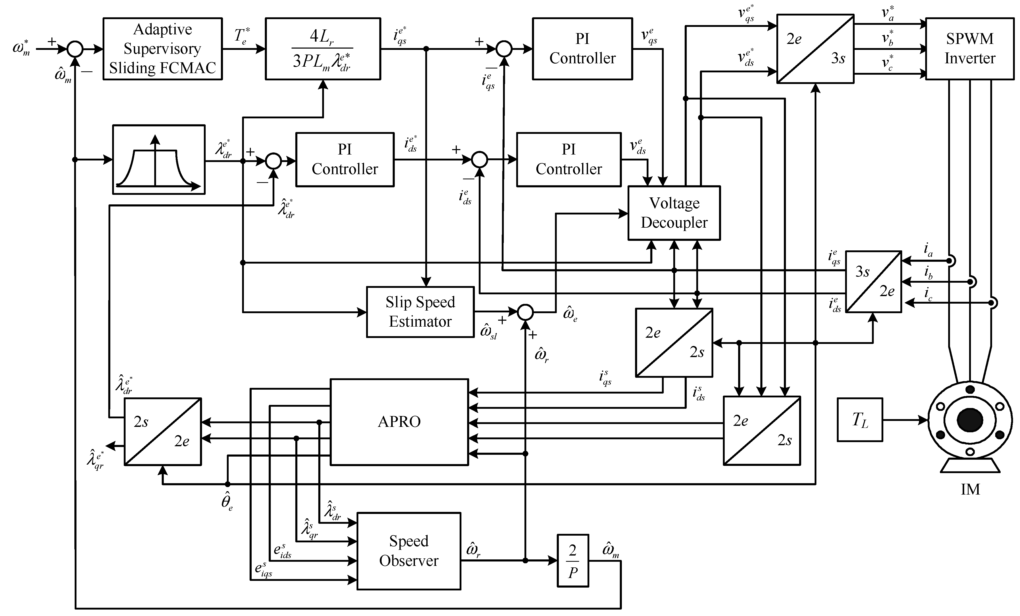
The practicability and robustness of the proposed adaptive supervisory sliding FCMAC were verified by conducting simulations and experiments of the speed controller of the vector-controlled IM system (
Figure 1).
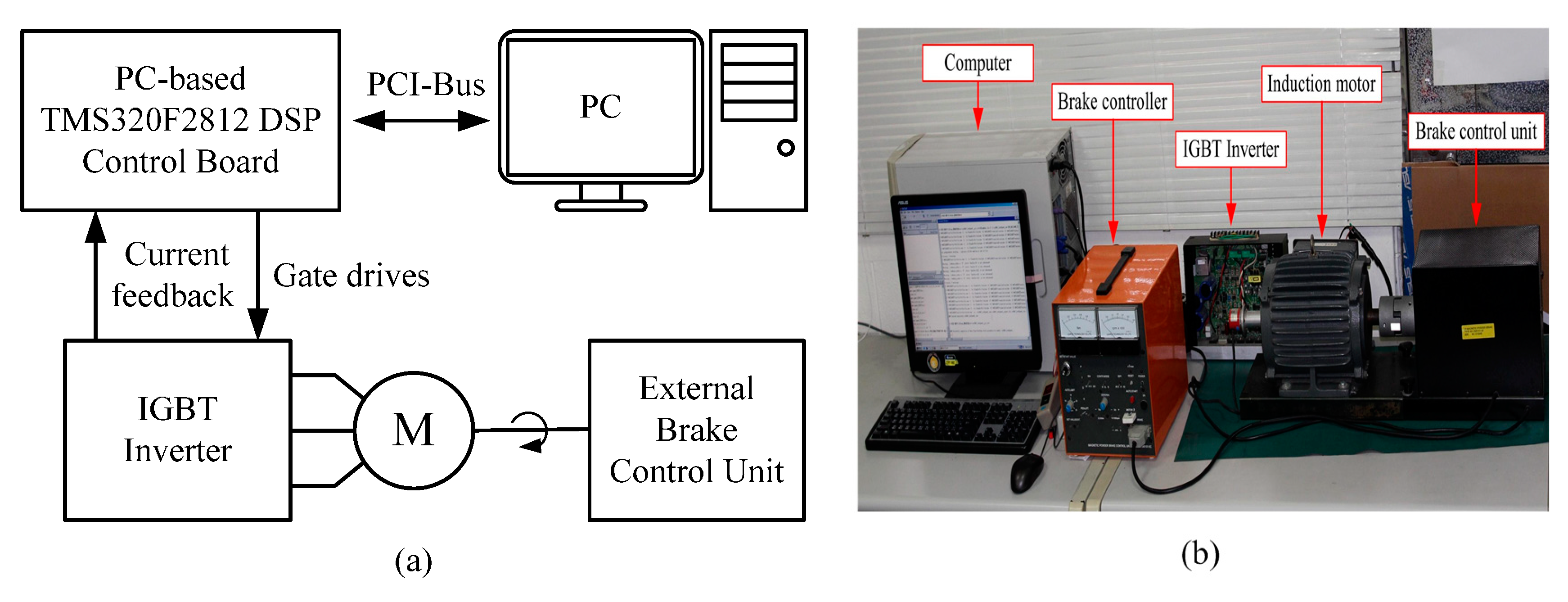
Figure 4 shows a block diagram and photograph of the experimental platform for implementing the proposed system. The experiment was conducted using a PC, a DSP PC-based control board (DSP TMS320F2812 digital control board), insulated-gate bipolar transistor inverter, 2.2-kW IM, and external brake-control unit for applying an external load. For the experimental platform, the DSP control board plugs into the PC and provides a PWM module, A/D and D/A interfaces between PC and the induction motor drive. The control algorithm encompassed the proposed adaptive supervisory sliding FCMAC, vector control loops, APRO, and speed observer, which were designed and implemented using MATLAB/Simulink. The sampling frequency of the experimental platform was 10 kHz. In this study, the speed command was used to perform single-quadrant operation as a spline-shaped curve rather than a step function.
Table 1 shows the IM parameters of the experimental platform.
Table 2 shows the parameters of the proposed adaptive supervisory sliding FCMAC. The adaptive supervisory sliding FCMAC parameters include
h2(ω
m),
h1,
k1,
, and
, which depend on the motor specifications. The other parameters—such as the predefind range of the supervisory controller
DU, adaptation rate of the compensating controller γ, positive constant of the sliding surface
Q, and learning rate of the FCMAC β—were set based on experience. In both the simulation and the experimental study, the sampling time was set to 0.1 ms for the speed control loop and current control loop which was executed over a PC. The switching frequency of the SPWM inverter used in the experiment was 10 kHz, and its rated power was 3 kW. The resolution of the shaft encoder considered in the experimental setup was 2048 counts/rev. In real applications of motor control, due to protection function of inverter module and the limitation of rated motor torque command, the system may be stalled by large control signals in the startup stage. Thus, to make the controller feasible, we modified the control
uS in Equation (20) to
uSM as follows:
where 0 < δ < 1, the δ is set 0.07. The results of the simulations and experiments are discussed in the following section.
4.1. Simulation Results
In order to demonstrate the feasibility of the proposed adaptive supervisory sliding FCMAC control system in induction motor system, simulation results are presented in this section. During motor operation, changing uncertain parameters (e.g., Lr, Rs, Rr, Jm, and Bm) online in the experimental platform is difficult. Thus, MATLAB/Simulink was used to conduct simulations to verify the robustness of the proposed adaptive supervisory sliding FCMAC control system against the Lr, Rs, Rr, Jm, and Bm variations. To reach the aim, several simulations were considered: (1) Induction motor parameters with/without incremental variation; (2) Adaptive supervisory sliding FCMAC control system; (3) Speed tracking using various operations and external load disturbance in the steady state.
The rotor speed command was 1200 rpm with an 8-Nm torque load.
Figure 5,
Figure 6,
Figure 7 and
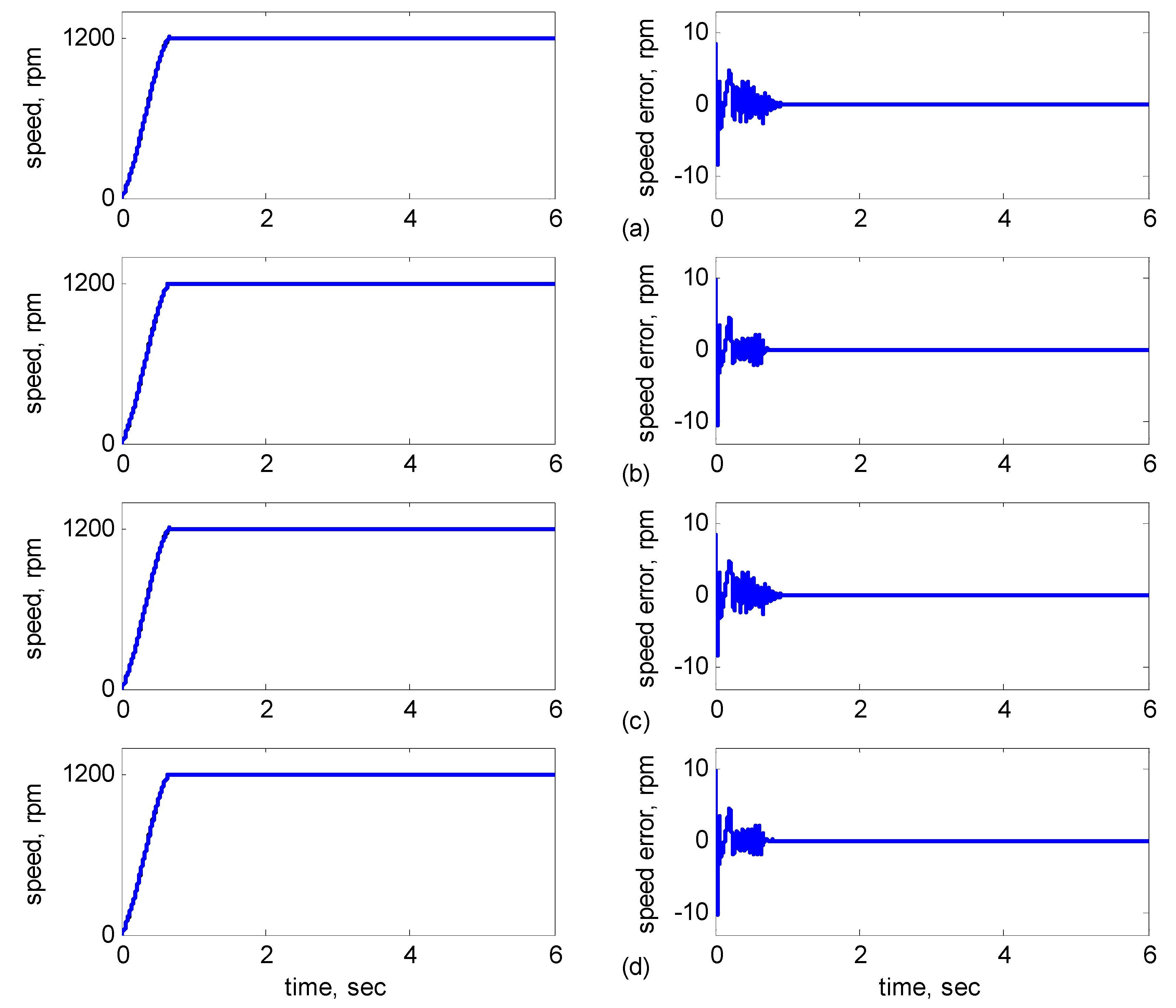
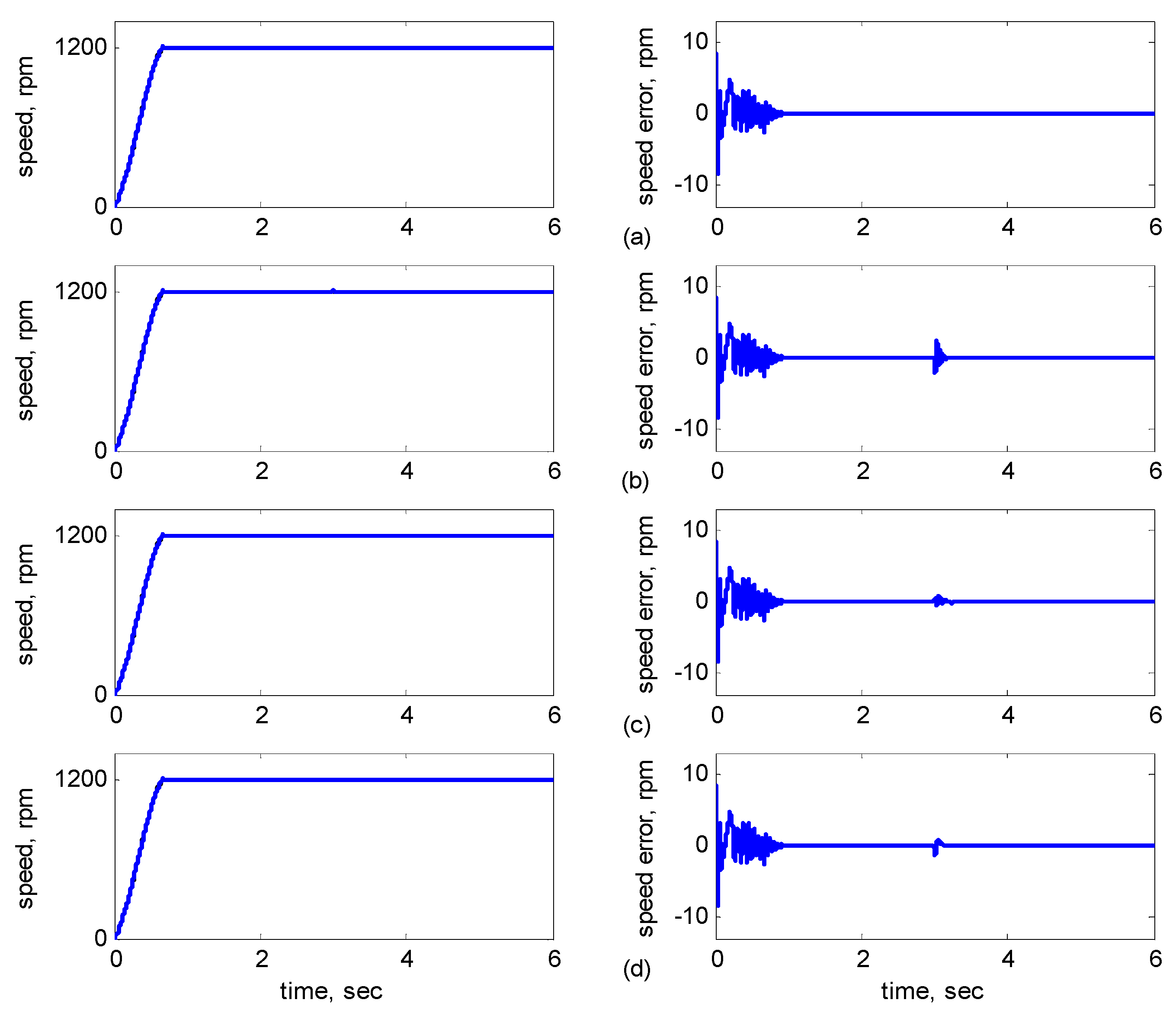
Figure 8 show the simulation results of parameters with/without incremental variation. Each subplot showed the responses of speed (left) and speed error (right).
Figure 5a shows
Jm and
Bm without incremental variations.
Figure 5b shows
Jm with 40% incremental variation.
Figure 5c shows
Bm with 50% incremental variation.
Figure 5d shows
Jm with 40% incremental variation and
Bm with 50% incremental variation.
Figure 5.
Simulation results of speed reference at 1200 rpm: (a) No parameter variation. (b) 40% incremental variation in Jm; (c) 50% incremental variation in Bm; (d) 40% incremental variation in Jm and 50% incremental variation in Bm.
Figure 5.
Simulation results of speed reference at 1200 rpm: (a) No parameter variation. (b) 40% incremental variation in Jm; (c) 50% incremental variation in Bm; (d) 40% incremental variation in Jm and 50% incremental variation in Bm.
Figure 6a shows
Rr and
Rs without variation at 3 s.
Figure 6b shows
Rr with 30% variation at 3 s.
Figure 6c shows
Rs with 30% variation at 3 s and
Figure 6d shows
Rr and
Rs with 30% variation at 3 s.
Figure 7 shows the dynamic responses for
Rr and
Lr with/without incremental variation at 3 s.
Figure 7a shows
Rr and
Lr without variation.
Figure 6.
Simulation results of speed reference at 1200 rpm: (a) No parameter variation. (b) 30% incremental variation in Rr at 3 s; (c) 30% incremental variation in Rs at 3 s; (d) 30% incremental variation at 3 s in both Rr and Rs.
Figure 6.
Simulation results of speed reference at 1200 rpm: (a) No parameter variation. (b) 30% incremental variation in Rr at 3 s; (c) 30% incremental variation in Rs at 3 s; (d) 30% incremental variation at 3 s in both Rr and Rs.
Figure 7.
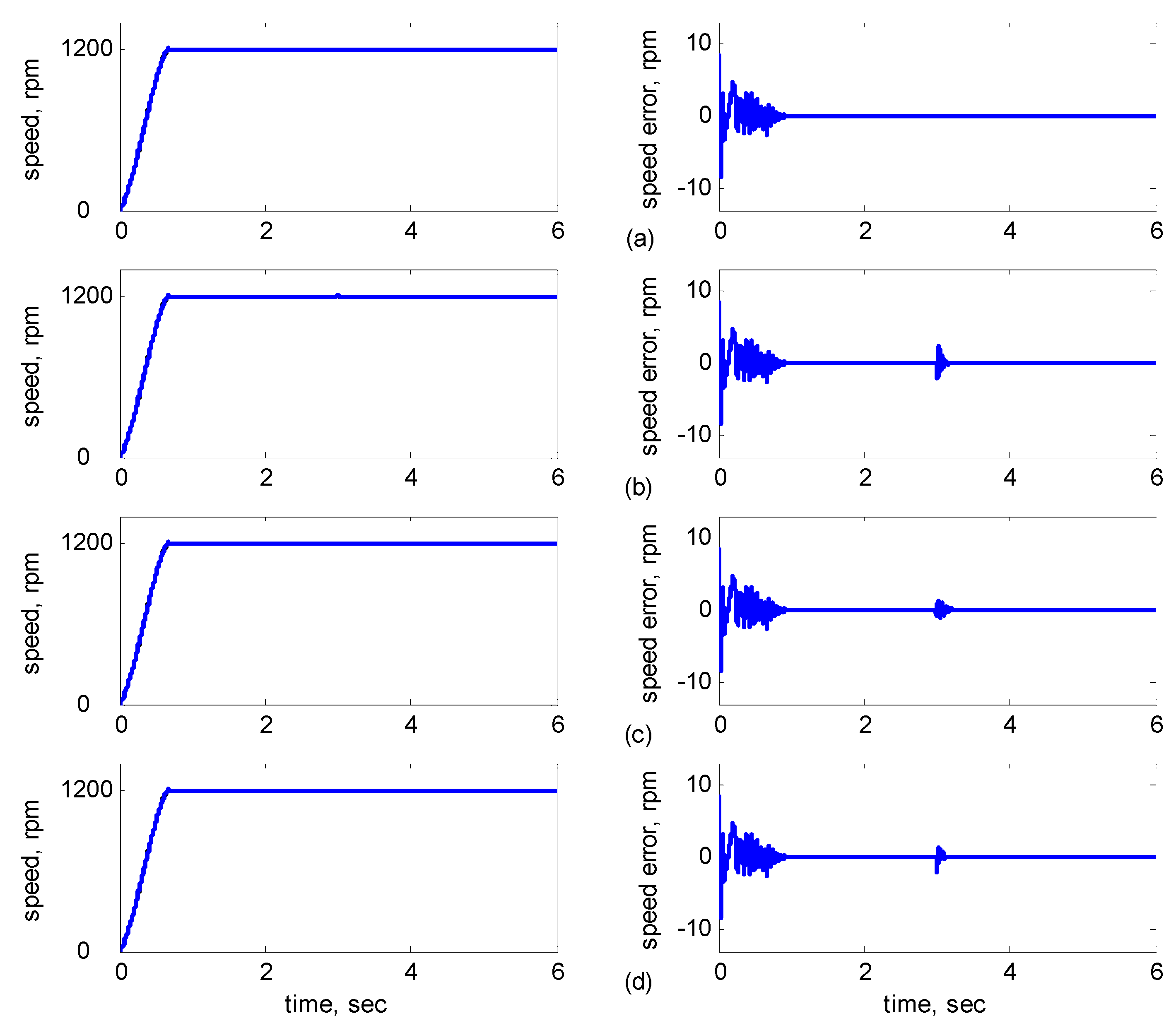
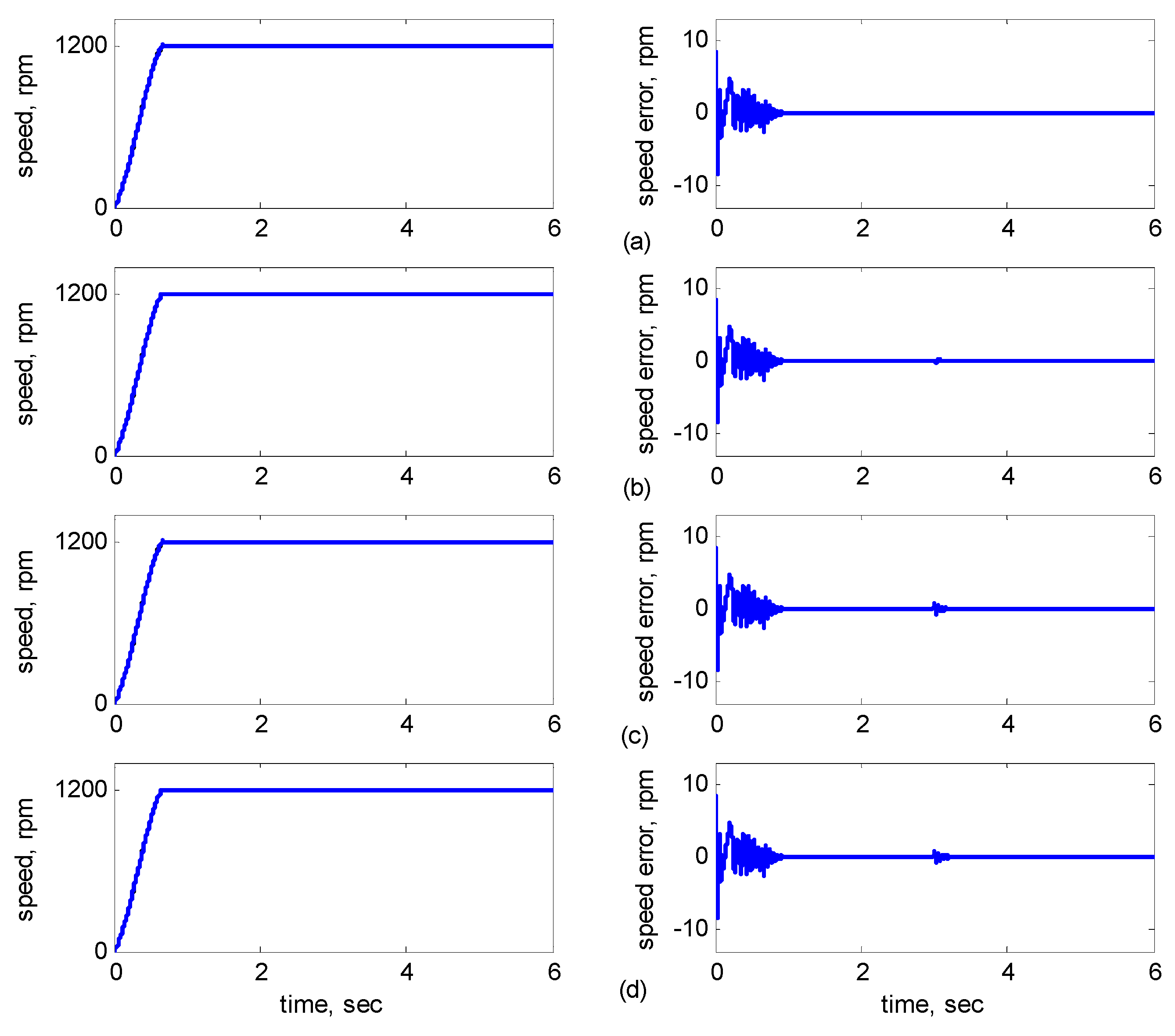
Simulation results of speed reference at 1200 rpm: (a) No parameter variation. (b) 30% incremental variation in Rr at 3 s; (c) 10% incremental variation in Lr at 3 s; (d) 30% incremental variation in Rr and 10% incremental variation in Lr at 3 s.
Figure 7.
Simulation results of speed reference at 1200 rpm: (a) No parameter variation. (b) 30% incremental variation in Rr at 3 s; (c) 10% incremental variation in Lr at 3 s; (d) 30% incremental variation in Rr and 10% incremental variation in Lr at 3 s.
Figure 7b shows
Rr with 30% incremental variation at 3 s.
Figure 7c shows
Lr with 10% incremental variation at 3 s.
Figure 7d shows
Rr with 30% and
Lr with 10% incremental variations at 3 s.
Figure 8 shows the dynamic responses of the adaptive reduced order MRAS for
Rr and
Lr with/without incremental variation at 3 s.
Figure 8a shows
Rr and
Lr without incremental variations.
Figure 8b shows
Rr with 30% incremental variation at 3 s.
Figure 8c shows
Lr with 10% incremental variation at 3 s.
Figure 8d shows
Rr with 30% incremental variation at 3 s and
Lr with 10% incremental variation at 3 s.
Figure 8.
Simulation results of speed reference at 1200 rpm using the adaptive reduced order MRAS: (a) No parameter variation; (b) 30% incremental variation in Rr at 3 s; (c) 10% incremental variation in Lr at 3 s; (d) 30% incremental variation in Rr and 10% incremental variation in Lr at 3 s.
Figure 8.
Simulation results of speed reference at 1200 rpm using the adaptive reduced order MRAS: (a) No parameter variation; (b) 30% incremental variation in Rr at 3 s; (c) 10% incremental variation in Lr at 3 s; (d) 30% incremental variation in Rr and 10% incremental variation in Lr at 3 s.
As shown in
Figure 5a, the maximal speed error was 8.38 rpm, and the speed error of the steady state was in the range of ±0.1 rpm. In
Figure 5b–d, although the maximal speed error was 9.75 rpm when
Jm and
Bm varied, it increased by only 1.37 rpm as compared to that in
Figure 5a, and the speed error of the steady state was also controlled in the range of ±0.12 rpm. In
Figure 6b–d, when
Rr and
Rs varied at 3 s, the increased error range was in ±2 rpm, but in 3 s later, the error was controlled in the range of ±0.12 rpm. In
Figure 7b–d, when
Rr and
Lr varied at 3 s, the increased error range was in ±2 rpm, but in 3 s later, the error was controlled in the range of ±0.12 rpm. In
Figure 8b–d, when
Rr and
Lr varied at 3 s, the increased error range was in ±0.8 rpm, but in 3 s later, the error was controlled in the range of ±0.12 rpm. Therefore, the adaptive supervisory sliding FCMAC was affected only slightly when the mechanical parameters
Lr,
Rr,
Rs,
Jm, and
Bm were varied. Thus, the simulation results indicated the robustness of the proposed adaptive supervisory sliding FCMAC against parameter variations.
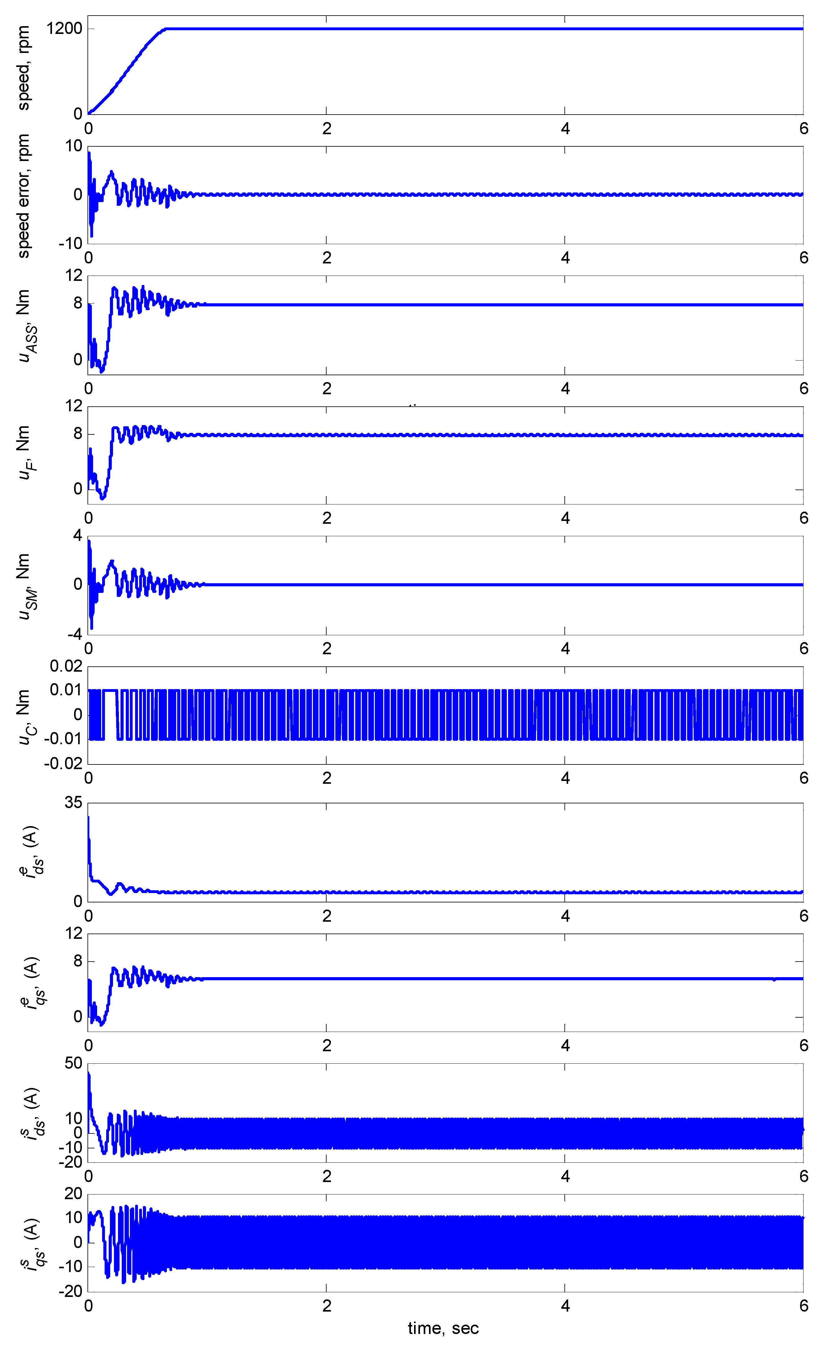
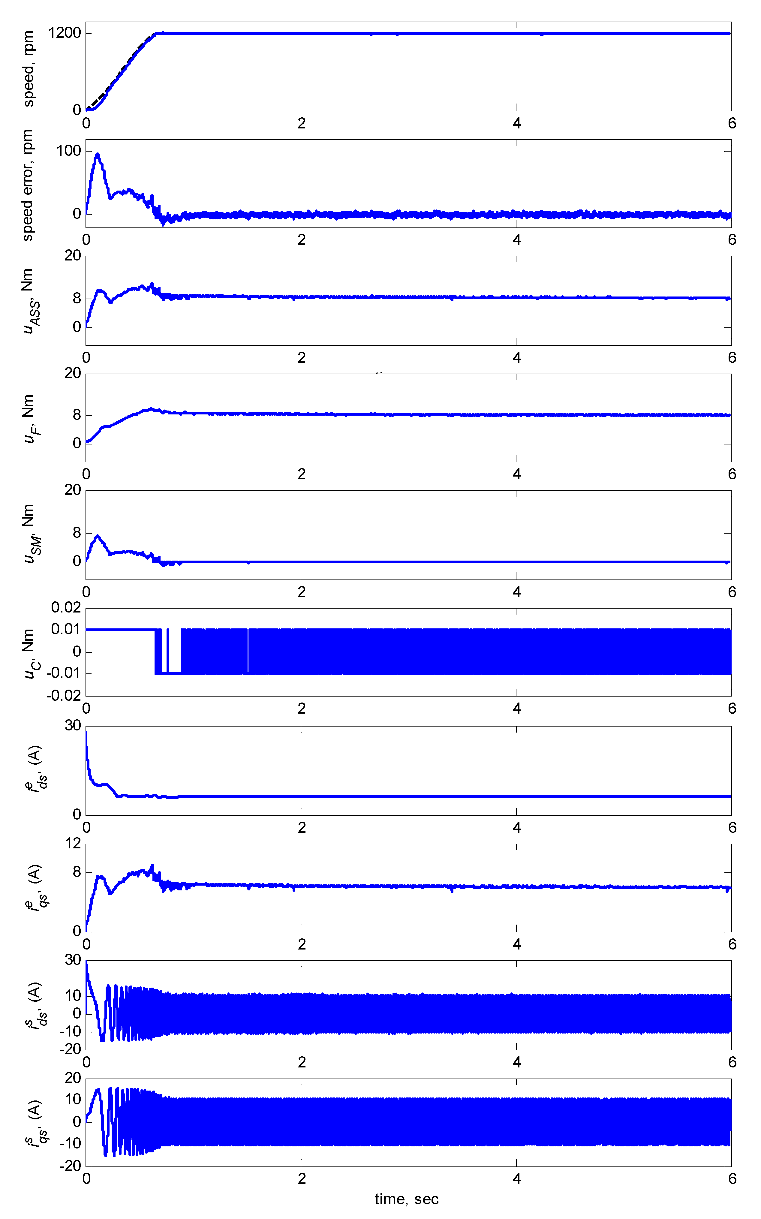
Figure 9 shows the dynamic responses at 1200 rpm with an 8-Nm torque load. The subplots in
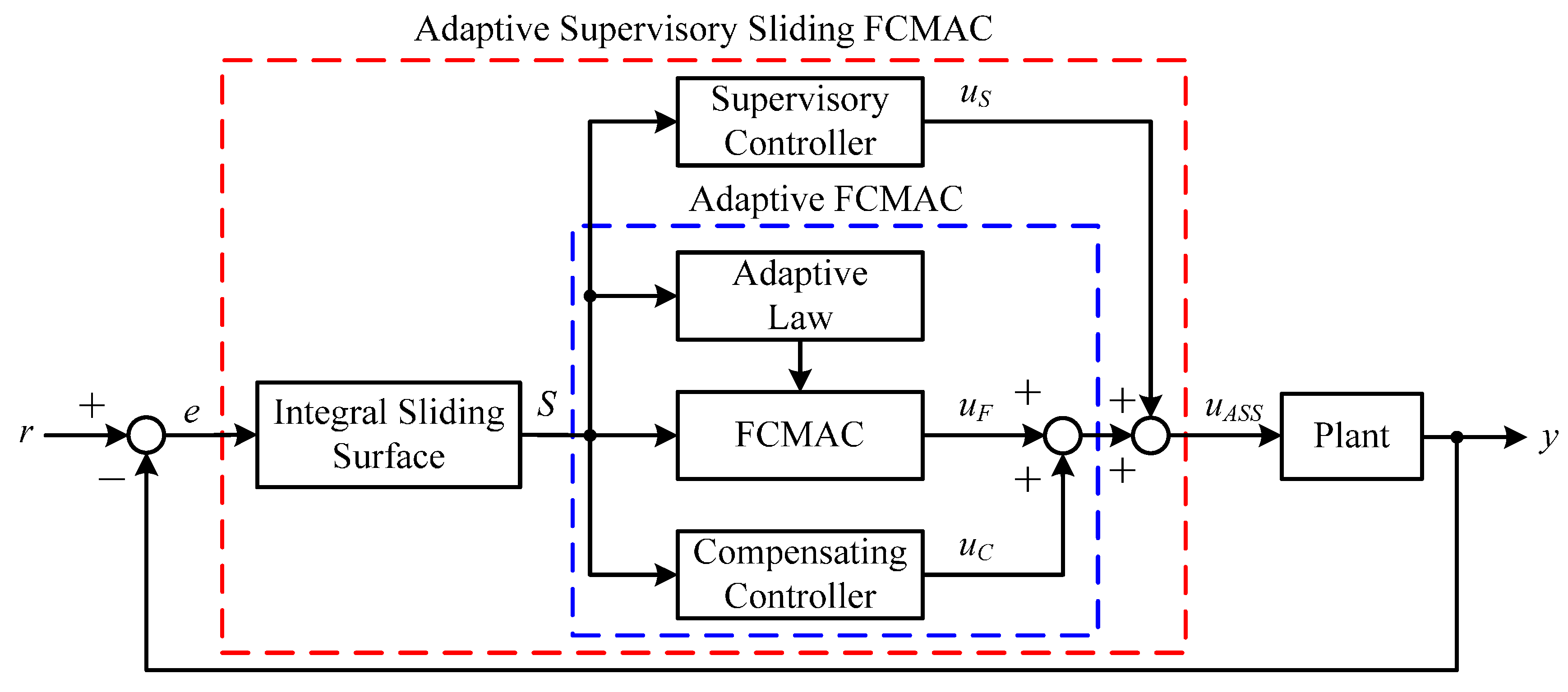
Figure 9 show the responses in speed, speed error, total control law
uASS, FCMAC control
uF, modified supervisory control
uSM, compensating control
uC,
d-q axis stator currents
,
in the stationary reference frames and
d-q axis stator currents
,
in the synchronously rotating reference frames.
Figure 9 indicated that the transient state of the speed response was relatively large when the adaptive FCMAC initiated learning. Thus, the supervisory controller provided a control quantity to improve the transient response until the learning process of the adaptive FCMAC was complete. The transient-state error was less than ±10 rpm and the speed error in the steady state was less than ±0.15 rpm.
Figure 9.
Simulation results of speed response and control efforts of adaptive supervisory sliding FCMAC at speed reference 1200 rpm with 8 Nm torque load.
Figure 9.
Simulation results of speed response and control efforts of adaptive supervisory sliding FCMAC at speed reference 1200 rpm with 8 Nm torque load.
Furthermore, to verify the tracking capability and robustness of the proposed controller against the external load, the adaptive supervisory sliding FCMAC, adaptive sliding FCMAC, and adaptive sliding CMAC were implemented for comparison. The three controllers were derived using the Lyapunov technique, adaptive control theory, and the input signal of these controllers (derived from the integral sliding surface variable). The proposed adaptive sliding CMAC designed based on the conventional CMAC equipped with adaption capability and an integral sliding surface. These controllers were operated and compared at various speeds: 1200 rpm, 2000 rpm, 36 rpm, and ±1200 rpm (four-quadrant speed regulation) with an 8-Nm torque load and an external load disturbance in the steady state of the IM system.
Figure 10,
Figure 11,
Figure 12,
Figure 13 and
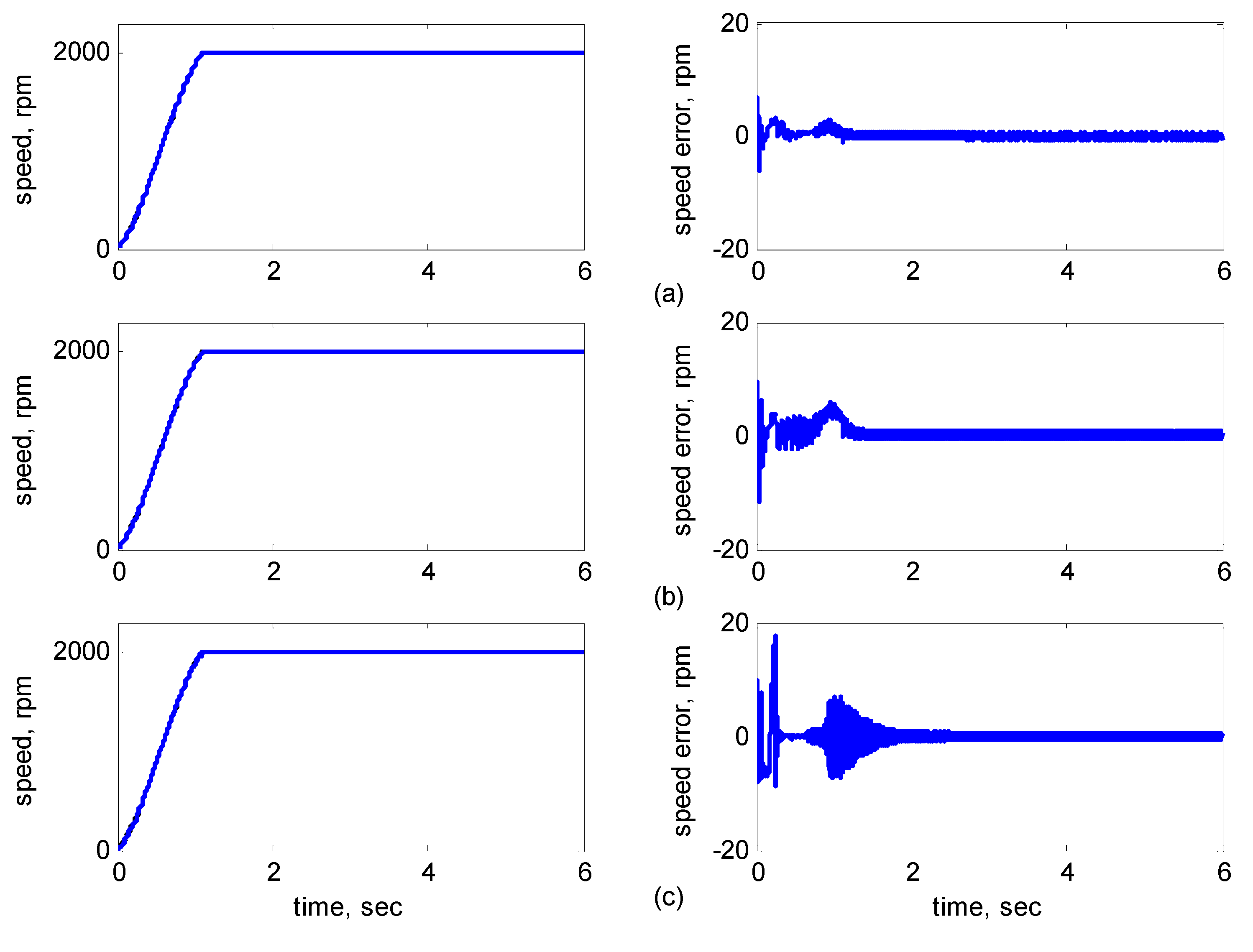
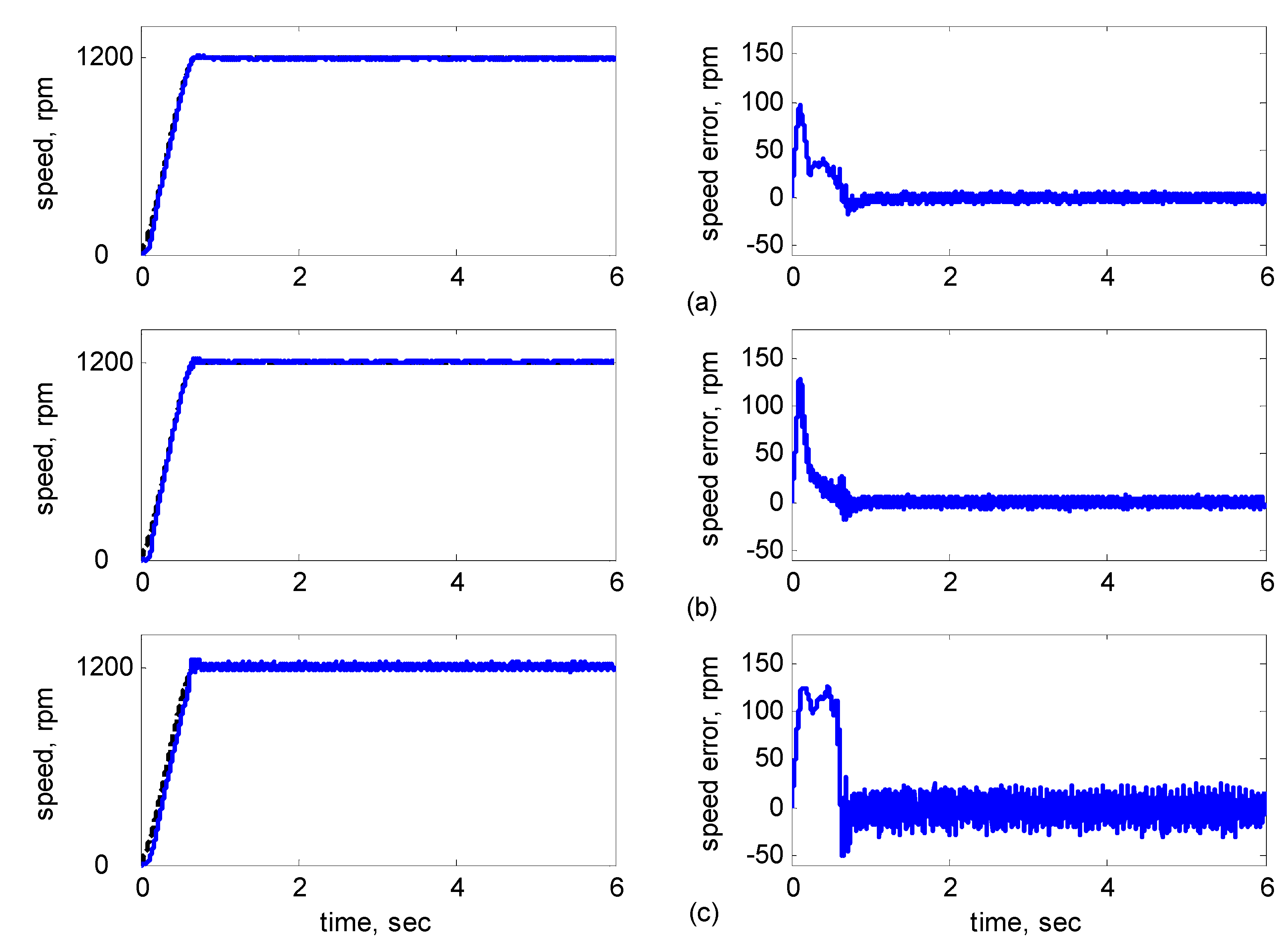
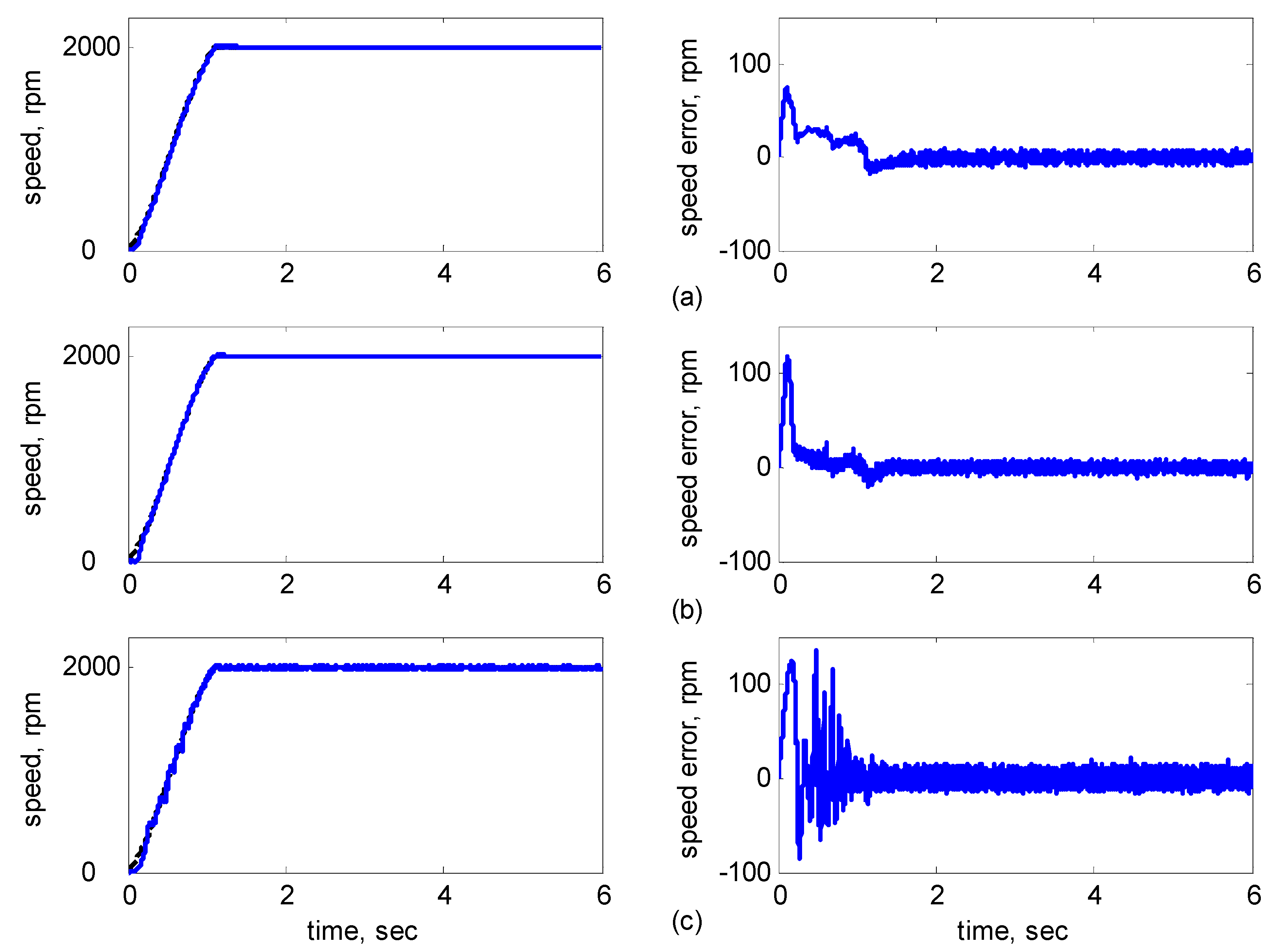
Figure 14 showed the simulation results. Subplot (a) presents the results using adaptive supervisory sliding FCMAC, Subplot (b) presents the results using adaptive sliding FCMAC, and Subplot (c) presents the results using adaptive sliding CMAC. The simulation results for the speed of 1200 rpm and 2000 rpm are shown in
Figure 10 and
Figure 11, respectively. The speed reference (2000 rpm) exceeded the rated motor speed; thus, the motor operated in the flux-weakening region. As shown in
Figure 10a and
Figure 11a, the tracking speed error of the adaptive supervisory sliding FCMAC was less than 0.2 rpm in the steady state. Additionally, the error was also less than that of the other two controllers in the maximal transient state under the same conditions. As shown in
Figure 10b and
Figure 11b, the adaptive sliding FCMAC performed well in the steady state. However, the transient state produced a large speed error and slow convergence because it lacked supervisory control. As shown in
Figure 10c and
Figure 11c, because the values of the association memory were either 0 or 1 when the reference state was excited in the adaptive sliding CMAC, the smoothness of the output was consequently poor and the speed fluctuated widely. Thus, compared with the other intelligent controllers, the adaptive supervisory sliding FCMAC exhibited rapid online learning in the transient state, and the output response was smoother and exhibited faster convergence in the steady state.
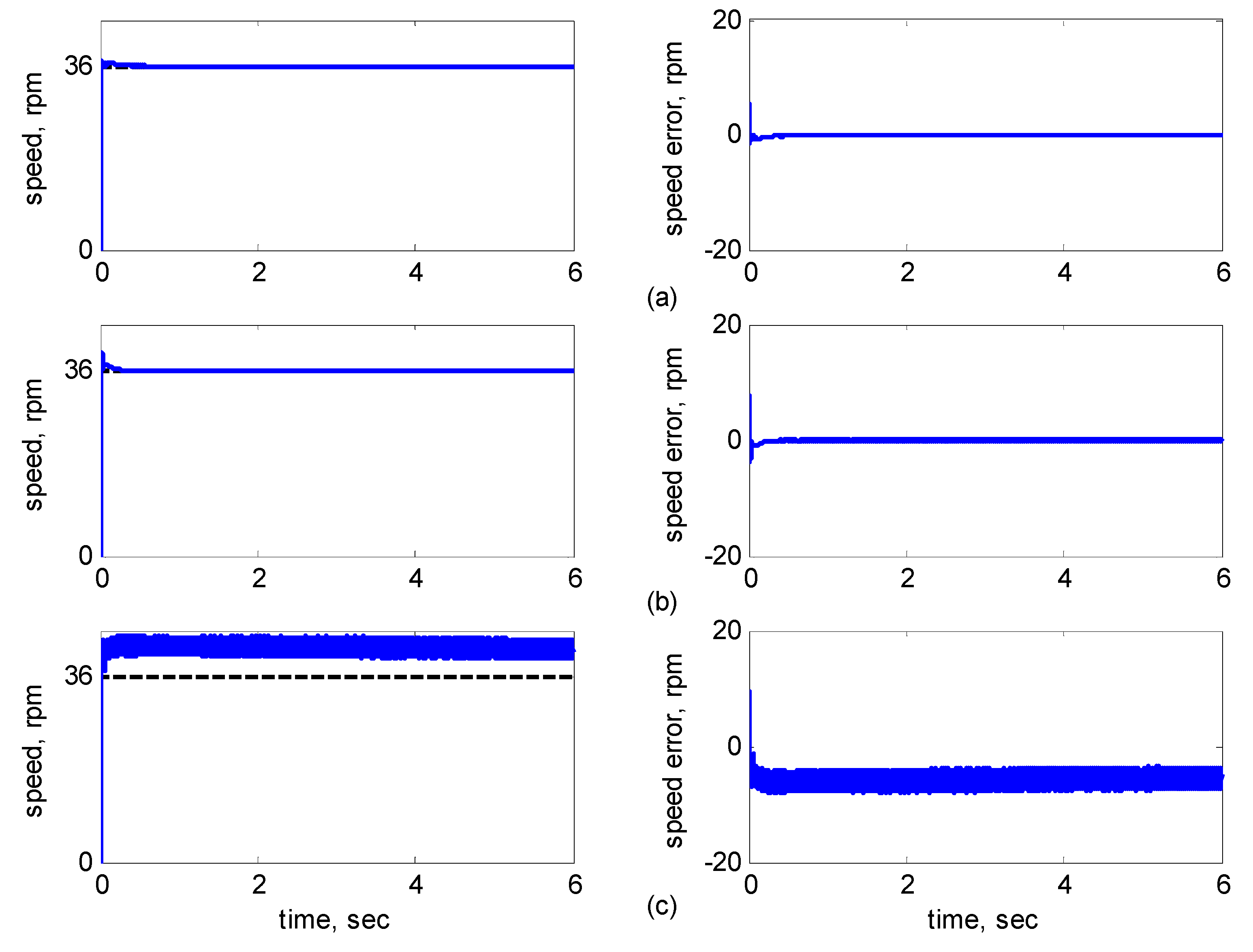
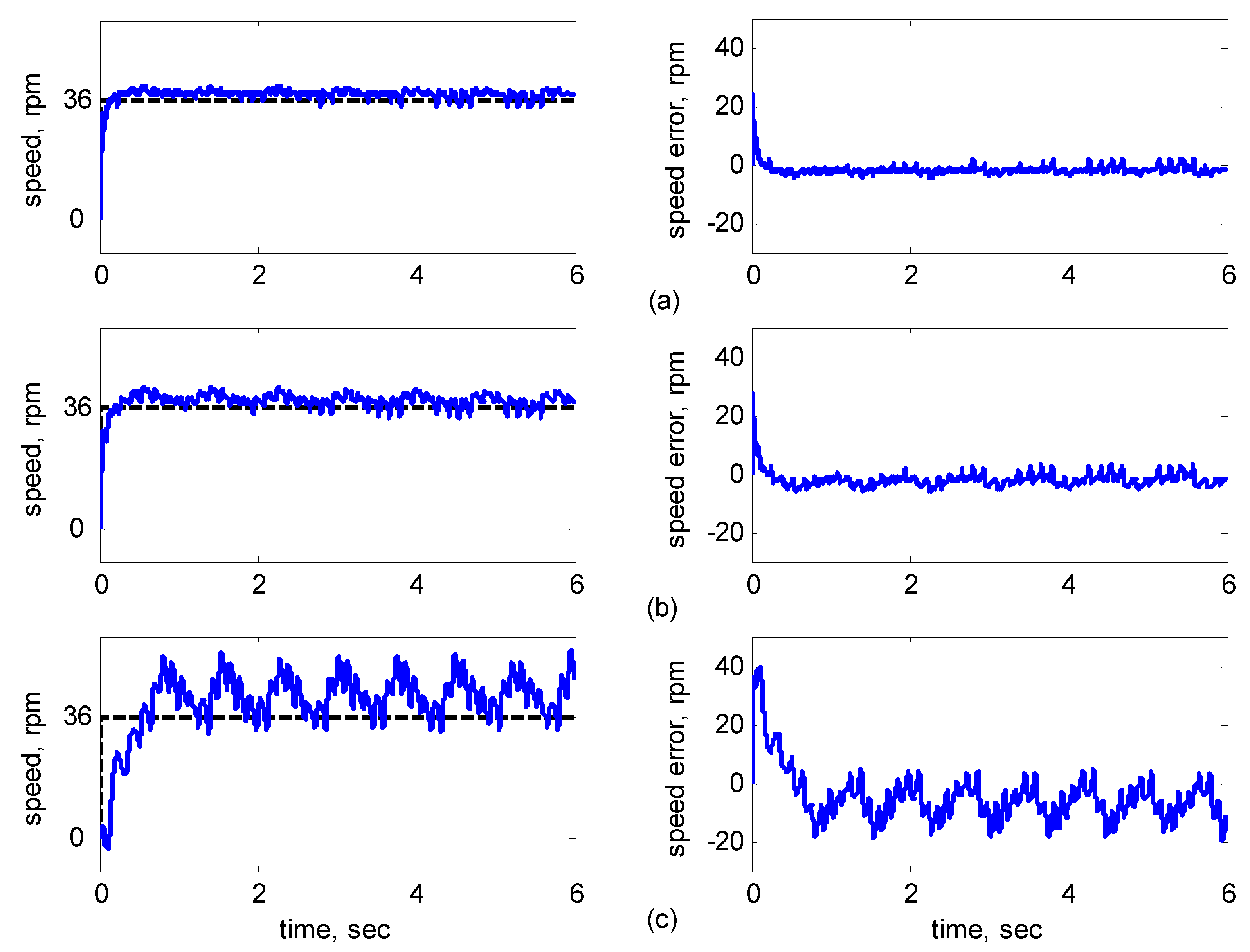
Figure 12 shows the simulation results for the speed of 36 rpm. As shown in
Figure 12a, the maximal speed error of the adaptive supervisory sliding FCMAC was 5.3 rpm in the transient state and the speed error of the steady state was within ±0.004 rpm. As shown in
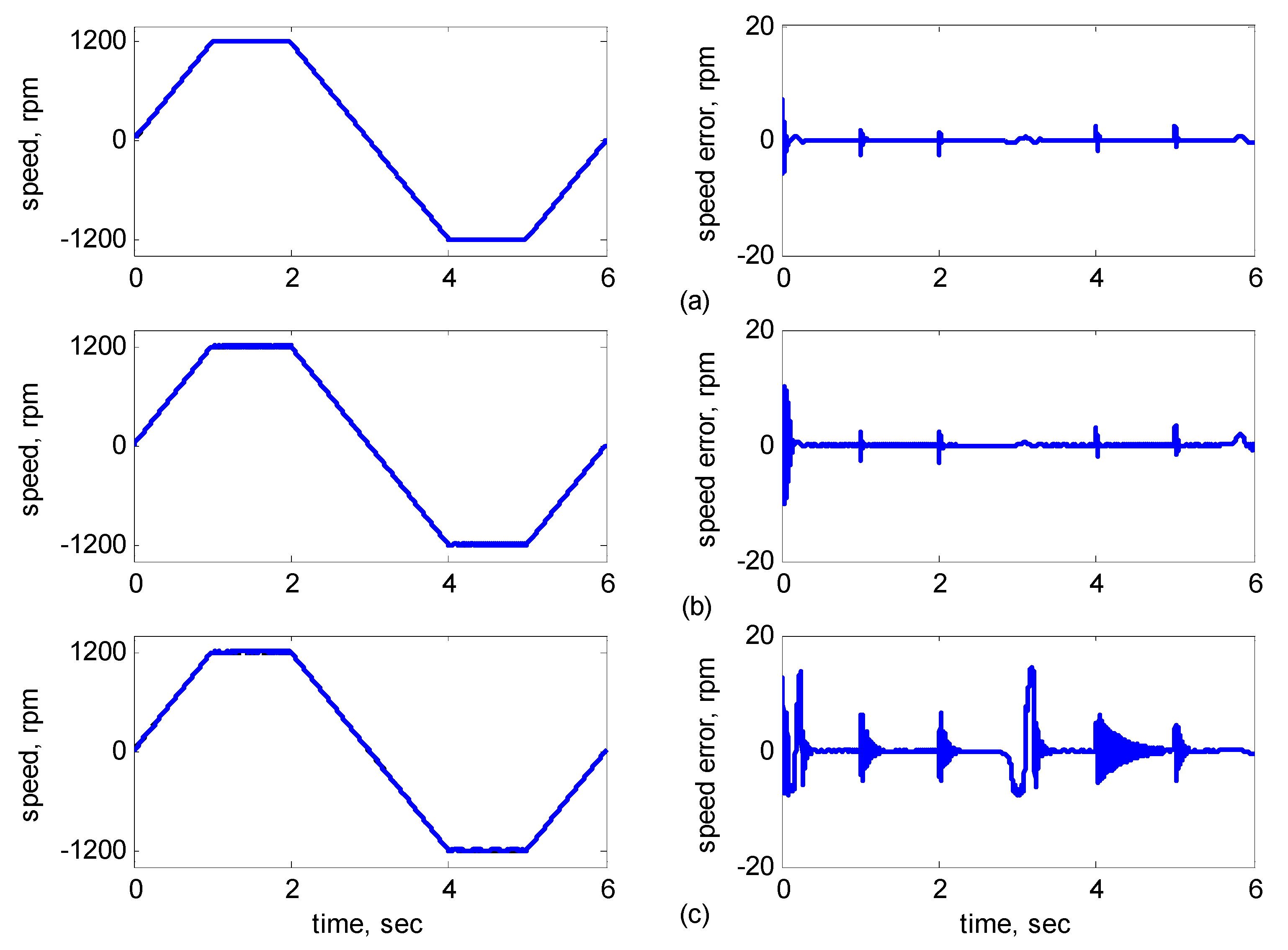
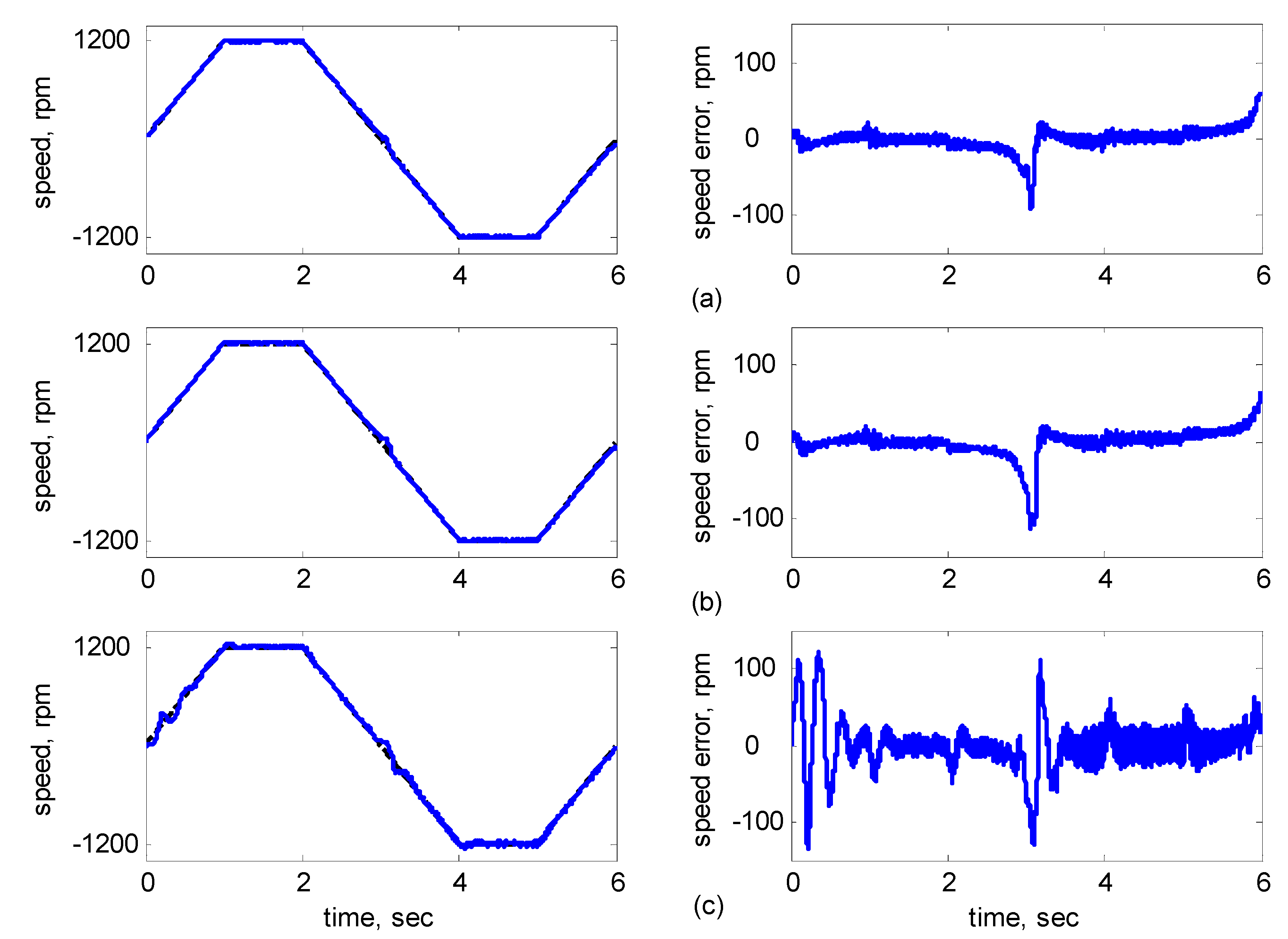
Figure 12b,c, the adaptive sliding FCMAC and the adaptive sliding CMAC were not equipped with supervisory controllers. The speed errors were larger than those of the adaptive supervisory sliding FCMAC in the transient state. However, compared with the responses of adaptive sliding CMAC, the adaptive sliding FCMAC still performed well in the steady state because the FCMAC produced a suitable control effort. For four-quadrant speed regulation (±1200 rpm), when the speed crossed zero, the estimation errors of the stator current increased and caused a large flux estimation error. Consequently, a speed bump occurred at the zero crossing, as shown in
Figure 13. The tracking speed errors of the adaptive supervisory sliding FCMAC and adaptive sliding FCMAC were within 0.5 rpm, and that of the adaptive sliding CMAC was within 15 rpm, as indicated at the zero-crossing point. Therefore, the proposed adaptive supervisory sliding FCMAC outperformed the other two intelligent controllers in
Figure 10,
Figure 11,
Figure 12 and
Figure 13.
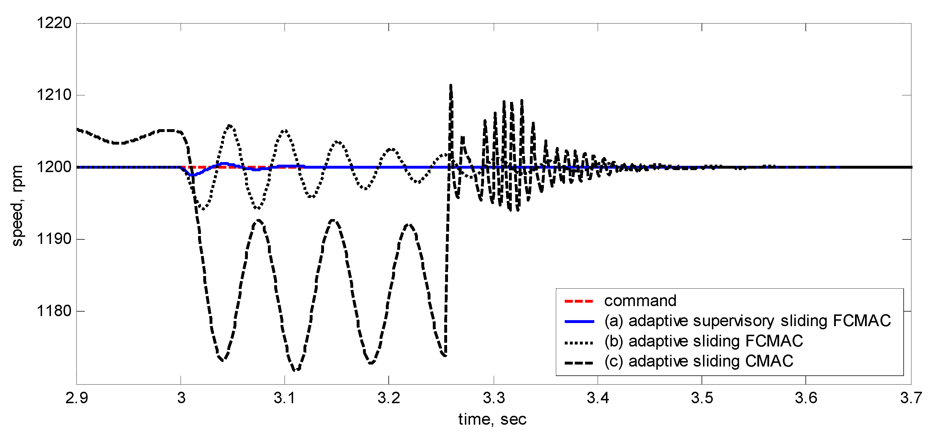
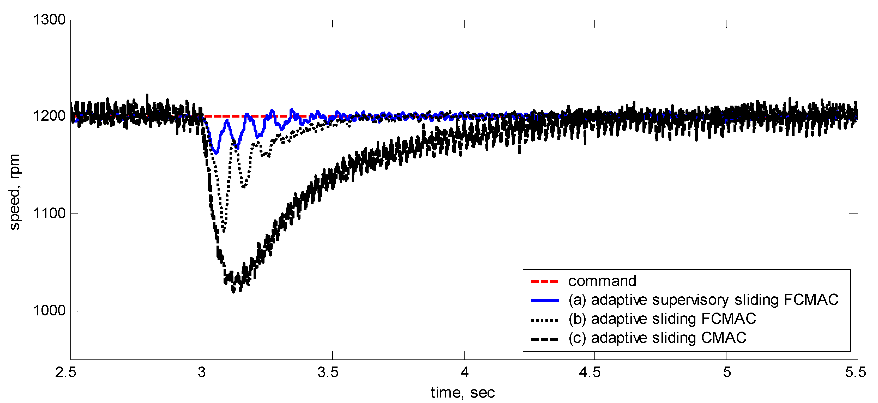
Figure 14 showed the adaptive supervisory sliding FCMAC, adaptive sliding FCMAC, and adaptive sliding CMAC control schemes implemented separately and operated at 1200 rpm without any external load torque for 3 s. A 4-Nm load torque disturbance was applied at exactly 3 s. As shown in
Figure 14, the proposed adaptive supervisory sliding FCMAC recovered the motor speed more quickly than the other two controllers did, because the supervisory controller provided a control quantity to improve the transient response. Thus, the performance of the adaptive supervisory sliding FCMAC was superior to that of the other two controllers after applying torque disturbance.
Figure 10.
Simulation results of speed response: speed (left) and speed error (right) at speed reference 1200 rpm with 8 Nm torque load by using (a) Adaptive supervisory sliding FCMAC; (b) Adaptive sliding FCMAC; (c) Adaptive sliding CMAC.
Figure 10.
Simulation results of speed response: speed (left) and speed error (right) at speed reference 1200 rpm with 8 Nm torque load by using (a) Adaptive supervisory sliding FCMAC; (b) Adaptive sliding FCMAC; (c) Adaptive sliding CMAC.
Figure 11.
Simulation results of speed response: speed (left) and speed error (right) at speed reference 2000 rpm with 8 Nm torque load by using (a) Adaptive supervisory sliding FCMAC; (b) Adaptive sliding FCMAC; (c) Adaptive sliding CMAC.
Figure 11.
Simulation results of speed response: speed (left) and speed error (right) at speed reference 2000 rpm with 8 Nm torque load by using (a) Adaptive supervisory sliding FCMAC; (b) Adaptive sliding FCMAC; (c) Adaptive sliding CMAC.
Figure 12.
Simulation results of speed response: speed (left) and speed error (right) at speed reference 36 rpm with 8 Nm torque load by using (a) Adaptive supervisory sliding FCMAC; (b) Adaptive sliding FCMAC; (c) Adaptive sliding CMAC.
Figure 12.
Simulation results of speed response: speed (left) and speed error (right) at speed reference 36 rpm with 8 Nm torque load by using (a) Adaptive supervisory sliding FCMAC; (b) Adaptive sliding FCMAC; (c) Adaptive sliding CMAC.
Figure 13.
Simulation results of speed response: speed (left) and speed error (right) at speed reference ±1200 rpm with 8 Nm torque load by using (a) Adaptive supervisory sliding FCMAC; (b) Adaptive sliding FCMAC; (c) Adaptive sliding CMAC.
Figure 13.
Simulation results of speed response: speed (left) and speed error (right) at speed reference ±1200 rpm with 8 Nm torque load by using (a) Adaptive supervisory sliding FCMAC; (b) Adaptive sliding FCMAC; (c) Adaptive sliding CMAC.
Figure 14.
Simulation results of speed reference at 1200 rpm with 4 Nm external load disturbance applied at 3 s by using (a) Adaptive supervisory sliding FCMAC; (b) Adaptive sliding FCMAC; (c) Adaptive sliding CMAC.
Figure 14.
Simulation results of speed reference at 1200 rpm with 4 Nm external load disturbance applied at 3 s by using (a) Adaptive supervisory sliding FCMAC; (b) Adaptive sliding FCMAC; (c) Adaptive sliding CMAC.
4.2. Experimental Results
This section presents the experimental results to verify the practicality and robustness of the proposed adaptive supervisory sliding FCMAC control system in real IMs The following experimental cases for the adaptive supervisory sliding FCMAC are discussed:
Case 1: Adaptive supervisory sliding FCMAC control system.
Case 2: Speed tracking using various operations.
Case 3: External load disturbance in the steady state.
Regarding Case 1, the rotor speed was 1200 rpm with an 8-Nm torque load. The subplots in
Figure 15 show the responses in speed, speed error, total control law
uASS, FCMAC control
uF, supervisory control
uS, and compensating control
uC,
d-q axis stator currents
,
in the stationary reference frames and
d-q axis stator currents
,
in the synchronously rotating reference frames. The figure indicates that the transient state of the speed response was relatively large when the adaptive FCMAC initiated learning. Thus, the supervisory controller provided a control quantity to improve the transient response until the learning process was complete. The transient-state error was less than 100 rpm, and the speed error in the steady state was less than 5 rpm.
To verify the tracking capability and robustness of the proposed controller against the external load, the adaptive supervisory sliding FCMAC, adaptive sliding FCMAC, and adaptive sliding CMAC were implemented for comparison in Cases 2 and 3. Regarding Case 2, the three controllers were operated and compared at various speeds (i.e., 1200, 2000, 36, and ±1200 rpm; four-quadrant speed regulation) with an 8-Nm torque load. An external load disturbance in the steady state of the system is presented in Case 3.
Figure 15.
Experimental results of speed response and control efforts of adaptive supervisory sliding FCMAC at speed reference: 1200 rpm with 8 Nm torque load.
Figure 15.
Experimental results of speed response and control efforts of adaptive supervisory sliding FCMAC at speed reference: 1200 rpm with 8 Nm torque load.
Figure 16,
Figure 17,
Figure 18,
Figure 19 and
Figure 20 show the experimental results, where Subplot (a) presents the adaptive supervisory sliding FCMAC results, Subplot (b) depicts the adaptive sliding FCMAC results, and Subplot (c) shows the adaptive sliding CMAC results. The experimental results at 1200 and 2000 rpm are shown in
Figure 16 and
Figure 17, respectively. The speed reference (2000 rpm) was higher than the rated motor speed; thus, the motor operated in the flux-weakening region. As shown in
Figure 16a and
Figure 17a, the tracking speed error of the adaptive supervisory sliding FCMAC was less than 5 rpm in the steady state. Additionally, the error was less than that of the other two controllers in the maximal transient state under identical conditions. As shown in
Figure 16b and
Figure 17b, although the adaptive sliding FCMAC performed effectively in the steady state, the transient state produced a large speed error and slow convergence because no supervisory control was applied.
Figure 16.
Experimental results of speed response: speed (left) and speed error (right) at speed reference 1200 rpm with 8 Nm torque load by using (a) Adaptive supervisory sliding FCMAC; (b) Adaptive sliding FCMAC; (c) Adaptive sliding CMAC.
Figure 16.
Experimental results of speed response: speed (left) and speed error (right) at speed reference 1200 rpm with 8 Nm torque load by using (a) Adaptive supervisory sliding FCMAC; (b) Adaptive sliding FCMAC; (c) Adaptive sliding CMAC.
Figure 17.
Experimental results of speed response: speed (left) and speed error (right) at speed reference 2000 rpm with 8 Nm torque load by using (a) Adaptive supervisory sliding FCMAC; (b) Adaptive sliding FCMAC; (c) Adaptive sliding CMAC.
Figure 17.
Experimental results of speed response: speed (left) and speed error (right) at speed reference 2000 rpm with 8 Nm torque load by using (a) Adaptive supervisory sliding FCMAC; (b) Adaptive sliding FCMAC; (c) Adaptive sliding CMAC.
Figure 18.
Experimental results of speed response: speed (left) and speed error (right) at speed reference 36 rpm with 8 Nm torque load by using (a) Adaptive supervisory sliding FCMAC; (b) Adaptive sliding FCMAC; (c) Adaptive sliding CMAC.
Figure 18.
Experimental results of speed response: speed (left) and speed error (right) at speed reference 36 rpm with 8 Nm torque load by using (a) Adaptive supervisory sliding FCMAC; (b) Adaptive sliding FCMAC; (c) Adaptive sliding CMAC.
Figure 19.
Experimental results of speed response: speed (left) and speed error (right) at speed reference ±1200 rpm with 8 Nm torque load by using (a) Adaptive supervisory sliding FCMAC; (b) Adaptive sliding FCMAC; (c) Adaptive sliding CMAC.
Figure 19.
Experimental results of speed response: speed (left) and speed error (right) at speed reference ±1200 rpm with 8 Nm torque load by using (a) Adaptive supervisory sliding FCMAC; (b) Adaptive sliding FCMAC; (c) Adaptive sliding CMAC.
Figure 20.
Experimental results of speed reference at 1200 rpm with 4 Nm external load disturbance applied at 3 s by using (a) Adaptive supervisory sliding FCMAC; (b) Adaptive sliding FCMAC; (c) Adaptive sliding CMAC.
Figure 20.
Experimental results of speed reference at 1200 rpm with 4 Nm external load disturbance applied at 3 s by using (a) Adaptive supervisory sliding FCMAC; (b) Adaptive sliding FCMAC; (c) Adaptive sliding CMAC.
As indicated in
Figure 16c and
Figure 17c, because the values of the association memory in the adaptive sliding CMAC were either 1 or 0 when the reference state was excited, the smoothness of the output was consequently poor, and the speed fluctuated widely. Thus, compared with the other intelligent controllers, the adaptive supervisory sliding FCMAC exhibited rapid online learning in the transient state, and the output response was smoother and faster convergence was exhibited in the steady state. Thus, the proposed adaptive supervisory sliding FCMAC outperformed the other two intelligent controllers. Vector control of an IM is difficult at low speeds, particularly at 36 rpm. The interior structure of IMs inevitably causes practical dynamics. The structure diminishes the IM’s capacity to produce constant smooth torque output at low speeds, resulting in greater speed-response errors than those occurring at higher speeds.
Figure 18 showed the experimental results at 36 rpm. As shown in
Figure 18a, the maximal speed error of the adaptive supervisory sliding FCMAC was 24.6 rpm in the transient state, and the speed error in the steady state was within ±3 rpm. As shown in
Figure 18b,c, the adaptive sliding FCMAC and adaptive sliding CMAC were not fitted with supervisory controllers. The speed errors were larger than those of the adaptive supervisory sliding FCMAC in the transient state. However, unlike the adaptive sliding CMAC, the adaptive sliding FCMAC maintained an acceptable performance level in the steady state because it produced a suitable control effort. During four-quadrant speed regulation (±1200 rpm), when the speed crossed zero, the estimation errors of the stator current increased, causing a large flux estimation error; consequently, a “speed bump” occurred when the speed was equal to zero (
Figure 19). The tracking speed errors of the adaptive supervisory sliding FCMAC, adaptive sliding FCMAC, and adaptive sliding CMAC were within 95, 110, and 130 rpm, respectively (as indicated at the zero crossing). Thus, the dynamic tracking capability of the proposed adaptive supervisory sliding FCMAC enabled it to outperform the other two controllers.
Figure 20 shows the adaptive supervisory sliding FCMAC, adaptive sliding FCMAC, and adaptive sliding CMAC control schemes implemented separately and operated at 1200 rpm without any external load torque for 3 s. A 4-Nm load torque disturbance was applied at precisely the third second. The figure showed that the proposed adaptive supervisory sliding FCMAC recovered the motor speed faster than did the other two controllers because the supervisory controller provided a control quantity to improve the transient response. Thus, the performance of the adaptive supervisory sliding FCMAC was superior to that of the other two controllers after torque disturbance was applied.
This study used the RMSE as a performance index to evaluate the experimental results of each control scheme under various operating conditions.
Table 3 shows the RMSE results based on 60,000 sampling points over 6 s for Case 2. The RMSE can be expressed as:
where
e(
k) is the tracking error and
L denotes the number of sampling points.
Table 3 showed that the RMSE value of the adaptive supervisory sliding FCMAC was far lower than that of the other two control schemes during various speed operations. The experimental results indicated that the proposed adaptive supervisory sliding FCMAC outperformed the other two controllers under all operating conditions.
Table 3.
The statistics of the RMSE results.
Table 3.
The statistics of the RMSE results.
| Speed Reference | 1200 rpm | 2000 rpm | 36 rpm | ±1200 rpm |
|---|
| Control Scheme | |
|---|
| Adaptive supervisory sliding FCMAC | 4.78 | 4.3 | 0.78 | 4.7 |
| Adaptive sliding FCMAC | 5.24 | 4.56 | 1.04 | 5.99 |
| Adaptive sliding CMAC | 10.9 | 7.23 | 3.33 | 10.41 |


