Analytical Study of the Propagation of Fast Longitudinal Modes along wz-BN/AlN Thin Acoustic Waveguides


Abstract
: The propagation of the fundamental symmetric Lamb mode S0 along wz-BN/AlN thin composite plates suitable for telecommunication and sensing applications is studied. The investigation of the acoustic field profile across the plate thickness revealed the presence of modes having longitudinal polarization, the Anisimkin Jr. plate modes (AMs), travelling at a phase velocity close to that of the wz-BN longitudinal bulk acoustic wave propagating in the same direction. The study of the S0 mode phase velocity and coupling coefficient (K2) dispersion curves, for different electrical boundary conditions, has shown that eight different coupling configurations are allowable that exhibit a K2 as high as about 4% and very high phase velocity (up to about 16,700 m/s). The effect of the thickness and material type of the metal floating electrode on the K2 dispersion curves has also been investigated, specifically addressing the design of an enhanced coupling device. The gravimetric sensitivity of the BN/AlN-based acoustic waveguides was then calculated for both the AMs and elliptically polarized S0 modes; the AM-based sensor velocity and attenuation shifts due to the viscosity of a surrounding liquid was theoretically predicted. The performed investigation suggests that wz-BN/AlN is a very promising substrate material suitable for developing GHz band devices with enhanced electroacoustic coupling efficiency and suitable for application in telecommunications and sensing fields.1. Introduction
Electroacoustic devices based on the propagation of surface and bulk acoustic waves (SAW and BAW) are known for their wide range of applications in chemical, biological and physical sensing fields. When these devices are required to operate in a liquid environment, they must involve the propagation of specific types of acoustic waves that do not radiate energy into the liquid. Love waves, surface transverse waves (STW), shear horizontal acoustic plate modes (SHAPM) and shear horizontal SAW (SHSAW) are examples of acoustic waves whose shear horizontal polarization ensures no coupling between the liquid and the elastic propagating medium. Waves with elliptical polarization, such as the Rayleigh-like waves, are impractical for use in liquid environments as a consequence of the high energy loss in the liquid, both by radiating compressional waves into the fluid and due to frictional losses in the fluid. The fundamental antisymmetric Lamb mode, A0, while being elliptically polarized, can travel along thin plates that are in contact with a liquid for a limited plate thickness range corresponding to mode velocities lower than the compressional velocity vliq of the surrounding liquid medium. The fundamental symmetric Lamb mode, S0, as well as the higher order symmetrical and antisymmetrical modes are elliptically polarized and have a velocity higher than that of the surrounding liquid medium, and thus, they are not suitable for sensing applications in liquids, except for some special cases. These cases include the linearly-polarized modes, such as the longitudinally-polarized Anisimkin Jr. modes (AMs), with a dominant longitudinal displacement component U1 with a constant amplitude along the whole depth of the plate, the shear components, U2 and U3, being at least 10-times less than U1 at any plate depth. AMs were first discovered in quartz plates [1] and then in LiNbO3, Te [2], LiTaO3, Ba2NaNb5O15, KH2PO4, Li2B4O7, TeO2, PbMoO4, KH2PO4 and ZnO [3,4] and, recently, in GaPO4 [5]. The AMs, while having a phase velocity close to that of the longitudinal bulk acoustic wave (LBAW) traveling in the same direction, can be suitable for the development of high-frequency electroacoustic devices if implemented on fast materials, such as BN and AlN. Boron nitride (BN) is a group III–V compound semiconductor, and wurtzite (wz-BN) and cubic BN (zb-BN) are two representative crystal structures. The former is chemically inert and thermally stable and has been widely used as an electrical insulator and heat-resistant material. The latter, which is a super-hard material with properties similar to diamond, including chemical inertness, shows excellent properties, such as a high melting temperature, high thermal conductivity and chemical stability. zb- and wz-BN films are currently grown by sputtering (DC or RF) and by hollow cathode arc evaporation apparatus on Si(001) and Si(111), respectively [6–9]. AlN is the fastest piezoelectric material among those that can be grown in thin film form: compared to ZnO, for example, AlN films show higher SAW velocity (5607 m/s, as opposed to 2682 m/s), higher hardness (17.7 GPa, as opposed to 4.7 GPa) and thermal conductivity (2.8 W·cm−1·°C−1, as opposed to 0.6 W·cm−1·°C−1) and a slightly lower electroacoustic coupling coefficient K2 (0.3%, as opposed to 0.97%). The AlN resistance to high temperature and to caustic chemicals make it the ideal candidate for the development of electroacoustic devices able to survive in harsh environment. The present paper investigates the acoustic wave propagation along wz-BN/AlN thin composite plates that are suitable for the development of high-frequency electroacoustic devices for telecommunications and sensing applications [10].
2. SAW and BAW Propagation along BN and AlN
The SAW phase velocity in zb-BN is highly affected by the material anisotropy, as well as the BAW; on the contrary, wz-BN and c-AlN are isotropic in the c-plane, and hence, both the SAW and BAW velocities are unaffected by the propagation direction in this plane. The SAW propagating along the AlN and wz-BN c-plane is a Rayleigh-type wave that has only two non-null rapidly-damped displacement components, U1 and U3, lying in the sagittal plane. The K2 of the Rayleigh-like waves, as well as the velocities of the SAW and BAW propagating along the <100> direction of AlN and BN crystals are listed in Table 1. The acoustic wave velocity calculations were performed by using MATLAB software in the lossless approximation; the BN and AlN material data were deduced by [11,12].
As can be seen from Table 1, wz-BN is a weakly piezoelectric material showing very high SAW and BAW velocities, which make this material attractive for the development of high-frequency electro-acoustic devices.
3. Acoustic Wave Propagation along BN and BN/AlN Plates
3.1. BN Plates
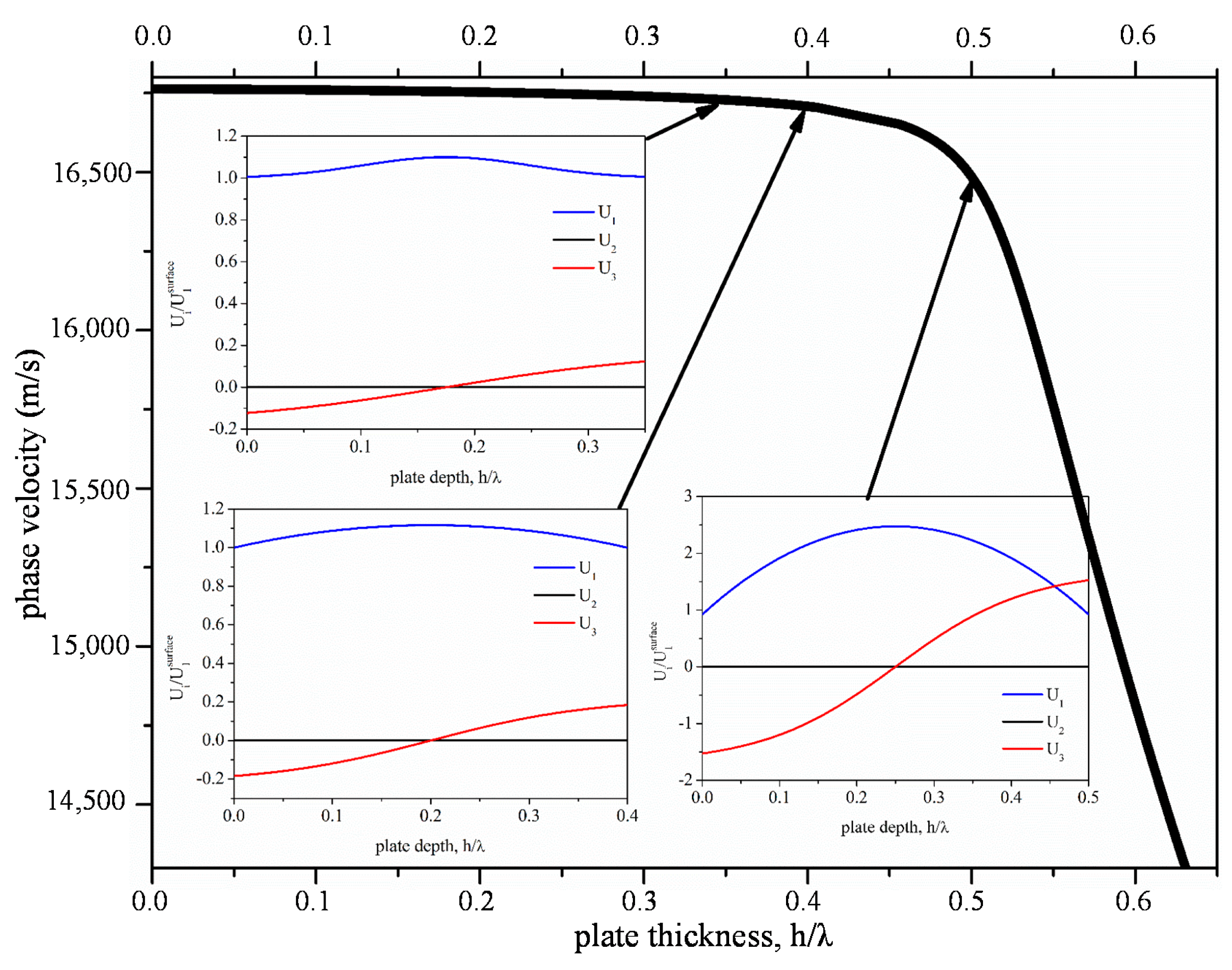
Figure 1 shows the phase velocity of the fundamental symmetric Lamb mode, S0, vs. the bare wz-BN plate thickness normalized to the wavelength, hBN/λ. The dispersion curve is characterized by a low dispersion region, where the velocity is almost constant and very close to vLBAW, followed by a drop in velocity. In the flat dispersion region, the S0 mode transforms first to the AM counterpart with constant and dominant longitudinal displacement component U1, while U2 = 0 and U3 ≤ 10%·U1. With increasing the plate thickness, the mode transforms to the quasi-longitudinal (QL) counterpart: the longitudinal displacement component is no longer constant through the thickness of the plate, but it is still dominant over the other two components (U2 = 0 and U3 ≪ U1). For higher plate thicknesses, when the S0 mode velocity approaches the shear horizontal BAW velocity, the shear horizontal component U2 largely dominates U1 and U3, but this wave is electrically uncoupled. The insets of Figure 1 show the three particle displacement components, U1, U2 and U3, vs. the BN plate depth, for three different plate thicknesses, hBN/λ = 0.35, 0.4 and 0.5. At hBN/λ = 0.35, the QL mode (QLM) propagates, while with increasing hBN/λ, the U3 contribution slowly increases and becomes comparable to that of U1, while the displacement component U2 remains equal to zero. For hBN/λ > 1, the mode begins to act as a Rayleigh wave propagating on the surfaces of the plate.
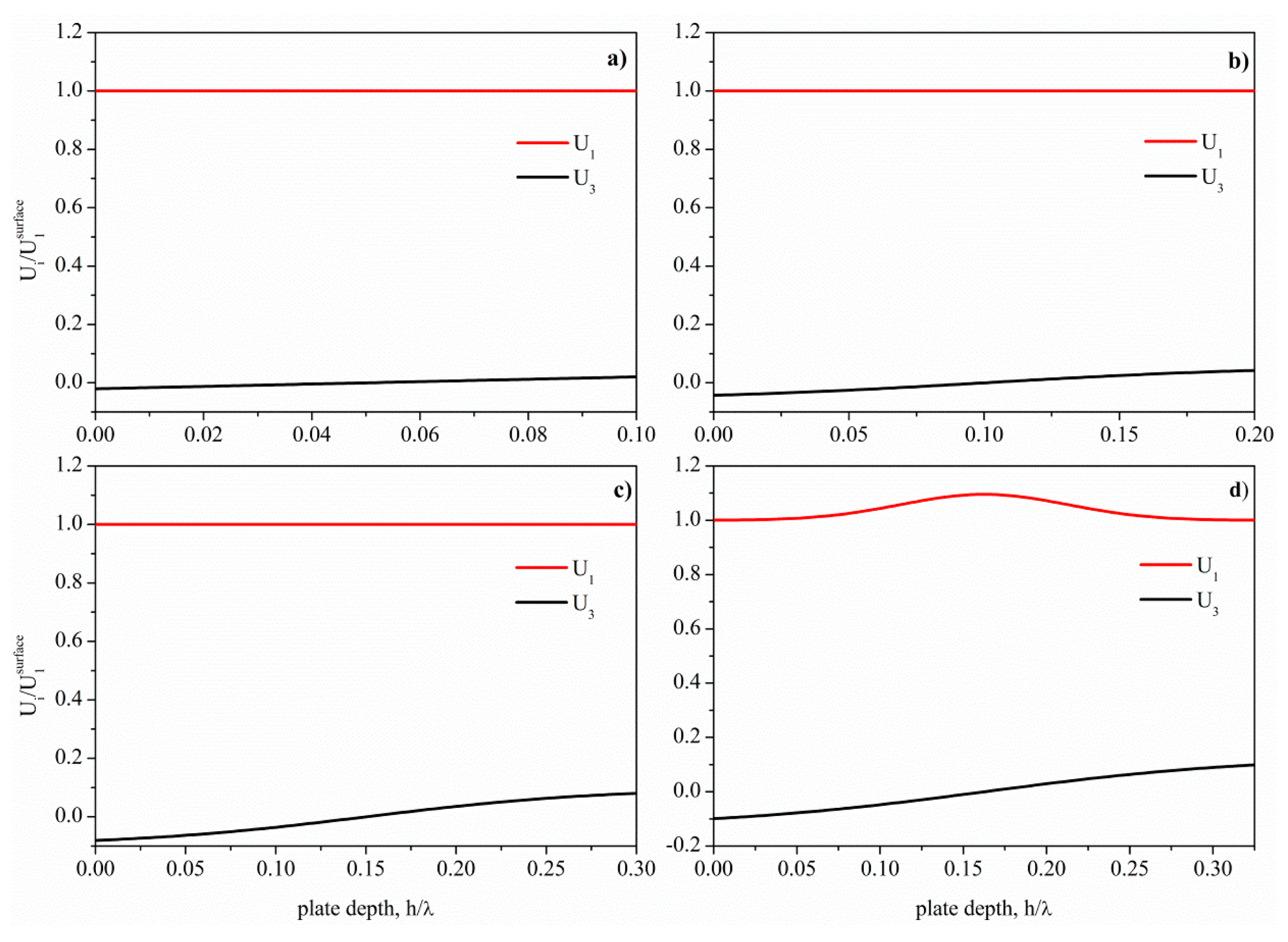
The theoretical investigation of the mode field profile across the depth of the wz-BN thin bare plate revealed that the AMs propagate in the limited hBN/λ range up to 0.325, with velocities from 16,760 (hBN/λ = 0.1) to 16,735 m/s (hBN/λ = 0.325). Figure 2 shows the depth profile of the AMs for four BN plate thicknesses: the displacement components U1 and U3 are normalized to the U1 value at the surface. The shear horizontal component U2 is not shown in Figure 2, as it is null. For hBN/λ > 0.325, U3 increases, and U1 is no longer constant through the plate depth; the acoustic field profile of the S0 mode changes according to the behavior shown in the insets of Figure 1.
Unfortunately, the piezoelectricity of BN is weak, thus BN-based electroacoustic devices are impractical without the addition of a thin piezoelectric film, such as AlN, whose technology is well established nowadays.
3.2. BN/AlN Composite Plates
The BN/AlN acoustic waveguide that we want to investigate consists of an acoustically thin suspended membrane that can be fabricated by a conventional bulk micromachining technique of a specifically orientated Si wafer. In addition to the Si substrate, the wz-BN thin film is to be used as an etch stop and to form the underlying membrane of the device. A piezoelectric AlN film is deposited on the BN layer, followed by a metallic layer (typically Al, Mo or Pt) on which the interdigital transducers (IDTs) are photolithographically patterned to generate and detect the propagating acoustic waves. The acoustic waves are generated by the application of an alternating voltage signal to the IDTs patterned on the piezoelectric substrate; the IDTs geometry dictates the wavelength of the excited wave, (λ = IDTs' period length), and the phase velocity of the wave dictates the device frequency, f = v/λ. The fabrication procedure of the BN/AlN-based acoustic waveguide is compatible with the semiconductor processing techniques, thus offering the advantage of providing the monolithic integration of the device with the signal processing electronics.
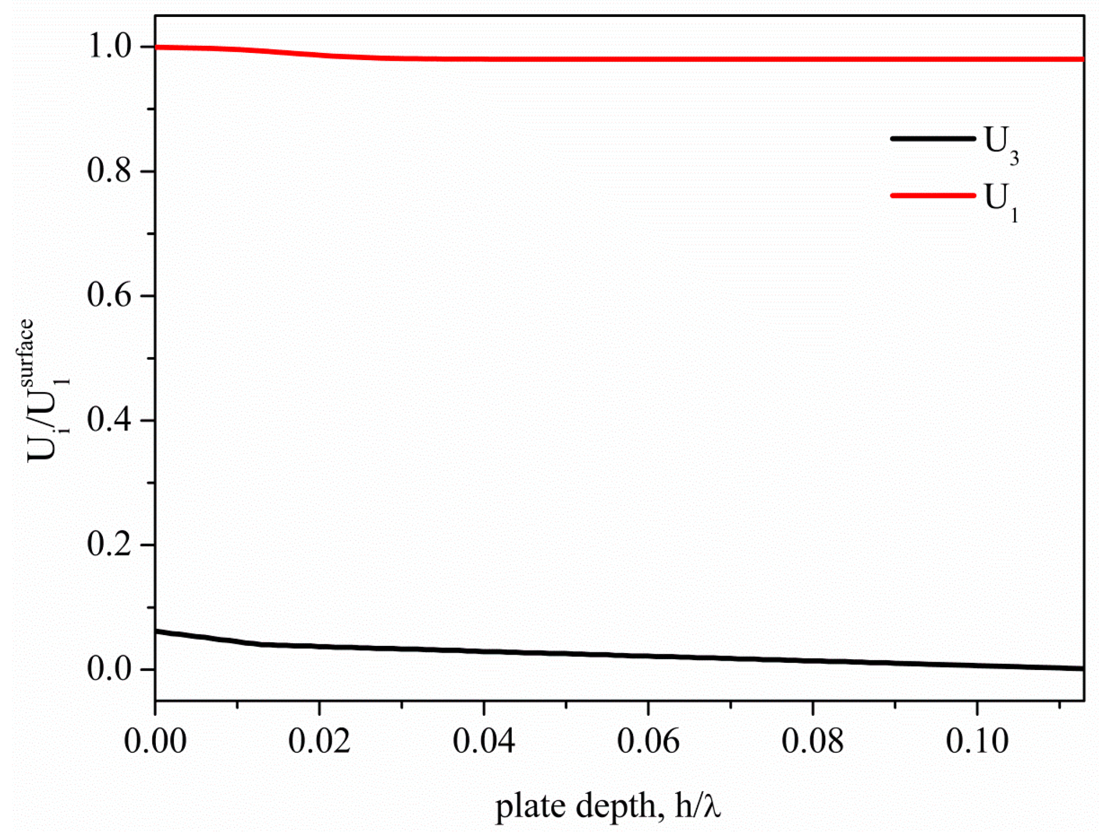
AMs propagate along BN/AlN composite plates only for very small AlN thicknesses that depend on the BN underlayer thickness. As an example, Figure 3 shows the AM field profile in the BN/AlN plate for hBN/λ = 0.1 and hAlN/λ = 0.013, 0.013 being the maximum AlN thickness that still allows the propagation of the AM through the composite plate with hBN/λ = 0.1. As can be seen, the presence of the AlN layer weakly affects the AM depth profile, while for hAlN/λ > 0.013, the AM converts into a QLM. For hAlN/λ < 0.013, the AM field profile along the plate depth is unaffected by the presence of the AlN layer, being U1 = 1 across the plate depth. For hBN/λ = 0.2, 0.3 and 0.325, the maximum hAlN/λ values compatible with the AMs propagation along the BN/AlN composite plates are 0.01, 0.004 and 0.001, respectively.
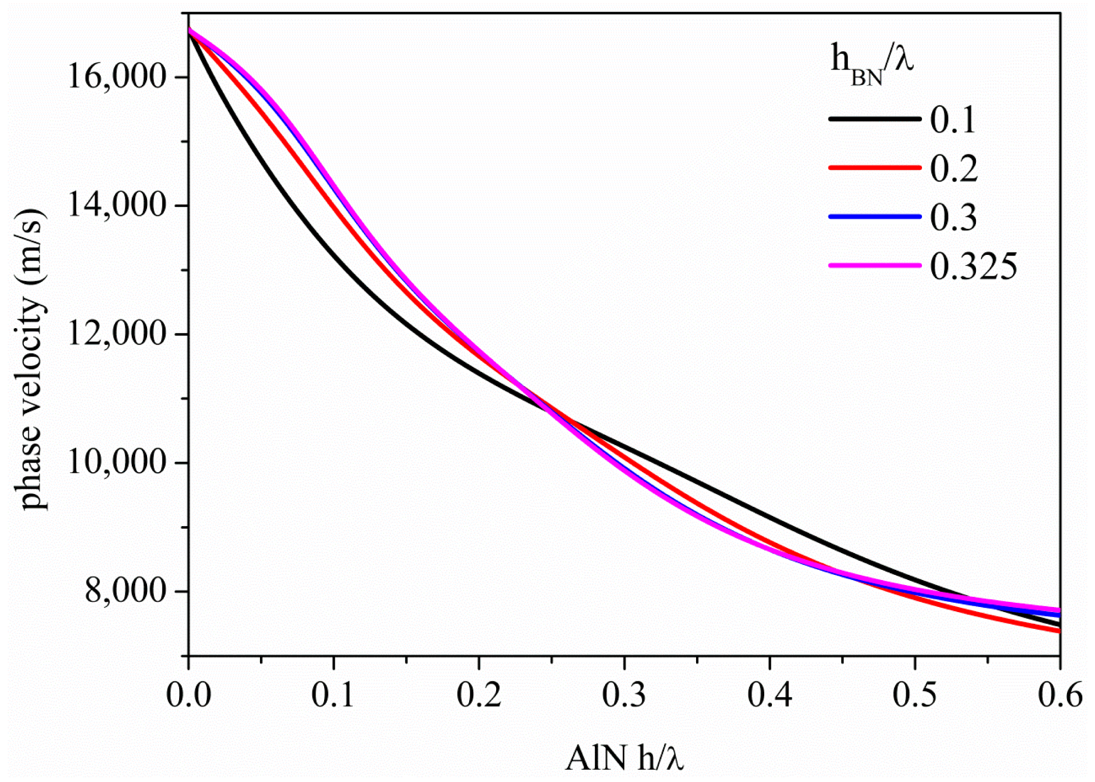
Figure 4 shows the S0 mode dispersion curves, i.e., the phase velocity vs. hAlN/λ, along the BN/AlN composite plates, for different BN plate thicknesses (hBN/λ = 0.1, 0.2, 0.3 and 0.325). As can be seen, for hAlN/λ∼0, the velocity equals that of the bare BN plate, but increasing the hAlN/λ, the mode phase velocity gradually decreases and asymptotically reaches the AlN SAW velocity for hAlN/λ > 1. The presence of the AlN film lowers the mode velocity, but has the great advantage of increasing the coupling coefficient of the composite plate with respect to that of the bare BN plate, as shown in the next paragraph.
3.3. The Coupling Coefficient Dispersion Curves
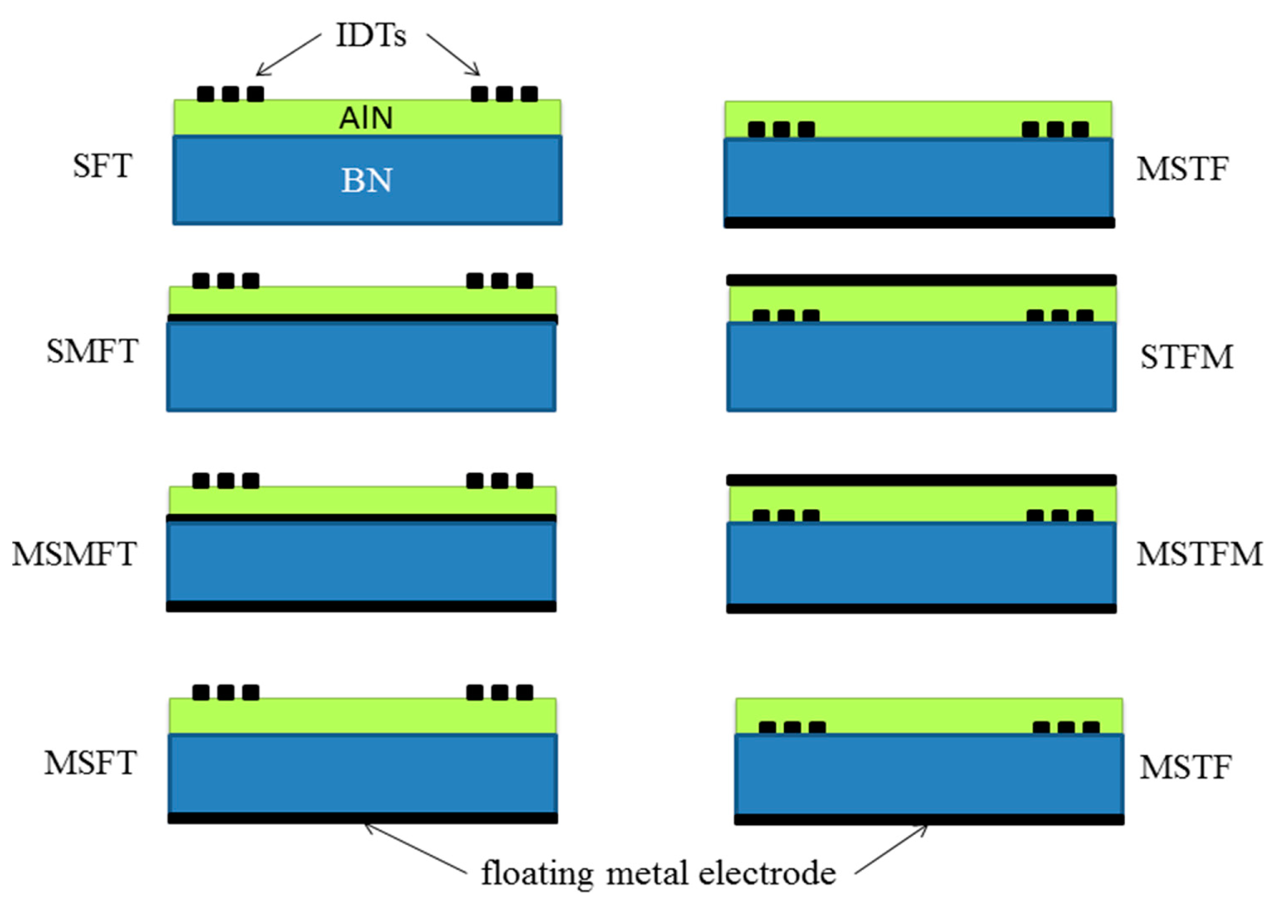
The bare wz-BN plate is impractical for the development of an electroacoustic device, as its K2 is weak, but this can be improved by covering the plate with a thin piezoelectric film, such as AlN, and selecting the proper electrical boundary conditions. The waveguide modes are excited and detected by the IDTs patterned on one surface of the AlN film: the application of an alternating electrical potential to one of the IDTs imposes an alternating strain field in the AlN film, which launches a mechanical wave into the composite plate. When the acoustic mode reaches the second transducer, it generates an electrical signal, which conveys information about the attenuation and phase delay experienced by the wave as it travels through the plate. By placing the IDTs on the AlN surface or at the BN/AlN interface, with or without one or two metallic layers opposite the IDTs, eight different electroacoustic coupling structures can be implemented, as depicted in Figure 5.
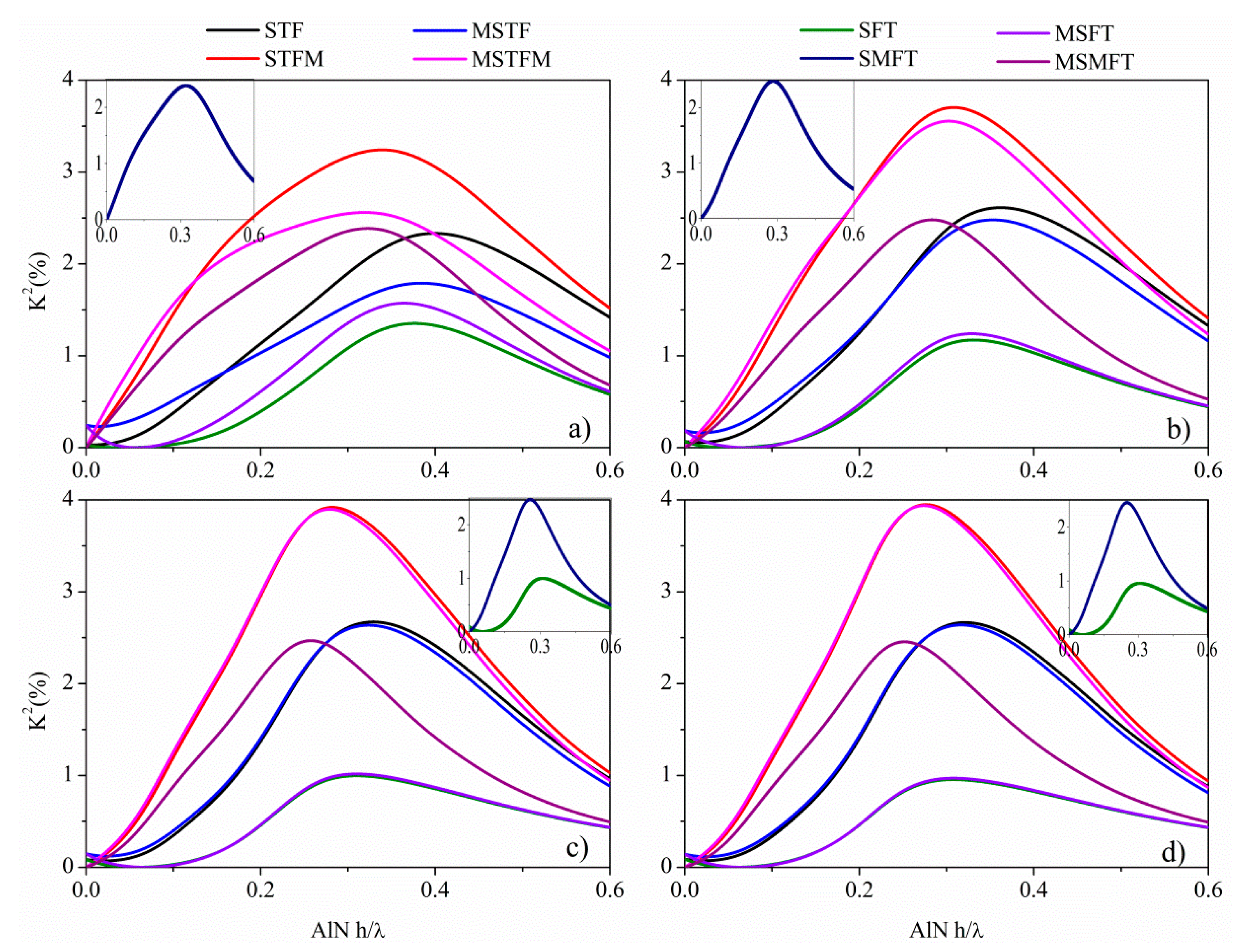
The configuration called substrate/film/transducer (SFT) refers to a composite plate with the IDTs positioned on the AlN free surface: when a floating metallic plane (M, metal) is placed at the AlN/BN interface and/or at the BN free surface, the configurations are called SMFT, MSMFT or MSFT. The configuration called substrate/transducer/film (STF) refers to a composite plate with the IDTs positioned at the AlN/BN interface: when the metallic plane is positioned at the AlN free surface and/or at the BN free surface, the configurations are called STFM, MSTFM or MSTF. The K2 is a measure of the electrical to acoustic energy conversion efficiency, and it was approximated to be 2[(vf − vm)/vf], where vm and vf are the velocities calculated in the short-circuited and free boundary condition, in the approximation of an infinitesimally-thin perfectly-conductive floating electrode and IDTs. The K2 dispersion curves were studied for the eight BN/AlN-based configurations, for different BN and AlN thicknesses normalized to the acoustic wavelength, hBN/λ and hAlN/λ, in the range 0.00001 to 0.6 with a step size of 0.0001. These curves were obtained taking into account only the electric loading from the IDTs and the metal floating plane. Figure 6 shows the K2 vs. hAlN/λ dispersion curves of the eight coupling structures, for hBN/λ = 0.1, 0.2, 0.3 and 0.325: the insets show those K2 dispersion curves that are not clearly distinguishable as a consequence of their partial overlapping with other curves. As can be seen, the K2 of the BN/AlN plate depends very strongly on the electrical boundary conditions and on the BN and AlN layers thickness, and it reaches values higher than that of the single AlN piezoelectric film (0.28%).
For hAlN/λ∼0, the K2 of each configuration is small, but with increasing the AlN thickness, it increases and reaches a peak; for hAlN/λ ≫ 1, the K2 moves toward the K2 of the SAW that propagates in the (0001) plane of the AlN semi-infinite substrate. A K2 as high as ∼4% can be obtained at hAlN/λ ∼ 0.27 with the STFM and MSTFM structures on hBN/λ = 0.325, for v∼10,300 m/s. In general, the coupling configurations with the metal floating plane placed on one surface of the AlN layer (STFM, MSTFM) have a higher electromechanical coupling coefficient than that of the configurations with a free AlN surface (SFT, MSTF, MSFT), because the electric field strength through the AlN thin plate is higher than that between the IDT electrodes. The metallization on the AlN side opposite the IDTs strongly enhances the vertical electric field in the AlN layer.
The STFM and MSTFM coupling structures are the most efficient between the eight, and Table 2 lists the highest K2 values that are obtainable by these two configurations for different BN/AlN thicknesses, together with the corresponding phase velocity.
All of the data listed in Table 2 refer to a Lamb-like wave with two non-null particle displacement components, U1 and U3; thus, such configurations are not suitable for operation in liquids, but only in a vacuum or air.
As mentioned previously, the AMs can propagate along the BN/AlN composite plate only for a limited AlN thickness range that depends on the underlying BN layer thickness. Table 3 lists the highest AlN thicknesses that still allow the AMs' propagation on the BN/AlN plates, the K2 and the velocity of the most efficient coupling configuration between the eight.
The AMs K2 is lower than that of the Lamb modes of Table 2, but the velocity is greater and suitable for achieving very high operation frequencies (in the GHz band) with micron feature-sized IDTs.
All of the calculations listed in Tables 2 and 3 were performed taking into account only the electrical loading of the IDTs and the metal plane. A subsequent investigation accounting both for the electrical and mass loading of the IDTs and the metal electrode was performed; the effect of the metal electrode thickness and material type (Pt, Mo and W) was studied for the S0 and AMs-based coupling structures listed in Tables 2 and 3. Different metal thickness ranges were studied relative to the AMs (hm/λ = 0.0001 to 0.005, step size of 0.0001) and S0 mode (hm/λ = 0.001 to 0.01, step size of 0.001): the ranges were properly chosen, so as not to excite the propagation of unwanted acoustic modes. In the case of the AMs, the K2 does not change with respect to the value calculated taking into account only the electric loading effect, but it decreases when hm/λ is comparable with hAlN/λ, whatever the metal type. In the case of the S0 modes, a quite small improvement (2.65%) on K2 can be obtained for the STFM configuration for the Mo electrode with thickness hm/λ = 0.007 and for hBN/λ = 0.2 to 0.325; the highest improvement in K2 (from 7% to 10%) can be obtained for the MSTFM configurations with the W electrode, for hm/λ = 0.09.
4. BN/AlN-Based Acoustic Waveguides for Sensing Applications
When an electroacoustic device is used for sensor applications, its output signal (a frequency and/or attenuation shift) is produced by the interaction between the acoustic wave (AW) and the chemical, biological or physical input to be measured. This interaction perturbs the AW characteristics, such as velocity and/or attenuation, through mechanical, acoustoelectric or viscoelastic coupling between the input stimulus to be measured and the acoustic wave field. For example, when an AW device is used for chemical vapor sensing, the wave propagation path is covered by a gas-specific sensing film: when this film is exposed to a gas, mechanical and electrical perturbations in the film will produce a shift in the resonant frequency of the acoustic wave device oscillator. Alternatively, by measuring the AW attenuation and the frequency shifts, one can determine the viscosity and density of a fluid that contacts these sensors. Generally the sensors based on electroacoustic devices are small, relatively inexpensive, quite sensitive and able to measure a wide variety of different input quantities [13].
4.1. Mass Sensors
The most common sensing application of the electroacoustic devices is based on the gravimetric principle for mass detection. A mass accumulation on the device surface changes the surface density of the propagating medium, hence resulting in a wave velocity shift. A mass sensor based on a high-frequency device exhibits superior performances: the higher the frequency, the higher the sensor sensitivity and resolution. If the added mass consists of an ideal thin elastic film that moves synchronously with the oscillating surface, the fractional velocity change-to-added mass ratio defines the sensor's gravimetric sensitivity S = [(v − vl)/vl]/m, m = ρ·h, ρ and h being the added layer's mass density and thickness, v and vl the unloaded and mass-loaded plate's phase velocity. Tables 2 and 3 list the sensitivity data of the S0 Lamb modes and the AMs propagating along the BN/AlN structures. Since the gravimetric detection can occur either on the AlN or BN plate surface, two normalized gravimetric sensitivity values, S and S′, were calculated for each AM and S0-based configuration. S has been calculated as S = [(v − v0)/v0]/(ρh/λ), where v0 and v are the wave velocities along the bare plate and the plate covered by a thin film, ρ is the film mass density and h/λ is the film thickness normalized to the wavelength. As can be seen, the AMs are more sensitive than the S0 modes, and the AlN side of the composite plate is more sensitive than the BN side, irrespective of the thickness of both materials, the energy confinement at the BN side being lower than that at the AlN side. As an example, for λ = 10 μm, the AMs-based mass sensor (BN = 0.1λ = 1 μm, AlN = 0.013λ = 0.13 μm) shows S = −123 m2/Kg, K2 = 0.25% and f = 1613 MHz, and the S0-based sensor (BN = 0.325λ = 3.25 μm, AlN = 0.274λ = 2.74 μm) shows S = −58 m2/Kg, K2 = 4% and f = 1028 MHz. These sensors show superior performances as compared to the SAW mass sensors implemented on STx-quartz, yx-, yz-and 128° tilted LiNbO3, for which S = −36, −29, −21 and −31 m2/Kg, K2 = 0.12, 1.56, 4.82 and 4.60% and f = 316, 377, 340 and 380 MHz, respectively [14].
4.2. Viscosity Sensor
The AMs are a very attractive choice for sensing applications in liquids, as they have only one source of attenuation, the friction between the surface plate and the adjacent liquid, while the S0 wave propagating in thick plates bordered by a liquid becomes a leaky wave due to the significant value of particle displacement normal to the plate surface and the radiation of compressional waves into the liquid. By monitoring the perturbations of the AMs propagation characteristics, such as the frequency and attenuation, one can measure the liquid density, viscosity, conductivity, permittivity and small mass changes. Although the AMs' gravimetric sensitivity was calculated in vacuum, it is a parameter of primary importance in the calculation of the sensitivity of a sensor for determining the viscosity of a fluid that contacts the device surface. The oscillation of the device surface contacting the liquid environment leads to entrainment of a thin liquid boundary layer near the interface that vibrates with a phase lag and an attenuated amplitude with respect to the surface vibration. The liquid layer velocity profile has an in-phase component that contributes to the viscous mass loading: a velocity shift arises from mass loading by the entrained viscous liquid layer of a thickness equal to the decay length of the AM field into the liquid, δ = [2η/ρω]1/2, ρ and η being the liquid density and shear viscosity, ω = 2πf and m′ = [ρlη/2ω]1/2 is the liquid mass that vibrates in phase with the plate mode. The velocity out-of-phase component contributes to the mode attenuation arising from the power dissipation in the liquid. The viscous coupling of the AMs to an adjacent Newtonian liquid results in both a change in the propagation velocity Δv/v = (S/2ω)·[ηωρl/2]1/2 and attenuation α = (S/2v0)·[ωρlη/2]1/2 of the mode, and these changes are proportional to the mass sensitivity of plate mode velocity S [15,16]. As an example, for λ = 100 μm, at a frequency of 160 MHz and for 50% glycerin/water mixture (η ≅ 6.879 mPa·s, ρ ≅ 1.144 g/cm3), δ ≅ 0.1 μm, Δv/v0 = 0.08% and α = 0.34 dB/cm, for the BN(0.1λ)/AlN(0.013λ)-based MSTFM configuration. This specific AM-based configuration, in addition to the advantage of having the highest mass sensitivity among the others, allows one to make measurements of the liquid viscosity that are not affected by the electric conductivity of the liquid that is being characterized, due to the presence of the metal electrode on the sensing side that short-circuits the electric field outside the plate. As the ability to detect perturbations on the plate side is affected by the materials' combination and the electrical boundary conditions, the measurements of the electrical conductivity of the liquid can be carried out using those configurations that provide for the direct contact between the liquid and the unmetallized surface of the BN/AlN-based configuration.
5. Conclusions
We report on the observation of very high velocity guided modes along thin BN/AlN composite plates, which exist when the plate thickness is about an order of magnitude smaller than the wavelength, while maintaining the electromechanical coupling coefficient of the piezoelectric AlN overlayer. The propagation characteristics of very fast longitudinal modes, the Anisimkin Jr. plate modes, along wz-BN/AlN thin composite plates is studied for different BN and AlN thicknesses and electrical boundary conditions. The study of the S0 mode phase velocity and coupling coefficient K2 dispersion curves revealed that eight different coupling configurations are allowable showing a K2 as high as about 4% and a very high phase velocity (up to about 16,700 m/s). The gravimetric sensitivity of the BN/AlN-based configurations was theoretically predicted, specifically addressing the design of enhanced coupling, microwave frequency mass sensors based on AMs and S0 modes, for applications in probing the solid/liquid interface and in a gaseous environment. The acoustic performances of these structures, such as the longitudinal polarization, the high K2 and remarkable high phase velocity, suggests the novelty and the advantages of the AlN and BN combination, suitable for the development of a small, completely integrated sensor for monitoring the liquid properties. BN/AlN is a very promising substrate material suitable for developing GHz-band devices with enhanced electroacoustic coupling efficiency and suitable for working in a liquid environment.
Conflicts of Interest
The author declares no conflict of interest.
References
- Anisimkin, I.V. New type of an acoustic plate mode: Quasi-longitudinal normal wave. Ultrasonics 2004, 42, 1095–1099. [Google Scholar]
- Gulyaev, Y.V. Propagation of the Anisimkin Jr.' plate modes in LiNbO3 and Te single crystals. Proceedings of the 2008 IEEE International Ultrasonics Symposium (IUS), Beijing, China, 2–5 November 2008; pp. 2221–2224.
- Anisimkin, V. General Properties of the Anisimkin Jr. Plate Modes. IEEE Trans. Ultrason. Ferroelectr. Freq. Control 2010, 57, 2028–2034. [Google Scholar]
- Anisimkin, V.I.; Pyataikin, I.I.; Voronova, N.V. Propagation of the Anisimkin Jr.' and Quasi-Longitudinal Acoustic Plate Modes in Low-Symmetry Crystals of Arbitrary Orientation. IEEE Trans. Ultrason. Ferroelectr. Freq. Control 2012, 59, 806–810. [Google Scholar]
- Caliendo, C.; lo Castro, F. Quasi-linear polarized modes in y-rotated piezoelectric GaPO4 plates. Crystals 2014, 4, 228–240. [Google Scholar]
- Hu, C.; Kotake, S.; Suzuki, Y.; Senoo, M. Boron nitride thin films synthesized by reactive sputtering. Vacuum 2000, 59, 748–754. [Google Scholar]
- Deng, J.-X.; Zhang, X.-K.; Yao, Q.; Wang, X.-Y.; Chen, G.-H.; He, D.-Y. Optical properties of hexagonal boron nitride thin films deposited by radio frequency bias magnetron sputtering. Chin. Phys. B 2009, 18, 4013–4018. [Google Scholar]
- Chen, X.; Sun, L.; Yang, B.; Guo, Y.; Wu, X. Research on the piezoelectric response of cubic and hexagonal boron nitride films. Optoelectron. Lett. 2012, 8, 117–120. [Google Scholar]
- Sun, L.; Chen, X. Research on the h-BN films for high frequency SAW devices. Proceedings of the SPIE 8202 International Conference on Optical Instruments and Technology: Solid State Lighting and Display Technologies, Holography, Speckle Pattern Interferometry, and Micro/Nano Manufacturing and Metrology, Beijing, China, 28 November 2011; pp. 82020L:1–82020L:7.
- Anisimkin, I.V.; Anisimkin, V.I. Attenuation of Acoustic Normal Modes in Piezoelectric Plates Loaded by Viscous Liquids. IEEE Trans. Ultrason. Ferroelectr. Freq. Control 2006, 53, 1487–1492. [Google Scholar]
- Shimata, K.; Sota, T.; Suzuki, K. First principles study on electronic and elastic properties of BN, AlN and GaN. J. Appl. Phys. 1998, 84, 4951–4958. [Google Scholar]
- Landolt-Börnstein, Group III; Springer-Verlag: Berlin, Germany, 1979; Volume 11.
- Ballantine, D.S.; White, R.M.; Martin, S.J.; Ricco, A.J.; Zellers, E.T.; Fye, G.C.; Wohltjen, H. Acoustic Wave Sensors: Theory, Design, & Physico-Chemical Applications; Academic Press INC.: San Diego, CA, 1997. [Google Scholar]
- Caliendo, C. Theoretical investigation of high velocity, temperature compensated Rayleigh waves along AlN/SiC substrates for high sensitivity mass sensors. Appl. Phys. Lett. 2012, 100. doi.org/10.1063/1.3675619. [Google Scholar]
- Wu, J.; Zhu, Z. Sensitivity of Lamb Wave Sensors in Liquid Sensing. IEEE Trans. Ultrason. Ferroelectr. Freq. Control 1996, 43, 71–72. [Google Scholar]
- Nayfeh, A.H.; Nagy, P.B. Excess attenuation of leaky Lamb waves due to viscous fluid loading. J. Acoust. Soc. Am. 1997, 101, 2649–2658. [Google Scholar]


| Material | K2 (%) | SAW (m/s) | LBAW (m/s) | SHBAW (m/s) | SVBAW (m/s) |
|---|---|---|---|---|---|
| c-AlN | 0.28 | 5,607 | 10,287 | 5,814 | 6,089 |
| wz-BN | 0.04 | 9,719 | 16,781 | 11,027 | 10,587 |
| Configuration | K2max (%) | v (m/s) | S (10−4 m2/Kgλ) | S′ (10−4 m2/Kgλ) | |
|---|---|---|---|---|---|
| STFM | 0.1/0.34 | 3.24 | 9,754 | −4.2 | −0.87 |
| 0.2/0.31 | 3.70 | 9,885 | −5.0 | −0.75 | |
| 0.3/0.28 | 3.92 | 10,204 | −5.6 | −0.66 | |
| 0.325/0.27 | 3.94 | 10,351 | −5.8 | −0.61 | |
| MSTFM | 0.1/0.32 | 2.56 | 9,941 | −4.5 | −0.66 |
| 0.2/0.3 | 3.55 | 10,024 | −5.1 | −0.61 | |
| 0.3/0.29 | 3.90 | 10,200 | −5.6 | −0.79 | |
| 0.325/0.274 | 3.94 | 10,284 | −5.8 | −0.67 | |
| K2 (%) | v (m/s) | S (10−4 m2/Kgλ) | S′ (10−4 m2/Kgλ) | Configuration | |
|---|---|---|---|---|---|
| 0.1/0.013 | 0.25 | 16,132 | −12.30 | −10.90 | MSTFM |
| 0.2/0.01 | 0.17 | 16,470 | −6.92 | −6.20 | MSTF |
| 0.3/0.004 | 0.14 | 16,664 | −4.72 | −4.40 | MSTF |
| 0.325/0.001 | 0.14 | 16,710 | −4.20 | −4.11 | MSTF |
© 2015 by the authors; licensee MDPI, Basel, Switzerland. This article is an open access article distributed under the terms and conditions of the Creative Commons Attribution license ( http://creativecommons.org/licenses/by/4.0/).
Share and Cite
Caliendo, C. Analytical Study of the Propagation of Fast Longitudinal Modes along wz-BN/AlN Thin Acoustic Waveguides. Sensors 2015, 15, 2525-2537. https://doi.org/10.3390/s150202525
Caliendo C. Analytical Study of the Propagation of Fast Longitudinal Modes along wz-BN/AlN Thin Acoustic Waveguides. Sensors. 2015; 15(2):2525-2537. https://doi.org/10.3390/s150202525
Chicago/Turabian StyleCaliendo, Cinzia. 2015. "Analytical Study of the Propagation of Fast Longitudinal Modes along wz-BN/AlN Thin Acoustic Waveguides" Sensors 15, no. 2: 2525-2537. https://doi.org/10.3390/s150202525