2.4.1. Human-Hand Detection Process
Hand detection has been widely discussed in the literature on perception systems for interaction between humans and electronic devices. New sensor technologies have facilitated the sensing of human body parts for remote control of avatars and robotic devices. 3D cameras such as RGBD or time-of-flight (ToF) cameras enable the extraction of human gestures and movements [
20], and it is anticipated that they can be used to control devices from a distance. Master-slave architectures such as haptic devices or infrared remote control have been widely used in previous works to move robots both with feedback [
21,
22] and without feedback [
23]. At present, visual sensors have replaced these systems in many cases because of their cost and versatility. Cameras allow the extraction of the hands of a user using a combination of several image processing techniques, such as skin colour segmentation (based on a combination of static and dynamic thresholds) [
24,
25], background subtraction using different scenes of a video stream [
26] and shape recognition based on morphological information (
i.e., curvature calculations and convexity defects [
27]). The depth information provided by RGBD and ToF sensors helps us to solve the two main drawbacks of this approach, namely, the dependence on the lighting of the scene and the distinction between background and user, in a simple and robust way. The ability to capture 3D data from a scene, which can be modelled like a point cloud, introduces the possibility of determining hand poses by means of depth clustering analysis. This analysis can be combined with some of the techniques used in RGB analysis, such as the use of morphological constraints [
28] or dynamic skin colour segmentation [
29]. The positions of the hands can also be obtained through more complex analysis, such as tracking the skeleton of the user [
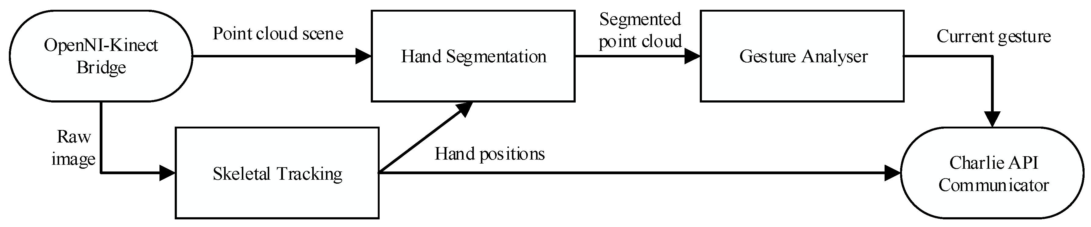
30]. In the latter case, there are several implementations of skeletal tracking available to the general public (OpenNI, Kinect SDK) that are sufficiently reliable for our proposed work. The proposed method involves several processing steps (
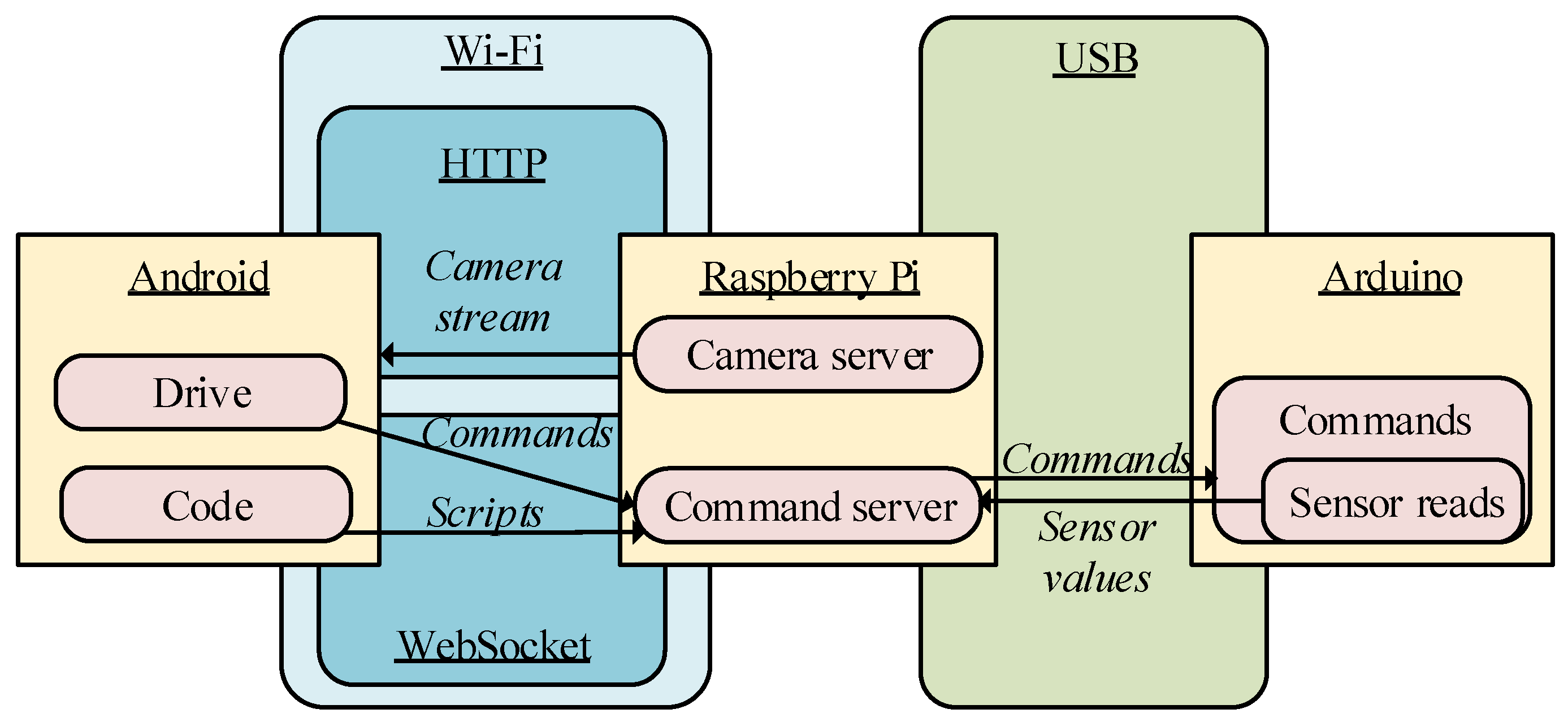
Figure 3):
Detecting the skeleton of the user
Segmenting the area contiguous to the hand (rough segmentation)
Splitting hand points and noise from the extracted area (fine segmentation).
Figure 3.
Data flow among the different software components of the application.
Figure 3.
Data flow among the different software components of the application.
Step 1: Using skeletal tracking
As the first step of hand segmentation, a skeleton tracking node provided by the manufacturer of the sensor (NiTE middleware with the OpenNI driver) is used. The tracking is carried out from the IR sensor and without using the RGB information. This is generally because IR sensors are less sensitive to changes of light in the scenario. Only interferences on the same wavelength could cause detection problems, but this is unlikely to occur in indoor environments and households which are lit by artificial light and their spectrum is away from infrared light. This has been empirically tested with different people and rooms. This basically means that the tracking system works properly with people of different races who may have varying skin colour and body shape. Besides, the tracking system can be used with people wearing any kind of clothes provided that the garments are not too voluminous. It is preferable for clothes to be as close fitting as possible. In our case, skeletal tracking is just for the upper body. The idea is to provide the least light-dependent and invasive system possible. In addition, the skeletal tracking can follow multiple users at the same time in the environment. The skeletal tracking can simultaneously follow multiple users in the scenario. This approach makes it easy to expand the capabilities of our system to the control of more than one target with a single sensor or to the collaborative control of the same target. The greatest disadvantages of the mechanism are the need for a starting pose for skeletal recognition and the need for the user to be positioned in front of the camera, with most of his or her body present in the field of view of the sensor.
In comparison with the official MS Kinect-SDK, the NiTE middleware offers greater flexibility for embedding it in an ultimate solution. Various binaries are provided that have been compiled for Windows and GNU/Linux systems, and in later versions, compatibility with ARM processors has been added, allowing the system to host applications on mobile devices and microcomputers. The maintainers of the most popular Linux distributions provide a ready-to-install package in the official repositories, and the maintainers of the Robot Operating System (ROS) middleware provide a package that is ready to add to the architecture of a standard ROS solution. Furthermore, in a comparison of the precision of the two skeletal tracking approaches, there are no noticeable differences between them in the normal use case [
31].
Step 2: Rough segmentation
Once the approximate positions of the two hands are located, the next step is the extraction of the points in their surroundings. The cloud is ordered in a k-d tree. A k-d tree is a data structure that represents a binary tree and is used for ordering a group of k-dimensional components. In this case, we are organising a cloud of points by their spatial coordinates to enable an efficient range search on the neighbourhood of the detected centre of the hand (
Figure 4).
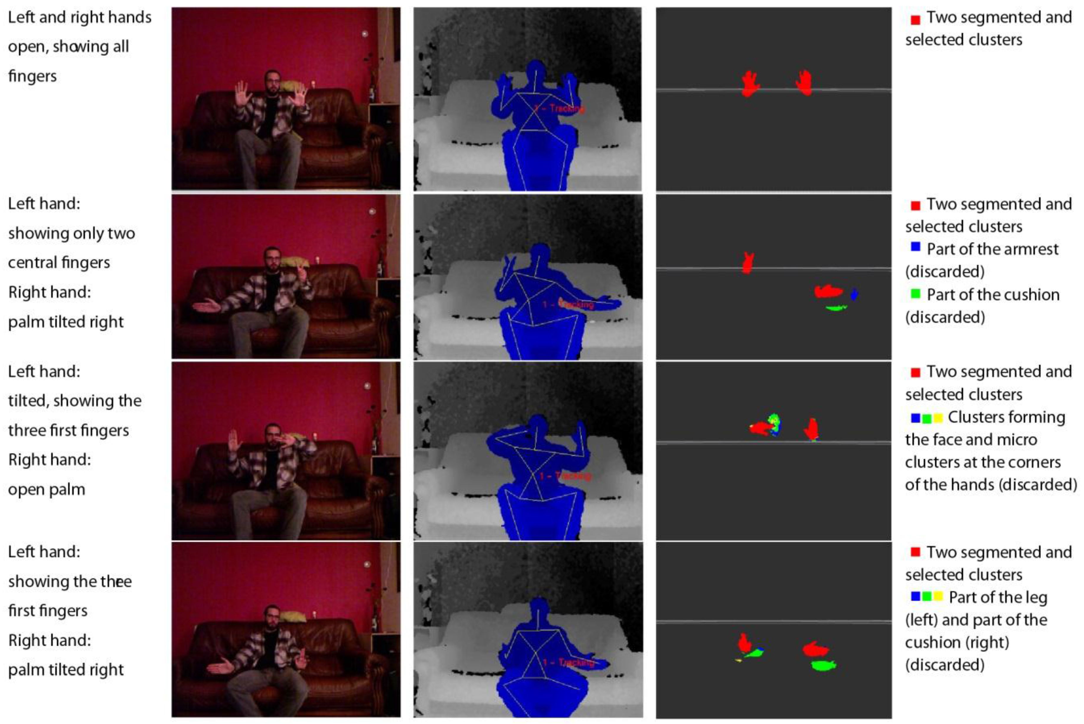
Figure 4.
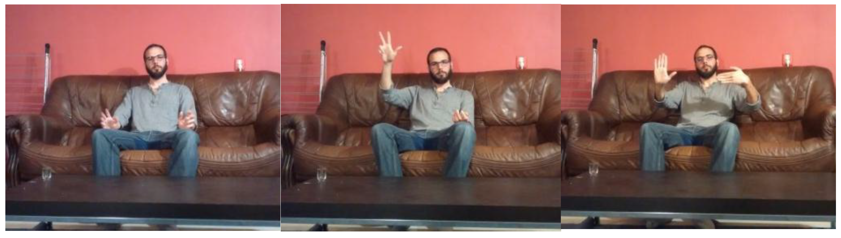
Representations of the detection of the human skeleton via the segmentation and filtering of a point cloud to detect the hands of a user sitting on a couch.
Figure 4.
Representations of the detection of the human skeleton via the segmentation and filtering of a point cloud to detect the hands of a user sitting on a couch.
For this step, a radius of interest of 24 cm around the centre is considered. This value is the sum, rounded up, of the average error on the hand position detection of a user in a sitting position (14.2 cm [
31]) and half the average length of a male hand among members of the European ethnic group with the largest hand size (19.5 cm) [
32].
Step 3: Fine segmentation
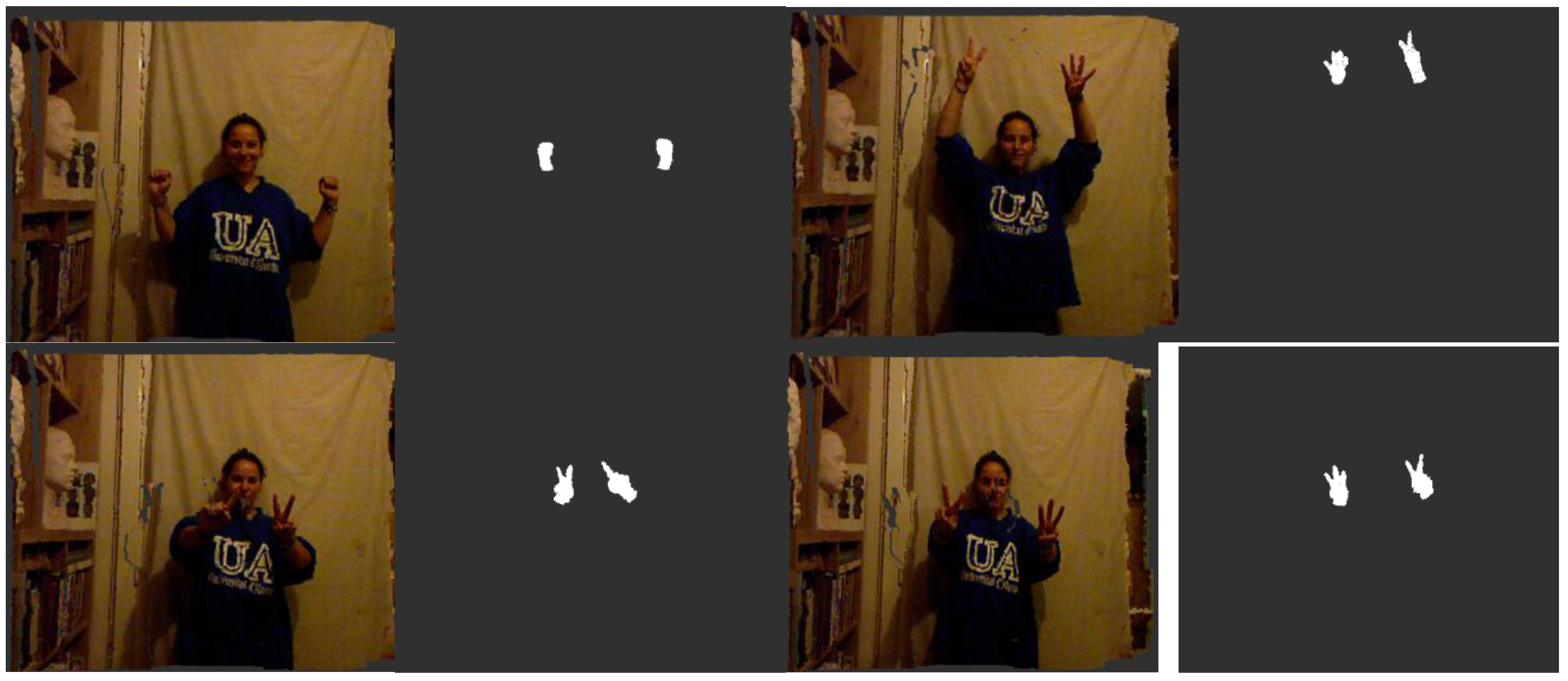
The final processing step removes potential spurious elements that appear in the segmented area because of their proximity to the hands of the user. These elements could be objects in the scene as well as the clothes of the user or other parts of the body (e.g., chest, hair). Because the segmentation is initially centred on the palm of the hand, we assume that the largest continuous element in the extracted cloud will be the palm, the fingers attached to the palm and part of the arm. Then, the analysis is performed by defining a cluster as a set of points that are closer than 3 cm to another point in the cluster. This margin is needed because when the hand is located in a deep region of the scene, the density of points is lower and the segmentation could miss one or more fingers. Several constraints can be formulated to avoid false cluster identification, such as a minimum cluster size (to avoid falsely identifying noise as a signal when the hand is out of the scene) or a maximum cluster size (to avoid identifying one or more additional adjacent elements as part of the hand). Experimentally, we determined that reasonable values for these constraints are 100 points for the minimum size and 30,000 points for the maximum size (
Figure 5).
Figure 5.
Visualisations of the original coloured point cloud and the final segmented hands of a user standing up.
Figure 5.
Visualisations of the original coloured point cloud and the final segmented hands of a user standing up.
2.4.2. Gesture Recognition
Various approaches are used in the literature to address the problem of gesture classification. For example, classification can be performed based on pose estimation by imitating the skeletal tracking of the Kinect SDK [
33,
34] or through a combination of hand feature extraction (location, centroid, fingertips, silhouette) and machine learning (Hidden Markov Models [
35], k-Nearest Neighbours [
36], shape description [
37]), combining different techniques in each step to construct the best system for the target application.
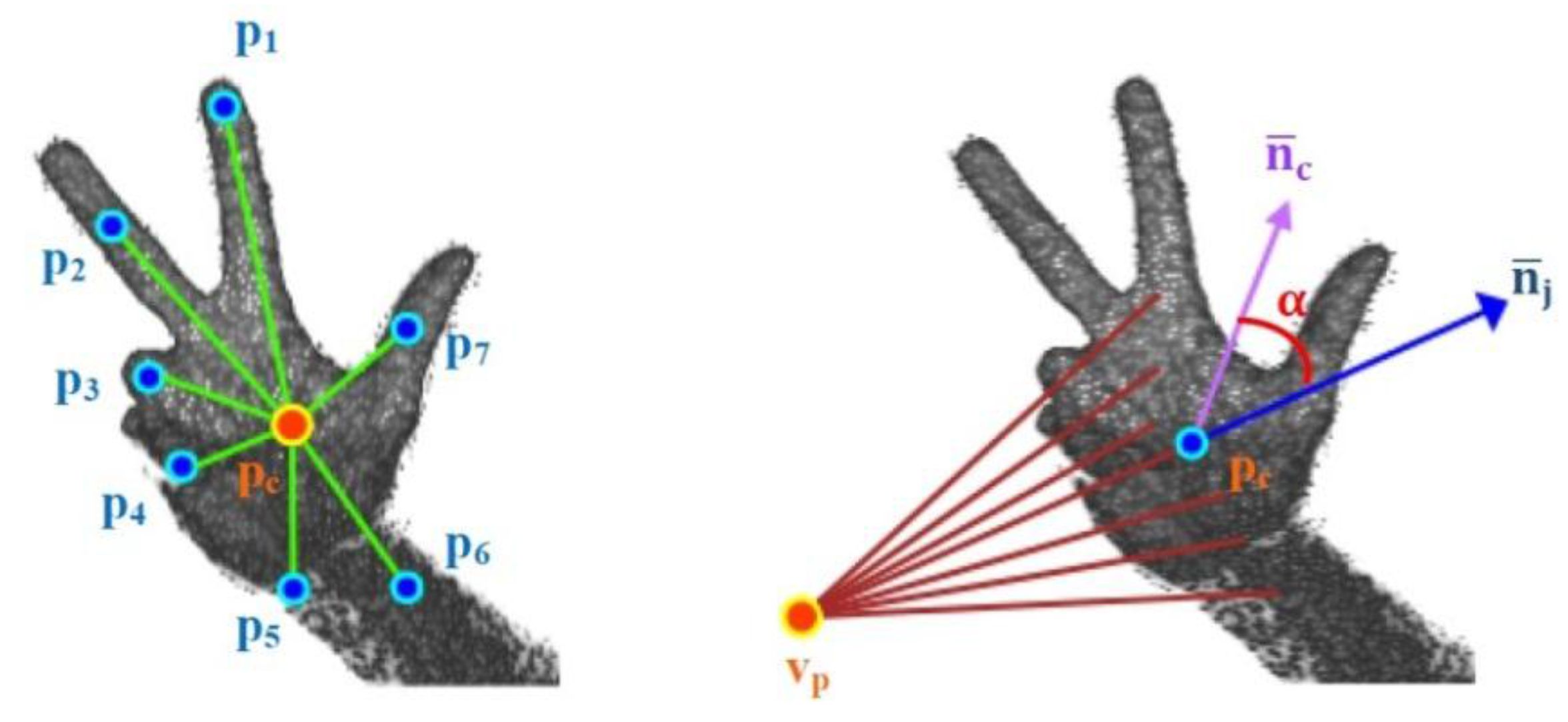
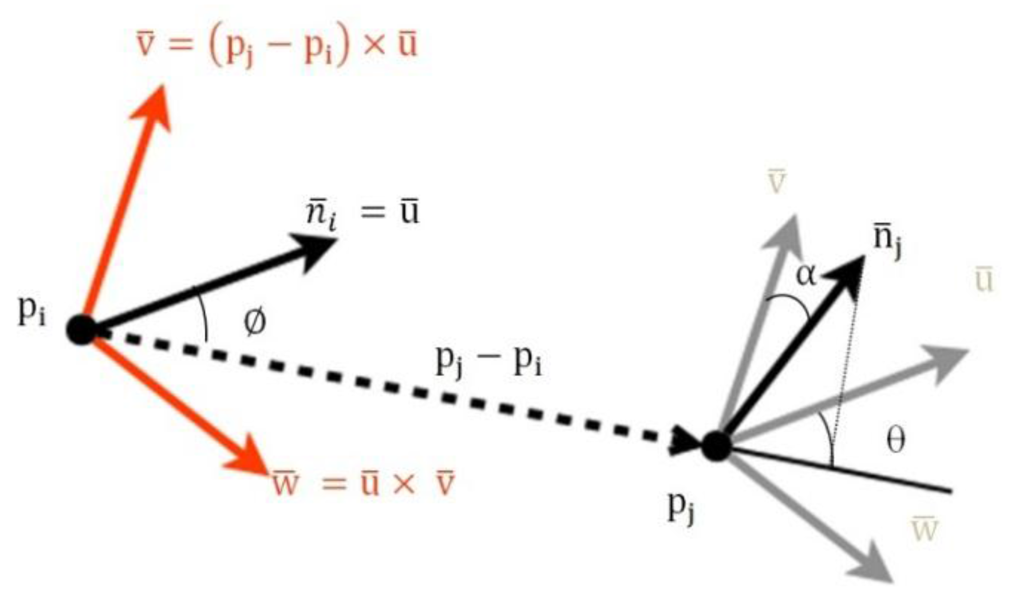
Once the hand is extracted, the process is split into two parts: training and detection. For both sub-processes, a descriptor of the segmentation result is computed. The descriptor used in our prototype is the Viewpoint Feature Histogram (VFH) [
38]. The VFH encodes the differences in angle–pitch (α), roll (∅) and yaw (θ)–between the normal vector of the centroid p
i of the point cloud that represents the hand and any other part of the cloud p
j in the Darboux frame (
Figure 6) [
39].
Figure 6.
Geometric variation between two points based on the framework of Darboux transformations.
Figure 6.
Geometric variation between two points based on the framework of Darboux transformations.
The reference frame centred on
is defined by:
where
Then, the geometric variation between the two points can be expressed as the relative difference between the directions of their normal vectors
and
, and it is calculated as follows:
where
represents the Euclidean distance between two points in the space.
This geometric variation is used to determine the geometric shape in a manner similar to that used other works, such as [
40], but in this case, it is applied to hand gestures. Additionally, the VFH incorporates information to encode the direction of the point of view. For this reason, the VFH is suitable for recognising gestures as well as for processes that require identifying the pose of an object (
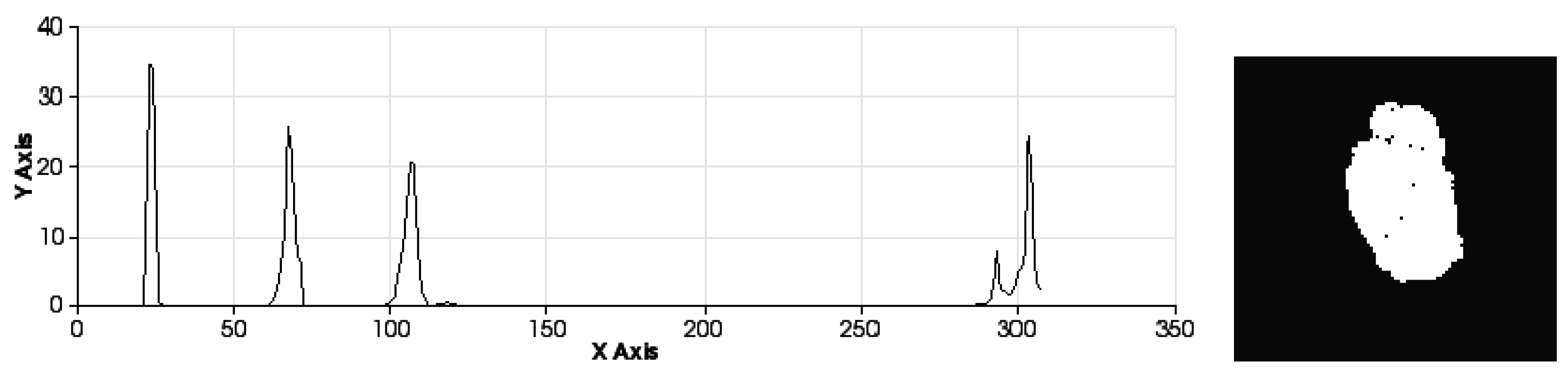
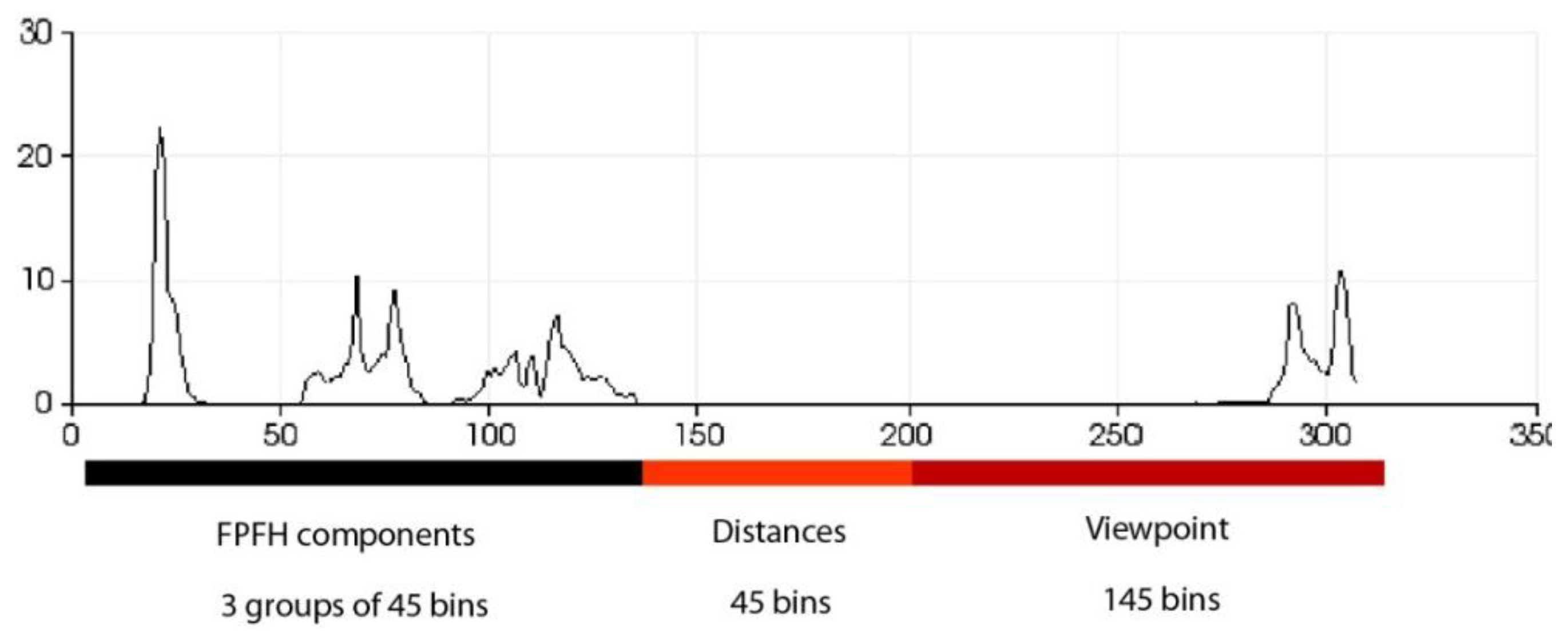
Figure 7). The VFH descriptor for each point on the hand (
Figure 7) is represented as a multi-dimensional histogram that accumulates the number of repetitions of a tuple
(
Figure 8) where each component is normalized to 100. Furthermore, as in any one-dimensional histogram, it is necessary to split the data into a specific number of divisions. Each of these divisions represents a range of values of each element of the tuple and graphically indicates the number of occurrences belonging to each range of values (
Figure 8). The descriptor normalizes its bins by the total number of points which represent the hand and also it normalizes the shape distribution component [
41].
Figure 7.
Viewpoint information of the VFH descriptor of a human hand.
Figure 7.
Viewpoint information of the VFH descriptor of a human hand.
Figure 8.
Description of the zones of the histogram.
Figure 8.
Description of the zones of the histogram.
This approach yields a descriptor that is well suited to our purpose because it is global, rapid to compute, independent of scale and dependent on pose (
Figure 9 and
Figure 10). This last feature will allow us to decide at the time of training whether two different poses should be considered to be the same gesture or different gestures (
Figure 11). Once the possible gestures are defined, several descriptors of the different frames of each gesture are stored. The method that is applied to match the current gesture with one of the trained gestures is similar to that used by Rusu
et al. [
31]. All the histograms that describe a gesture are regarded as 308-dimensional points (one dimension per bin) and are placed in a point cloud. Afterwards, the incoming gesture is placed on the cloud, and the 10 points (histograms of the analysed gestures) that are nearest to it are located. Because these points may be frames of the same gesture or of different gestures, the matching gesture is determined via weighted voting, based on the distances between the histograms.
Figure 9.
Sets of descriptors computed to recognise several left-hand gestures I. Descriptor in the left. Pose in the right.
Figure 9.
Sets of descriptors computed to recognise several left-hand gestures I. Descriptor in the left. Pose in the right.
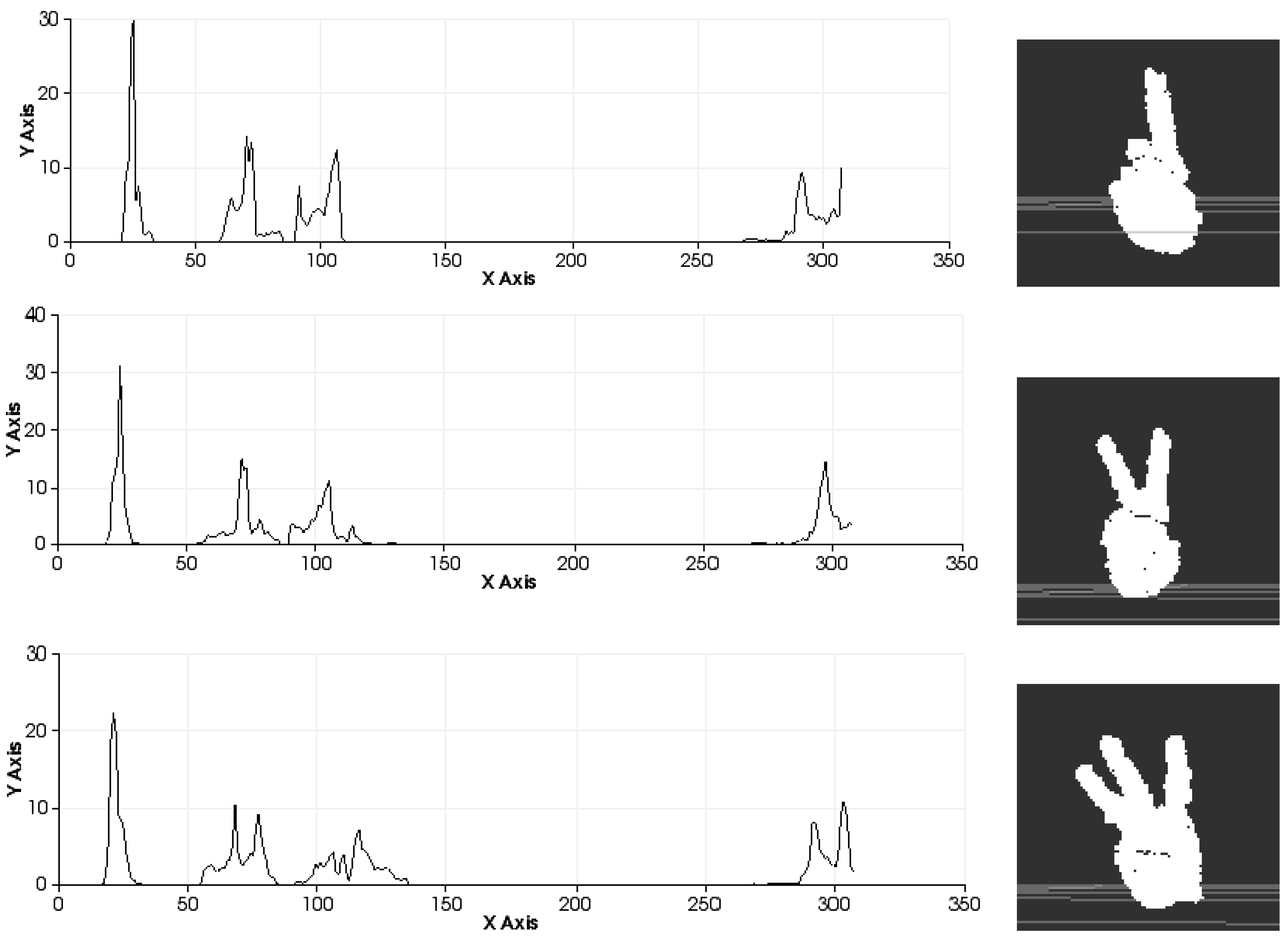
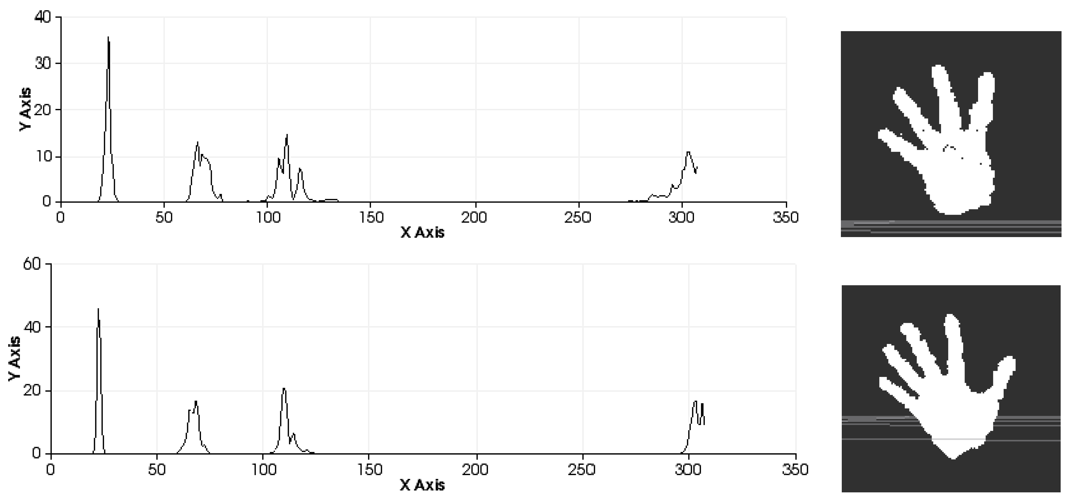
Figure 10.
Sets of descriptors computed to recognise several left-hand gestures II. Descriptor in the left. Pose in the right.
Figure 10.
Sets of descriptors computed to recognise several left-hand gestures II. Descriptor in the left. Pose in the right.
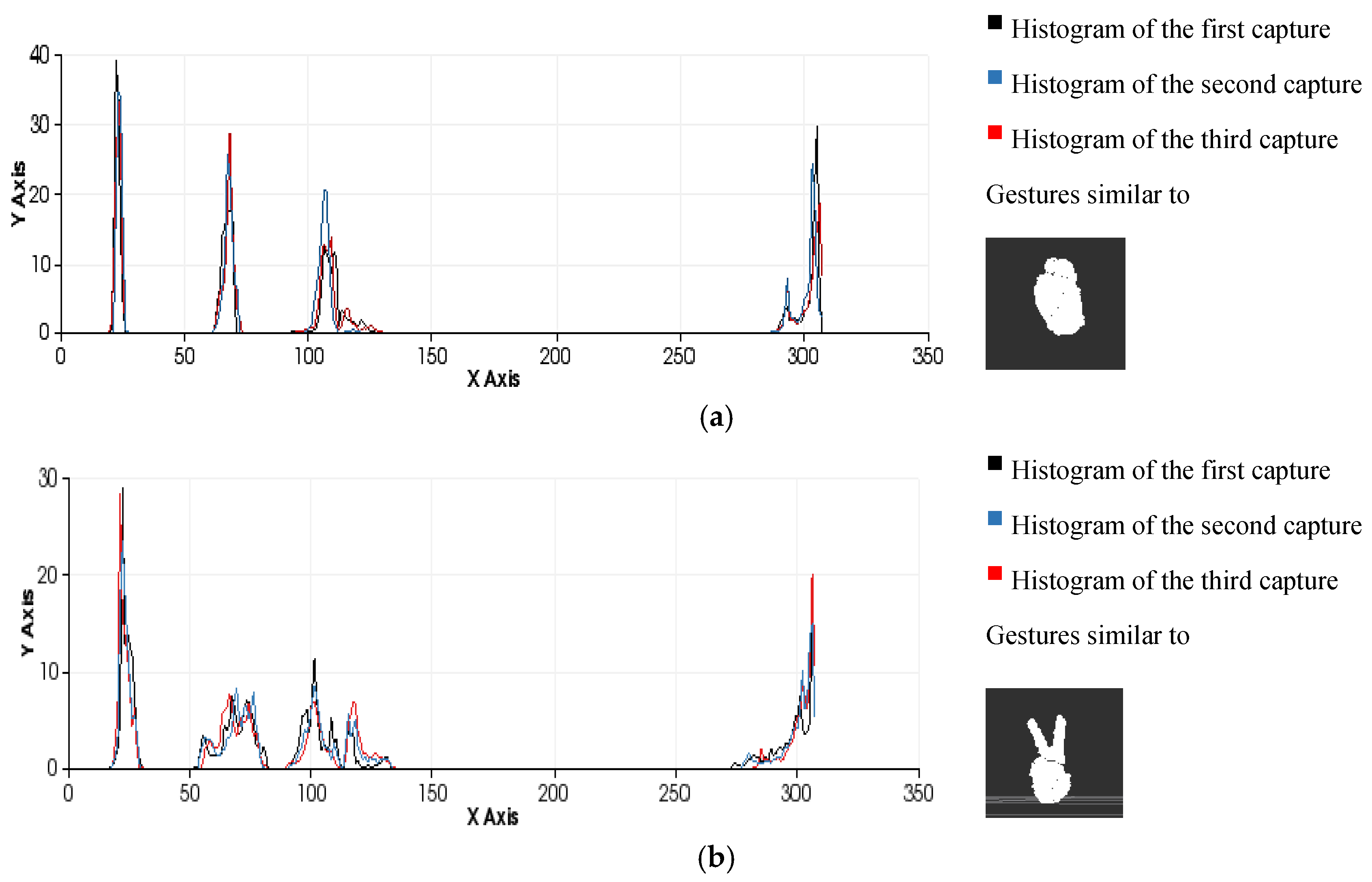
Figure 11.
Examples of the gesture classification process performed by comparing histograms using the minimum Euclidean distance as a similarity metric. (a) Gesture 0 ; (b) Gesture 2 .
Figure 11.
Examples of the gesture classification process performed by comparing histograms using the minimum Euclidean distance as a similarity metric. (a) Gesture 0 ; (b) Gesture 2 .
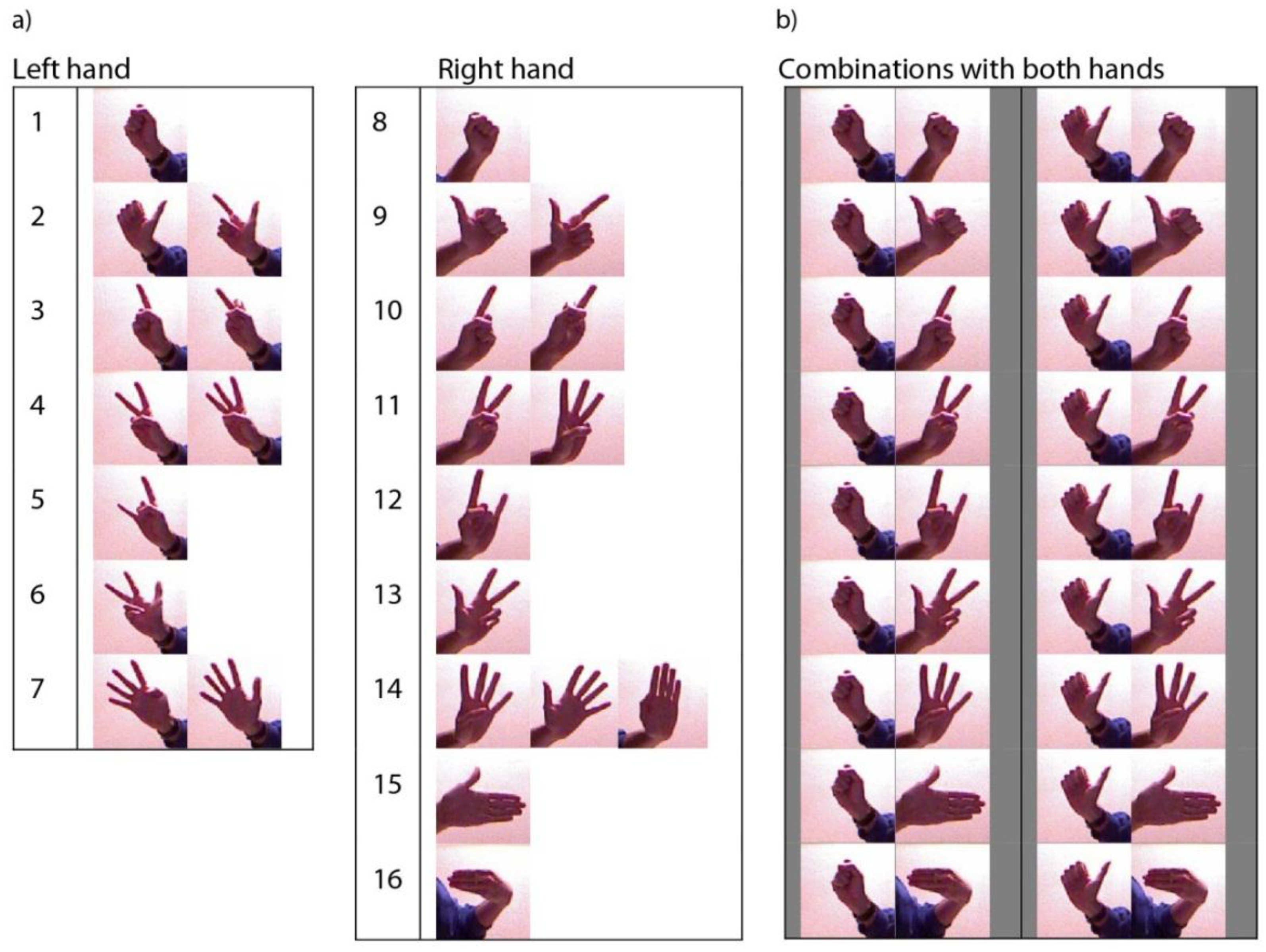
The effectiveness of the entire process (segmentation and recognition) is highly dependent on the number of different gestures to be distinguished and the differences between the gestures due to the variance in the morphological features and poses (
Figure 12). It is possible to perform pose-invariant recognition while training the algorithm, grouping the same figure in different poses as the same gesture and increasing the number of frames captured per gesture. In general, we can affirm that for a given number of gestures to be distinguished, a higher number of frames per gesture in the database will result in higher precision.
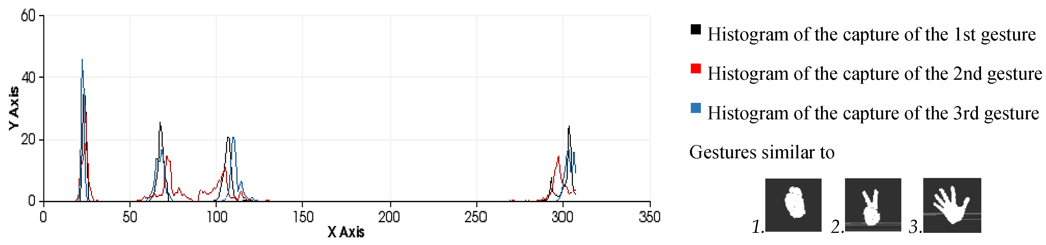
Figure 12.
Similarity measures computed during the classification process among three different human-hand gestures: gesture 0, gesture 2 and gesture 5 .
Figure 12.
Similarity measures computed during the classification process among three different human-hand gestures: gesture 0, gesture 2 and gesture 5 .
It is possible to distinguish several differences between histograms of each example (
Figure 9 and
Figure 10) with regard to the first part of the histogram representing the FPFH components encoded as a set of angle variations, such as pitch (α), roll (∅) and yaw (θ) (
Figure 8). All of these are calculated using the same number of repetitions per value.
Figure 9 shows the representation of 0 fingers by means of close hand gesture, and
Figure 10 shows five samples of the most common representations from 1 to 5 that can be represented with the hand gestures by extending fingers. A comparison between the first and fifth samples of
Figure 10, regarding the first part of the histograms, shows the changes in the dispersion of angle variations. Thus, the first sample shows that there are more bins with no zero values and the histogram has a greater distribution of angular values. That is to say, the first sample has more dispersion than the fourth or fifth sample. But also, the fifth sample shows that the angular values are more concentrated around three bins than in the remaining samples in
Figure 10. To summarise, that concentration occurs for different values in each histogram, resulting in sharp concentrations on an entropic background.
Comparison of all the figures denotes that the differences on the last part of histogram, which represents the viewpoint, are mainly caused by the changes in the position of the hand and the camera in the whole training process. Note that they are less related to the gesture morphology (
i.e., with the hand pattern shape which is being reproduced by the user). These variations can be observed in
Figure 12 which represents the overlap of three gestures.


