
Theory and Application of Magnetic Flux Leakage Pipeline Detection


Abstract
:1. Introduction
1.1. The Significance of Pipeline Defect Detection
1.2. The Brief Introduction of MFL

- So much qualitative analysis of the signal is needed that MFL is hardly applied in practice, because the actual complicated working conditions can’t match the laboratory conditions.
- It is quite sensitive to the running speed of the vehicle.
- The pipe wall must achieve complete magnetic saturation.
- It has a strong capability to detect large area while it is limited to the material surface and near surface; the detection of axial narrow and long defects is restricted.
- The probe is susceptible to the pipe wall, and its anti-interference ability is poor. When the materials used in the pipeline are mixed with impurities, there will be false data.
- The quantitative theory of defects needs to be further studied. There is no one-to-one correspondence between the shape of the defect and the signal characteristics of the detection.
- The height of the defect sometimes depends on the experience of the operator.
2. Principle, Model and Influence Parameter
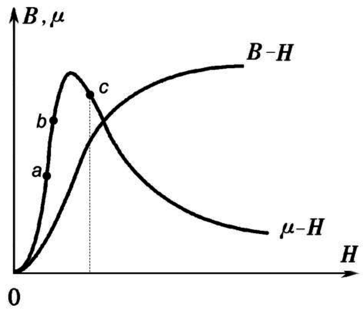
2.1. Principle of Magnetic Flux Leakage Detection


- AC magnetization. It can be used to detect a workpiece on which surface is rough, but AC magnetic field easily produces skin effects and eddy currents, and the depth of magnetization decreases with the increase of current frequency. Therefore, this method can only detect surface and near surface defects, but the intensity of AC magnetization is easy to control, the magnetic structure is simple, and the cost is low.
- DC magnetization. DC magnetization is divided into DC pulsating current and DC constant current magnetization, the latter being simpler than the former in structure; however, the excitation current is larger. It can detect more than 10 mm deep surface defects, and magnetization can be easily adjusted by controlling the size of the current, but it is difficult to achieve larger magnetizations, and demagnetization is needed every time it is used.
- Permanent magnet magnetization. This uses a permanent magnet as the excitation source. It has the same characteristics as DC magnetization, but the adjustment of intensity is less convenient than in DC magnetization. Permanent magnets can be made with permanent ferrite, aluminum and nickel cobalt permanent magnet materials and rare earth permanent magnet materials. Especially rare earth permanent magnet materials, because of the high energy nature, small volume and no need or electricity, have been well applied in magnetic flux leakage detection.
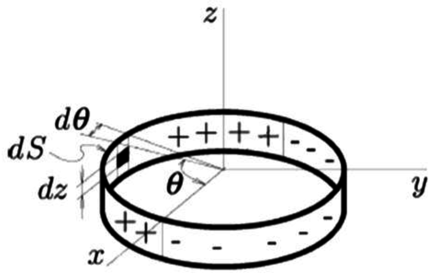
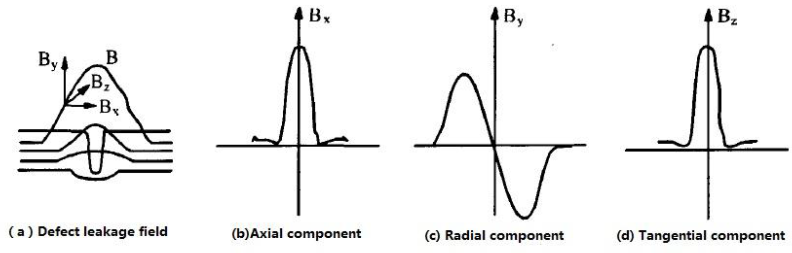
2.2. Analytical Model of the Magnetic Leakage Field
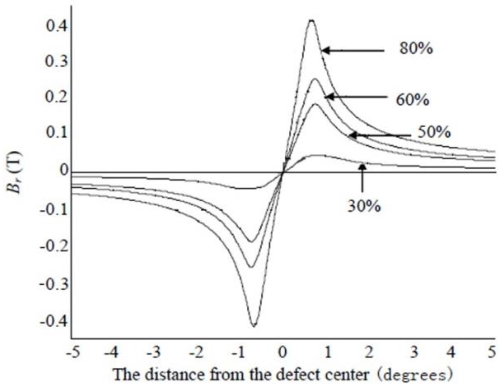
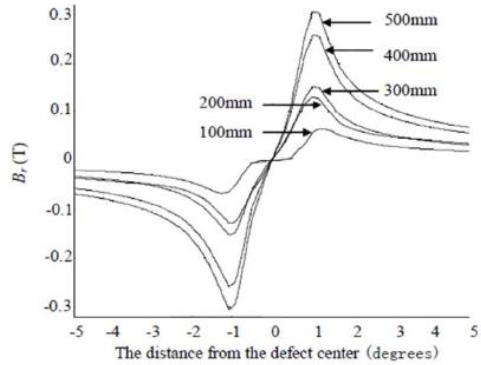
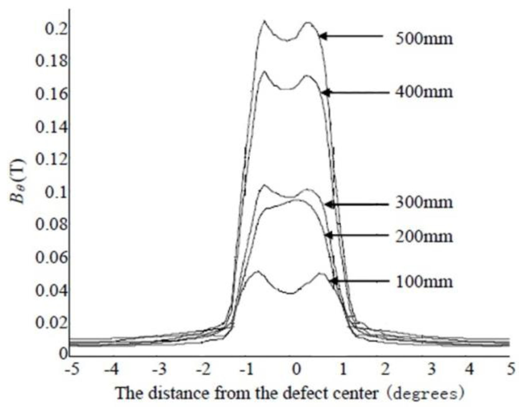
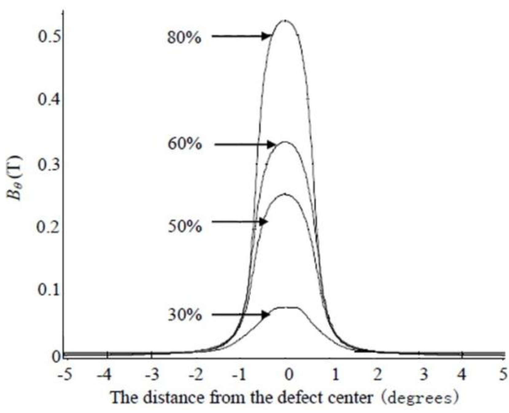
2.3. Defect Shape Influencing Parameters

3. Measurement and Processing
3.1. Measuring Methods and Sensors
- Electromagnetic induction method. Based on Faraday's law of electromagnetic induction, it is one of the most basic magnetic measurement methods. It can measure DC, AC and pulsed magnetic fields. Measuring instruments usually use induction coils, including impact galvanometers, flux meters electronic integrators and vibrating coil magnetometers [53,54].
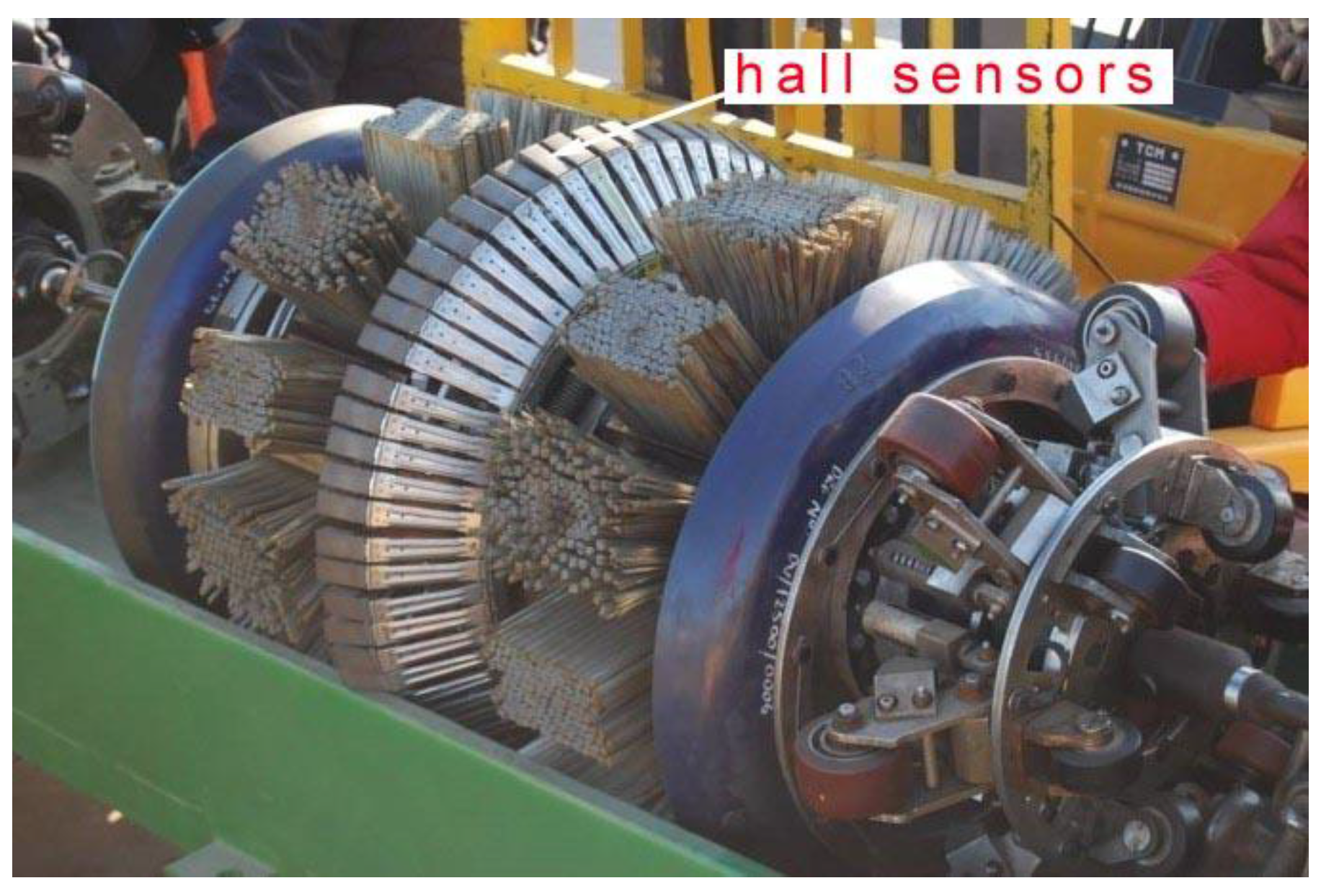
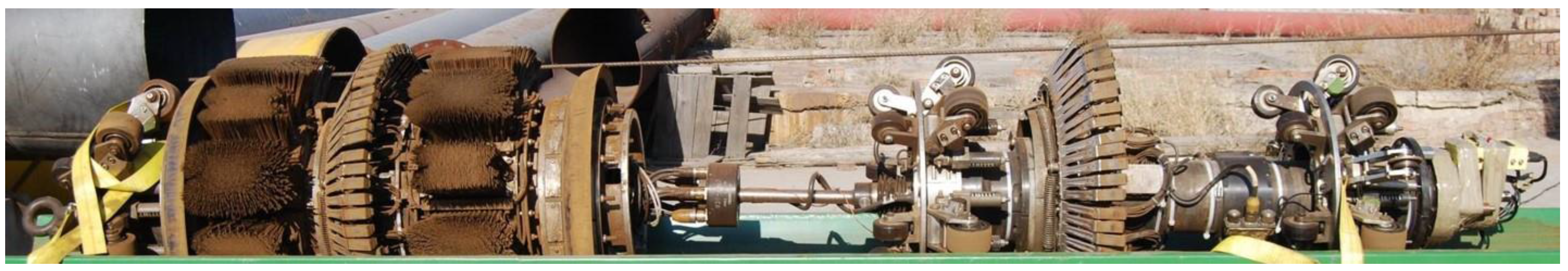
- Hall Effect method. The electromotive force is generated by the electric current in the magnetic field. The change of the magnetic field intensity can be obtained by measuring the electromotive force. Figure 10 shows a photo of a magnetic pig with the Hall sensors. Compared with other measurement components, the Hall component manufacturing process is mature, and the stability and the temperature characteristics are better, so it is the first choice for leakage magnetic field measurement. In order to improve the measurement coverage and control resolution and prevent undetected flaws, more pieces of the Hall element will for man array to compose a leakage magnetic probe according to a certain pattern. Multi-channel data acquisition is available in order to improve the clarity of pipeline defect detection. Finally in order to prevent the occurrence of angle deflection of a Hall element on the circuit board due to collision, vibration and other incidents, the package is encapsulated, which can not only ensure the detection sensitivity and accuracy of the leakage magnetic probe, but also guarantee the strength and reliability of the wire and the circuit board connection [57,58,59].Figure 10. Photo of the magnetic pig with the Hall sensors.
![Sensors 15 29845 g010]()
- Magnetic resonance imaging. By absorbing or radiating a certain frequency of electromagnetic wave in the magnetic field, some microscopic particles would induce resonance. The intensity of the magnetic field is obtained by measuring the degree of resonance. Due to different types of particle resonance, devices can be of various types, such as nuclear magnetic resonance magnetometers, electron spin resonance magnetometers, etc. The former is a measuring instrument with a constant magnetic field of the highest precision, so it can be used as a reference for magnetic transmission devices [60].
- Magneto optical method. This approach utilizes the magneto-optical and magneto-stricture effects. Optical fiber sensors based on this method have unique advantages, which include being usable in harsh environments.

| Magnetic Sensor | Measurable Intensity/T |
|---|---|
| Induction coils | 10−13~10 |
| Hall components | 10−5~10 |
| Magnetic flux gate | 10−12~10−13 |
| Magnetic sensitive diode | 10−6~10−1 |
| Magnetic sensitive transistor | 10−6~10−1 |
| Magnetic resistance | 10−11~10−3 |
- Induction coils. When the coils move on the surface of the pipe, the leakage magnetic field caused by a defect can cause a change of the magnetic flux through the coil. The induced electromotive force generated by the magnetic leakage field can be expressed by the following formula:where N refers to the number of the coils; ∅ refers to the magnetic flux leakage flux in the coils; B refers to the magnetic induction intensity; S refers to the cross-sectional area of the coils. The relative variation of the magnetic field is measured by the induction coil, which is sensitive to high frequency signals. The sensitivity depends on the number of coils and the relative movement speed, and it is easily influenced by the speed of the coil movement.
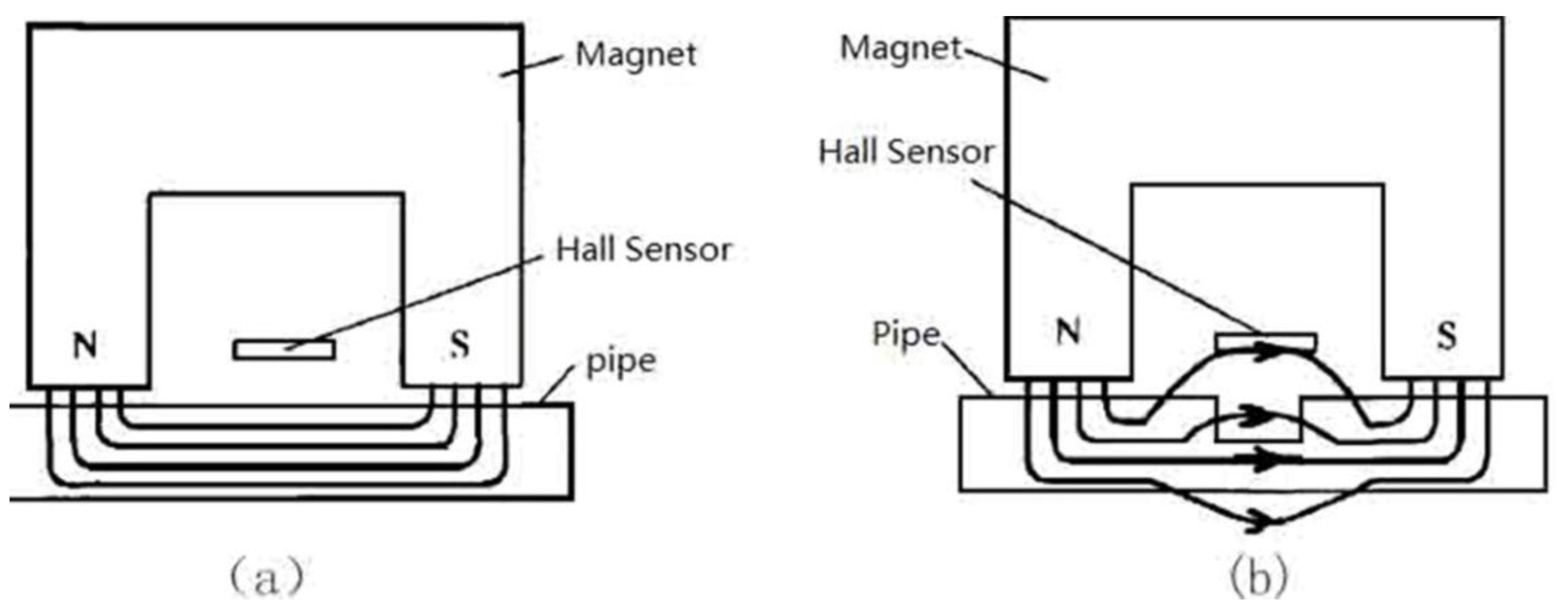
- Hall components. When the current movement direction is perpendicular to the direction of the magnetic induction intensity [62], Hall components on both sides produce a Hall electromotive force. It can be expressed by the following formula:where VH refers to the Hall electromotive force; KH refers to the Hall coefficient; I refers to electric current; B refers to the magnetic induction intensity; cosα refers to the normal angle between magnetic induction intensity and Hall components. The term VH has nothing to do with motor speed, so it is not affected by the non-uniformity of the pipeline inspection.
- Magnetic flux gate. The typical flux gate generally has three windings: drive winding, output windings and control windings. It is usually used to measure weak magnetic fields; the output depends on the magnetic properties of the magnetic core, and the resolving power varies with magnetic core and coil size. In recent years, some scholars have used amorphous alloys as magnetic cores, and sensitivity was greatly increased [63].
- Magnetic sensitive diode and transistor. A magnetic sensitive diode is a new type of magnetoelectricity conversion component. Its sensitivity is high, and it is suitable for detecting small magnetic field changes. Its working voltage and sensitivity decreases with the increase of temperature so that compensation is needed. The magnetic sensitive transistor is a new type of semiconductor transistor which is sensitive to magnetic fields. It can be divided into NPN type and PNP type. Both of them have high sensitivity, but because of the nonlinearity of the temperature coefficient and the output, few have been applied in fact [64].
- Magnetic resistance. The sensitivity of magnetic resistance is about 20 times that of the Hall component. Typically is 0.1 V/T, and its working temperature range is −40 to 150 °C. Its spatial resolution is related to the sensing area of the element.
- A detector consisting of two odometers, where the output signal of the actual operation always uses two odometers with the fastest running being a mileage wheel as the system trigger signal, which can avoid failures caused by a mileage wheel.
- Pressure sensors are used to measure absolute hydraulic or pneumatic pressure. Since the pressure inside the pipe also affects the leakage magnetic field, it is necessary to understand the pressure conditions within the pipeline.
- A differential pressure sensor detects the pressure difference of the transmission medium before and after the skin bowl. It provides an auxiliary parameter for the operating speed of the detector.
- A temperature sensor which uses the thermocouple principle is used to detect the internal temperature of the pipe.
3.2. Detection Signal Processing Method

3.3. Ground Marking Method
- Odometer positioning technology is one of the earliest positioning techniques. However, due to the presence of oil defects and other causes in the pipeline, the odometer will slip resulting in cumulative errors, therefore, this technology alone can’t meet the accuracy demands of positioning.
- Static magnetic field positioning technology uses permanent magnets and Hall elements for location. When the PIG runs through the positioning device, magnetic sensors will receive the changing magnetic field. By judging the received signal peak volatility, the location of the detector can be determined.
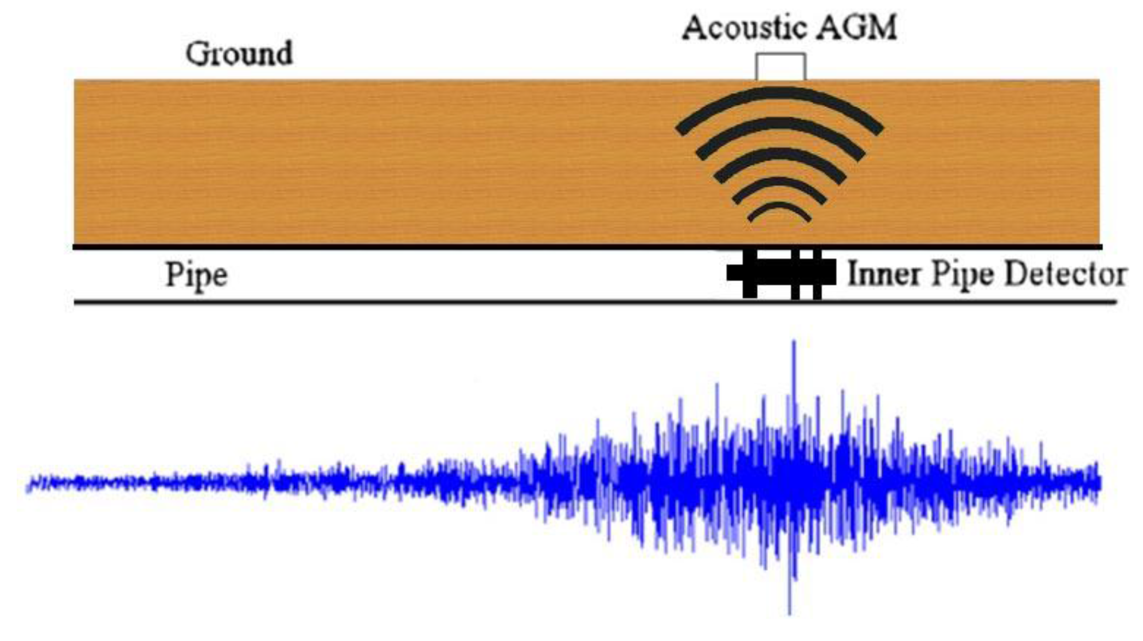
- Ultra-low frequency electromagnetic field positioning technology is the most widely used technology. Figure 12 gives a common example. Because of the extremely low frequency of the electromagnetic field, the electromagnetic field has good penetration through metal, soil and air, so it is widely used in the detection of defects in oil/gas pipelines.

3.4. Quantitative Analysis of the MFL
3.5. Statistical Identification of Defect Length, Width and Height
3.6. 3D Finite Element Neural Network Method

4. Expert System
5. Future Developments
6. Conclusions
- MFL is the most popular method of pipeline nondestructive testing technique which uses a magnetic sensitive element to detect the defects on both internal and external surfaces. Application of numerical calculation methods has made great progress in the theoretical research, and the relationship between the shape of the defect and the leakage magnetic field is well established. But there are many limitations when put into the practice.
- Because of their mature manufacturing process, favorable stability and temperature characteristics, Hall sensors are the first choice for measurement of leakage magnetic fields.
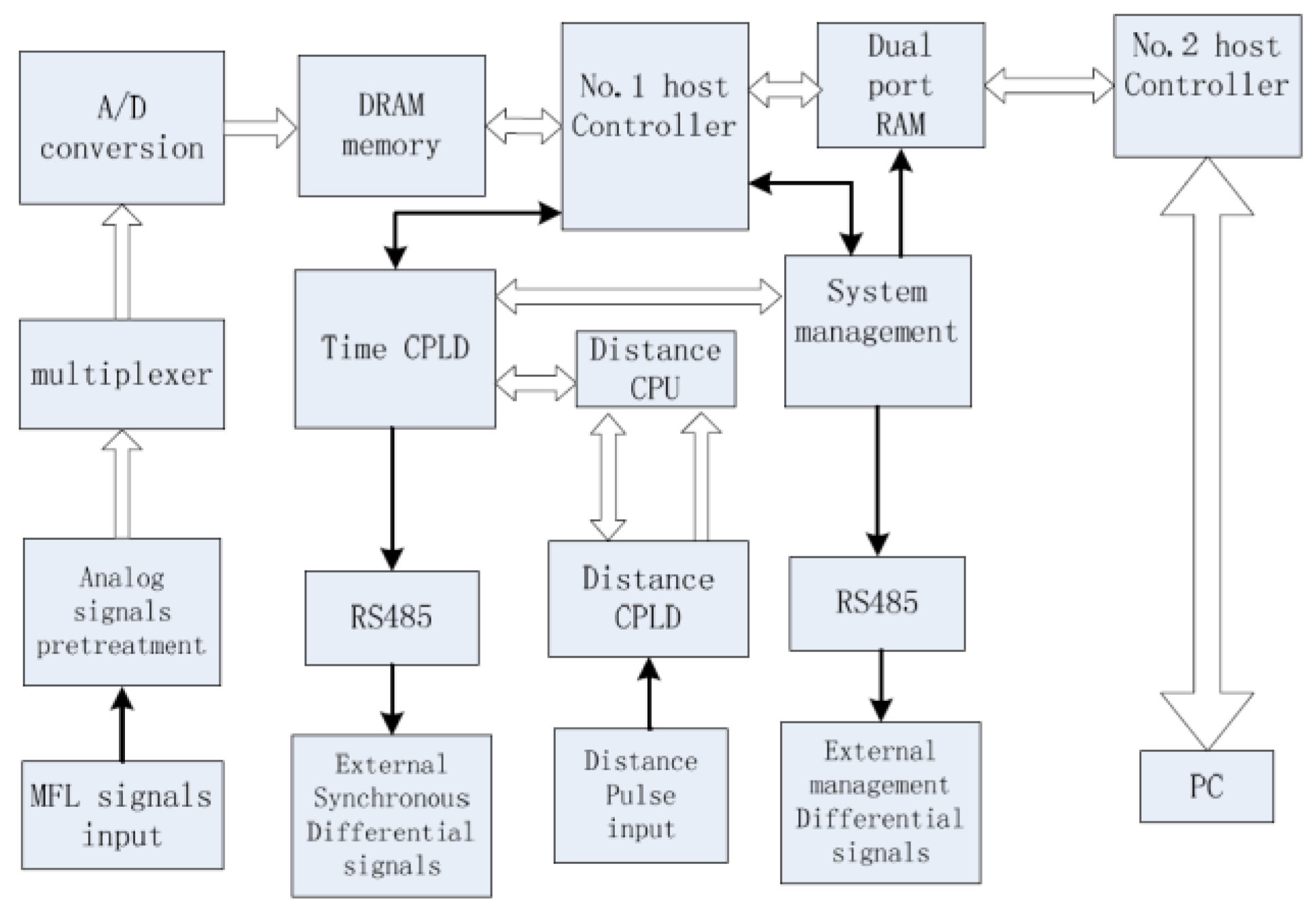
- The processing of the detection signal includes data acquisition, storage and compression and noise reduction.
- Ground marking systems are used to determine the position of the detector and facilitate pipeline excavation.
- Statistical identification methods are used to establish the relationship between the defect shape parameter and magnetic flux leakage signals. A 3D finite element neural network is convenient for hardware and software based on the realization of parallel computing.
- Expert systems are an important aspect of artificial intelligence work. They gives the analysis result according to the knowledge and experience of the experts in the field, but nowadays the evaluation relies on too much this experience.
Conflicts of Interest
References
- Rott, W.; Schmidt, K.; Blitz, G.; Magerstadt, M. A novel pipe-cap system for corrosion protection and security. J. Pipeline Eng. 2012, 11, 124–130. [Google Scholar]
- Kim, H.M.; Rho, Y.W.; Yoo, H.R.; Cho, S.H.; Kim, D.K.; Koo, S.J.; Park, G.S. A study on the measurement of axial cracks in the magnetic flux leakage NDT system. In Proceedings of the 8th IEEE International Conference on Automation Science and Engineering, Seoul, Korea, 20–24 August 2012; pp. 624–629.
- Wagner, R.; Goncalves, O.; Demma, A.; Lowe, M. Guided wave testing performance studies: comparison with ultrasonic and magnetic flux leakage pigs. Non-Destruct. Test. Cond. Monit. 2013, 55, 187–196. [Google Scholar] [CrossRef]
- Qi, J. Experimental study of interference factors and simulation on oil-gas pipeline magnetic flux leakage density signal. In Proceedings of the 2007 IEEE International Conference on Mechatronics and Automation, Harbin, China, 5–8 August 2007; pp. 3652–3656.
- Amineh, R.K.; Nikolova, N.K.; Reilly, J.P.; Hare, J.R. Characterization of surface breaking cracks using one tangential component of magnetic leakage field. IEEE Trans. Magn. 2008, 44, 516–524. [Google Scholar] [CrossRef]
- Loskutov, V.E.; Matvienko, A.F.; Patramanskii, B.V.; Shcherbinin, V.E. The magnetic method for in-tube nondestructive testing of gas and oil pipelines: The past and the present. Rus. J. Non-Destruct. Test. 2006, 42, 493–504. [Google Scholar] [CrossRef]
- Chen, J.; Feng, Q.S.; Wang, F.X.; Zhang, H.L.; Song, H.C. Research on burst tests of pipeline with spiral weld defects. In Proceedings of the 9th International Pipeline Conference, Calgary, AL, Canada, 24–28 September 2012; pp. 53–60.
- Ma, Y.L.; Li, L. Research on internal and external defect identification of drill pipe based on weak magnetic inspection. Insight Non-Destruct. Test. Cond. Monit. 2014, 56, 31–34. [Google Scholar]
- Hasanzadeh, R.R.; Sadeghi, S.H.; Ravan, M.; Moghaddamjoo, A.R.; Moini, R. A fuzzy alignment approach to sizing surface cracks by the AC field measurement technique. NDT&E Int. 2011, 44, 75–83. [Google Scholar]
- Ma, W.; Zhang, X.M.; Liu, S.C. Analysis on difference between Chinese and Russian oil and gas pipeline operation standards. Oil Gas Storage Transp. 2013. [Google Scholar] [CrossRef]
- Kim, H.M.; Park, G.S. A Study on the Estimation of the Shapes of Axially Oriented Cracks in CMFL Type NDT System. IEEE Trans. Magn. 2014, 50. [Google Scholar] [CrossRef]
- Salama, M.M.; Nestleroth, B.J.; Maes, M.A.; Dash, C. Characterization of the Uncertainties in the Inspection Results of Ultrasonic Intelligent Pigs. In Proceedings of the 32nd International Conference on Ocean, Offshore and Arctic Engineering, Nantes, France, 9–14 June 2013.
- Helifa, B.; Oulhadj, A.; Benbelghit, A.; Lefkaier, I.K.; Boubenider, F.; Boutassouna, D. Detection and measurement of surface cracks in ferromagnetic materials using eddy current testing. NDT&E Int. 2006, 39, 384–390. [Google Scholar]
- David, M.; Phil, T. ILI of New Rehabilitation System uses Axial and Spiral Field MFL. Available online: http://www.pipelineandgasjournal.com/ili-new-rehabilitation-system-uses-axial-and-spiral-field-mfl (accessed on 8 December 2015).
- Qing, P.J.; Zhi, J.A. Internal and external defect identification of pipelines using the PSO-SVM method. Insight Non-Destruct. Test. Cond. Monit. 2015, 57, 85–91. [Google Scholar]
- Wang, Y.D.; Xu, Y.T.; Wang, B.; Ding, S.B.; Xu, J.L.; Zheng, M.L. Research on metal atmospheric storage tank inspection method for standard in China. In Proceedings of the ASME 2009 Pressure Vessels and Piping Division Conference, Prague, Czech Republic, 26–30 July 2009; pp. 447–452.
- Liang, C.; Xing, L.; Xun, B.L.; Zuo, Y.H. Signal extraction using ensemble empirical mode decomposition and sparsity in pipeline magnetic flux leakage nondestructive evaluation. Rev. Sci. Instrum. 2009, 80. [Google Scholar] [CrossRef]
- Kopp, G.; Willems, H. Sizing limits of metal loss anomalies using tri-axial MFL measurements: A model study. NDT&E Int. 2013, 55, 75–81. [Google Scholar]
- Doubov, A.A.; Kouleev, V.G. Inspection of welding defects with metal magnetic memory method. Welded Pipe Tube 2008, 31, 44–48. [Google Scholar]
- Li, Y.; Tian, G.Y.; Ward, S. Numerical simulations on electromagnetic NDT at high speed. Insight Non-Destruct. Test. Cond. Monit. 2006, 48, 103–108. [Google Scholar] [CrossRef]
- Safizadeha, M.S.; Azizzadeh, T. Corrosion detection of internal pipeline using NDT optical inspection system. NDT&E Int. 2012, 52, 144–148. [Google Scholar]
- Du, Z.Y.; Ruan, J.J. 3-D FEM Simulation of Velocity Effects on Magnetic Flux Leakage Testing Signals. IEEE Trans. Magn. 2008, 44, 1642–1645. [Google Scholar]
- Yong, Y.Z.; Zhong, F.; Chong, W. A fast method for rectangular crack sizes reconstruction in magnetic flux leakage testing. NDT&E Int. 2009, 42, 369–375. [Google Scholar]
- Keshwani, R.T. Analysis of Magnetic Flux Leakage Signals of Instrumented Pipeline Inspection Gauge using Finite Element Method. IETE J. Res. 2009, 55, 73–82. [Google Scholar] [CrossRef]
- Pechenkov, A.N.; Shcherbinin, V.E.; Smorodinskiy, J.G. Analytical model of a pipe magnetization by two parallel linear currents. NDT&E Int. 2011, 44, 718–720. [Google Scholar]
- Boateng, A.; Danso, K.A.; Dagadu, C.K. Non-Destructive Evaluation of Corrosion on Insulated Pipe using Double Wall Radiographic Technique. Chem. Mater. Res. 2013, 3, 73–83. [Google Scholar]
- Sun, Y.H.; Kang, Y.H.; Qiu, C. A new NDT method based on permanent magnetic field perturbation. NDT&E Int. 2011, 44, 1–7. [Google Scholar]
- Kim, H.M.; Yoo, H.R.; Rho, Y.W.; Park, G.S. Detection method of cracks by using magnetic fields in underground pipeline. In Proceedings of the 10th International Conference on Ubiquitous Robots and Ambient Intelligence, Jeju, Korea, 31 October–2 November 2013.
- Sushant, M.D.; Fathi, H.G.; Roderic, K.S. Dipole Modeling of Magnetic Flux Leakage. IEEE Trans. Magn. 2009, 45, 1959–1965. [Google Scholar]
- Saha, S.; Mukhopadhyay, S.; Mahapatra, U.; Bhattacharya, S.; Srivastava, G.P. Empirical structure for characterizing metal loss defects from radial magnetic flux leakage signal. NDT&E Int. 2010, 43, 507–512. [Google Scholar]
- Chen, J.J.; Huang, S.L.; Zhao, W. Equivalent MFL model of pipelines for 3-D defect reconstruction using simulated annealing inversion procedure. Int. J. Appl. Electromagn. Mech. 2015, 47, 551–561. [Google Scholar]
- Li, Y.; Wilson, J.; Tian, G.Y. Experiment and simulation study of 3D magnetic field sensing for magnetic flux leakage defect characterization. NDT&E Int. 2007, 40, 179–184. [Google Scholar]
- Xing, L.; Liang, C.; Xiao, H.Z. FEA of Pipeline Magnetic Flux Leakage NDE. In Proceedings of the 2009 IEEE International Conference on Applied Superconductivity and Electromagnetic Devices, Chengdu, China, 25–27 September 2009.
- Hall, J.P.; Moses, A.J. FEM modelling techniques of magnetic flux leakage-type NDT for ferromagnetic plate inspections. J. Magn. Magn. Mater. 2006, 304, 790–793. [Google Scholar]
- Hari, K.C.; Nabi, M.; Kulkarni, S.V. Improved FEM model for defect-shape construction from MFL signal by using genetic algorithm. Sci. Meas. Technol. 2007, 1, 196–200. [Google Scholar] [CrossRef]
- Chao, X.; Chang, L.W.; Feng, Z.J.; Xi, C.Y. Finite-Element Neural Network-Based Solving 3-D Differential Equations in MFL. IEEE Trans. Magn. 2012, 48, 4747–4756. [Google Scholar] [CrossRef]
- Sun, Y.H.; Kang, Y.H. Magnetic mechanisms of magnetic flux leakage nondestructive testing. Appl. Phys. Lett. 2013, 138. [Google Scholar] [CrossRef]
- Amineh, R.; Koziel, S.; Nikolova, N.; Bandler, J.; Reilly, J. A space mapping methodology for defect characterization from magnetic flux leakage measurements. IEEE Trans. Magn. 2008, 44, 2058–2065. [Google Scholar] [CrossRef]
- Du, Z.; Ruan, J. Improvement of magnetic flux leakage equipment for oil pipe testing. Nondestruct. Inspect. 2007, 2007, 560–564. [Google Scholar]
- Xun, B.L.; Xiang, L.; Liang, C.; Pei, F.; Hai, D.W.; Zuo, Y.H. Numerical simulation and experiments of magnetic flux leakage inspection in pipeline steel. J. Mech. Sci. Technol. 2009, 23, 109–113. [Google Scholar]
- Joshi, A.; Udpa, L.; Udpa, S.; Tamburrino, A. Adaptive wavelets for characterizing magnetic flux leakage signals from pipeline inspection. IEEE Trans. Magn. 2006, 42, 3168–3170. [Google Scholar] [CrossRef]
- Isabel, C.P.; Jorge, H.A.; Gerd, D. Simulation for magnetic flux leakage signal interpretation: A FE-approach to support in-line magnetic pipeline pigging. In Proceedings of the 2014 IEEE Far East Forum of Nondestructive Evaluation/Testing, Chengdu, China, 20–23 June 2014; pp. 349–353.
- Li, X.; Chen, L.; Huang, Z.Y. Steel Pipeline Testing Using Magnetic Flux Leakage Method. Industrial Technology. In Proceedings of the 2008 IEEE International Conference on Industrial Technology, Chengdu, China, 21–24 April 2008; pp. 1–4.
- Xue, Y.W.; Xin, J.W.; Jiang, X.; Hong, B. Study on the lift-off effect on MFL signals with magnetic circuit model and 3D FEM. Insight Non-Destruct. Test. Cond. Monit. 2012, 54, 505–510. [Google Scholar]
- Feng, J.; Zhang, J.F.; Lu, S.X.; Wang, H.Y.; Ma, R.Z. Three-axis magnetic flux leakage in-line inspection simulation based on finite-element analysis. Chin. Phys. B 2013, 1, 531–536. [Google Scholar] [CrossRef]
- Xu, F.X.; Wang, X. Inspection method of cable-stayed bridge using magnetic flux leakage detection: principle, sensor design and signal processing. J. Mech. Sci. Technol. 2012, 26, 661–669. [Google Scholar] [CrossRef]
- Zhen, N.W.; Hua, G.Z.; Jin, H.L. A PCA and ELM Based Adaptive Method for Channel Equalization in MFL Inspection. Math. Probl. Eng. 2014, 22. [Google Scholar] [CrossRef]
- Ameet, J.; Lalita, U.; Satish, U. Use of higher order statistics for enhancing magnetic flux leakage pipeline inspection data. Int. J. Appl. Electromagn. Mech. 2007, 25, 357–362. [Google Scholar]
- Wei, D.Q.; Hong, B.X. Design of High-speed Data Collecting System for Pipeline Magnetic Flux Leakage Inspection. In Proceedings of the 5th International Conference on Machine Vision, Wuhan, China, 20–21 April 2012.
- Tehranchi, M.M.; Ranjbaran, M.; Eftekhari, H. Double core giant magneto-impedance sensors for the inspection of magnetic flux leakage from metal surface cracks. Sens. Actuators A Phys. 2011, 170, 55–61. [Google Scholar] [CrossRef]
- Wilson, J.W.; Kaba, M.; Tian, G.Y.; Licciardi, S. Feature extraction and integration for the quantification of PMFL data. Nondestruct. Test. Eval. 2010, 25, 101–109. [Google Scholar] [CrossRef]
- Espina-Hernandez, J.W.; Hallen, J.M. Influence of Remanent Magnetization on Pitting Corrosion in Pipeline Steel. In Proceedings of the 8th International Pipeline Conference, Calgary, AL, Canada, 27 September–1 October 2010; pp. 565–572.
- Gloriaa, N.S.; Areiza, M.L. Development of a magnetic sensor for detection and sizing of internal pipeline corrosion defects. NDT&E Int. 2009, 42, 669–677. [Google Scholar]
- Li, J.Y.; Feng, M.M.; Song, W.G. Lossless Compression of Pipeline Magnetic Flux Leakage Inspection Data Based on Region of Interest. In Proceedings of the 6th World Congress on Intelligent Control and Automation, Dalian, China, 21–23 June 2006.
- Nara, T.; Fujieda, M.; Gotoh, Y. Non-destructive inspection of ferromagnetic pipes based on the discrete Fourier coefficients of magnetic flux leakage. J. Appl. Phys. 2014, 115. [Google Scholar] [CrossRef]
- Kathirmani, S.; Tangirala, A.K.; Saha, S. Online data compression of MFL signals for pipeline inspection. NDT&E Int. 2012, 50, 1–9. [Google Scholar]
- Ke, M.Y.; Liao, P.; Song, X.C. Real-time Data Mining in Magnetic Flux Leakage Detecting in Boiler Pipeline. In Proceedings of the International Conference on Digital Manufacturing & Automation, Changsha, China, 18–20 December 2010.
- Tehranchi, M.M.; Hamidi, S.M.; Eftekhari, H.; Karbaschi, M.; Ranjbaran, M. The inspection of magnetic flux leakage from metal surface cracks by magneto-optical sensors. Sens. Actuators A Phys. 2011, 172, 365–368. [Google Scholar] [CrossRef]
- Song, X.C.; Xue, L.; Xu, Z.W. The simulation and experimental analysis of the MFL for cracks inspection in pipelines under mechanics-magnetic coupling. In Proceedings of the 7th International Symposium on Precision Engineering Measurements and Instrumentation, Lijiang, China, 7–11 August 2011.
- Wang, P.; Gao, Y.L.; Tian, G.Y.; Wang, H.T. Velocity effect analysis of dynamic magnetization in high speed magnetic flux leakage inspection. NDT&E Int. 2014, 64, 7–12. [Google Scholar]
- Tindall, L.M.; Race, J.M.; Dawson, J. Investigating the relative severity of dents in pipelines based on magnetic flux leakage inspection data. In Proceedings of the 7th International Pipeline Conference, Calgary, AL, Canada, 29 September–3 October 2008.
- Li, Y.; Wang, D.; Sun, L.Y. A novel algorithm for acoustic above ground marking based on function fitting. Measurement 2013, 46, 2341–2347. [Google Scholar] [CrossRef]
- Mukherjee, D.; Saha, S.; Mukhopadhyay, S. An adaptive channel equalization algorithm for MFL signals. NDT&E Int. 2012, 45, 111–119. [Google Scholar]
- Mukhopadhyay, S.; Tiwari, A.P. Characterization of NDT signals: Reconstruction from wavelet transform maximum curvature presentation. Signal Process. 2010, 90, 261–268. [Google Scholar] [CrossRef]
- Saranya, R.; Jackson, D.; Abudhahir, A.; Chermakani, N. Comparison of Segmentation Techniques for Detection of Defects in Non-Destructive Testing Images. In Proceedings of the 2014 International conference on Electronics and Communication Systems, Coimbatore, India, 13–14 February 2014; pp. 1–6.
- Mojtaba, R.K.; Farshad, S.; Babak, N.A.; Majid, N.A. Defect Detection and Width Estimation in Natural Gas Pipelines using MFL Signals. In Proceedings of the 9th Asian Control conference, Istanbul, Turkey, 23–26 June 2013; pp. 1–6.
- Misron, N.; Shin, N.W.; Shafie, S.; Marhaban, M.H.; Mailah, N.F. A mobile ferromagnetic shape detection sensor using a hall sensor array and magnetic imaging. Sensors 2011, 11, 10474–10489. [Google Scholar] [CrossRef] [PubMed]
- Abdellatif, B.; Mohammed, S.H.; Khaled, A. Design of an oil pipe inner surface inspection system. In Proceedings of the 2011 IEEE GCC Conference and Exhibition, Dubai, United Arab Emirates, 19–22 February 2011.
- Mojtaba, R.K.; Babak, N.A.; Majid, N.; Farshad, S.; Maisam, M.B. Detection of Natural Gas Pipeline Defects using Magnetic Flux Leakage Measurements. In Proceedings of the 21st Iranian Conference on Electrical Engineering, Mashhad, Iran, 14–16 May 2013; pp. 1–6.
- Han, W.H.; Shen, X.H.; Xu, J.; Wang, P.; Tian, G.Y.; Wu, Z.Y. Fast Estimation of Defect Profiles from the Magnetic Flux Leakage Signal Based on a Multi-Power Affine Projection Algorithm. Sensors 2014, 14, 16454–16466. [Google Scholar] [CrossRef] [PubMed]
- Fang, Y.; Li, Z.; Su, Y. Feature Extraction of Pipeline Crack Defect Signals with MMM Testing Based on Wavelet packet Frequency Bands Energy. In Proceedings of the 2009 International Conference on Information Technology and Computer Science, Kiev, Ukraine, 25–26 July 2009; pp. 277–280.
- Feng, Z.J.; Chang, L.W.; Xian, Z.Z.; Song, S.H. LS-SVMs-based reconstruction of 3-D defect profile from magnetic flux leakage signals. Insight Non-Destruct. Test. Cond. Monit. 2007, 49, 516–520. [Google Scholar]
- Khodayari-Rostamabad, A.; Reilly, J.P.; Nikolova, N.K.; Hare, J.R.; Pasha, S. Machine Learning Techniques for the Analysis of Magnetic Flux Leakage Images in Pipeline Inspection. IEEE Trans. Magn. 2009, 45, 3073–3084. [Google Scholar] [CrossRef]
- Sophian, A.; Tian, G.Y.; Zairi, S. Pulsed Magnetic Flux Leakage Techniques for Crack Detection and Characterization. Sens. Actuators A Phys. 2006, 125, 186–191. [Google Scholar] [CrossRef]
- Le, M.; Vu, H.; Kim, J.; Angani, C.S.; Lee, J. Quantitative evaluation of corrosion in a thin small-bore piping system using bobbin-type magnetic camera. J. Nondestruct. Eval. 2014, 33, 74–81. [Google Scholar] [CrossRef]
- Chen, J.Z.; Lin, L.; Shi, J.N. Magnetic Flux Leakage Detection Technology for Well Casing on Neural Network. In Proceedings of the International Symposium on Intelligent Information Technology Application Workshops, Shanghai, China, 21–22 December 2008; pp. 1085–1088.
- Yang, L.; Liu, G.; Zhang, G.; Gao, S. Oil-gas pipeline magnetic flux leakage testing defect reconstruction based on support vector machine. In Proceedings of the Second International Conference on Intelligent Computation Technology and Automation, Changsha, China, 10–11 October 2009; pp. 395–398.
- Carvalho, A.A.; Silva, R.R. Pattern Recognition Techniques Applied to the Detection and Classification of Welding Defects by Magnetic Testing. Res. Nondestruct. Eval. 2010, 21, 91–111. [Google Scholar] [CrossRef]
- Ma, Z.L.; Liu, H.D. Pipeline defect detection and sizing based on MFL data using immune RBF neural networks. In Proceedings of the 2007 IEEE Congress on Evolutionary Computation, Singapore, 25–28 September 2007; pp. 3399–3403.
- Yu, H.C.; Tian, Y. The Management of Inner Inspection Data of Pipelines. Oil Gas Storage Transp. 2012, 8, 569–571. [Google Scholar]
- Zhang, Y.K. Development of the Above Ground Mark System for Pipelines Inspection Using a Magnetic Flux Leakage Detector. Ph.D. Thesis, Tianjin University, Tianjin, China, 2006. [Google Scholar]
- Chen, J.J.; Huang, S.L.; Zhao, W. Three-dimensional defect reconstruction from magnetic flux leakage signals in pipeline inspection based on a dynamic taboo search procedure. Insight Non-Destruct. Test. Cond. Monit. 2014, 56, 535–540. [Google Scholar] [CrossRef]
- Ameet, J. Wavelet transform and neural network based 3D defect characterization using magnetic flux leakage. Int. J. Appl. Electromagn. Mech. 2008, 28, 149–153. [Google Scholar]
- Sun, L.Y.; Li, Y.B.; Du, G.; Wang, W.K.; Zhang, Y.K. Modification design of high-precision above ground marking system. In Proceedings of the 2010 Chinese Control and Decision Conference, Xuzhou, China, 26–28 May 2010; pp. 531–535.
- Goller, C.; Simek, J.; Ludlow, J. Multiple data set Ili for mechanical damage assessment. In Proceedings of the 9th International Pipeline Conference, Calgary, AL, Canada, 24–28 September 2012; pp. 79–87.
- Zakaria, Z.; Badri-Mansor, M.S.; Jahidin, A.H.; Azlan, M.S.Z.; Rahim, R.A. Simulation of Magnetic Flux Leakage (MFL) Analysis Using FEMM Software. In Proceedings of the 2010 IEEE Symposium on Industrial Electronics and Applications, Penang, Malaysia, 3–5 October 2010; pp. 481–486.
- Chao, X.; Wang, C.L. Reconstruction of 3D defect profiles from the MFLT signals by using a radial wavelet basis function neural network iterative model. Insight Non-Destruct. Test. Cond. Monit. 2012, 54, 138–143. [Google Scholar]
- Babbar, V.; Bryne, J.; Clapham, L. Mechanical Damage Detection Using Magnetic Flux Leakage Tools: Modelling the Effect of Dent Geometry and Stresses. NDT&E Int. 2005, 38, 471–477. [Google Scholar]
- Jandu, C.; Taylor, M.; Narikotte, S.J. API 579 level 3 assessment of dents using high-resolution ILI data. In Proceedings of the 30th International Conference on Ocean, Offshore and Arctic Engineering, Rotterdam, The Netherlands, 19–24 June 2011; pp. 1001–1007.
- Miller, S.; Clouston, S. Optimizing magnetic flux leakage inspection sizing model performance using high-resolution non-destructive examination data. J. Pipeline Eng. 2012, 11, 117–123. [Google Scholar]
- Purnachandra, R.B.; Thirunavukkarasu, S.; Mahadevan, S.; Mukhopadhyay, C.K.; Jayakumar, T. Development of magnetic flux leakage technique for examination of steam generator tubes of prototype fast breeder reactor. Ann. Nucl. Energy 2015, 83, 57–64. [Google Scholar]
- Feng, Q.S.; Sutherland, J.; Gu, B.; Wei, Y.; Tao, C. Evolution of triax magnetic flux leakage inspection for mitigation of spiral weld anomalies. In Proceedings of the 8th International Pipeline Conference, Calgary, AL, Canada, 27 September–1 October 2010; pp. 209–216.
- Williamson, T.D. MFL Inspection of European Line Fuel Pipeline. Pipeline Gas J. 2012, 239, 72. [Google Scholar]
- Thomas, D.M. A Magnetic Flux Leakage NDE System for Candor Feeder Pipes. Ph.D. Thesis, Queen’s University, Kingston, ON, Canada, 2010. [Google Scholar]
- Brockhaus, S.; Lindner, H.; Steinvoorte, T.; Hennerkes, H. Record Inspection of the World’s Longest Subsea Gas Pipeline. Pipeline Gas J. 2010, 237, 86–88. [Google Scholar]
- Jiang, Q. Study of Underground Oil-Gas Pipeline Corrosion Pits Estimation Based on MFL Inspection Method. J. Test. Eval. 2015. [Google Scholar] [CrossRef]
- Dutta, S.; Ghorbel, F.; Stanley, R. Simulation and Analysis of Magnetic Flux Leakage. IEEE Trans. Magn. 2007, 45, 1966–1972. [Google Scholar] [CrossRef]
- Martin, K.; Thomas, B. Pipeline inspection with the high resolution emitili-tool: Report on full-scale testing and field trials. In Proceedings of the 6th International Pipeline Conference, Calgary, AL, Canada, 25–29 September 2006; pp. 235–241.
- Mao, B.Y.; Lu, Y.; Wu, P.; Mao, B.Z.; Li, P.F. Signal processing and defect analysis of pipeline inspection applying magnetic flux leakage methods. Intel. Serv. Robot. 2014, 4, 203–209. [Google Scholar] [CrossRef]
- Sushant, M.D.; Fathi, H.G. Magnetic flux leakage sensing: current practices and mathematical analysis. In Proceedings of the 2007 ASME International Mechanical Engineering Congress and Exposition, Seattle, WA, USA, 11–15 November 2007; pp. 981–989.
- Mazumdar, A.; Asada, H.H. An under actuated, magnetic-foot robot for steel bridge inspection. Mech. Robot. 2010, 2. [Google Scholar] [CrossRef]
- Geuzaine, C.; Remacle, J.-F. Gmsh: A three-dimensional finite element mesh generator with built-inpre-and post-processing facilities. Eng. Comput. Technol. 2009. [Google Scholar] [CrossRef]
- Wei, L.; Xin, A.Y.; Guo, M.C.; Xiao, K.Y.; Jiu, H.G. A feed-through ACFM probe with sensor array for pipe string cracks inspection. NDT&E Int. 2014, 67, 17–23. [Google Scholar]
- Herbert, W.; Beate, J.; Thorsten, S.; Alfred, B.; Frank, N. A new ILI tool for metal loss inspection of gas pipelines using a combination of ultrasound, eddy current and MFL. In Proceedings of the 8th International Pipeline Conference, Calgary, AL, Canada, 27 September–1 October 2010; pp. 557–564.
- Richard, N. Can Technology Chart a Safer Future for Pipelines? Pipelines Gas J. 2011, 238, 34–38. [Google Scholar]
- Mamdouh, M.S.; Bruce, J.N.; Marc, A.M.; Carlos, R.; Dave, B. Characterization of the accuracy of the MFL pipeline inspection tools. In Proceedings of the 31st International Conference on Ocean, Offshore and Arctic Engineering, Rio de Janeiro, Brazil, 1–6 July 2012; pp. 247–251.
- Ireland, R.C.; Torres, C.R. Finite element modeling of a circumferential magnetizer. Sens. Actuators A Phys. 2006, 129, 1–3. [Google Scholar] [CrossRef]
- Lin, S.W.; Ying, K.C.; Chen, S.C. Particle swarm optimization for parameter determination and feature selection of support vector machines. Expert Syst. Appl. 2008, 35, 1817–1824. [Google Scholar] [CrossRef]
- Sheng, W.F.; Zhang, X.B. Fault diagnosis of power transformer based on support vector machine with genetic algorithm. Expert Syst. Appl. 2009, 36, 11352–11357. [Google Scholar]
- Lynch, A.J. Magnetic Flux Leakage Robotic Pipe Inspection: Internal and External Methods. M.Sc Thesis, Rice University, Houston, TX, USA, 2009. [Google Scholar]
- Williamson, T.D. New 48-inch Gas Magnetic Flux Leakage Inspection Tool. Pipeline Gas J. 2010, 237, 75. [Google Scholar]
- Li, X.M.; Ding, H.S.; Bai, S.W. Research on the stress-magnetism effect of ferromagnetic materials based on three-dimensional magnetic flux leakage testing. NDT&E Int. 2014, 62, 50–54. [Google Scholar]
- Williamson, T.D. Introduces Spiral Magnetic Flux Leakage Inspection Tool. Pipeline Gas J. 2011, 238, 72. [Google Scholar]
© 2015 by the authors; licensee MDPI, Basel, Switzerland. This article is an open access article distributed under the terms and conditions of the Creative Commons by Attribution (CC-BY) license (http://creativecommons.org/licenses/by/4.0/).
Share and Cite
Shi, Y.; Zhang, C.; Li, R.; Cai, M.; Jia, G. Theory and Application of Magnetic Flux Leakage Pipeline Detection. Sensors 2015, 15, 31036-31055. https://doi.org/10.3390/s151229845
Shi Y, Zhang C, Li R, Cai M, Jia G. Theory and Application of Magnetic Flux Leakage Pipeline Detection. Sensors. 2015; 15(12):31036-31055. https://doi.org/10.3390/s151229845
Chicago/Turabian StyleShi, Yan, Chao Zhang, Rui Li, Maolin Cai, and Guanwei Jia. 2015. "Theory and Application of Magnetic Flux Leakage Pipeline Detection" Sensors 15, no. 12: 31036-31055. https://doi.org/10.3390/s151229845