Three-Dimensional Object Motion and Velocity Estimation Using a Single Computational RGB-D Camera


Abstract
: In this paper, a three-dimensional (3D) object moving direction and velocity estimation method is presented using a dual off-axis color-filtered aperture (DCA)-based computational camera. Conventional object tracking methods provided only two-dimensional (2D) states of an object in the image for the target representation. The proposed method estimates depth information in the object region from a single DCA camera that transforms 2D spatial information into 3D model parameters of the object. We also present a calibration method of the DCA camera to estimate the entire set of camera parameters for a practical implementation. Experimental results show that the proposed DCA-based color and depth (RGB-D) camera can calculate the 3D object moving direction and velocity of a randomly moving object in a single-camera framework.1. Introduction
Object tracking is a very popular research topic in the computer vision field because of its wide applications in video surveillance systems, intelligent driver assistant systems, robot vision, etc. [1,2]. Conventional object tracking methods provided only two-dimensional (2D) states of an object in the image and therefore cannot deal with the occlusion and depth-related problems. For solving these problems, estimation of three-dimensional (3D) depth information has been intensively studied for the past several decades [3–6].
The traditional approach to 3D image acquisition or depth estimation involves the use of two cameras that capture two images of the same scene from different viewpoints [7,8]. Despite many advantages, the stereo vision system has a fundamental limitation that highly accurate calibration is required for both cameras. In addition, stereo cameras require both calibration and rectification steps for the alignment of two cameras. However, even after completion of the two steps, the rectification step should be performed again, if the stereo camera is influenced by various external factors that break the alignment between two cameras. As an alternative approach, Panasonic's LUMIX G 12.5 mm F12 lens can acquire two images with different viewpoints by dividing the imaging sensor into two regions. Although this system mimics the stereo vision in a single-camera framework, the reduced resolution is the fundamental disadvantage.
Another single camera-based depth estimation approach is the pupil plane coding method that modifies an aperture of a lens for coding geometric depth information into the image [9]. Recently, three apertures covered with red, green and blue filters have been used for the same purpose [10], where three color-filtered apertures (TCA) generate color shifts among channels depending on the distance of an object. Kim et al. proposed a multifocusing image restoration algorithm using the distance estimation in the color shifted image using the TCA [11]. Lee et al. proposed a simultaneous object tracking and depth estimation system using the TCA camera [12]. However, these TCA-based methods produce redundant pairs of disparity vectors and do not establish the theoretically complete relationship between color shifting and the real distance. Lee et al. proposed a novel configuration of dual off-axis color-filtered apertures (DCA) to remove the disparity redundancy of the color shifting vectors and to increase the size of an individual aperture to receive more incoming light [13]. The mathematical model of the DCA configuration with the relationship between color shifting values and the actual distance of the object were proposed in [14].
In this paper, we present a novel 3D object moving direction and velocity estimation method for robust object tracking using a DCA-based computational RGB-D camera. The incremental learning-based approach [15] is used for object tracking from the DCA camera, and the color shifting value (CSV), which is related to the distance of the object, is estimated in the region of the tracked object. The states of the object at the image coordinate are then transformed into the 3D parameters of the object using the estimated CSV. Finally, the direction and velocity of a moving 3D object are simultaneously calculated while tracking the object. We also present a calibration method of the DCA camera to estimate the entire set of camera parameters for real applications. Although this work shares the concept of multiple, color-filtered apertures in the previous work [11–14], the original contribution includes: (i) the incremental learning-based object tracking algorithm that is optimized for the DCA camera system; (ii) single camera-based simultaneous 3D object moving direction and velocity estimation; and (iii) a novel calibration method that can be used for a DCA camera system.
The paper is organized as follows. Section 2 presents the background of the DCA camera, and Sections 3 and 4 describe the object moving direction and velocity estimation for tracking and the DCA camera calibration, respectively. Experimental results are provided in Section 5, and Section 6 concludes the paper.
2. Dual Off-Axis Color-Filtered Aperture-Based Camera
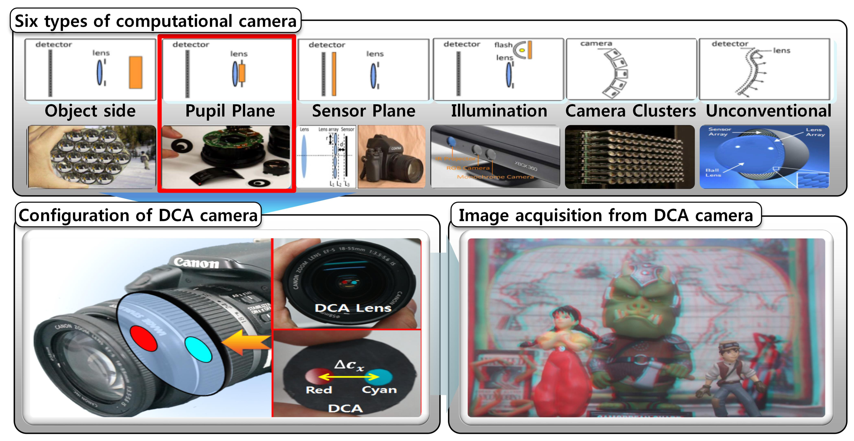
Recently, computational imaging systems have been widely used for obtaining additional information, while traditional imaging systems only acquire intensity and color information. A computational imaging system projects rays, which is altered by specially-designed optics, in the light field of the scene onto the image sensor using novel optics and the correspondingly developed image processing algorithms. These systems can produce a new type of image that is potentially useful for re-focusing, scene segmentation and 3D computer vision. Computational imaging systems can be broadly classified into six categories, as shown in Figure 1 [9].
The pupil plane coding places a specially designed pattern at the aperture in front of the lens to easily configure the computational camera for depth information. By incorporating the concept of pupil plane coding, we design a novel computational imaging system by simply inserting an appropriately resized DCA into any general optical system in the single-camera framework.
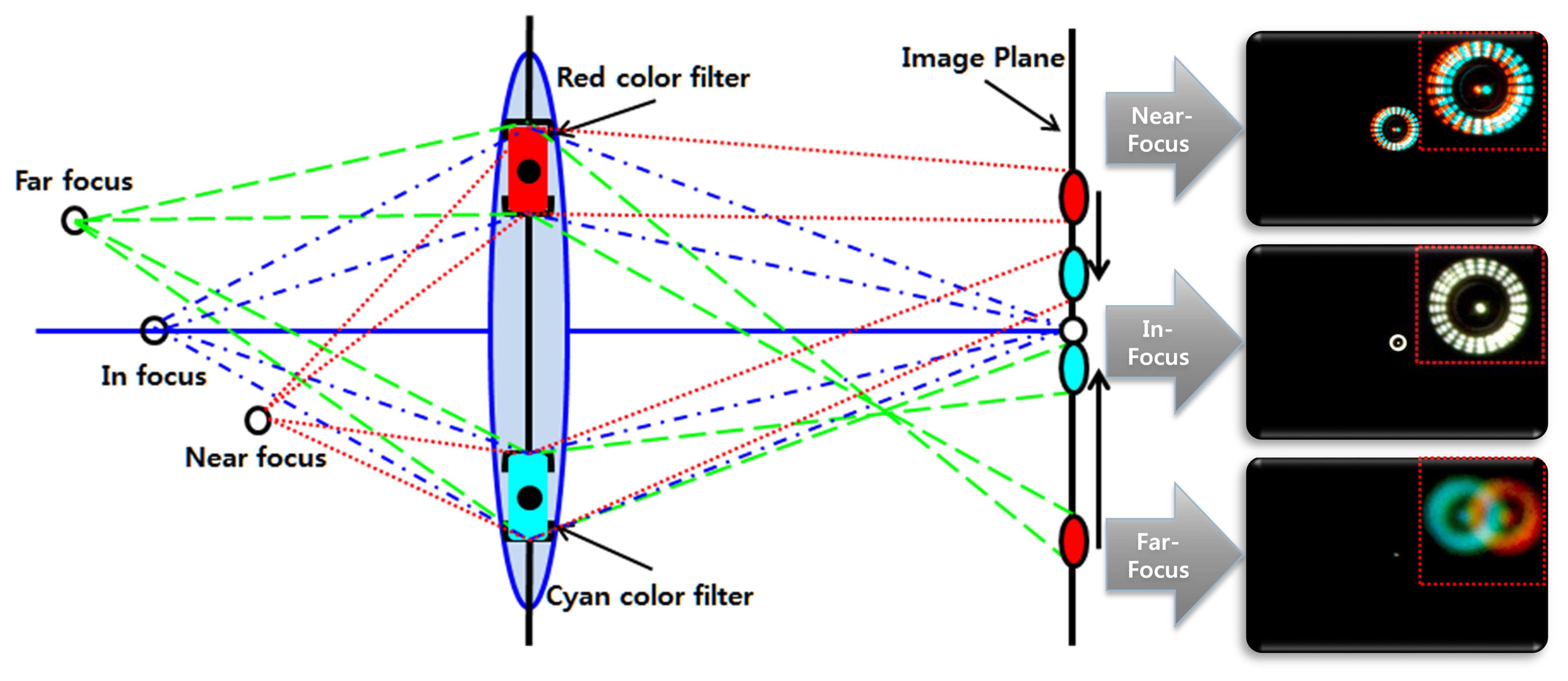
The aperture of an optical system is the opening device that adjusts the amount of light entering the image sensor. The center of the aperture in the traditional imaging system is generally aligned with the optical axis of the lens. If there are two off-axis apertures, the convergence pattern of the projected point on the image plane is divided into the two projected points if the object is not located at the plane of focus. The distance between two separated convergence patterns depends on the distance of the object from the camera. It is noted that we cannot estimate the distance between two projected regions if they are mixed together.
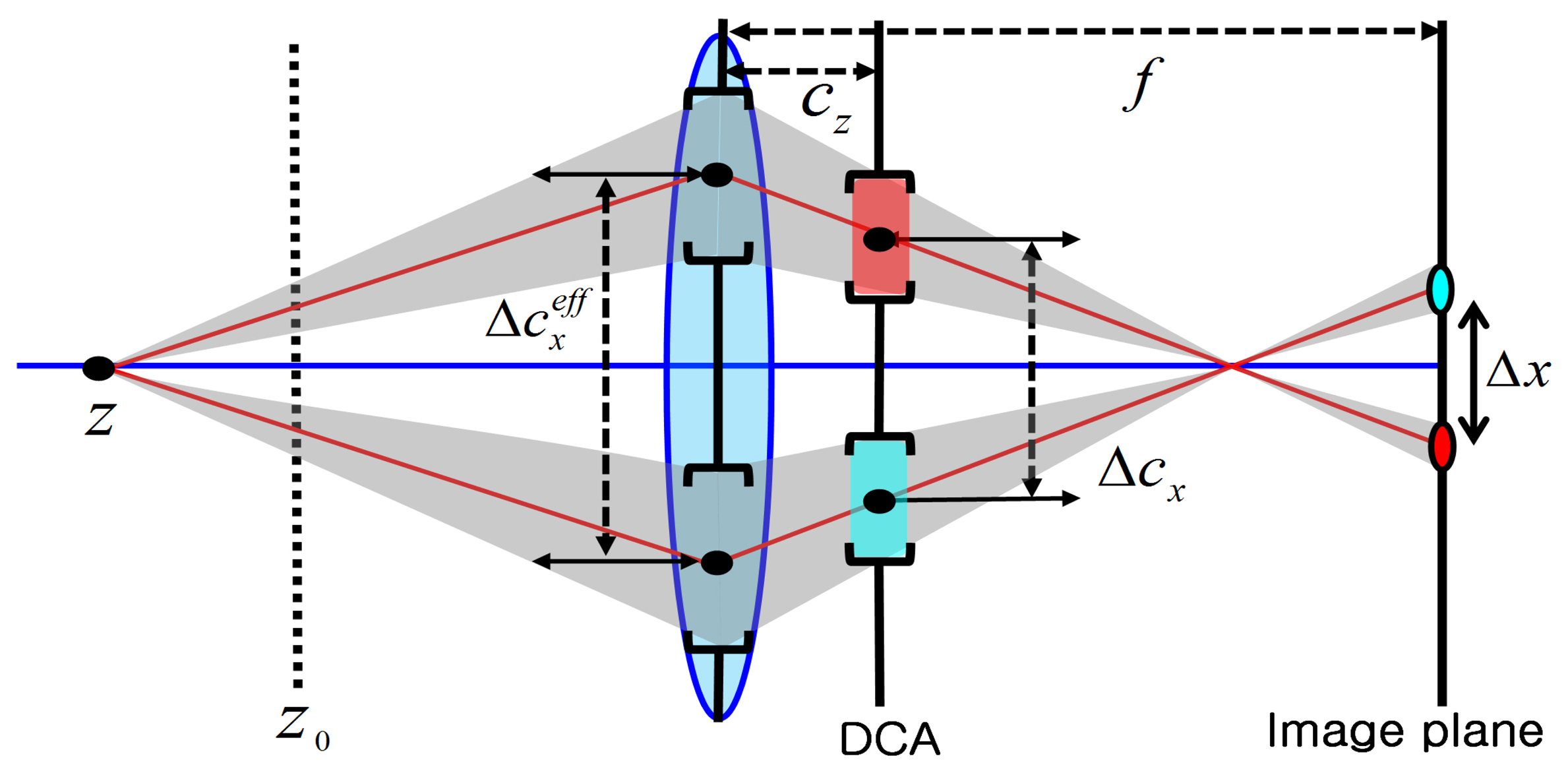
In order to separate two regions, we covered apertures using two different color filters that generate geometric disparity between two color images. For the complete color shift model using the DCA camera, we use two apertures with red (R) and cyan (C) filters, whose centers are located on the same line crossing the optical axis. The color shift model can provide the geometric disparity of misalignment, which can be estimated from the amount of color deviation between the pair of two projected points, as shown in Figure 2. Thus, the distance of the object can be estimated using the color shifting value (CSV) that corresponds to the length of the amount of misalignment between color channels from the color-misaligned image.
3. Object Moving Direction and Velocity Estimation with Tracking
The object region should be continuously tracked to estimate the 3D motion of the object while the position and scale of the object change. We use the incremental learning-based method for robust object tracking [15].
The statistical object tracking problem is usually defined as the Bayesian inference with a hidden Markov model. Given the state of an object at time t, denoted as ot, cumulated observations up to time t, denoted as Y1:t, the Bayesian filter updates a posteriori probability p(ot|y1:t) with the following rule,
Let the 2D state of the object xt at time t in the image coordinates denote xt = {xt, yt, wt, ht}, where xt and yt indicate the center position of the object, wt and ht represent the width and the height of the object, respectively. In order to convert the image coordinate system into the 3D camera coordinate system, we need to know the distance Z of the object and camera intrinsic parameters, including the focal lengths fx, fy and the principal point sx, sy.
Because two disparities between red and green and red and blue are the same with respect to the horizontal direction, the distance measure combines two energy functions as:
A more accurate estimation of Δx can be performed by a Gaussian pyramid-based iterative coarse-to-fine approach for accommodating large color shifting values between color channels [17]. In [13], Lee et al. estimated the dense depth map in the entire image. However, the proposed method estimates only one CSV by minimizing the error function in the object region. If the object region is large enough to contain meaningful features, it is almost always reliable.
In [14], the relation between Δx and the object distance Z has been derived as:
If the parameters in Equation (7) are expressed in millimeters, then Δx is also determined in millimeters. In order to express Δx in pixels, Δx has to be multiplied by the distance αx between two pixels, which is given as:
Equation (9) is similar to the relationship between the disparity and the depth in the stereo vision defined as , where B represents the baseline, except theoffset given as . Solving (9) for Z yields:
Given Z, the 2D states of the object xt and yt are transformed into 3D camera coordinate as:
The 2D states of the object wt and ht are transformed into 3D camera coordinates as:
3D object moving direction D and velocity V are then calculated as:
In ȯt, the state of the object to be used for object tracking is ot. After determining , the final 3D state of the object ȯt is then computed. Continuously estimated Z may have a minor oscillation due to the estimation error of the CSV. For robust estimation of Z, we use Kalman filtering to predict and compensate temporally changing CSV.
4. DCA Camera Calibration
For accurate depth estimation, the entire set of camera parameters, except Δx, should be calibrated. Calibration of the DCA camera consists of two steps: (i) estimation of the camera parameters, including the focal lengths, principal point and lens distortion coefficients; and (ii) estimation of the DCA parameters, including Z0 and cz.
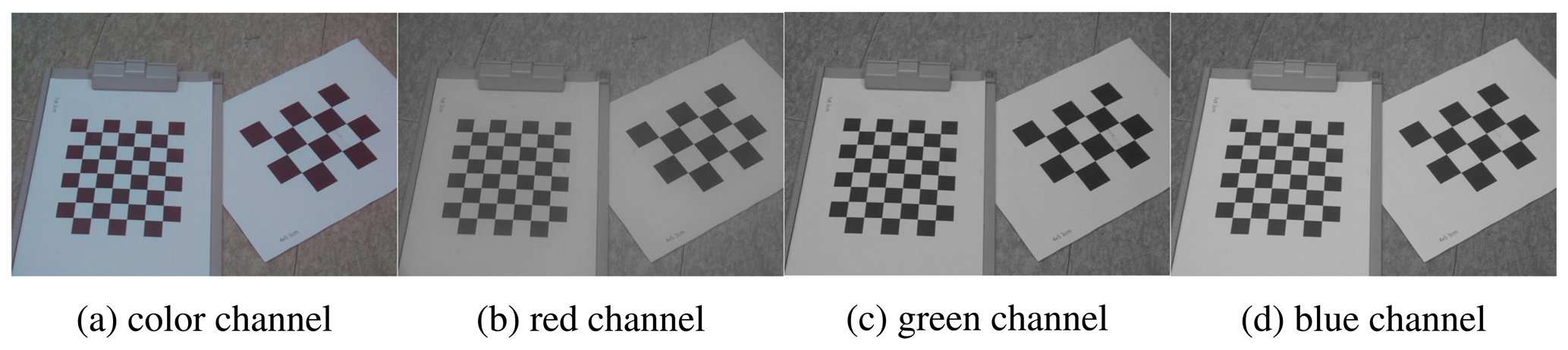
Although each color channel has the same lens distortion coefficients, because the DCA camera uses a single lens, sx and sy have to be estimated in each color channel due to two off-axis apertures, as shown Figure 4. For the calibration of the camera parameters, we took the images using a checkerboard at different camera locations and used a calibration tool at each color channel.
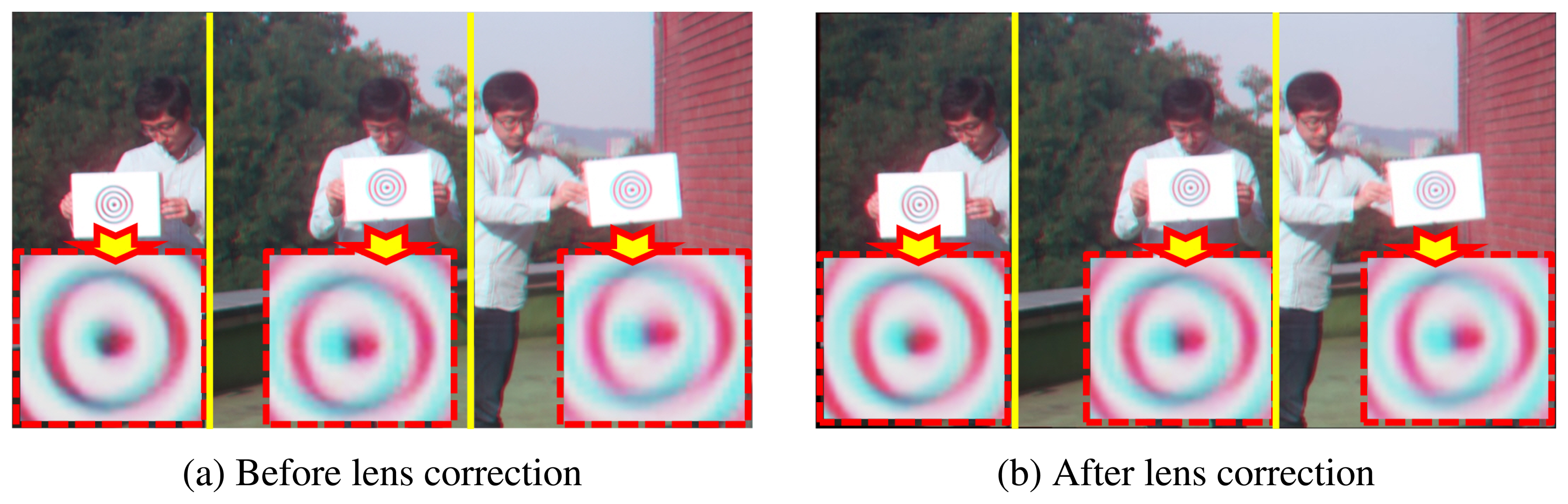
Although the object is located at the same distance, each object has different CSVs before lens correction, as shown in Figure 5a. However, after lens correction, the objects located at the same distance also have the same CSVs, as shown in Figure 5b.
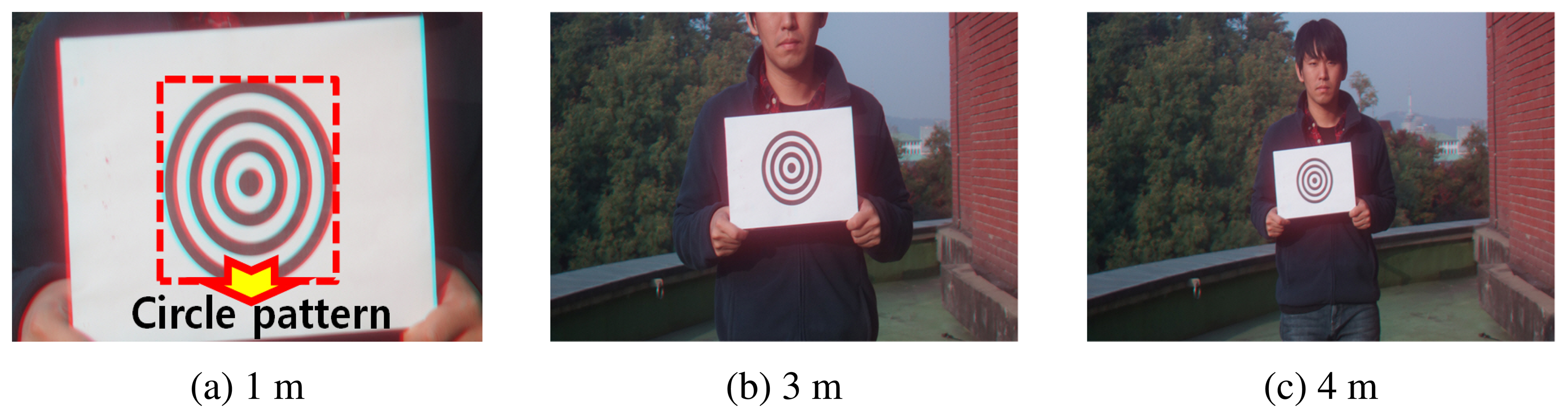
For solving Z as in Equation (10) from Δx, the unknown parameters Z0 and cz should be determined. We use a concentric circle pattern for calibrating the DCA camera and then take the image of the pattern at various distances, as shown in Figure 6. Because we know the real diameter of the circle, the distance of the concentric circle pattern can be calculated as:
For solving this equation, we need to develop more than two linear equations. Therefore, we estimate Δx from the circle pattern of more than two images and then calculate Z using Equation (15). Using these values, Equation (16) can be developed as a matrix form as:
In [14], Lee et al. estimated cz by assuming that two objects are placed at Z0 and Z1, which should be given before the estimation process. It also needs manual identification of whether the object is placed at the in-focus position to determine Z0. However, the proposed calibration method estimates the unknown parameters Z0 and cz using the least squares optimization method with the distance data acquired at different locations using the known size of the circle pattern. Because the proposed method just takes the image using the circle pattern and does not need to measure the distance of the object, it can better estimate the calibration parameters than [14].
5. Experimental Results
To demonstrate the feasibility of the DCA-based RGB-D camera for the distance estimation of the tracked object, we used a Sony NEX6 digital single lens reflected (DSLR) camera with a 18 − 55 mm lens. The resolution of the video sequence is 1920 × 1080. The DCA lens is configured by the red and the cyan color filters, and the distance between the two apertures Δcx is set to 6 mm.
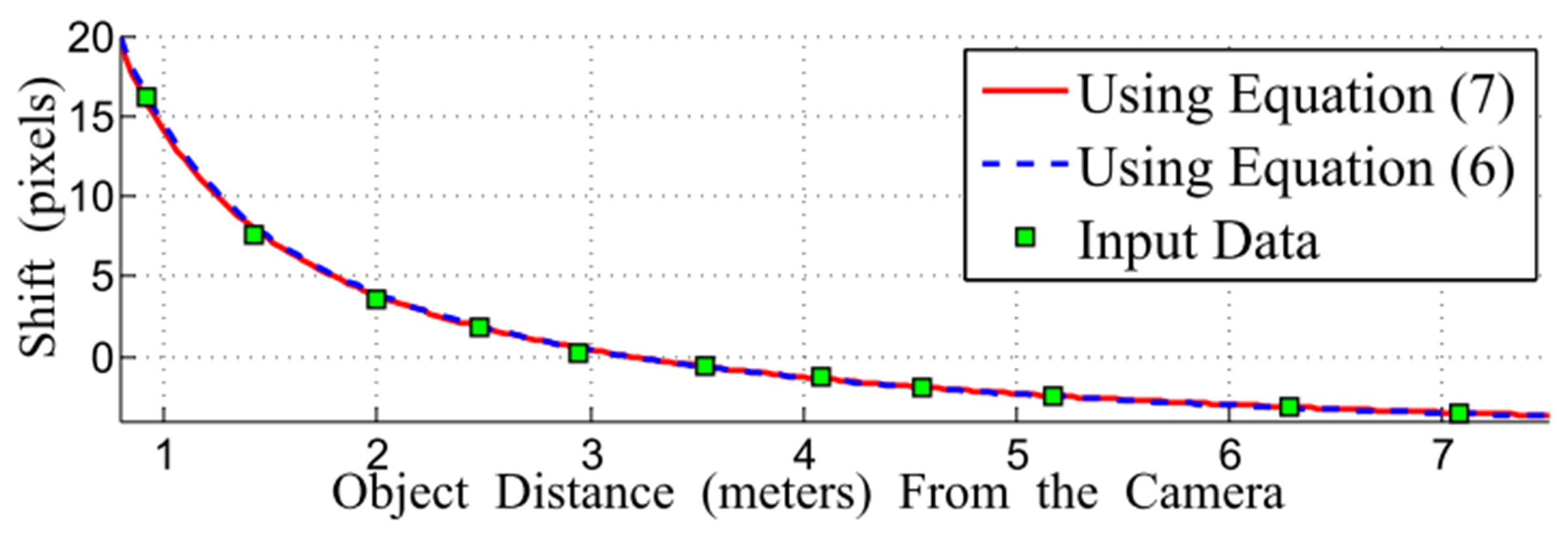
Figure 7 shows comparison of the input data for the DCA calibration. As shown in the figure, the curve of the function using Equation (9) closely passes through the input data. In addition, Equation (7) is almost the same as its approximated version in (9).
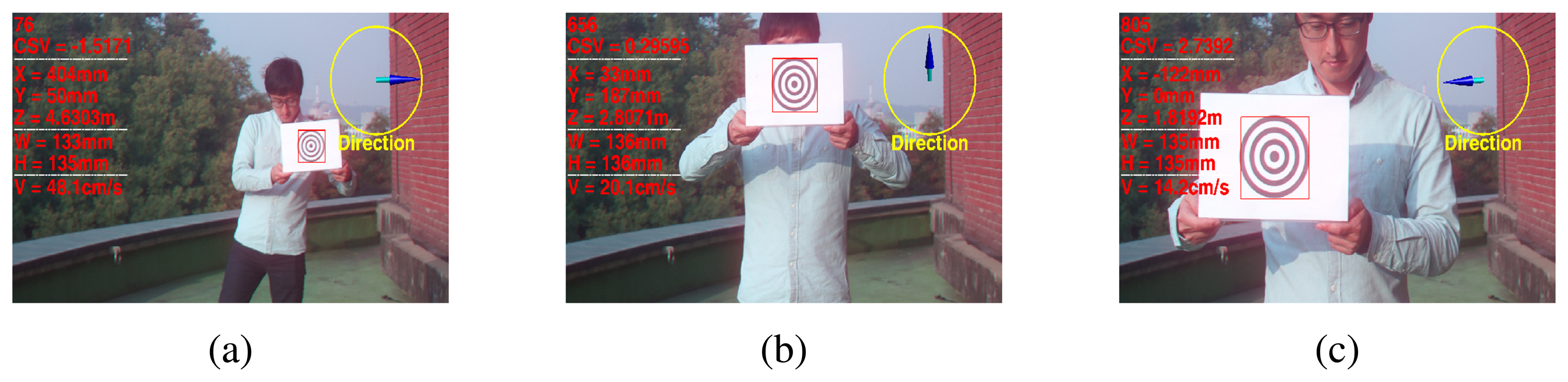
Figure 8 shows the results of the proposed 3D state estimation of the tracked object. The images were taken of this object at distances that ranged from 5 m to 1 m, and cross pattern was moved at 1-m intervals.
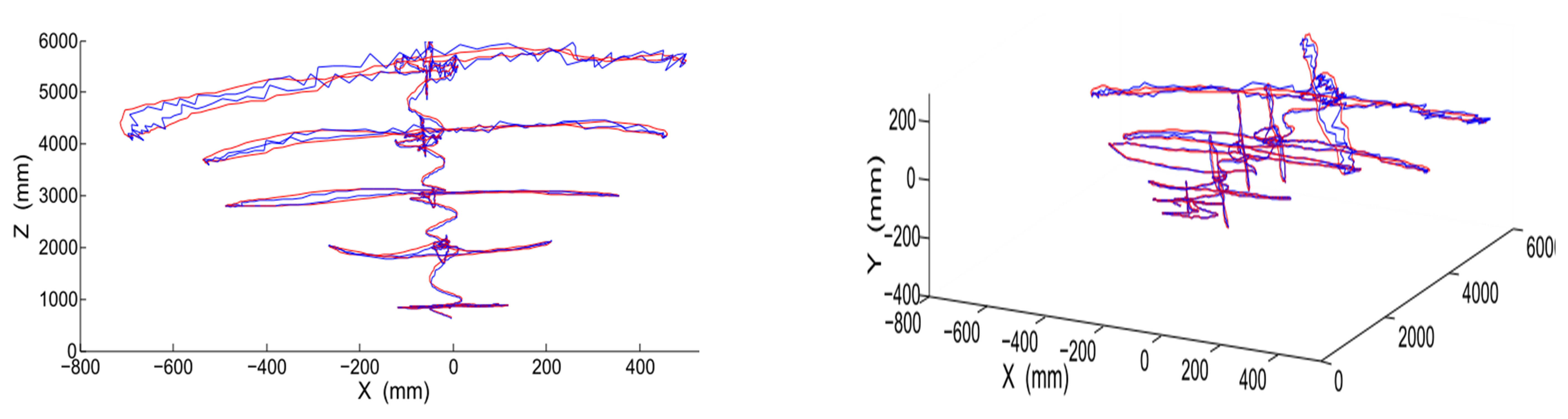
Figure 9 shows the 3D trajectory of the moving object in the camera coordinate system. The trajectory without Kalman filtering has minor oscillations due to the estimation error. However, the trajectory with Kalman filtering smoothly changes without oscillation.
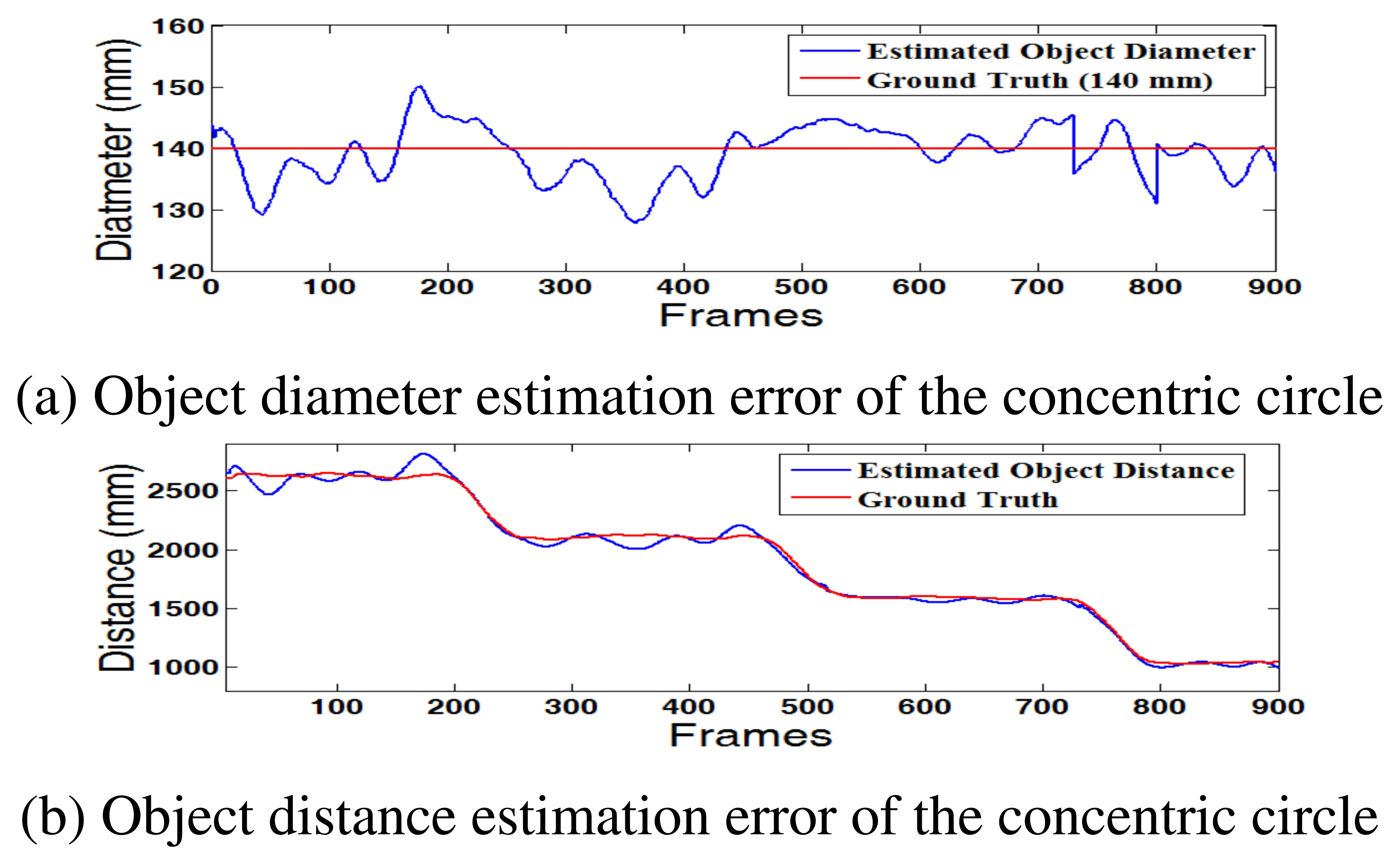
Figure 10 shows the estimation error of the distances and diameters of the concentric circle. This result can provide a key indicator for accuracy of the depth estimation. If the estimated diameter is similar to the real value, 140 mm, the estimated 3D distance is also accurate. As shown in Figure 10a, the proposed method robustly estimates the diameter of the circle with an error less than ±10 mm.
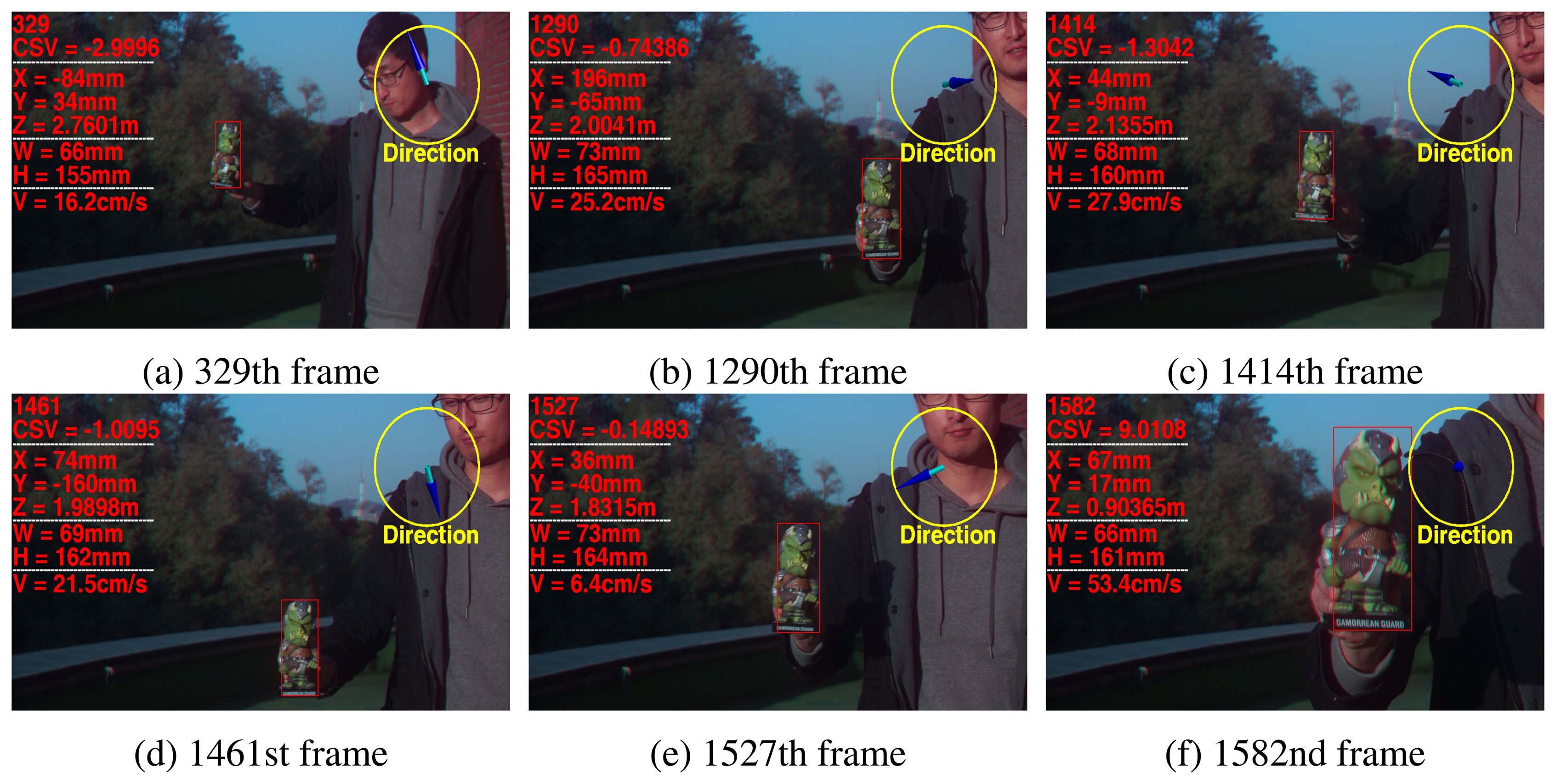
Figure 11 shows the results of the estimated 3D states of the tracked object in another scene. The object having complex patterns was also successfully tracked with the proposed 3D states of the object.
As a result, the proposed method can estimate the 3D states of an object with a single object motion. However, it cannot accurately estimate the 3D states of multiple moving objects with possible occlusions or fade-in/-out, because the object tracking method may fail to track the object.
6. Conclusions
In this paper, we proposed a novel 3D object direction and velocity estimation method for object tracking using the DCA-based computational RGB-D camera. We estimated the amount of the color shifting value as the disparity by minimizing the error function. After the proposed DCA camera calibration, the 2D states of the object were converted into the 3D camera coordinates using an approximated mathematical model of the relationship between color shifting values and the actual distance of the object. Finally, the 3D object moving direction and velocity are calculated by the temporal changes of the object.
Based on the experimental results, the DCA camera-based object tracking system can successfully estimate the three-dimensional direction and velocity of a randomly-moving object. More accurate depth estimation with the extended range will be possible using an improved sub-pixel interpolation-based registration method in future research.
Supplementary Materials
Supplementary materials can be accessed at: https://www.mdpi.com/1424-8220/15/1/995/s1.
Acknowledgments
The authors express sincere appreciation to Prof. Monson H. Hayes for his idea and advice in the initial stage of this work. This work was supported by Basic Science Research Program through the National Research Foundation (NRF) of Korea funded by the Ministry of Education, Science and Technology (2014R1A1A2055198), ICT R&D program of MSIP/IITP(14-824-09-002, Development of global multi-target tracking and event prediction techniques based on real-time large-scale video analysis) and the Technology Innovation Program (Development of Smart Video/Audio Surveillance SoCand Core Component for Onsite Decision Security System) under Grant 10047788.
Author Contributions
Seungwon Lee initiated the research and designed the experiments; Kyungwon Jeong and Jinho Park performed experiments; Joonki Paik wrote the paper
Conflicts of Interest
The authors declare no conflict of interest.
References
- Gade, R.; Moeslund, T. Thermal tracking of sports players. Sensors 2014, 14, 13679–13691. [Google Scholar]
- Li, X.; Guo, R.; Chen, C. Robust pedestrian tracking and recognition from FLIR video a unified approach via sparse coding. Sensors 2014, 14, 11245–11259. [Google Scholar]
- Le, A.; Jung, S.; Won, C. Directional joint bilateral filter for depth images. Sensors 2014, 14, 11362–11378. [Google Scholar]
- Fernandez-Sanchez, E.; Diaz, J.; Ros, E. Background subtraction based on color and depth using active sensors. Sensors 2013, 13, 8895–8915. [Google Scholar]
- Blanco, C.; Mantecon, T.; Camplani, M.; Jaureguizar, F.; Salgado, L.; Carcia, N. Foreground segmentation in depth imagery using depth and spatial dynamic models for video surveillance applications. Sensors 2014, 14, 1961–1987. [Google Scholar]
- Zhu, Y.; Fujimura, K. A bayesian framework for human body pose tracking from depth image sequences. Sensors 2010, 10, 5280–5293. [Google Scholar]
- Dhond, U.; Aggarwal, J. Structure from stereo-a review. IEEE Trans. Syst. Man Cybern. 1989, 19, 1498–1510. [Google Scholar]
- Schastein, D.; Szeliski, R. A taxonomy and evaluation of dense two-frame stereo correspondence algorithm. Int. J. Comput. Vision 2012, 47, 7–42. [Google Scholar]
- Zhou, C.; Nayar, S. Computational cameras: Convergence of optics and processing. IEEE Trans. Image Process. 2011, 20, 3322–3340. [Google Scholar]
- Maik, V.; Cho, D.; Shin, J.; Har, D.; Paik, J. Color shift model-based segmentation and fusion for digital autofocusing. J. Imaging Sci. Technol. 2007, 51, 368–379. [Google Scholar]
- Kim, S.; Lee, E.; Hayes, M.; Paik, J. Multifocusing and depth estimation using a color shift model-based computational camera. IEEE Trans. Image Process. 2012, 21, 4152–4166. [Google Scholar]
- Lee, S.; Lee, J.; Paik, J. Simultaneous Object Tracking and Depth Estimation Using Color Shifting Property of a Multiple Color-Filter Aperture Camera. Proceedings of the IEEE Conference Acoustics, Speech, and Signal Processing, Praha, Czech Republic, 22–27 May 2011; pp. 1401–1404.
- Lee, S.; Kim, N.; Jung, K.; Hayes, M.; Paik, J. Single Image-Based depth Estimation Using Dual off-Axis Color Filtered Aperture Camera. Proceedings of the IEEE Conference Acoustics, Speech, and Signal Processing, Vancouver, BC, Canada, 26–31 May 2013; pp. 2247–2251.
- Lee, S.; Hayes, M.; Paik, J. Distance estimation using a single computational camera with dual off-axis color filtered apertures. Opt. Express 2013, 21, 23116–23129. [Google Scholar]
- Ross, D.; Lim, J.; Lin, R.; Yang, M. Incremental learning for robust visual tracking. Int. J. Comput. Vision 2008, 77, 125–141. [Google Scholar]
- Lucas, B.; Kanade, T. An Iterative Image Registration Technique with an Application to Stereo Vision. Proceedings of the 7th International Joint Conference on Artificial Intelligence, Vancouver, BC, Canada, 24–28 August 1981; pp. 674–679.
- Periaswamy, S.; Farid, H. Elastic registration in the presence of intensity variations. IEEE Trans. Med. Imaging 2003, 22, 865–874. [Google Scholar]


© 2015 by the authors; licensee MDPI, Basel, Switzerland. This article is an open access article distributed under the terms and conditions of the Creative Commons Attribution license ( http://creativecommons.org/licenses/by/4.0/).
Share and Cite
Lee, S.; Jeong, K.; Park, J.; Paik, J. Three-Dimensional Object Motion and Velocity Estimation Using a Single Computational RGB-D Camera. Sensors 2015, 15, 995-1007. https://doi.org/10.3390/s150100995
Lee S, Jeong K, Park J, Paik J. Three-Dimensional Object Motion and Velocity Estimation Using a Single Computational RGB-D Camera. Sensors. 2015; 15(1):995-1007. https://doi.org/10.3390/s150100995
Chicago/Turabian StyleLee, Seungwon, Kyungwon Jeong, Jinho Park, and Joonki Paik. 2015. "Three-Dimensional Object Motion and Velocity Estimation Using a Single Computational RGB-D Camera" Sensors 15, no. 1: 995-1007. https://doi.org/10.3390/s150100995