A Unitary ESPRIT Scheme of Joint Angle Estimation for MOTS MIMO Radar

Abstract
: The transmit array of multi-overlapped-transmit-subarray configured bistatic multiple-input multiple-output (MOTS MIMO) radar is partitioned into a number of overlapped subarrays, which is different from the traditional bistatic MIMO radar. In this paper, a new unitary ESPRIT scheme for joint estimation of the direction of departure (DOD) and the direction of arrival (DOA) for MOTS MIMO radar is proposed. In our method, each overlapped-transmit-subarray (OTS) with the identical effective aperture is regarded as a transmit element and the characteristics that the phase delays between the two OTSs is utilized. First, the measurements corresponding to all the OTSs are partitioned into two groups which have a rotational invariance relationship with each other. Then, the properties of centro-Hermitian matrices and real-valued rotational invariance factors are exploited to double the measurement samples and reduce computational complexity. Finally, the close-formed solution of automatically paired DOAs and DODs of targets is derived in a new manner. The proposed scheme provides increased estimation accuracy with the combination of inherent advantages of MOTS MIMO radar with unitary ESPRIT. Simulation results are presented to demonstrate the effectiveness and advantage of the proposed scheme.1. Introduction
Multiple-input multiple-output (MIMO) radar is a radar system transmitting multiple linearly independent waveforms which enables joint data processing received by multiple receive antennas. As an emerging field of radar research, MIMO radar has attracted intensive research [1–5]. In terms of the antenna configuration, MIMO radars can be divided into two types: widely separated antennas [3] or colocated antennas [4,5] which includes bistatic and monostatic MIMO radar with transmit and receive antennas closely spaced. Over conventional phased-array counterparts, MIMO radars offer unique advantages, such as extra degrees of freedom offered by waveform diversity [6], higher resolution and better parameter identifiability [7], and a larger virtual or effective aperture than the real aperture [8].
However, the advantages offered by the MIMO radar come at the price of sacrificing transmit directional gain at the transmit array. Since MIMO radar transmits each orthogonal waveform omni-directionally, it is faced with the problem of SNR gain loss which is unfavorable for angle estimation. One of the solutions to alleviate the SNR gain loss is subarray MIMO radar. Subarray MIMO can be grouped into overlapped and non-overlapped cases according to the subarray configuration. In this paper, we focus on the type of the overlapped subarray configuration [9], which is different from the non-overlapped situation that antennas of transmit array are simply partitioned into subarrays without transmit coherent processing [10]. The overlapped transmit subarray (OTS) for MIMO radar has a transmit coherent gain which results in improvement in SNR per virtual element, while non-overlapped configuration does not have such a gain. In essence, this type of subarray MIMO radar can be regarded as a tradeoff between phased-array and MIMO radar, and more details could be found in [9]. The transmit array of the subarray MIMO radar is divided into several OTSs, and the transmit waveforms are coherent within each OTS while orthogonal to the waveform transmitted by other OTSs. In addition, transmit beam-pattern optimization with respect to the beamforming weights of the subarrays can be employed to focus transmitted energy and improve the SNR gain per virtual element [11]. However, transmit beampattern optimization is often a high computation work.
Angle estimation of multiple targets is one of the most important applications of radar system in practice. Some classic estimation algorithms, such as Capon, multiple signal classification (MUSIC) and Estimation of signal parameters via rotational invariance techniques (ESPRIT), have been applied to MIMO radar [5,10–17]. In bistatic MIMO radar, direction of arrival (DOA) and direction of departure (DOD) of multiple targets are obtained and paired automatically. Methods in [5,12] require an exhaustive peak search or root finding over the unknown parameters and hence bear high computational cost if the search is performed over a fine grid. The ESPRIT based methods proposed in [10,13–16] both take full advantage of the rotational invariance property of the uniform linear array and they are free of peak searches and achieves two-dimensional angle estimations. Moreover, [13] provides an effective ESPRIT scheme for multiple subarrays in monostatic MIMO, but its focus is on beam-pattern optimization, which is a high computation work. Methods in [10] and [16] are effective for just three transmit antennas configuration and only two non-overlapped subarrays with three or more transmit antennas, respectively. Unitary ESPRIT is applied in [17], which provides increased estimation accuracy with a reduced computational burden.
Among the methods above, the directional gain of transmit array of bistatic MIMO radar is not exploited. Without taking transmit directional gain into consideration, they all suffer from low SNR per virtual antenna as a result of dividing the total transmit energy over different waveforms without transmit coherent gain. In this paper, we propose a method of joint DOA and DOD of multiple targets present in the same range-bin for bistatic MIMO radar configured with multi-overlapped-transmit-subarray (MOTS), which we call MOTS MIMO radar for short. First, all the OTSs are partitioned into two groups which has a rotational invariance relationship. Then, a synthetic observation data matrix whose data samples can be doubled is built, in terms of the property of centro-Hermitian matrix. And the rotational invariance relationship obtained can be transformed into real-valued. Finally, the DOAs and DODs of targets can be solved in closed form in a new manner and paired automatically.
The rest of this paper is organized as follows. In Section 2, we briefly introduce the signal model of MOTS MIMO radar. In Section 3, a new unitary ESPRIT method is applied to MOTS MIMO radar. MOTS configuration systems are considered and the closed-form solution of angles is derived. In Section 4, the computational complexity of the proposed method is evaluated. The simulations results that show the advantages of the proposed scheme are presented in Section 5, which is followed by the conclusions in Section 6.
Notation: Scalars, column vectors and matrices are expressed by regular, bold lowercase and bold uppercase, respectively. (·)* (·)T (·)H and (·)−1 denote conjugate, transpose, conjugate transpose and matrix inverse, respectively. IN represents a N × N identity matrix, ΠMN stands for the MN × MN exchange matrix with ones on its antidiagonal and zeros elsewhere, diag(·) denotes a diagonalization operator and E[·] denotes the expectation operator. ⨂ and ⨀ represent Kronecker product and Hadamard product, respectively.
2. Signal Models of MOTS MIMO Radar
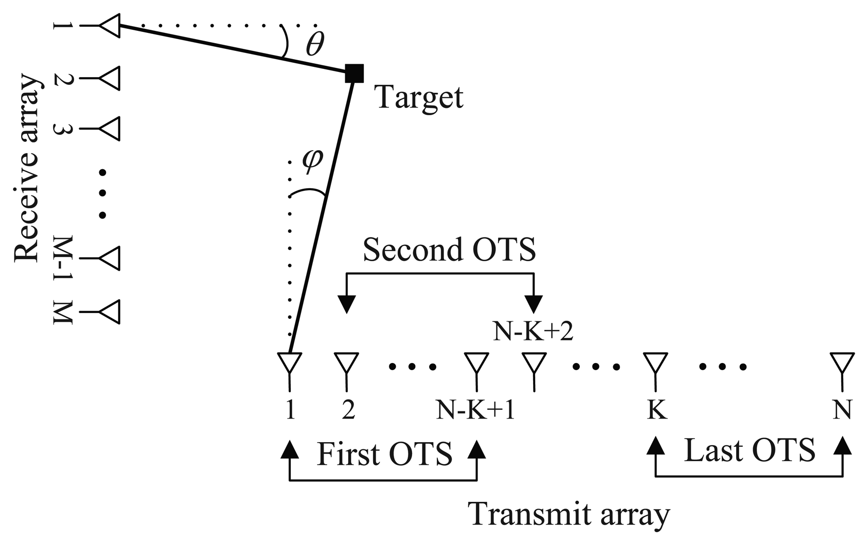
Consider a bistatic MIMO radar system, shown in Figure 1, with N transmit antennas and M receive antennas, both of which are half-wave-length spaced uniform linear arrays (ULAs). The transmit array is partitioned into a total of K OTSs (2 ≤ K ≤ N), and the kth OTS contains Nk = N − K + 1 array elements, i.e., each OTS has the identical effective aperture. Let with qr = e−jπ sin(φ) and with qt = e−jπ sin(θ) denote as transmit and receive steering vectors, respectively. ak(φ) denotes the steering vector associated with the kth OTS which is an Nk × 1 subvector formed from the a(φ). the waveform transmitted by the kth OTS is denoted by ϕk (tl)T ∈ ℂ1×Q where l = 1, 2, …, L, ϕk (tl)Tϕk (tl) = 1, ϕki (tl)Tϕkj (tl) = 0(ki, kj = 1, 2, …, K; ki ≠ kj), tl = lTr denotes the slow time where Tr is the pulse repetition interval, l is the slow time index and L is the number of pulses. We assume that there are P targets at the same range bin with different Doppler frequencies. fp denotes Doppler frequency with p = 1, 2, …, P. donates the unit-norm complex vector of beamforming weights associated with the kth OTS. The signal reflected by the pth target located in the far-field can be then modeled as
Then, the K × 1 vector of the transmit coherent gain and waveform diversity vector can be introduced as follows,
At the receive array, the array observations can be written as
By match-filtering X to each of the waveforms , we can form the output of the match filter within the duration of L pulses, which is corresponding to the kth OTS
3. A Unitary ESPRIT Method for MOTS MIMO
In this section, the MOTS configuration, i.e., the number of OTSs is K, is taken into account. From Equation (6) we can easily obtain data Yk, where k = 1, 2, …, K. After stacking the individual components Yk in one column, we obtain the following observation data matrix
As seen from Figure 1, every Nk elements of transmit array is used to form the identical OTS. All the OTSs are partitioned into two groups, which are composed of the first and last (K − 1) OTSs, respectively. From Equations (6) and (7), a rotational invariance relationship can be developed as
Then, we build a synthetic observation data matrix, whose data samples can be doubled. The synthetic data matrix defined as
It can be shown that Z is centro-Hermitian [18]. According to the theorem in [19], a centro-Hermitian matrix can be mapped to a real matrix. The real-valued matrix from the complex-valued Z via a unitary transformation can be obtained as:
Then the P dominant left singular vectors Es ∈ RMK×P of the real-valued matrix Ω can be computed through a real-valued singular value decomposition (SVD) of Ω. Alternatively, Es can be also computed through a real-valued eigenvalue decomposition (ED) of . There exists a nonsingular matrix T ∈ RP×P such that
For the pth target, the shift invariance relation in (13) can then be written as
Note that the two selection matrices satisfy ΠM(K − 1) J1ΠMK = J2. As a result,
Let K1 and K2 , respectively, be the real and imagin)ary parts of with and . Then, with Equation (15) substituted into Equation (14), we can obtain:
According to the definition of the tangent function, Equation (16) can be rewritten as:
For all the P targets, the complex-valued rotational invariance relation in Equation (8) can be transformed into the real-valued manifold as follows:
Note that V is the estimate of T−1. In terms of Equation (12), it can be obtained
It is shown that the DODs and DOAs of targets can be paired automatically.
4. Computational Complexity Analysis
In order to analyze the complexity for the computation of the proposed method, we have to know the complexity of the SVD algorithm, which is the main computational burden. Since the computational complexity of the SVD is varying with different methods [20]. Among them, an efficient orthogonal iteration approach for SVD algorithm has a complexity in order of O(MNr) for an M × N matrix truncated to rank r. Based on this point, the main computational cost of the ESPRIT method in [15] is O (M2N2P). Different from the MN × MN complex-valued covariance matrix in the ESPRIT method, the covariance matrix of the unitary ESPRIT in [17] with the same size MN × MN is real-valued.Since the complexity of complex-valued computation is higher than that of the real-valued, the computational complexity of the unitary ESPRIT in [17] is O(μM2N2P), where μ < 1. The computational complexity of our method is O(μM2K2P), which is approximately equal to unitary ESPRIT in [17] and lower than ESPRIT in [15].
5. Simulation Results
Consider a traditional bistatic MIMO radar which consists of a ULA of M = 8 receive antennas and a ULA of N = 6 omni-directional transmit antennas, which are spaced half a wavelength apart from each other. The N transmit antennas transmitting N orthogonal waveforms, and the nth waveform transmitted is the nth row of S ∈ ℂQ×Q, where and HQ is the Q × Q Hadamard matrix. Based on the configuration of the traditional bistatic MIMO radar, the MOTS MIMO radar improves its transmitter which has K OTSs transmitting K orthogonal waveforms and the kth transmitted waveform ϕk (tl) is the kth row of S. Q = 256 is the number of samples per pulse period, and Tr = 64 μs is the pulse repetition interval. Assume that there exists P = 3 noncoherent sources, which are located at angles (φ1, θ1) = (20°,-20°) , (φ2, θ2) = (−18°, 10°) and (φ3, θ3) = ( 5°, 35°) , and the reflection coefficients of the targets are . The Doppler frequencies are . The additive noise is Gaussian zero-mean unit-variance spatially and temporally white. The average root mean square error (ARMSE) of the angle estimation is defined as:
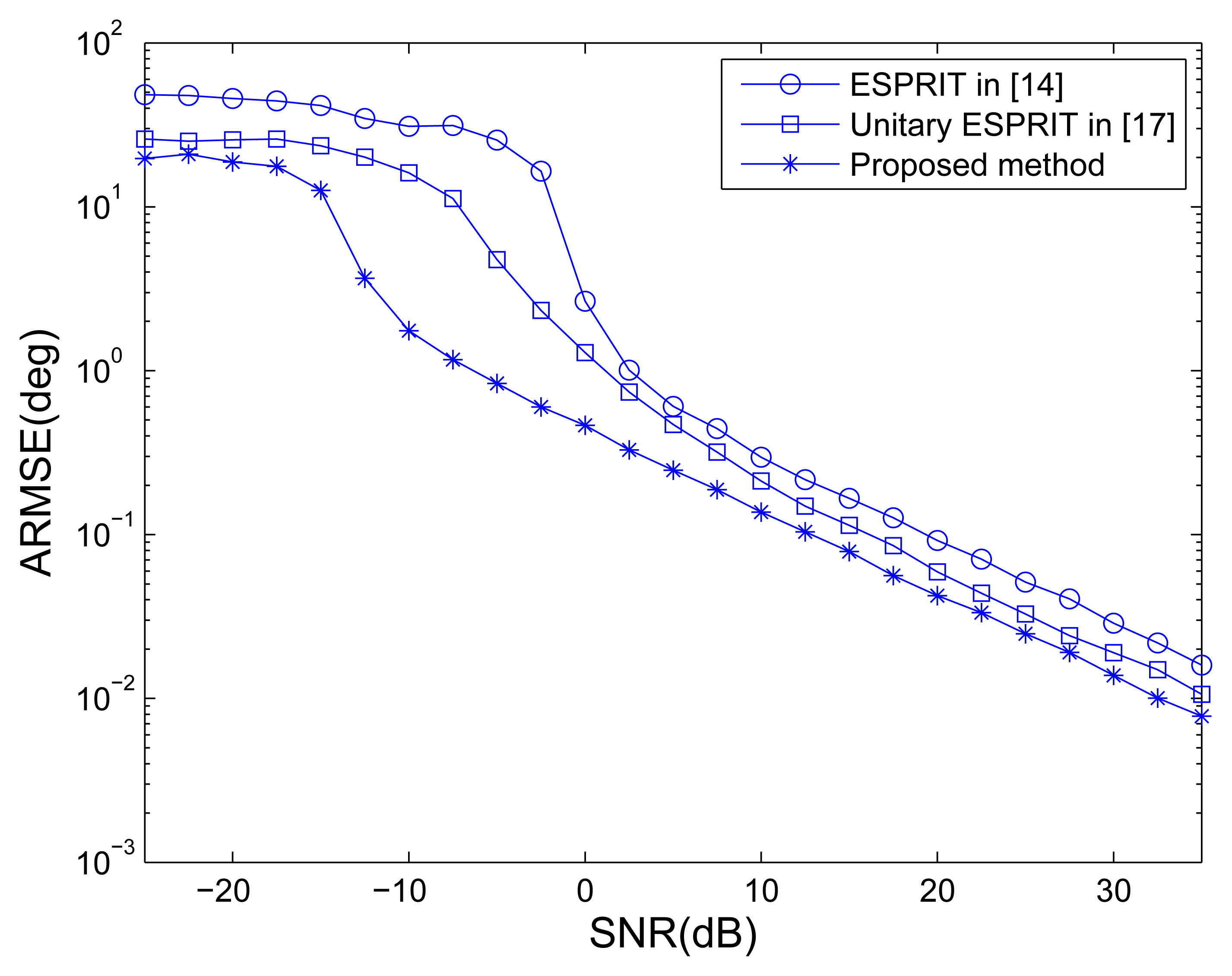
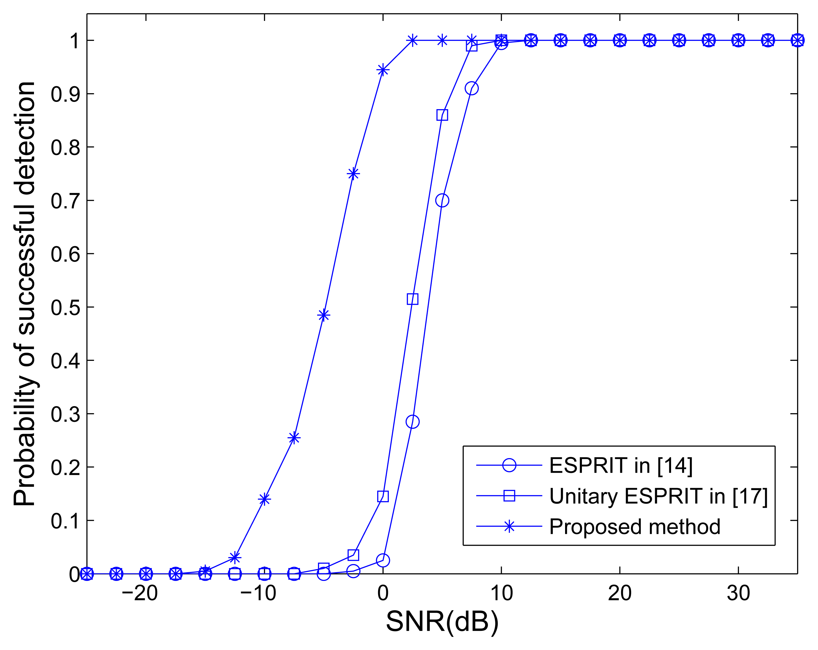
The traditional MIMO radar employing ESPRIT [15] and unitary ESPRIT [17], and MOTS MIMO with K = 3 OTSs employing our method are used to compare. Figure 2 shows the ARMSE of angle estimation of different methods versus SNR, where L = 40. It can be seen that the traditional MIMO radar employing unitary ESPRIT has better performance of angle estimation than ESPRIT. It can also be observed that the traditional MIMO radar employing ESPRIT and unitary ESPRIT provide worse accuracy performance than the MOTS MIMO employing the proposed method. The MOTS MIMO radar has the smaller effective aperture as the traditional MIMO radar but higher SNR per virtual element due to transmit coherent processing. It yields the comparative advantage of the proposed scheme over traditional MIMO scheme, especially at lower SNR region. Figure 3 shows the probability of the successful detection of the different methods versus SNR. The absolute errors |φ̂p − φp| ≤ 0.5° and |θ̂p − θp| ≤ 0.5° are both required for the successful detection of DOD and DOA for all three targets. It can be seen from Figure 3 that all the methods exhibit a 100% successful detection at high SNR values. As the SNR decreases, the probability of successful detection starts dropping for each method at a certain point. The SNR level at which the transition happens is known as the SNR threshold. It also can be seen that MIMO employing ESPRIT and MIMO employing unitary ESPRIT have the highest and the second highest SNR thresholds, respectively. In contrast, the proposed method has the lowest SNR threshold, i.e., the best probability of the successful detection.
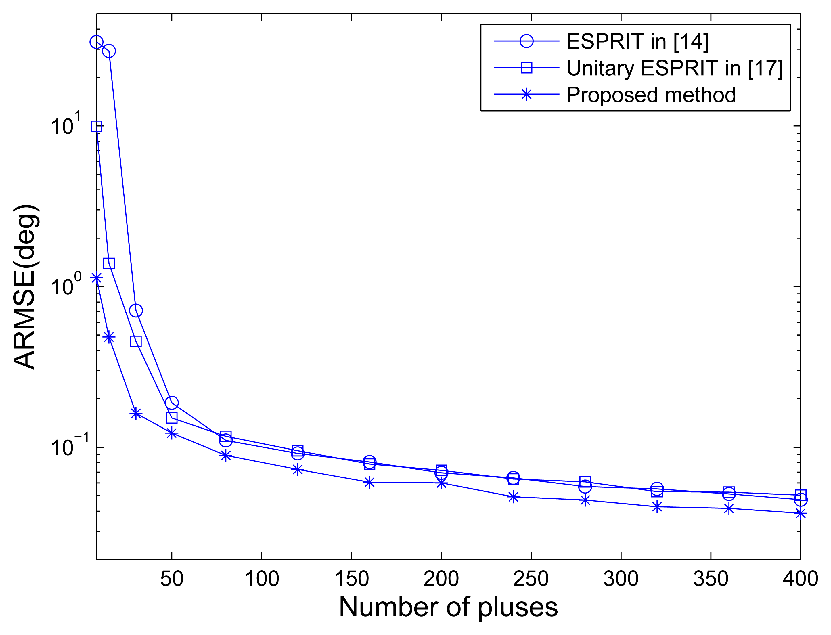
Figure 4 shows the RMSE of angle estimation of different methods versus the number of pulses under SNR = 10 dB. It is indicated that the unitary ESPRIT has better angle estimation performance than the ESPRIT in traditional MIMO configuration especially in small pulse number case. The performance improvement is lost for large pulse number, and this may be caused by the averaging of the number of pulses without SNR improvement. The MOTS MIMO employing the proposed method has the best performance of angle estimationin all pulse number cases, mainly due to the SNR improvement per virtual element via transmit coherent processing.
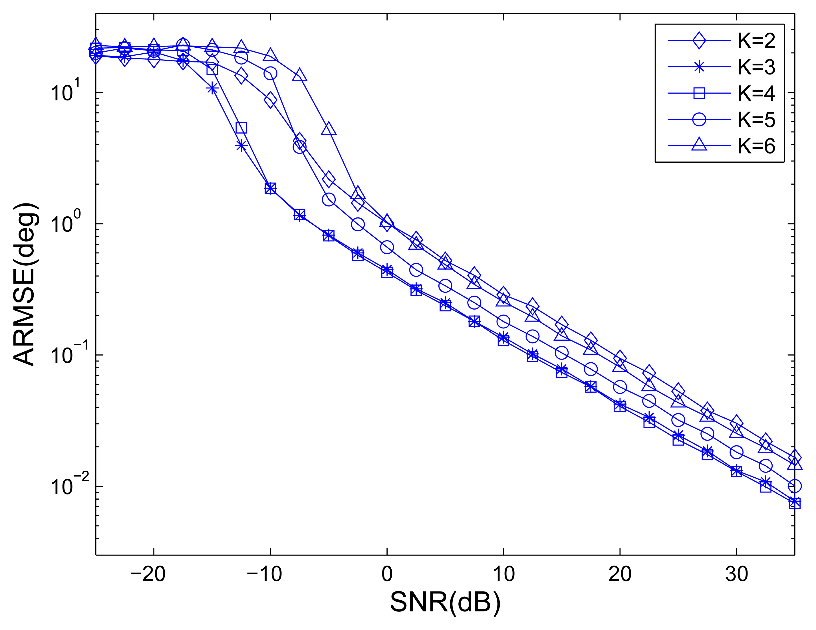
For different numbers of OTSs, Figure 5 shows the ARMSE of angle estimation of MOTS MIMO employing the proposed method versus SNR , where L = 40. Note that if K = 1 is chosen, the whole transmit array is considered as one subarray and only one waveform is emitted, there is no estimation of DODs. When K = 6 is chosen, the MOTS MIMO becomes the MIMO radar without subarray partitioning, which has largest effective aperture but no transmit coherent gain. It can be easily seen that the angle estimation performances are the best when the number of OTSs is equal to 3 or 4. It is the fact that effective aperture becomes larger with an increase in the number of OTSs K while SNR gain per virtual antenna becomes lower. It is the combination of effective aperture and SNR gain per virtual antenna that has an impact on the estimation performance. It also can be observed that the MOTS MIMO with K = 3 slightly outperforms the MOTS MIMO with K = 4 at low SNR region while the opposite occurs at high SNR region. This means that having high SNR gain per virtual antenna is more important at low SNR region, while having large effective aperture is more important at high SNR region. Thus, K is chosen as the tradeoff between effective aperture and SNR gain per virtual antenna.
6. Conclusions
In this paper, a unitary ESPRIT scheme is presented to DOD and DOA estimation for MOTS MIMO radar. The proposed method exploits the combination of inherent advantages of MOTS MIMO radar with unitary ESPRIT. The MOTS MIMO improves the SNR gain through the carefully chosen number of OTSs, which is a tradeoff between effective aperture and SNR gain per virtual antenna. The proposed method, which is based on unitary ESPRIT, doubles the data samples and reduces the computational burden. Our scheme for MOTS MIMO provides increased estimation accuracy of angle estimation with DODs and DOAs of targets solved in closed form and automatically paired in a simple manner. Several experimental results have demonstrated the performance of the proposed scheme.
Acknowledgments
This work was Specialized Research Fund for the Doctoral Program of Higher Education (Nos. 20130203130001, 20130203120009), the National Natural Science Foundation of China (No. 61227004), the 111 Project (No. B07048), the Fundamental Research Funds for the Central Universities (No. K5051399020).
Author Contributions
All authors contributed extensively to the study presented in this manuscript. Chao Wen designed the main idea, methods and experiments, carried out the experiments, interpreted the results and wrote the paper. Guangming Shi supervised the main idea, edited the manuscript and provided many valuable suggestions to this study.
Conflict of Interest
The authors declare no conflicts of interest.
References
- Fishler, E.; Haimovich, A.; Blum, R.; Chizhik, D.; Cimini, L.; Valenzuela, R. MIMO radar: An idea whose time has come. Proceedings of the IEEE Radar Conference, Philadelphia, PA, USA, 26–29, April 2004; pp. 71–78.
- Li, J.; Stoica, P. MIMO radarâᾸŞdiversity means superiority. Proceedings of the 14th Adaptive Sensor Array Processing Workshop (ASAP'06), Lexington, MA, USA, 11–13, September 2006; pp. 1–6.
- Haimovich, A.M.; Blum, R.S.; Cimini, L.J. MIMO radar with widely separated antennas. IEEE Signal Process. Mag. 2008, 25, 116–129. [Google Scholar]
- Bekkerman, I.; Tabrikian, J. Target detection and localization using MIMO radars and sonars. IEEE Trans. Signal Process. 2006, 54, 3873–3883. [Google Scholar]
- Yan, H.; Li, J.; Liao, G. Multitarget identification and localization using bistatic MIMO radar systems. EURASIP J. Adv. Signal Process. 2008, 2008, 48. [Google Scholar]
- Bliss, D.W.; Forsythe, K.W. Multiple-input multiple-output (MIMO) radar and imaging: Degrees of freedom and resolution. Proceedings of the 37th Asilomar Conference on Signals, Systems and Computers, Pacific Grove, CA, USA, 7–10, November 2004; pp. 54–59.
- Li, J.; Stoica, P.; Xu, L.; Roberts, W. On parameter identifiability of MIMO radar. IEEE Signal Process. Lett. 2007, 14, 968–971. [Google Scholar]
- Robey, F.C.; Coutts, S.; Weikle, D.; McHarg, J.C.; Cuomo, K. MIMO radar theory and experimental results. Proceedings of the 37th Asilomar Conference on Signals, Systems and Computers, Pacific Grove, CA, USA, 7–10, November 2004; pp. 300–304.
- assanien, A.; Vorobyov, S.A. Phased-MIMO radar: A tradeoff between phased-array and MIMO radars. IEEE Trans. Signal Process. 2010, 58, 3137–3151. [Google Scholar]
- Chen, J.; Gu, H.; Su, W. A new method for joint DOD and DOA estimation in bistatic MIMO radar. Signal Process. 2010, 90, 714–718. [Google Scholar]
- Ren, S.; Ma, X.; Yan, S.; Hao, C. 2-D unitary ESPRIT-like direction-of-arrival (DOA) estimation for coherent signals with a uniform rectangular array. Sensors 2013, 13, 4272–4288. [Google Scholar]
- Zhang, X.; Xu, L.; Xu, L.; Xu, D. Direction of departure(DOD) and direction of arrival (DOA) estimation in MIMO radar with reduced-dimension MUSIC. IEEE Commun. Lett. 2010, 14, 1161–1163. [Google Scholar]
- Hassanien, A.; Vorobyov, S.A. Transmit energy focusing for DOA estimation in MIMO radar with colocated antennas. Signal Process. 2011, 59, 2669–2682. [Google Scholar]
- Duofang, C.; Baixiao, C.; Guodong, Q. Angle estimation using ESPRIT in MIMO radar. Electron. Lett. 2008, 44, 770–771. [Google Scholar]
- Jinli, C.; Hong, G.; Weimin, S. Angle estimation using ESPRIT without pairing in MIMO radar. Electron. Lett. 2008, 44, 1422–1423. [Google Scholar]
- Jin, M.; Liao, G.; Li, J. Joint DOD and DOA estimation for bistatic MIMO radar. Signal Process. 2009, 89, 244–251. [Google Scholar]
- Zheng, G.; Chen, B.; Yang, M. Unitary ESPRIT algorithm for bistatic MIMO radar. Electron. Lett. 2012, 48, 179–181. [Google Scholar]
- Haardt, M.; Nossek, J.A. Unitary ESPRIT: How to obtain increased estimation accuracy with a reduced computational burden. IEEE Trans. Signal Process. 1995, 10, 1232–1242. [Google Scholar]
- Lee, A. Centrohermitian and skew-centrohermitian matrices. Linear Algebra Appl. 1980, 29, 205–210. [Google Scholar]
- Golub, G.H.; Van Loan, C.F. Matrix Computations; Johns Hopkins University Press: Baltimore, MD, USA, 1996. [Google Scholar]


© 2014 by the authors; licensee MDPI, Basel, Switzerland. This article is an open access article distributed under the terms and conditions of the Creative Commons Attribution license ( http://creativecommons.org/licenses/by/3.0/).
Share and Cite
Wen, C.; Shi, G. A Unitary ESPRIT Scheme of Joint Angle Estimation for MOTS MIMO Radar. Sensors 2014, 14, 14411-14422. https://doi.org/10.3390/s140814411
Wen C, Shi G. A Unitary ESPRIT Scheme of Joint Angle Estimation for MOTS MIMO Radar. Sensors. 2014; 14(8):14411-14422. https://doi.org/10.3390/s140814411
Chicago/Turabian StyleWen, Chao, and Guangming Shi. 2014. "A Unitary ESPRIT Scheme of Joint Angle Estimation for MOTS MIMO Radar" Sensors 14, no. 8: 14411-14422. https://doi.org/10.3390/s140814411